installation and setup guide - duplex plusz ...duplexplusz.hu/file/xl2tiiv2.pdfcancel code, and...
TRANSCRIPT
XXLL--22TTSecurity System
Installation and Setup Guide
N9833V2 2/00

XL-2T Installation & Setup Guide
ii

iii
THANK YOU for your purchase of theXL-2T Security System.
The purpose of this manual is to give you a brief overview of the XL-2T control panel, and provide instruc-tions for installing a basic system. FBII is always available to serve YOU. Our SALES and TECHNICALSUPPORT staff are available to assist you in any way possible.
FOR TECHNICAL SERVICE,CALL TOLL-FREE
1-800 645-7492
Before you call Technical Service, PLEASE be sure you:
• Check the wiring diagram and verify your connections.• Check all fuses.• Ensure that the transformer and backup battery voltages are supplying the proper voltage levels.• Verify your programming information.• Read this manual thoroughly.• Consult the Troubleshooting Section of this Manual.• Note the proper model number of this product, and the version level (if known) along with any docu-
mentation that came with the product.• Have your company name and telephone number ready.
This information will allow us to service you more quickly and effectively. Please, remember to BE PATIENTwhile waiting on the telephone; your call will be answered as soon as possible.
FOR YOUR CONVENIENCE, a System Planning Worksheet and a Programming Worksheet are included atthe back of this manual. These can be removed to help you record account information.

iv
Table of Contents• • • • • • • • • • • • • • • • • • • • • • • • • • • • • • • • • • • • • • • • • • • • • • • • •
CONVENTIONS USED IN THIS MANUAL ........................................................................................VI
XL-2T TO XL-2 COMPARISON ..........................................................................................................VII
S E C T I O N 1 - INTRODUCTION.......................................................................................1–1Features ........................................................................................................................................ 1–1Compatible Keypads...................................................................................................................... 1–2
S E C T I O N 2 - PC BOARD AND KEYPAD MOUNTING.............................................2–1Mounting the XL-2T PC Board...................................................................................................... 2–1Mounting the XK-4600RM Keypad ................................................................................................ 2–2Mounting the XK-4600SM Keypad................................................................................................. 2–3Mounting the XK-406 and 6615 Keypads ...................................................................................... 2–4Surface Mounting the XK-508 and XK-5LC Keypads ..................................................................... 2–5Surface Mounting the XK-7LC Keypad.......................................................................................... 2–5Recess Mounting the XK-7LC Keypad............................................................................................ 2–6
S E C T I O N 3 - SYSTEM WIRING AND HOOKUP ........................................................3–1System Wiring Diagram ................................................................................................................ 3–1Terminal Connections.................................................................................................................... 3–2Auxiliary Device Current Draw Worksheet.................................................................................... 3–7Wiring Information for Keypads and Other Devices....................................................................... 3–7
S E C T I O N 4 - KEYPAD FEATURES..............................................................................4–1Keypad Layout .............................................................................................................................. 4–1System Mode Summary ................................................................................................................. 4–4Keypad Sounder ............................................................................................................................ 4–5Keypad Addressing........................................................................................................................ 4–5
S E C T I O N 5 - SYSTEM OPERATION............................................................................5–1Power-Up/System Reset................................................................................................................. 5–1Arming the System ........................................................................................................................ 5–1Stay Arming .................................................................................................................................. 5–1Instant Arming.............................................................................................................................. 5–2Stay/Instant Arming...................................................................................................................... 5–2System Mode Summary ................................................................................................................. 5–2Disarming...................................................................................................................................... 5–2Reset ............................................................................................................................................. 5–2Bypass by Zone/Group ................................................................................................................... 5–2Quick Bypass by Zone/Group......................................................................................................... 5–3Auto Unbypass .............................................................................................................................. 5–4Manual Unbypass.......................................................................................................................... 5–4User Code Programming................................................................................................................ 5–4User Deletion................................................................................................................................. 5–5Keypad Emergency Conditions ...................................................................................................... 5–5Quick Command Modes ................................................................................................................. 5–5Installer Modes.............................................................................................................................. 5–8

v
Table of Contents• • • • • • • • • • • • • • • • • • • • • • • • • • • • • • • • • • • • • • • • • • • • • • • • •
S E C T I O N 6 - SYSTEM PROGRAMMING....................................................................6–1General.......................................................................................................................................... 6–1Programming Questions ................................................................................................................ 6–1Pager ............................................................................................................................................. 6–3Dual Reporting .............................................................................................................................. 6–3Single Reporting............................................................................................................................ 6–4Backup Dialing.............................................................................................................................. 6–4Zone Descriptor Programming ..................................................................................................... 6–29
S E C T I O N 7 - DATA ENTRY VIA KEYPADS...............................................................7–1General.......................................................................................................................................... 7–1How to Enter Programming Mode via Either LED or LCD Keypads .............................................. 7–1What You See on the LED Keypads ............................................................................................... 7–1What You See on the LCD Keypad................................................................................................. 7–2How to Enter Data......................................................................................................................... 7–2
S E C T I O N 8 - SYSTEM DEFAULTS ..............................................................................8–1
S E C T I O N 9 - SUMMARY OF KEYPAD FUNCTIONS................................................9–1User Functions .............................................................................................................................. 9–1Installer Modes.............................................................................................................................. 9–1
APPENDIX A - CENTRAL STATION REPORTING FORMATS..................................................A–1Standard (3x1 or 4x1) ....................................................................................................................A–1Extended (3x1 Ext. or 4x1 Ext.) .....................................................................................................A–2Partial Extended (3x1 Part. Ext. or 4x1 Part. Ext.)........................................................................A–23x2 or 4x2......................................................................................................................................A–2FBII Superfast (4x3x1) ..................................................................................................................A–3ADEMCO 4x1 Express...................................................................................................................A–3ADEMCO 4x2 Express...................................................................................................................A–3ADEMCO Point ID........................................................................................................................A–4
APPENDIX B - TROUBLESHOOTING.............................................................................................B–1
APPENDIX C - SYSTEM PLANNING WORKSHEET....................................................................C–1
APPENDIX D - SYSTEM PROGRAMMING WORKSHEET .........................................................D–1
APPENDIX E - WARNINGS AND LIMITATIONS...........................................................................E–1
APPENDIX F - REGULATORY AGENCY STATEMENTS ...........................................................F–1
APPENDIX G - WARRANTY INFORMATION ............................................................................... G–1
vi
Conventions Used in This Manual• • • • • • • • • • • • • • • • • • • • • • • • • • • • • • • • • • • • • • • • • • • • • • • • •
Before you begin using this manual, it is important that you understand the meaning of thefollowing symbols (icons) and text note.
UL These notes include specific information that must be followed if you are installing this system fora UL Listed application.
These notes include information that you should be aware of before continuing with the installa-tion, and which, if not observed, could result in operational difficulties.
This symbol indicates a critical note that could seriously affect the operation of the system, orcould cause damage to the system. Please read each warning carefully. This symbol also alertsthe user to the possibility of physical harm if instructions are not followed as written.
NOTE: These text notes are provided throughout the manual to provide information and shortcut tips forthe installer.

vii
XL-2T to XL-2 Comparison• • • • • • • • • • • • • • • • • • • • • • • • • • • • • • • • • • • • • • • • • • • • • • • • •
The XL-2T is an enhanced version of the XL-2 control panel. Some new features have been added and othershave been modified. The following is a quick HELP comparison.
XL-2T NEW & MODIFIED FEATURES XL-2 SIMILAR FEATURES7 Zones: all fully programmable, including Keyswitch.......7 Zones: 6 fully programmable + 1 prog. only
• (Program Questions 17-23)Zone Loop Types (EOL, N/O, or N/C) ..................................EOL Loop Type Only
• (Program Questions 17-23)Audible or Silent by Zone ..................................................Audible Only
• (Program Questions 17-23)15 User Codes & Door Strike User Capability ....................6 User Codes: No Door Strike User CapabilityBell Supervision - New NFPA 72 Requirement .....................NONE
• (Program Question 22)Unattended Download (Installer Mode 8) ...........................Standard Download OnlyOn-line Download (Installer Mode 9) ..................................Standard Download OnlyAdditional Formats: FBI Superfast, Point ID .....................Pulse Formats Only
• (Program Questions 7 & 8)Dual CS Reporting ............................................................Single CS Reporting
• (Program Questions 7 & 8)16-Digit Phone Numbers (CS1 & CS2) ................................12-Digit Phone Numbers (CS1 & CS2)Built-in Siren Driver or Conventional Bell Output ............Conventional Bell Output Only
• (Program Question 12)Cross Zoning to Prevent False Alarms ...............................NONE
• (Program Questions 17-23)2 Entry Timers .................................................................1 Entry Timer
• (Program Question 11)Swinger Shutdown - Bell and Dialer Lockout ........................Bell Lockout
• (Program Question 04)Call Waiting /PBX Dialing - 1-digit entry ............................Multiple digits required
• (Program Questions 01 & 02)78-Event History (Alarms, Troubles, Low Battery) .................Alarm Memory (cleared by user code)
• Not cleared by user code (Installer Mode 4)2 Programmable Output Triggers ......................................NONE
Terminal P1• (Program Question 14)
CS Test Timer - 1 Hr, 1 Day, 7 Day, 27 Day, ..........................CS Test Timer: 1 Day Only by Event60 Day, or 90 Day by Time, Event, or Both• (Program Question 10)
Recent Close Code.............................................................NONE• (Program Question 35)
End User Chime ON/OFF Toggle (Quick Com. [#] 6).............NONEExit Error Warning (always enabled)...................................NONEQuick Exit .........................................................................NONE
• (Program Question 9)Arm While Faulted ............................................................NONE
• (Program Question 12)Restore Follows Bell or Loop .............................................Restore Follows Bell Only
• (Program Question 07)System Stabilization on Power-Up - to Eliminate ...............NONE
Motion Detector False AlarmsFast Loop Response (10mSec) Option by Zone ...................NONE
• (Program Questions 17-23)
XL-2T NEW & MODIFIED FEATURES XL-2 SIMILAR FEATURESAC (50/60 Hz) Based System Real-Time Clock ....................Software-Based System Timing

viii
• (Program Question 07)Stay Mode 40 Sec. Dialer Delay w/ Bell & Keypad ..............Stay Mode Entry Delay w/ Keypad Sounder
Sounder Warning for All Zones warning for Exit/Entry Zones Only• (Program Question 12)
Auto Arming in Different Modes .......................................NONE• (Program Question 08)
LED Display and Sounder on Entry Zone ..........................Sounder Only(always enabled)
Programmable Dialer Attempts: 1 - 15 ...............................Non-programmable 8 Dialer Attempts• (Program Question 09)
LED Extinguish on Keypads ..............................................NONE• (Program Question 12)
Keypad Tamper/Lockout ..................................................NONE• (Program Question 12)
Bell Supervision (enabled when Fire Zone is .........................NONEprogrammed)
Separate Fire Trouble & Day Trouble Codes .....................Same Code for both• (Program Question 32)
Temporal Bell....................................................................NONE• (Program Question 12)
AC/Low Battery Keypad Sounder Disable..........................NONE• (Program Question 12)
Dial Tone Detect Dialer .....................................................Dialer will not detect dial tone• (Program Question 13)
Fire Zone Type without Verification..................................NONE• (Program Questions 17-23)
Interior Follower Zone Type without Stay Arming ............NONE• (Program Questions 17-23)
Chime Trigger ...................................................................NONE• (Program Question 14)
Alarm Reset Trigger ..........................................................NONE• (Program Question 14)
Pulse Sound During Exit Time ..........................................NONE• (Program Question 06)
Exit Time Restart ..............................................................NONE• (Program Question 11)
Walk Test Mode .................................................................NONE• (Program Question 30)
Pager Format ...................................................................NONE• (Program Question 07)
Exit Delay When Armed in ................................................No Exit DelayInstant or Stay Instant Mode
Over Three Zones Bypassable............................................Program Question 09, Location 3CS Test Does Ring Back ....................................................Program Question 13, Location 1Dial Delay Option of 15 or 30 seconds ................................Program Question 13, Location 1Cancel Display on an LCD Keypad ....................................Program Question 13, Location 1Only User 4 Will Send Open and Close Report ...................Program Question 13, Location 2Keypad Sounder Beeps During Exit Time..........................Program Question , Location

1–1
S E C T I O N 1
Introduction• • • • • • • • • • • • • • • • • • • • • • • • • • • • • • • • • • • • • • • • • • • • • • • • •
FeaturesThe XL-2T is a state-of-the-art microprocessor-based control/communicator. The system fea-tures seven fully programmable zones. Programming can be performed through any of thecompatible keypads, or the system can be uploaded and downloaded remotely using theEZMATE/COMPASS PC Downloader Software. Additionally, the software can be pr o-grammed to control remote actions, such as arming, disarming, bypassing, etc. Programmingoptions are stored in an Electrically Erasable Programmable Read-Only Memory (EEPROM).The EEPROM is nonvolatile, meaning that programmed instructions will not be lost in theevent of a loss of power.Features of the XL-2T include:• 7 zones (all fully programmable, including keyswitch)• 15 user codes (Ambush, Arm only, and Door Strike capability)• Pager formatting capability• Keypad programming and remote programming via PC and modem• Upload/download and remote commands with answering machine override capability• 3 methods of uploading/downloading: PC operator-initiated, unattended
downloading, and on-line downloading• Optional built-in 2-tone siren driver or conventional bell output• Auto arming at a specific time of day with capability to arm in either Away, Stay, or
Instant mode• Dual-entry timers• 78-event history log (alarms, troubles, low battery, bypasses, Central Station (CS) test,
openings, and closings)• 3 emergency keypad conditions (panic, fire, and auxiliary)• 2 programmable trigger outputs• Real-time clock (displays time and date via LCD keypad) with reminder when clock needs
to be set• CS Test timer by event, time, or both (1 hour, 1, 7, 27, 60, 90 days)• Customer control of Chime mode• Quick Arming, Quick Bypass, and Quick Force Arming• CS reporting by zone
• False alarm prevention features: Cross Zone, Exit Error, Recent Close, Swinger ShutdownCancel Code, and System Stabilization during power-up
• Arming by keyswitch in Away or Stay mode• Keypad tamper/lockout with optional CS reporting• Restore transmission options: After Loop or After Bell• Fire zone reset through keypad• Glassbreak reset through keypad• Bell Test, Low Battery Test, AC loss, and Communications Failure• Input power: 12VAC, 20VA; 12VDC, 4-7AH• Output power: 12VDC, 500mA• Bell output power: 12VDC, 1A• Exit delay when armed in Instant or Stay Instant mode

XL-2T Installation & Setup Guide
1–2
Compatible Keypads
The XL-2T security system is compatible with the following keypads only:
LED STYLE KEYPADS LCD STYLE KEYPADS
XK-406* XK-5LC**XK-508** XK-7LC**
XK-4600RM*XK-4600SM*
6615*
* Non-Addressable Keypad** Addressable Keypad
KEYPAD NOTES:
• The system supports Light Emitting Diode (LED) style keypads or Liquid Crystal Dis-play (LCD) style keypads.
• DO NOT USE addressable and non-addressable keypads in a single installation.• If only six zones must be displayed, up to four LED style keypads may be installed in the
system.
• If all seven zones must be displayed, either the XK-508, XK-5LC, or XK-7LC keypadmust be used.
Failure to install and program this unit in accordance with the UL requirement is a violation of thelisting mark. For more information on UL Listings, contact Underwriters Laboratories, ProgressDepartment, 333 Pfingsten Road, Northbrook IL 60062.
The XL-2T is a Residential (Household) control panel and has been listed by UnderwritersLaboratories for the following applications:• UL 1023 Household Burglary
• UL 985 Household Fire Warning
2–1
S E C T I O N 2
PC Board and Keypad Mounting• • • • • • • • • • • • • • • • • • • • • • • • • • • • • • • • • • • • • • • • • • • • • • • • •
Mounting the XL-2T PC Board
To make it easier to install the control panel, the door of the metal cabinet may be removed.Remove the door as follows:
1. With the cabinet laying on a flat surface, swing open the door to its full-open position.
2. Slide the door out of its retaining slots in the cabinet and store in a safe place.
Before mounting printed circuit board, make sure you remove all appropriate metal knockoutsfrom the metal cabinet. do not attempt to remove the knockouts after circuit board has beeninstalled.
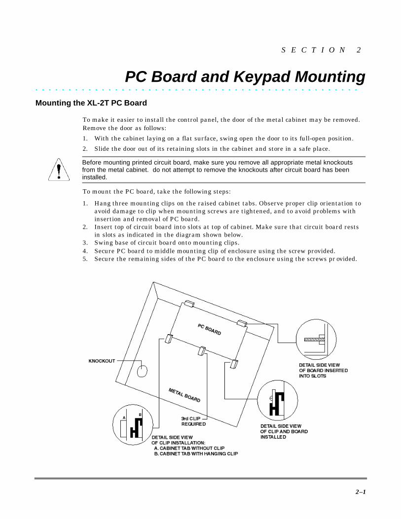
To mount the PC board, take the following steps:
1. Hang three mounting clips on the raised cabinet tabs. Observe proper clip orientation toavoid damage to clip when mounting screws are tightened, and to avoid problems withinsertion and removal of PC board.
2. Insert top of circuit board into slots at top of cabinet. Make sure that circuit board restsin slots as indicated in the diagram shown below.
3. Swing base of circuit board onto mounting clips.4. Secure PC board to middle mounting clip of enclosure using the screw provided.5. Secure the remaining sides of the PC board to the enclosure using the screws pr ovided.

XL-2T Installation & Setup Guide
2–2
Mounting the XK-4600RM Keypad
FLUSH MOUNTING USING DOUBLE-GANG BOX
1. Create an opening and mount a standard dou-ble-gang box.
2. Secure keypad to double-gang box as shown ingraphic at left.
NOTE: Mount the double-gang box flush with wallin order for keypad screws to fit.
For UL installations, mount the XK-4600RM toan earth-grounded outlet box.
FLUSH MOUNTING WITH MOUNTING RING (Using the XL-4600TR)
1. Create the desired opening where keypad is tobe mounted, using the inside of the mountingring as a template.
NOTE: We recommend that this opening be madebetween studs.
2. Secure mounting plate to wall through thefour outer holes using suitable mountinghardware (not pr ovided).
3. Connect keypad wiring to control panel andsecure keypad to mounting ring using fourpainted screws provided.
SURFACE MOUNTING (Using optional XK-4600RMBX)
1. Depending on type of installation, run keypadwiring out of the rear top, bottom, or sides ofthe backbox.
2. Secure mounting plate to wall through thefour outer holes using suitable mountinghardware (not pr ovided).
3. Connect keypad wiring to control panel andsecure keypad to mounting ring using fourpainted screws provided.
MOUNTING KEYPAD IN CONTROL PANEL ENCLOSURE
1. Remove keypad knockout from front of metalbox enclosure, as shown on left.
2. Insert XK-4600RM into opening from front ofenclosure.
3. Secure keypad to enclosure using the fourpainted metal screws and nuts provided.
UL
Section 2 - PC Board and Keypad Mounting
2–3
Mounting the XK-4600SM KeypadThe XK-4600SM Keypad may be surface-mounted in the following ways:A. Directly to a control panel having a keypad cutout on the front of its enclosure.B. Directly to a single-gang or double-gang electrical junction box.C. Directly to a wall or other surface.
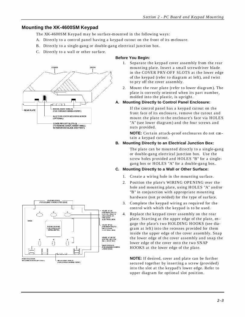
Before You Begin:1. Separate the keypad cover assembly from the rear
mounting plate. Insert a small screwdriver bladein the COVER PRY-OFF SLOTS at the lower edgeof the keypad (refer to diagram at left), and twistto pry off the cover assembly.
2. Mount the rear plate (refer to lower diagram). Theplate is correctly oriented when its part number,molded into the plastic, is upright.
A. Mounting Directly to Control Panel Enclosure:
If the control panel has a keypad cutout on thefront face of its enclosure, remove the cutout andmount the plate to the enclosure's face via HOLES"A" (see lower diagram) and the four screws andnuts provided.NOTE: Certain attack-proof enclosures do not con-tain a keypad cutout.
B. Mounting Directly to an Electrical Junction Box:
The plate can be mounted directly to a single-gangor double-gang electrical junction box. Use thescrew holes provided and HOLES "B" for a single-gang box or HOLES "A" for a double-gang box.
C. Mounting Directly to a Wall or Other Surface:
1. Create a wiring hole in the mounting surface.2. Position the plate's WIRING OPENING over the
hole and mounting plate, using HOLES "A" and/or"B" in conjunction with appropriate mountinghardware (not pr ovided) for the type of surface.
3. Complete the keypad wiring as required for thecontrol with which the keypad is to be used.
4. Replace the keypad cover assembly on the rearplate. Starting at the upper edge of the plate, en-gage the plate's two HOLDING HOOKS (see dia-gram at left) into the recesses provided for theminside the upper edge of the cover assembly. Snapthe lower edge of the cover assembly and snap thelower edge of the cover onto the two SNAPHOOKS at the lower edge of the plate.
NOTE: If desired, cover and plate can be furthersecured together by inserting a screw (provided)into the slot at the keypad's lower edge. Refer toupper diagram for optional slot position.

XL-2T Installation & Setup Guide
2–4
Mounting the XK-406 and 6615 KeypadsMounting is identical for the XK-406 and 6615 (LED type) keypads. The keypads can be surface-mounted or flush-mounted as described below.
SURFACE MOUNTING1. Select a mounting location and place the rear plate of
the keypad on the wall. Mark the location of the cut-out for the keypad wiring cable.
2. Create a keypad opening. Connect the keypad wiringto the control panel with 4-wire connector.
3. Place the keypad wiring through the cutout andsecure the back plate to the wall (see diagram atleft).
4. Connect the keypad wiring connector to the keypadand place the keypad on the mounting plate attached tothe wall.
5. Secure the keypad to the rear mounting plate by at-taching the 5/8 inch screw provided in the lower hole,located behind the keypad door.
RECESSED MOUNTING
1. Select a mounting location. For recessed mounting, this must be between two studs. The rear mountingplate is not used for recessed installations.
2. Create an opening in the wall exactly 4 inches high by 5 13/16 inches wide as shown in left diagram.
3. Turn over the keypad and remove the Phillips head screws, (items 1 and 2 in above diagram). Thesescrews are located in the upper left hand side of the keypad printed circuit board, immediately to the leftof the keypad connector.
4. Attach the black metal mounting strap to the rear of the keypad as follows (see right diagram above):a. Face the pointed end of the mounting strap facing the keypad front. This will be used to latch onto
the inside of the wall.b. Place the small white plastic spacer under the mounting strap. Secure the mounting strap, using the
5/8 inch Phillips head screw (supplied) and the plastic spacer, to item 1 hole above.c. Secure the other end of the strap (item 2 in above diagram) to the white plastic opening, using one of
the Phillips head screws removed in step 3.5. Connect the white plastic tab into the round opening immediately behind the keypad door. Place the
longer Phillips head screw (included) through the opening inside the keypad door and begin to tightenthe screw. Tighten the screw and leave the tab in a down position.
6. Run the keypad wiring to the control panel and attach the wiring to the keypad.7. Place the keypad into the wall opening with the side containing the black metal strap first until it grabs
the inside of the wall.8. After inserting the side of the keypad with the metal strap, insert the other side into the opening until
the entire keypad is firmly in the wall.
5 13/16"
(15 cm)
(10 cm) 4"

Section 2 - PC Board and Keypad Mounting
2–5
Surface Mounting the XK-508 and XK-5LC KeypadsMounting is identical for the XK-508 and XK-5LC LCD type keypads. The keypads are surface-mounted as described below.
1. Separate the two halves of the keypad by placing astraight-slot screwdriver into one of the two slots atthe bottom of the keypad and twisting.
2. Select the desired keypad mounting location andplace the plastic rear plate of the keypad on thewall. Mark the location of the cutout for the keypadwiring.
3. Create an opening for the keypad wiring in the loca-tion previously marked. Run the keypad wiring tothe control panel using the four-wire connector pr o-vided.
4. Place the keypad wiring through the cutout pro-vided and secure the keypad backplate to the wallthrough the holes provided (see diagram at left).
5. Connect the keypad wiring connector to the keypadand place the keypad on the mounting plate at-tached to the wall.
6. Snap the keypad front onto the the keypad back.
The XK-7LC LCD keypad contains an adjustment screw, located behind the door of the keypad,to vary the intensity of the display (refer to item 4 in the following diagram).
Surface Mounting the XK-7LC Keypad1. Select the desired mounting location (between wall
studs) for the keypad.2. Separate the two halves of the keypad by opening
the door (item 1 on diagram at left) and removingthe Phillips head screw (item 2). Carefully pullapart the front and rear sections of the keypad.Place the plastic rear section of the keypad on thewall and mark the location of the cutout for thekeypad wiring.
3. Create an opening for the keypad wiring in the loca-tion previously marked. Run the keypad wiring tothe control panel using the four-wire connector pr o-vided.
4. Place the keypad wiring through the cutout pro-vided and secure the keypad backplate to the wallthrough the three holes shown (see lower diagram)using screws provided.
5. Connect the keypad wiring connector plug to themating keypad connector receptacle. Position thefront section of keypad over the backplate attachedto the wall.
6. Using the 5/8-inch screw provided, secure the key-pad to the backplate through the upper hole (item 3in the middle diagram) located behind the keypaddoor.

XL-2T Installation & Setup Guide
2–6
Recess Mounting the XK-7LC Keypad1. Select the desired location between wall studs for
mounting the keypad.NOTE: The rear plastic mounting plate is not usedfor recessed installations.
2. Create an opening in the wall exactly 4 inches highby 5 13/16 inches wide, as shown in diagram at left.
3. Turn the keypad over and remove the Phillips headscrew (item 1 on diagram below) in the upper leftside of the keypad printed circuit board. This screwis located immediately to the left of the keypad con-nector.
4. Attach the black metal mounting strap to the rearof the keypad as follows (see diagram):a. Position the pointed section of the mounting
strap so it is facing the front of the keypad. Thiswill be used to latch onto the inside of the wall.
b. Place the white plastic spacer underneath themounting strap. Secure the mounting strap andplastic spacer using the 5/8 inch Phillips headscrew supplied with the keypad mounting hard-ware (item 1 in lower diagram).
c. Secure the other end of the strap using item 2 inlower diagram to the white plastic screw recepta-cle. This Phillips head screw was the first screwremoved in step 3 above.
5. Connect the white plastic tab into the screw recep-tacle immediately behind the keypad door. Place thelonger Phillips head screw (provided with the key-pad mounting hardware) through the opening insidethe keypad door and loosely tighten the screw.Leave the tab in a downright position. Refer toitem 3 in diagram at left.
6. Run the keypad wiring to the control panel and at-tach the wiring to the keypad.
7. Place the keypad into the wall opening, leading withthe side containing the black metal strap. Thismetal strap with its sharp edge will act as a springand grab the inside of the wall.
8. Complete the installation by inserting the otherside into the opening until the entire keypad isfirmly in the wall. Straighten out the keypad to thedesired position.
9. Open the keypad door and completely tighten thescrew inserted in step 5. This will cause the plastictab previously inserted into the back to flip up andtightly grab the inside of the wall.
2 1
3
5 13/16,,
4 ,,
(15 cm)
(10 cm)
3–1
S E C T I O N 3
System Wiring and Hookup• • • • • • • • • • • • • • • • • • • • • • • • • • • • • • • • • • • • • • • • • • • • • • • • •
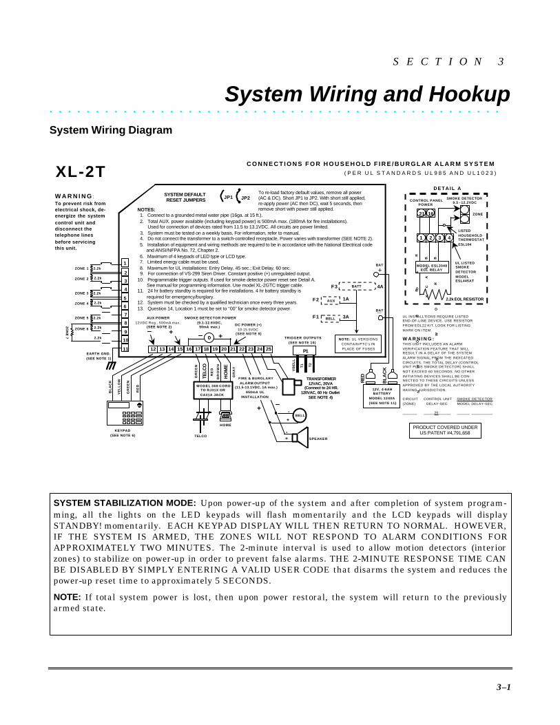
System Wiring Diagram
SYSTEM STABILIZATION MODE: Upon power-up of the system and after completion of system program-ming, all the lights on the LED keypads will flash momentarily and the LCD keypads will displaySTANDBY! momentarily. EACH KEYPAD DISPLAY WILL THEN RETURN TO NORMAL. HOWEVER,IF THE SYSTEM IS ARMED, THE ZONES WILL NOT RESPOND TO ALARM CONDITIONS FORAPPROXIMATELY TWO MINUTES. The 2-minute interval is used to allow motion detectors (interiorzones) to stabilize on power-up in order to prevent false alarms. THE 2-MINUTE RESPONSE TIME CANBE DISABLED BY SIMPLY ENTERING A VALID USER CODE that disarms the system and reduces thepower-up reset time to approximately 5 SECONDS.
NOTE: If total system power is lost, then upon power restoral, the system will return to the previouslyarmed state.
D E T A I L A
21 16
1 2 3 4
ZONE
CONTROL PANELPOWER
SMOKE DETECTOR9.5 - 12.2VDC
LISTED
HOUSEHOLD THERMOSTAT
ESL104
MODEL ESL2048 EOL RELAY
RE
D
BL
AC
K
BR
OW
N
BR
OW
N
2.2k EOL RESISTOR
UL LISTED SMOKE
DETECTOR
MODEL ESL445AT
UL INSTALLTIONS REQUIRE LISTEDEND-OF-LINE DEVICE. USE RESISTORFROM EOL22 KIT. LOOK FOR LISTINGMARK ON ITEM.
W A R N I N G :THIS UNIT INCLUDES AN ALARMVERIFICATION FEATURE THAT WILLRESULT IN A DELAY OF THE SYSTEMALARM SIGNAL FROM THE INDICATEDCIRCUITS. THE TOTAL DELAY (CONTROLUNIT PLUS SMOKE DETECTOR) SHALLNOT EXCEED 60 SECONDS. NO OTHERINITIATING DEVICES SHALL BE CON-NECTED TO THESE CIRCUITS UNLESSAPPROVED BY THE LOCAL AUTHORITYHAVING JURISDICTION.
CIRCUIT CONTROL UNIT SMOKE DETECTOR(ZONE) DELAY-SEC MODEL DELAY-SEC
_______ _____20______ ______ __________
PRODUCT COVERED UNDERUS PATENT #4,791,658
NOTES: 1. Connect to a grounded metal water pipe (16ga. at 15 ft.). 2. Total AUX. power available (including keypad power) is 500mA max. (180mA for fire installations). Used for connection of devices rated from 11.5 to 13.1VDC. All circuits are power limited. 3. System must be tested on a weekly basis. For information, refer to manual. 4. Do not connect the transformer to a switch-controlled receptacle. Power varies with transformer (SEE NOTE 2). 5. Installation of equipment and wiring methods are required to be in accordance with the National Electrical code and ANSI/NFPA No. 72, Chapter 2. 6. Maximum of 4 keypads of LED type or LCD type. 7. Limited energy cable must be used. 8. Maximum for UL installations: Entry Delay, 45 sec.; Exit Delay, 60 sec. 9. For connection of VS-299 Siren Driver. Constant positive (+) unregulated output.10. Programmable trigger outputs. If used for smoke detector power reset see Detail A. See manual for programming information. Use model XL-2GTC trigger cable.11. 24 hr battery standby is required for fire installations. 4 hr battery standby is required for emergency/burglary.12. System must be checked by a qualified technician once every three years.13. Question 14, Location 1 must be set to ‘’00” for smoke detector power.
W A R N I N G :To prevent risk from
electrical shock, de-
energize the system
control unit and
disconnect the
telephone lines
before servicing
this unit.
SYSTEM DEFAULT RESET JUMPERS
TRANSFORMER12VAC, 20VA
(Connect to 24 HR.120VAC, 60 Hz Outlet
SEE NOTE 4)
+
-
SPEAKER
-+
+
SMOKE DETECTOR POWER
(9.1-12.6VDC,50mA max.)
BELL
DC POWER (+)
10-15.5VDC(SEE NOTE 9)
KEYPAD
(SEE NOTE 6)
BL
AC
K
YE
LL
OW
GR
EE
N
RE
D
FIRE & BURGLARY
ALARM OUTPUT (11.5-13.1VDC, 1A max.)
650mA UL
INSTALLATION
HOME
TELCO
BR
OW
N
GR
AY
HO
ME
GR
EE
N
RE
D
TE
LC
O
MODEL 368 CORD TO RJ31X OR
CA31A JACK
AUX POWER
12VDC Reg., 500mA max. (SEE NOTE 2)
+
ZO
NE
7
2.2k
2.2k
ZONE 1
ZONE 2
2.2kZONE 5
1
7
6
5
4
3
2
2.2k
EARTH GND.
(SEE NOTE 1)
8
9
10
11
2.2k
2.2k
ZONE 3
ZONE 4
ZONE 6
+
_
JP1 JP2To re-load factory default values, remove all power(AC & DC). Short JP1 to JP2. With short still applied,re-apply power (AC then DC), wait 5 seconds, thenremove short with power still applied.
25 19 20 21 22 23 24 12 13 14 15 16 17 18
+2.2k
BELL
AUX
VB
EL
L
T1 T2
P1
XL-2TC O N N E C T I O N S F O R H O U S E H O L D F I R E / B U R G L A R A L A R M S Y S T E M
( P E R U L S T A N D A R D S U L 9 8 5 A N D U L 1 0 2 3 )
TRIGGER OUTPUTS
(SEE NOTE 10)
BL
AC
K
RE
D
12V, 4-6AHBATTERY
MODEL 1240A
(SEE NOTE 11)
BAT
BAT
BATT
F1 3A
NOTE: UL VERSIONSCONTAIN PTC’s INPLACE OF FUSES
F2 1A
F3 4A
XL-2T Installation & Setup Guide
3–2
Terminal ConnectionsTERMINALS DESCRIPTION1(+) & 2(-) Zone 1 (Requires 2.2K EOL resistor) [Default = DELAY]3(+) & 2(-) Zone 2 (Requires 2.2K EOL resistor) [Default = INTERIOR]4(+) & 5(-) Zone 3 (Requires 2.2K EOL resistor) [Default = PERIMETER]6(+) & 5(-) Zone 4 (Requires 2.2K EOL resistor) [Default = PERIMETER]7(+) & 8(-) Zone 5 (Requires 2.2K EOL resistor) [Default = PERIMETER]9(+) & 8(-) Zone 6 (Requires 2.2K EOL resistor) [Default = PERIMETER]10(+) & 8(-) Zone 7 (Requires 2.2K EOL resistor) [Default = Normally Open (N/O)
PANIC]ZONE INFORMATION:
Normally closed (N/C) devices may be wired in series; and/or normally open(N/O) devices wired in parallel, with the 2.2K ohm EOL resistor on allzones (refer to System Wiring Diagram on page 3-1). However, the N/O andN/C loops may be wired without the EOL resistors, depending upon howthe zone(s) are programmed.
The standard loop response time is 280mSec on all zones. The factory de-fault function for each zone is listed in the table above; however, any zonecan be programmed for the following types of operation: Delay, Perimeter,Interior, Fire, 24-Hr. Alarm, or 24-Hr. Trouble. Further explanation of thezone types can be found in Section 6: System Programming.
NOTE: Loop response time is defined as the minimum time required for afault to trip a zone.
8 & 10 ZONE 7:Defaulted to normally open PANIC circuit. This hardwired panic is a 24-hour zone that can be programmed for silent or audible operation. Thepanic circuit will activate with each violation; therefore, a latched device isnot recommended. A momentary device is recommended. This zone, as theother six zones, is fully programmable (see Question 23, Locations 1 and 2).
For UL installations, the panic switch connected to these terminals is to belocated no more than 3 feet from the control unit, with no intervening bar-riers (this is a supervision requirement only).
11 EARTH GROUND:Connect this terminal to a cold water pipe using 16AWG wire for a distancenot greater than 15 feet. Use a non-corrosive metal strap firmly secured tothe pipe to which the wire is electrically connected and secured. If thepremises pipes terminate in PVC, this terminal must be connected directlyto a six-foot grounding rod.
12, 13, 14, 15 KEYPADS (See notes on page 1-2):A maximum of 4 keypads of the following types may be used: XK-406, XK-4600RM, XK-4600SM, 6615 (non-addressable LED display type); or XK-508(addressable LED display type); or XK-5LC, XK-7LC (addressable LCDdisplay type).The connections are as follows:12 (BLACK = negative), 13 (YELLOW = data in), 14 (GREEN = data out),and 15 (RED = positive). Each keypad draws approximately 30mA. Maxi-mum keypad wire run distance is 500 feet using 22-gauge wire.
Do NOT wire addressable and non-addressable keypads in the same in-stallation.
NOTE: In some installations, it may be necessary to use shielded wire toprevent radio frequency interference.
Section 3 - System Wiring and Hookup
3–3
12(-) & 15(+) AUXILIARY POWER:The total regulated output power available at these terminals for connec-tion of motion detectors and other external devices is 500mA at 11.5 –13.1VDC with less than 100mVpp ripple. If the total drain on these ter-minals exceeds the 500mA limit, use a second power supply. Refer to theAuxiliary Device Current Draw Worksheet later in this section for deter-mining total current draw.
21(+) & 16(-) SMOKE DETECTOR POWER:This system will accept 9.5-12VDC RANGE RATED FOUR-WIRESMOKE DETECTORS ONLY. Approximately 50mA of current is avail-able at these terminals for powering all detectors and an EOL relay FBIImodel 620. For UL installations, see wiring diagram for hookup.
NOTE: Trigger #1 must be selected for smoke detector power reset in or-der for this feature to activate.
These terminals adhere to the fire verification and reset logic, which isexplained in the zone types section (Questions 17 - 23) in Section 6: Sys-tem Programming. Manual reset of smoke detector power can be ac-complished by entering a valid user code after clearing alarm memory, orby using the star (T) key.
17, 18, 19, 20 TELEPHONE LINE:Connect the model 368 cord as follows: 17 (GREEN = Telco Tip),18 (RED = Telco Ring), 19 (BROWN = Home Tip), 20 (GRAY = HomeRing). Insert the plug into a USOCRJ31X jack (or a CA31A jack for Ca-nadian installations).
The FCC registration number is (AE398E-69554 AL-E), and the ringerequivalence is (0.0B). The system should not be connected to party linesor coin-operated phones.
If this control panel will be used for uploading, downloading, or remote command applications,the telephone line connected to the control panel MUST NOT be shared with a fax machine ormodem. Furthermore, this device should not be connected to a phone line that has Call Waiting,unless the Call Waiting interrupt numbers are programmed into the panel dialing sequence.
21(+) CONSTANT DC POWER:This terminal delivers unregulated 10.0-15.5VDC power for devices re-quiring power within that voltage range, such as a VS279. The terminalis protected by a Power Thermal Cutoff (PTC), which acts as an in-linecircuit breaker for those times when excess current is drawn. The PTCdoes not require replacement after operation; it will reset itself after anominal time delay.
NOTE: Power for these devices can also be obtained by splicing the RED(+) battery lead with an in-line fuse rated at 3 Amps or a PTC (for ULversions).

XL-2T Installation & Setup Guide
3–4
22(+) & 23(-) BELL OUTPUT:The total output power available for sounding devices is 1 amp at 10.5 -15.5VDC for residential applications, or 12.0 - 14.4VDC for commercialinstallations (650mA for UL installations). These terminals will deliverCONSTANT output on BURGLARY, AUDIBLE PANIC, and BELLTEST. On a FIRE condition, a PULSED output will be generated.There are separate bell cutoff times programmable for burglary and fireconditions within the programming sequence.
UL For UL Household Fire Warning System installations, the speaker must be mounted indoors forbest audibility. Also, for UL installations, use only one speaker.
NOTE: Before connecting sounding devices, refer to their individualspecification sheets to determine current draw. Otherwise, the PTC maycause continuous circuit interruption. An option exists to supervise thebell output terminals if any zone is programmed as a fire zone (see Pro-gram Questions 17–23); refer to the following information.
NFPA 72 REQUIREMENT: All the inter-connecting pathways (cable, wire, etc.)between the alarm system initiatingdevice (control panel) and the signalingdevice (bell, speaker, siren, etc.) shallbe monitored for an occurrence of anopen circuit, which prevents the normaloperation of the system. An occurrenceof an open circuit shall be indicated by adistinctive trouble signal.
BELL SUPERVISION (Bell) - To meet the NFPA 72 requirement, pro-gram any zone as a Fire Zone (Program Question 22, Locations 1 and 2).The bell is then supervised for an open circuit (not a short circuit) acrossthe bell output terminals; the keypad will indicate that a fire troublecondition has occurred and fire trouble is reported to the CS if enabled(Program Question 32, Location 3). If the bell is already ringing, the su-pervision will not take effect until after bell cutoff time. Refer to the fol-lowing diagram:
SIREN SUPERVISION (Self-Contained Siren/Speaker) - (Not for use inUL installations.) To meet the NFPA 72 requirement, program any zoneas a fire zone (Program Question 22, Location 1). The siren is then super-vised for an open circuit (not a short circuit) across the bell output termi-nals; the keypad will indicate that a fire trouble condition has occurredand fire trouble is reported to the CS if enabled (Program Question 32,Location 3). If the siren is already sounding, the supervision will not takeeffect until after bell cutoff time.NOTE: Use FBII models ZR-815C, ZR-815EC, or ZR-830EC. Refer to thefollowing diagram:
Siren/Speaker
22 (+)
23 (-)
Bell Output
Mechanical Bell
22 (+)
23 (-)
Bell Output
Section 3 - System Wiring and Hookup
3–5
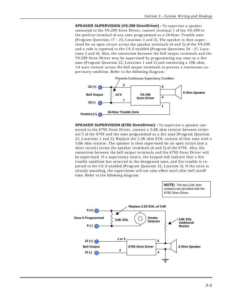
SPEAKER SUPERVISION (VS-299 Siren/Driver) - To supervise a speakerconnected to the VS-299 Siren Driver, connect terminal 1 of the VS-299 tothe positive terminal of any zone programmed as a 24-Hour Trouble zone(Program Questions 17 - 23, Locations 1 and 2). The speaker is then super-vised for an open circuit across the speaker terminals (4 and 5) of the VS-299and a code is reported to the CS if enabled (Program Questions 24 - 27, Loca-tions 3 and 4). Also, the connection between the bell output terminals and theVS-299 Siren Driver may be supervised by programming any zone as a firezone (Program Question 22, Locations 1 and 2) and connecting a 10K ohm,1/4 watt resistor across the bell output terminals to prevent a continuous su-pervisory condition. Refer to the following diagram:
SPEAKER SUPERVISION (679S Siren/Driver) - To supervise a speaker con-nected to the 679S Siren Driver, connect a 5.6K ohm resistor between termi-nal 5 of the 679S and the zone programmed as a fire zone (Program Question22, Locations 1 and 2). Replace the 2.2K ohm EOL resistor of that zone with a5.6K ohm resistor. The speaker is then supervised for an open circuit (not ashort circuit) across the speaker terminals (4 and 5) of the 679S. Also, theconnection between the bell output terminals and the 679S Siren Driver willbe supervised. If a supervisory occurs, the keypad will indicate that a firetrouble condition has occurred in the designated zone, and fire trouble is re-ported to the CS if enabled (Program Question 32, Location 3). If the siren isalready sounding, the supervision will not take effect until after bell cutofftime. Refer to the following diagram:
NOTE: The two 5.6K ohmresistors are provided with the679S Siren Driver.
VS-299Siren Driver
8 Ohm Speaker
5
4
2
7
22 (+)
23 (-)
Bell Output
24-Hour Trouble Zone
1
Positive (+)
10 K
Prevents Continuous Supervisory Condition
9 (+)
8 (-)
679S Siren Driver
Zone 6 Programmed5.6K EOL
8 Ohm Speaker
5.6K EOLAdditionalResitor
5
4
1 or 3
2
SmokeDetector
Replace 2.2K EOL w/ 5.6K
22 (+)
23 (-)
Bell Output

XL-2T Installation & Setup Guide
3–6
24 & 25 TRANSFORMER:
Connect the 12VAC, 40VA transformer output using 16AWG wire. Installit not further than 15 feet from the control panel. Plug the transformerinto an unswitched 120VAC outlet.
Do not use any other transformer as this may result in improper operation or damage to the unit.
The AC/LOW BAT LED on the keypad will remain ON while AC power ispresent. If an AC loss occurs, the AC/LOW BAT LED will turn OFF im-mediately. If AC remains OFF for 15 minutes, the system will turn ONthe keypad sounder and transmit to the Central Station (CS), if pr o-grammed. Refer to Questions 28 and 29, locations L3 and L4 to enable ei-ther transmission. The keypad sounder is enabled in Question 12, L4 andis silenced by entry of any valid user code. When AC is restored, theAC/LOW BAT LED will light immediately, and a restore code will be re-ported, if pr ogrammed in Question 28, L3 and L4.
BACKUP BATTERY: The RED(+) and BLACK(-) flying leads coming out of the lower right sideof the control panel must be connected to a 12VDC, 4-6AH Sealed LeadAcid battery to serve as backup power in the event of AC loss.A battery test occurs approximately every 4.5 minutes. Low battery con-dition occurs at a nominal 11VDC. The keypad AC/LOW BAT LED andbuzzer will PULSE SLOWLY when a low battery condition is detected.The system reports this condition to the CS if programmed in Question28, L3. The buzzer may be silenced by entry of any valid user code. Afterreplacement, the backup battery is again automatically tested for ade-quate output every 4.5 minutes.
UL For UL installations, use two 4AH batteries connected in parallel.
GROUND START: Ground start capability can be added to the system through addition ofthe FBII Model 117 Module. Refer to the 117 Installation Instructions forhookup information. With this device, some systems can obtain dial tonein areas that do not automatically provide dial tone. At the moment tele-phone line seizure occurs, the Telco Tip is momentary connected to earthground to access dial tone.
UL The 117 Module has not been tested for use in UL installations.
TRIGGER OUTPUTS (1 & 2): The control panel contains two programmable trigger outputs. Trigger #1terminals are P1VBELL(+) and P1T1(-). Trigger #2 terminals areP1VBELL(+) and P1T2(-). See Programming Question 14 for valid triggertypes.
TRIGGER #1 can be enabled for smoke detector power, which can alsobe obtained from terminals 15(+) and 16(-).
TRIGGER #2 CANNOT be selected for smoke power.
In order to connect devices to the triggers, use connector XL-2G TC (trig-ger cable). The trigger outputs are selectable for inverted or non-invertedoperation. Connect to terminal P1 VBELL to obtain a POSITIVE refer-ence point.
ULFor UL installations, the trigger outputs shall be connected to devices rated to operate within therange of 10.1 - 14.0VDC at 50mA.

Section 3 - System Wiring and Hookup
3–7
Auxiliary Device Current Draw WorksheetDEVICE TYPES CURRENT DRAW FOR
EACH DEVICENUMBER OF
UNITSTOTAL CURRENT FOR
EACH DEVICE TYPEXK-406 Keypad 60mA *XK-4600RM Keypad 30mA *XK-4600SM Keypad 30mA *6615 Keypad 60mA *XK-508 Keypad 65mA *XK-5LC Keypad 65mA *XK-7LC Keypad 65mA *PIR **Smoke Detector **Glassbreak Detector **
TOTAL CURRENT FOR ALL DEVICES =(500mA max.)***
* Only applies if device is powered from control terminals 15 (+) and 12 (-).** If you are using devices such as PIR's, smoke detectors, etc., refer to the specifications for that particular device's
current draw. If the total current draw exceeds 500mA, use an additional power supply.*** For UL installations, do not exceed 180mA.
Wiring Information for Keypads and Other DevicesIf single or multiple devices are connected to a single 4-wire or 2-wire run ("daisy chained")to the control terminals, determine the current drawn by the unit(s) connected to the singlewire run, then refer to the Wiring Run Table below to determine the maximum wire lengththat can be safely used for each wire size.In some cases, the total current drawn may result in a value not shown in the table. For ex-ample, if you plan to use #22 gauge wire and the total current drawn is 400mA (a value be-tween 300mA and 500mA), the maximum wire length you should use is approximately 65 ft.(a length between 50 and 80 ft.). Other maximum wire lengths for values of current notshown in the table can be calculated in a similar manner.Maximum wire lengths for a device that is "home run" to the control can also be determinedfrom the table, based on the current draw of that device alone.
Wiring Run Table for Devices Drawing Power From Terminals 15 (+) & 12 (-)
TOTAL CURRENT DRAWN BY ALL UNITS ON A SINGLE WIRE RUNWIRE SIZE
50mA or less 100mA 300mA 500mA#22 500 ft. (152m) 250 ft. (76m) 80 ft. (24m) 50 ft. (15m)#20 750 ft. (228.6m) 380 ft. (116m) 130 ft. (39.6m) 80 ft. (24m)#18 1300 ft. (396m) 650 ft. (198m) 220 ft. (67m) 130 ft. (39.6m)#16 2000 ft. (609.6m) 1000 ft. (305m) 330 ft. (100.5m) 200 ft. (70m)
Examples:1. What is the maximum distance from the control panel for one XK-4600SM keypad
drawing 30mA using #20 gauge wire?Using the table above, the keypad can be placed no farther than 750 ft. away from thepanel (50mA or less).
2. What is the maximum distance for 3 keypads (one XK-4600SM and two 6615) drawing150mA (30mA + 60mA + 60mA) using #20 gauge wire connected in a single wire run?
Using the tables above, the farthest keypad can be placed no more than 317.5 ft. awayfrom the panel. (380-130=250; 250÷2=125; 130+125=255 ft for 200mA; then 380-255=125;125÷2=62.5; 62.5+255=317.5 ft)
3. What is the maximum distance for 5 smoke detectors drawing 0.25mA (50 microA each)using #22 gauge wire connected in a single wire run?
Using the table above, the farthest smoke detector can be placed no more than 500 ft.away from the panel.

XL-2T Installation & Setup Guide
3–8
4–1
S E C T I O N 4
Keypad Features• • • • • • • • • • • • • • • • • • • • • • • • • • • • • • • • • • • • • • • • • • • • • • • • •
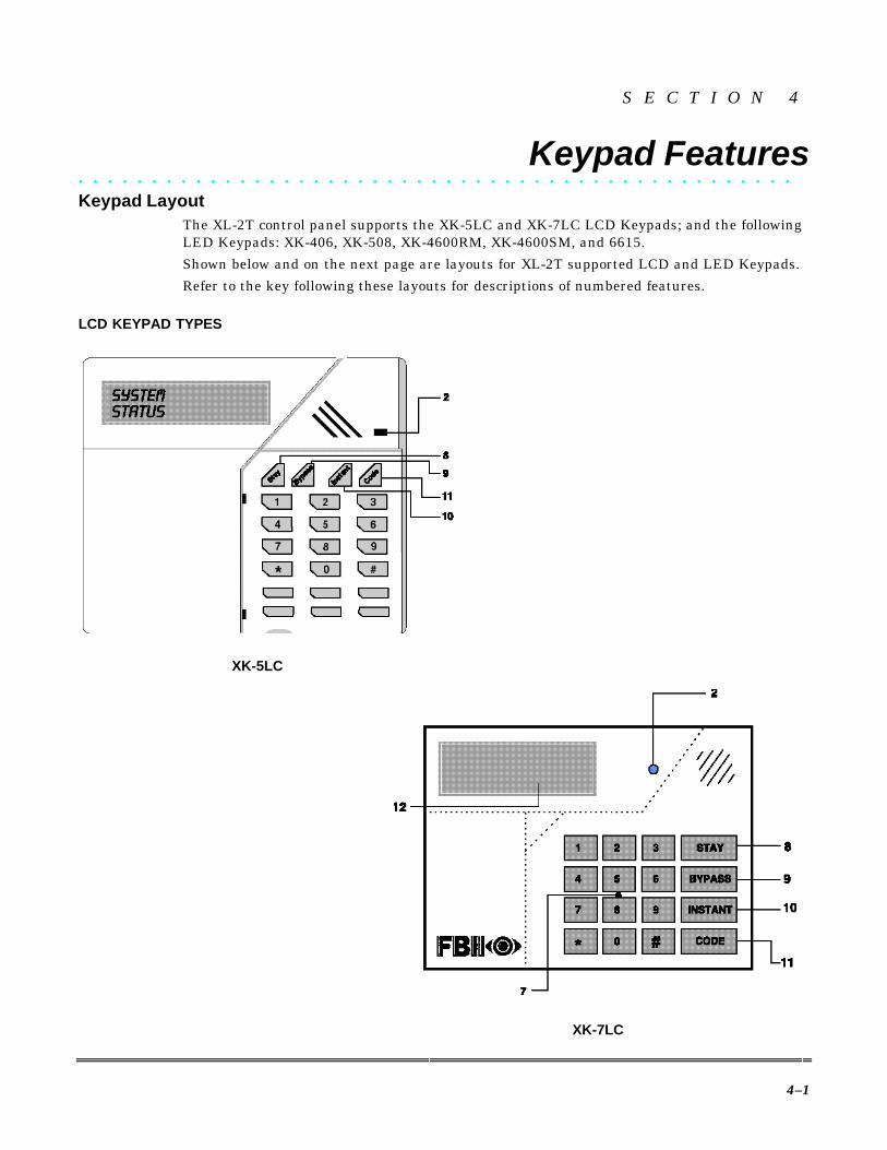
Keypad LayoutThe XL-2T control panel supports the XK-5LC and XK-7LC LCD Keypads; and the followingLED Keypads: XK-406, XK-508, XK-4600RM, XK-4600SM, and 6615.Shown below and on the next page are layouts for XL-2T supported LCD and LED Keypads.Refer to the key following these layouts for descriptions of numbered features.
LCD KEYPAD TYPES
XK-5LC
XK-7LC

XL-2T Installation & Setup Guide
4–2
LED KEYPAD TYPES
XK-4600SM
6615
XK-4600RM
XK-508
XK-406

Section 5 - System Operation
4–3
1 - ZONE STATUS LEDSThese LEDs display the current zone status, including alarms, bypasses, and faults.Each condition will cause these LEDs to operate differently, as follows:
ALARMS Fast Blink (approx. 150mS ON - 150mS OFF).
TROUBLES Slow Pulse (approx. 600mS ON - 600mS OFF).
BYPASSES Blink (100mS ON - 900mS OFF). Zone bypasses are displayed as a veryslow blink of the zone LED light.
FAULTED ZONES Solid ON. Faulted zones are the lowest-priority indication.Faulted burglary zones are displayed with the LED solidly ON while the system is dis-armed.
NORMAL OFF.
Upon entry, the keypad sounder will annunciate to warn the user to disarm the system. In addi-tion, the respective zone LED(s) will be ON to indicate zones that are violated (e.g., entry doorand motion detector).
2 - ARM LEDThis LED indicates that the system is currently armed (ON) or disarmed (OFF).
Fast Blink Alarm mode (alarms have occurred).Slow Blink Unable to communicate with Central Station.
3 - STAY LEDThis LED indicates that the system has been armed in the STAY, STAY/INSTANT, orAUTO STAY mode. If the INSTANT LED is ON and the STAY LED is ON, then the sys-tem is in the STAY/INSTANT mode. If the INSTANT LED is OFF and the STAY LED isON, then the system is in the STAY mode only. STAY/INSTANT is enabled in Program-ming Question 05, Location 4. In either mode, the STAY LED indicates the following:
ON Interior zones are bypassed.OFF Interior zones are normal.
4 - INSTANT LEDThis LED indicates that the system has been armed in the INSTANT or STAY/INSTANTmode, meaning that the system is currently armed, all delay zones are instant, and allinterior zones are bypassed. If the STAY LED is OFF and the INSTANT LED is ON,then the system is in the INSTANT mode. If the STAY LED is ON and the INSTANTLED is ON, then the system is in the STAY/INSTANT mode.
NOTE: See Programming Question 12, Location 3.
ON Delay zones are currently instant.OFF Delay zones are normal.
5 - AC/LB LEDThis LED displays the current power status of the panel, as follows:
ON AC is present.OFF No AC; running on battery backup.Slow Blink Low battery condition detected.
6 - READY LEDThis LED indicates that the system is ready for arming. The READY LED is common toall BURGLARY ZONES, with the following indications:
ON System ready to be armed.OFF System not ready to be armed.Slow Blink Indicates Installer programming mode.Fast Blink Alarm memory mode.

XL-2T Installation & Setup Guide
4–4
7 - COM LEDThis LED indicates that communication between the panel and Central Station (CS) isbeing maintained.
Slow Blink Communication failure.OFF Normal operation - communication active.
8 - STAY BUTTONThe STAY button arms the system, excluding zones programmed as interior zones. Thisprovides exterior protection of the premises while allowing full access throughout the in-terior.
9 - BYPASS BUTTONThe BYPASS button is used to temporarily exclude protection to a specific zone(s).
10 - INSTANT BUTTONIf pressed, the INSTANT button allows arming the system in the INSTANT mode. Withthe STAY button, it enables arming the system in the STAY/INSTANT mode.
NOTE: INSTANT mode is enabled in Question 12, Location 3.11 - CODE BUTTON
The CODE button is used to allow entry into the installer programming mode and per-mits the master user to program other user codes.
12 - LCD DISPLAY (XK-7LC AND XK-5LC KEYPADS ONLY)The LCD panel displays the current system status in a two-line by sixteen-characterformat.
13 - KEYPAD AUXILIARY KEYS (XK-4600SM KEYPAD ONLY)Pressing the two keys (top and bottom) labeled P, A, or F at the same time initiates a CStransmission, if programmed, of PANIC, AUXILIARY, or FIRE, causes annunciation ofthe keypad sounder, and turns on the bell output. If not programmed to transmit, press-ing these keys will result only in a local warning, as follows (see Question 07, Location 3):
Keypad Sounder - Steady for PANIC, pulsing for FIRE and AUXILIARY.Bell Output - Steady for PANIC, pulsing for FIRE.
See the Keypad Emergency Conditions in Section 5: System Operation for alternate auxiliarykeys.
System Mode Summary
LEDsMODE ARM STAY INSTANT AC/LB READY
STAY ARMED ON ON Slow blink
AUTO STAY ARMED ON ON Slow blink
STAY/INSTANT ARMED ON ON ON Fast blink
AUTO STAY/INSTANT ARMED ON ON ON Fast blink
INSTANT ARMED ON ON Fast blink
ARMED
(all burglary zones armed)ON
AC present(Steady ON)
No ACRunning on
batterybackup(Steady
OFF)Low
Battery(Slow blink)
OFF

Section 5 - System Operation
4–5
Keypad Sounder
The sounder (or loudspeaker) housed inside the keypad emits sounds according to the condi-tion of the security system.
The keypad sounder annunciates differently to indicate the following conditions:
CHIRP - Keypad sounds a short chirp to confirm each keystroke.
STEADY - The keypad makes a steady sound during entry time and/or during burglaryalarm.
CHIME - A steady 1-second tone indicates the system is disarmed.
ACKNOWLEDGE - Upon successful entry of certain commands, the system will sound forapproximately half a second.
PULSING - A pulsing sound (approximately half a second ON, then OFF) indicates a troublecondition such as AC loss, low battery, or fire zone.
NEGATIVE ACKNOWLEDGMENT - Upon entry of an illegal command, the keypad willsound four short beeps. For example, if you are attempting to define a new user, and themaster user is not entered, four short beeps will be made indicating that the command wasunsuccessful.
SOUNDER RINGBACK - Several short beeps indicate successful communication to theCentral Station. This occurs for all signals, excluding ambush and silent zones.
FAST PULSING SOUNDER - Sound generated during entry time period AFTER an alarmcondition has occurred and the system reached bell cutoff. A pulsing sounder will follow thebell output on fire conditions. Trouble conditions also generate a pulsing sound and may besilenced through entry of a valid user code.
The keypad is NOT operational if none of the LEDs are lit and the keypad does not beep whenkeys are pressed. This is an indication that service is required. Refer to Appendix B: Trouble-shooting.
Keypad Addressing(XK-508 (LED type) and XK-5LC, XK-7LC (LCD types) ONLY)
Both versions of keypads (LED model XK-508 and LCD models XK-5LC and XK-7LC)contain switches to set the address of the keypad. This address will identify the keypadnumber to the control panel.
On XK-508 and XK-5LC keypads, the address switches are located at the bottom, left insideof the front section. To access these switches, separate the front and back portions of thekeypad by inserting a slot screwdriver into one of the two slots at the bottom of the keypadand twisting. Repeat for the other slot. The protective cover for the address switches is re-moved as part of the rear portion of the keypad. The address switches are now exposed andadjustable.
The address switches for XK-7LC keypads are located just behind the pull-open door.
The address switch positions for the keypads are shown below:

XL-2T Installation & Setup Guide
4–6
On XK-508 and XK-5LC keypads, when the switch is pushed toward the back of the keypad(in the direction of the arrow above), the switch is in the ON position. When the switch ispushed toward the front of the keypad (in the opposite direction of the arrow), the switch isin the OFF position.
ON
On the XK-7LC keypad, when the right-hand side of the address switch is pushed inward,the switch is in the ON position. When the left-hand side of the switch is pushed inward, theswitch is in the OFF position.Set the first three switches (SW1 - SW3) as follows:
KEYPADNUMBER SW1 SW2 SW3 SW4*
1 ON ON ON *2 OFF ON ON *3 ON OFF ON *4 OFF OFF ON *5 ON ON OFF *6 OFF ON OFF *7 ON OFF OFF *8 OFF OFF OFF *
*Set switch SW4 as follows: ON for sounder OFF; OFF for sounder ON
• Keypads of the same type shall not be set with identical addresses. An XK-508 and an XK-5LC may be set to the same address number (because one is an LED type and the other anLCD type and both addressable).
• The control panel supports up to four keypads.
1 2 3 4ON
XK-508 AND XK-5LC (BOTTOM VIEW WITH BACK REMOVED)
XK-7LC FRONT VIEW (WITH COVER OPEN)
2
3
4
1

5–1
S E C T I O N 5
System Operation• • • • • • • • • • • • • • • • • • • • • • • • • • • • • • • • • • • • • • • • • • • • • • • • •
Power-Up/System ResetSYSTEM STABILIZATION MODE: Upon power-up of the system and after completion ofsystem programming, IF THE SYSTEM WAS PREVIOUSLY ARMED, all the lights on theLED keypad(s) will turn ON momentarily or, in the case of an LCD display installation, thekeypad(s) will display STANDBY! momentarily. The keypad display will then return tonormal. However, the zones will not respond to alarm conditions for approximately 2 min-utes. This 2-minute delay can be disabled by simply entering a valid user code that disarmsthe system and reduces the power-up reset time to approximately 5 seconds. The 2-minuteinterval is used to allow motion detectors (interior zones) to stabilize in order to prevent falsealarms. Upon system power-up, IF THE SYSTEM WAS PREVIOUSLY DISARMED, thepower-up reset time will be approximately 5 seconds. If total system power is lost, uponpower restoral the system will return to its previously armed state.
Arming the SystemThe system can be armed only if ALL burglary zones are not faulted.On LED display keypads, this requires that the READY LED be ON.On LCD display keypads, the following message will appear:
TO ARM: Enter any programmed four-digit user code.NOTE: The factory default for user #1 is 1234.The ARMED LED will light and the user may exit through an exit/entry zone for the timeperiod programmed as the exit delay.
LCD display keypads will indicate the following message:
The system can be armed without the backup battery being connected; however, the AC/LBor BAT light will flash, depending on the keypad used.
Stay ArmingTO ARM: Press the STAY key and then enter a four-digit user code.This will arm the system with all programmed interior zones excluded.
On LED display keypads, the STAY and ARM LEDs will light continuously.
LCD display keypads will indicate the following message:
SYSTEM: READY
ON: AWAYEXIT NOW
ON: STAYEXIT NOW

XL-2T Installation & Setup Guide
5–2
Instant ArmingTO ARM: Press the INSTANT key followed by a four-digit user code. The INSTANT andARM LEDs will light continuously.
LCD display keypads will indicate the following message:
The entire security system (interior and exterior) is armed at this time, allowing only for theentry/exit time delay that has been programmed into the system.
NOTE: The INSTANT mode can be enabled through Programming Question 12, Location 3.
Stay/Instant ArmingTO ARM: Press the STAY key; press the INSTANT key and enter a four-digit user code.
The STAY/INSTANT mode will arm the system with the characteristics of both the STAYand INSTANT modes. The keypads will have the ARM, INSTANT, and STAY LEDs turnedON continuously.
LCD display keypads will indicate the following message:
The system will be armed with the interior zones bypassed and the delay zones INSTANT after the programmed entry/exit time.
NOTE: The STAY/INSTANT mode can be enabled through Programming Question 12, L3.
System Mode SummaryLEDs
MODE ARM STAY INSTANT AC/LB READYSTAY ARMED ON ON Slow blink
AUTO STAY ARMED ON ON Slow blink
STAY/INSTANT ARMED ON ON ON Fast blink
AUTO STAY/INSTANT ARMED ON ON ON Fast blink
INSTANT ARMED ON ON Fast blink
ARMED
(all burglary zones armed)ON
AC present(Steady ON)
No ACRunning on
batterybackup(Steady
OFF)Low
Battery(Slow blink)
OFF
DisarmingTO DISARM: Enter any valid four-digit user code and the ARM LED will extinguish.If an alarm condition exists or occurred while the system was armed, the respective zoneLED will blink rapidly. On the LED keypads, the READY LED will also blink rapidly. Thiscondition is classified as alarm memory, and can be cleared by entering a valid user codeagain.
ResetReset is accomplished through the entry of any valid user code. This can be used to reset thesmoke detectors attached to the system, silence any bells or sounders, or clear the keypaddisplay. In addition, the star key [Q] acts as a reset for clearing alarm and fire memory whenthe security system is not armed.
Bypass by Zone/GroupBypassing is enabled to temporarily exclude zones or sensors that are faulty, or otherwisenot ready for operation, from activating the security system.
ON: AWAY INSTANT
ON: STAY INSTANT

Section 5 - System Operation
5–3
If QUICK BYPASS is disabled (Question 08, Location 3) and ZONE BYPASS is enabled(Question 17-23, Location 3), then:
TO BYPASS BY ZONE: Press the BYPASS key followed by any valid 4-digit user code, fol-lowed by a single-digit number (1-7) representing the zone to be bypassed. The LED and LCDkeypads are programmed for BYPASS in the same way, only the displays are different.
EXAMPLE: To bypass Zone 6 (assuming user code of 1234), press [BYPASS] + [1234] + [6].
If QUICK BYPASS is disabled (Question 08, Location 3), ZONE BYPASS is enabled (Ques-tion 17-23, Location 3) and BYPASS BY GROUP is enabled (Question 09, Location 1), then:
TO BYPASS BY GROUP: Disable QUICK BYPASS and press the BYPASS key followed byany valid 4-digit user code, followed by the [#] key, which represents the group of zones to bebypassed.
NOTE: Bypassing a group will remove only the individual zones enabled for that group.
EXAMPLE: To bypass a group, press [BYPASS] + [1234] + [#].
Quick Bypass by Zone/GroupQuick Bypassing is a programmable option (Question 08, Location 3) and allows the user tobypass zones without using a user code.
If QUICK BYPASS is enabled (Question 08, Location 3) and ZONE BYPASS is enabled(Question 17-23, Location 3), then:
TO BYPASS BY ZONE: Press the BYPASS key followed by a single-digit number (1-7) rep-resenting the zone to be bypassed.EXAMPLE: To bypass Zone 6, press [BYPASS] + [6].
If QUICK BYPASS is enabled (Question 08, Location 3), ZONE BYPASS is enabled (Ques-tion 17-23, Location 3), and BYPASS BY GROUP is enabled (Question 09, Location 1), then:
TO BYPASS BY GROUP: Press the BYPASS key followed by the [#] key, representing thegroup of zones to be bypassed.EXAMPLE: To bypass a group, press [BYPASS] + [#].
NOTE: Bypassing a GROUP will remove only the individual zones enabled for that group.
After a successful bypass, the keypad sounder will emit the acknowledge beep and the re-spective zone LED will BLINK SLOWLY; or, on LCD keypads, the following message will bedisplayed:
In addition, note the following rules for bypass:• Fire zones cannot be bypassed.• 24-hour zones can be bypassed; however, they CANNOT be unbypassed if they are
violated.• Zones can be bypassed only while the system is disarmed, at which time visual indica-
tion is displayed.
Bypass signals will be transmitted to the Central Station (CS) UPON ARMING if a bypasscode has been programmed.
Zones that are bypassed are not protected when the system is armed.
BYPASSZONE 1, 2

XL-2T Installation & Setup Guide
5–4
Auto UnbypassAll burglary zones that are bypassed are automatically unbypassed upon system disarm.Twenty-four-hour zones that have been bypassed will be unbypassed only if they are notvalidated.
Manual UnbypassMANUAL UNBYPASS removes an existing bypass from a currently bypassed zone or group.The procedure is the same as for bypass.
KEYPAD TAMPER/LOCKOUT: Upon entry of 21 keystrokes in succession without en-try of a valid command, the system will initiate a keypad tamper/lockout condi-tion. This will set off a silent alarm to the CS. Refer to Question 12, L1. Also, acode can be programmed for transmission to the Central Station (see Question 34,Locations 3 and 4).
User Code ProgrammingUser codes can be entered or modified directly through the keypad. The system contains upto fifteen user codes (4 digits each) with the following applications:
USERNUMBER
APPLICATION DEFAULTCODE
01 Master User (see note 1) 123402 Master User (see note 2) NULL
03 - 12 Normal Users NULL13 Door Strike (see note 3) NULL14 Arm Only (see note 4) NULL15 Ambush (see note 5) NULL
NOTES: Only the master users (users #1 and 2) can program or modify other users.
1. User #1 - programs all user codes (01-15); cannot be deleted.2. User #2 - programs all user codes (02-15), except for user #1.3. User #13 (Door Strike) - is the system "door strike" code if any of the triggers are de-
fined as door strike triggers. If any of the output triggers are defined as door strike, thenentry of this user code will activate that trigger for 5 seconds. In addition, there is an op-tion to allow all user codes to act as a door strike code. If this option is selected (Question08, Location 3), then all users can activate the door strike through the [#]9x command(See QUICK COMMAND MODES). If a door strike (or access) trigger is not defined, thenthis user code can be utilized as a normal user code.
4. User #14 (Arm Only) - is a system-wide arm-only (maid) code if the arm-only code isselected for Question 08, Location 3. If this option is not selected, then this user code canbe used as a normal user code. Defining #14 as an arm-only code means that the code canonly arm the system, and would be used by a maid or temporary user of the system.
5. User #15 (Ambush) - is the system-wide ambush code if there is an ambush CS trans-mission code programmed into Question 28, Locations 1 and 2. In this mode, entry of theuser #15 code will ARM or DISARM the system and transmit the ambush code to theCentral Station. Furthermore, if the CS transmission format contains the user number,then user #15 will be transmitted. If no CS code is defined in Question 28, then this user#15 will be a normal user code. If ambush transmission code has been programmed anduser 15 does not exist, it will not be possible to activate the ambush feature.
TO ADD OR CHANGE USERS: Enter the following on the keypad: [CODE] +[MASTER USER CODE] + [USER #] + [USER ID]where:
[CODE]...........Code button[USER] ...........Master User ID code (user #1 or #2)[USER #] ........User to be programmed (01-15)[USER ID]......Four-digit user code. Valid digits are 0-9.

Section 5 - System Operation
5–5
Example: To define user #03 with an ID of 7493 (assuming master code is 1234), enter:[CODE] + [1234] + [03] + [7493].An acknowledge sound (steady tone) verifies a successful user code programming. A negativeacknowledge sound (4 short tones) indicates unsuccessful programming. If additional userprogramming is necessary, repeat the procedure above. If a dialing format is programmedthat transmits opening/closing by user ID, each user will report his user number.
User code programming can ONLY be performed while the system is DISARMED.
User DeletionUser codes (02-15) can be deleted directly through the keypad. Once deleted, their values willbe null.TO DELETE USERS: Enter the following on the keypad: [CODE] + [USER] +[USER #] + [#]where:
[CODE]...........CODE button[USER] ...........Master User ID code (user #1)[USER #] ........User number being deleted (02-15)
NOTE: User #1 cannot be deleted, but it can be changed.[#]....................# button.
Keypad Emergency ConditionsThe system is capable of transmitting four keypad auxiliary conditions as follows:CONDITION KEYSTROKES ENABLED IN AUDIBLE OR SILENTPANIC [#] & [Q ] (at the same time) Question 12, Location 3
(Question 29, Locations 1 & 2enables option to dial CS)
Refer to table on pg. 6-16.Immediate and unabortable.
FIRE [7] & [9] (at the same time) Question 33, Locations 1 & 2 Always AUDIBLEAUXILIARY [1] & [3] (at the same time) Question 12, Location 3
(Question 33, Locations 3 & 4enables option to dial CS)
Refer to table on pg. 6-16.Refer to table on pg. 6-27.
AMBUSH User code [#] [15] Question 28, Locations 1 & 2 Always SILENT
The keypads have additional keys dedicated for emergency conditions. These keys can be ac-tivated by pressing both keys at the same time (see Section 4: Keypad Features).Audible Panic, Fire, and Audible Auxiliary can be reset by entering any valid user code.
Quick Command ModesThe end user can perform the following commands (if programmed):
COMMAND KEYSTROKES ENABLED INUser Unattended [#] [0] Question 12, Location 4Quick Arming [#] [1] Question 08, Location 3Quick Forced Arming [#] [2] Question 08, Location 3Set Time [#] [3] To require user code (Question 10,
Location 4)Display Zone Directory(LCD Keypads Only)
[#] [4] Always Enabled
Set Auto Arm Time [#] [5] Question 08, Location 4Display/Toggle Chime(LCD Keypads Only)
[#] [6] Questions 17-23, Location 4

XL-2T Installation & Setup Guide
5–6
COMMAND KEYSTROKES ENABLED INDisplay Time (LCD Keypad Only) [#] [7] To require user code (Question 10,
Location 4)Display Auto Arm Time (LCDKeypad Only)
[#] [8] To require user code (Question 10,Location 4
Door Strike [#] [9] Question 14;All Users (Question 08, Location 3)
User On-line Download [#] CODE Question 12, Location 4
QUICK ARMING: [#] + [1]If it is programmed, then Quick Arming will be permitted. Quick Arming allows arming thesystem without entry of a user code, and will report as user #01.
NOTE: The system must be in ready mode. A user code is required to disarm the system. Op-tions include:
[STAY] + [#] + [1].........................Quick Arm the System in the STAY mode[INSTANT] + [#] + [1]..................Quick Arm the System in the INSTANT mode[STAY] + [INSTANT] + [#] + [1]..Quick Arm the System in the STAY/INSTANT mode.
QUICK FORCED ARMING: [#] + [2]If it is programmed, then Quick Forced Arming will be permitted. Quick Forced Arming al-lows arming the system without entry of a user code, and bypassing any bypassable zonesthat are not ready. It will report as user #01.
NOTE: Bypassed zones include all sensors assigned to the zone. To disarm, a user code is re-quired.
UL Quick Forced Arming cannot be used in UL applications.
SET TIME: [#] + [3]Pressing [#] + [3] will set the time of the system clock. If a user code is required to set thetime, then enter:[#] + [3] + [USER] + [HOUR] + [MINUTE] + [MONTH] + [DAY] + [YEAR]where:
[USER] ........Valid 4-digit user code[HOUR] .......Two-digit hour of day in military time; e.g., 7 AM = 07; 3 PM = 15[MINUTE] ...Two-digit minutes of hour; e.g., 9 min = 09; 29 min. = 29[MONTH] ....Two-digit month of year (01 - 12); e.g., Feb = 02; Oct = 10[DAY]...........Two-digit day (01-31); e.g., day 1 = 01; day 29 = 29[YEAR] ........Two-digit year (00-99); e.g., 1999 = 99; 2000 = 00
If a user code is not required to set the time, then enter:
[#] + [3] + [HOUR] + [MINUTE] + [MONTH] + [DAY] + [YEAR]
In either case, the LCD keypads will display a prompt for each entry. On LED keypads, thesounder will beep after each entry. The system will exit this mode either automatically (nokeys are pressed), after the last entry (YEAR), or when the star [Q ] key is pressed.NOTE: The system time clock is used for the system TEST transmission as well as the autoarming function and system log.
DISPLAY ZONE DIRECTORY (LCD KEYPAD ONLY): [#] [4]Pressing [#] [4] will scroll through the zone number and zone descriptors on the LCD keypad.The keypad will display the following:
DIRECTORY ZN #ZONE # DESCRIPTOR
The system will exit this mode either automatically (no keys pressed) or when the star [Q]key is pressed.

Section 5 - System Operation
5–7
SET AUTO ARM TIME: [#] + [5]If auto arming is programmed (enabled in Programming Question 8, Location 4), thenpressing [#] + [5] will set the auto arm time of the current area. If a user code is required toset the time, then enter:[#] + [5] + [USER] + [HOUR] + [MINUTE]where:
[USER] Valid 4-digit user code.[HOUR] Two-digit hour of day in military time; e.g., 7 AM = 07; 3 PM = 15[MINUTE] Two-digit minutes of hour; e.g., 9 min = 09; 29 min. = 29
The system will exit this mode either automatically (no keys pressed) after the last entry(MINUTE), or when the star [Q] key is pressed.
If a user code is not required to set the time, then enter:[#] + [5] + [HOUR] + [MINUTE]
In either case, the LCD keypads will display a prompt for each entry. On LED keypads, thesounder will beep after each entry. The auto arm time represents the time of day that thearea will automatically arm if it is not already armed. In addition, it can be programmed toarm in the STAY or INSTANT mode. If programmed in Question 08, Location 4, an audiblewarning can be generated at the keypad 2 minutes prior to arming. This signal (four shortbeeps every 15 seconds for 2 minutes prior to arming) will warn the occupants that the sys-tem will auto arm in two minutes. If a user code is entered within this warning period andthe system is disarmed, then the auto arm time for that day will be canceled. The system willgenerate an audible acknowledgment (1-second keypad sounder) and the lights on the LEDdisplay will scroll to show that the auto arm time was suspended. LCD-based keypads willdisplay an AUTO ARM FEATURE CANCELED display.
NOTE: Auto arming will arm the system (Question 8, Loc ation 4) and Force Bypass any zonethat is enabled for bypass. Therefore, it is recommended that bypasses should be reported tothe CS if auto arming is programmed.
UL Auto arming is not suitable for UL applications.
LOSS OF TIME WARNING: If auto arming has been enabled and no time is defined, awarning will appear on the keypads. This can occur if time (#3 command) has notbeen entered or if the system has totally lost power (AC and DC) and the time isprobably incorrect. The loss-of-time warning consists of the LEDs on the keypadsscrolling in sequence, or a text message on LCD keypads. This will occur every 30seconds until the time is set (#3 command).
DISPLAY/TOGGLE CHIME: [#] + [6] (LCD Keypads Only)If the chime option is programmed for any of the zones (Questions 17-23, Location 4), thenpressing [#] + [6] will display and toggle (turn OFF/ON) the system chime. The system willexit this mode either automatically (no keys pressed) or when the star [Q] key is pressed.
DISPLAY TIME: [#] + [7] (LCD Keypads Only)Pressing [#] [7] will display on the LCD keypads the current time of the system.NOTE: The time is set by using [#] + [3]. The keypad will display the following:
CURRENT TIME:12:00AM
The system will exit this mode either automatically (no keys pressed) or when the star [Q]key is pressed.

XL-2T Installation & Setup Guide
5–8
DISPLAY AUTO ARM TIME: [#] + [8] (LCD Keypads Only)If auto arming is programmed, then pressing [#] + [8] will display on the LCD keypads thecurrent auto arm time for the current area.NOTE: Auto arming is enabled in Programming Question 08, Location 4. The auto arm timeis set by using [#] + [5]. The keypad will display the following:
AUTO ARM TIME:12:00AM
The system will exit this mode either automatically (no keys pressed) or when the star [Q]key is pressed.
DOOR STRIKE: [#] + [9]The door strike trigger can be activated by pressing: [#] + [9] + [USER] + [TRIGGERNUMBER]
If all users have been authorized for door strike (see Question 08, Location 3), then any validuser code can activate a door strike trigger. If the "all users" option has not been selected,then user #13 is the only user code authorized to activate the door strike.
NOTES:• The trigger number (1 or 2) is necessary only if there is more than one trigger pro-
grammed for door strike capability.• At least one of the triggers must be defined as a door strike trigger in order to use
this feature.
UL DOOR STRIKE is not a permitted programming option for any UL installation.
USER ON-LINE DOWNLOAD: [#] + [CODE]
If this option is programmed, by pressing [#] + [CODE] buttons on the keypad, the user ini-tiates a remote communications session with the CS downloading computer at the CentralStation location. On-line downloading allows the user to call the office and discuss the actionrequired, and allows the CS operator to complete the request while on-line with no additionaltelephone call needed. On-line connection is made as follows:
1. User dials the CS downloading modem telephone line from the premises telephone. Con-nection is made with a person at the CS downloading computer, and the account to bedownloaded is verbally identified. The CS computer attempts to establish a connectionwith the site.
2. The user is instructed to enter [#] + [CODE] on the keypad, which causes the controlpanel to react as if it has received a request for a remote communications session and tolook for the standard panel-to-CS protocol.
3. Once the standard connection is made, the remote communications session can takeplace (upload, download, remote commands).
Installer ModesThere are 9 installer modes in this panel.TO ENTER INSTALLER MODE, press [CODE] + [Q] + [INSTALLER] + [X]where:
[CODE] .............. CODE button[QQ ] ..................... Star (Q) button[INSTALLER] ... 4-digit installer code (default = 2468)[X] ...................... Single digit indicating the installer mode, as follows:
1. INSTALLER KEYPAD PROGRAMMINGPress 1 and 3 (at the same time) SYSTEM DEFAULTPress 7 and 9 (at the same time) USER CODE DEFAULT
Section 5 - System Operation
5–9
2. WALK TEST WITH SOUNDER3. WALK TEST WITH SOUNDER AND BELL4. SYSTEM LOG VIEW5. WALK TEST MOTION6. Not Used - RESERVED7. SYSTEM DEFAULT8. UNATTENDED DOWNLOAD9. ON-LINE DOWNLOADING
INSTALLER MODE 1 (INSTALLER KEYPAD PROGRAMMING)The installer uses this mode to enter keypad programming. Refer to Section 7: Data Entryvia Keypads. To exit, simply press the STAY key and return to the prior panel status.
NOTE: An option exists in the EZMATE/COMPASS Downloader Software to inhibit keypadprogramming. If it is selected, then a negative acknowledgment (4 short beeps) will be heardafter attempting to enter this mode.
INSTALLER MODE 1 (SYSTEM DEFAULT)Any system keypad (LED and LCD types) can be used to initiate a system default of the sys-tem by pressing the 1 and 3 keys at the same time while in the programming mode. Thesystem will then default (revert to factory-programmed values) and go through the reset se-quence. The system will undergo the warm-up time sequence. A system default can also beinitiated by removing power (AC and DC), shorting JP1 and JP2, re-applying power (withJP1 and JP2 still shorted), waiting 8 seconds, and then removing the short with power stillapplied.
A programming option known as Default Lockout can be selected through theEZMATE/COMPASS Downloader Software. If it is selected, a system default reset will change allprogrammable options except the CSID (a code used by the software to identify the panel duringremote connections) and the installer code. This prevents hostile account takeovers.
INSTALLER MODE 1 (USER CODE DEFAULT)The user codes can be reset to factory default values (User Code 1 = 1234) by pressing the 7and 9 keys at the same time while in the programming mode. The user codes will defaultand the system will go through the reset sequence and the warm-up time sequence.
INSTALLER MODE 2 (WALK TEST w/ SOUNDER)Once the sensors are placed in their desired locations, open or short circuit each sensor byopening a door, window, etc. The keypad will beep and annunciate with activation of eachzone or sensor while in this mode.A CS report code (if enabled in Question 30, L3 and L4) will also be generated. A 10-minuteinactivity timer is enabled when starting Walk Test. After 5 minutes of inactivity, the key-pad will sound. If the sounder is acknowledged, the timer is reset to 5 minutes; if acknow-ledgement is not made, the panel times out and exits Walk Test.To exit, simply press the [Q ] key and return to the prior panel status.
INSTALLER MODE 3 (WALK TEST w/ SOUNDER & BELL)Identical to Walk Test Mode 2 except that the bell will also ring during the test.To exit, simply press the [Q ] key.
NOTE: Either Walk Test mode disables the panel's alarm functions. The condition is identi-fied by a "WALK TEST MODE" display on the LCD keypads and flashing of the RDY andARM LEDs on LED keypads.

XL-2T Installation & Setup Guide
5–10
INSTALLER MODE 4 (SYSTEM LOG VIEW)The system retains history of the past 78 events (alarms, troubles, openings, closings, by-passes, etc.). Upon entry to the system log view, LCD-based keypads will show the events oneat a time starting from the oldest event.Depression of any key (except [Q], BYPASS, or INSTANT keys) will scroll forward throughthe events.To scroll backward, press the INSTANT key.To exit from the system log view function, press the [Q] key.To clear the system log, press the BYPASS key. On LCD keypads, the following appears:
OTHER DISPLAYSEvent DisplayDisarm User 1-15 Open Us xxPC Disarm Open Us 01Key Disarm Open Us [2nd cs
digit]Arm User 1-15 Clos Us xxAuto Arm Clos Us 01PC Arm Clos Us 01Keyswitch Arm Clos Us [2nd cs digit]Alarm Zone 1-7 Alrm Zn 0xTrouble Zone 1-7 Trbl Zn 0xBypass Zone 1-7 Byp Zn 0xKey Panic Alrm Zn 32Key Fire Alrm Zn 33Key Auxiliary Alrm Zn 34Duress Alrm Zn 35AC Loss Trbl Zn 32Low Battery Trbl Zn 33Comm. Fail Trbl Zn 35
INSTALLER MODE 5 (WALK TEST MOTION)
This mode is used to display the following second line on the LCD keypads: "WALK TESTMOTION." Its purpose is to remind the user to walk-test the motion detectors. The displaywill remain on until the next time the installer mode is accessed. The display is toggled ei-ther ON or OFF every time mode 5 is accessed.
NOTE: The default value is OFF.
INSTALLER MODE 7 (SYSTEM DEFAULT)
This mode can initiate a system default in which the system reverts to factory-programmedvalues. The system then goes through the reset sequence and the warm-up time sequence.
INSTALLER MODE 8 (INSTALLER UNATTENDED DOWNLOAD)
UL For UL installations, Installer Unattended Download may NOT be used.
The Unattended Download mode is designed to download a program without the aid of thecomputer operator at the CS.This is how it works: The Unattended Download Account ID (viewable in Compass or EZ-Mate) is programmed into the control panel. The control panel then dials the telephonenumber of the CS downloader. After the connection is made and the Account ID is recog-nized, the CS downloader will then proceed to transfer the programmed information to thepanel.
NOTE: These are temporary values, as they will be reprogrammed after downloading. Unat-tended Download requires the following sequence:
LOG 01 ALRM ZN 01JUN 28, 10:11AM

Section 5 - System Operation
5–11
1. The PC operator must select UNATTENDED DOWNLOAD in the Downloader Soft-ware Main Menu.
2. Enter Unattended Download mode by pressing: [CODE] + [Q] + [INSTALLER] + [8].3. The system will now enter UNATTENDED programming (Question 01). Enter the
telephone number of the Central Station downloading computer into this question(12 digits maximum, each digit followed by the [#] key; e.g., 1 [#] 2 [#] 3 [#], etc.). Thisphone number should be the same as the CS callback number (Question 03 from key-pad programming if the panel is programmed for callback).
4. Proceed to Question 02 through the sequence Q02. Next, enter the desired accountnumber (each digit followed by the [#] key). This information will be used by the CSdownloading computer to determine the proper account information to download tothis subscriber. The account number must be 6-digits in length for the EZMATEdownloader or 12-digits in length for the COMPASS downloader. The downloader'saccount designator (not the account number) will be communicated to the receiver.For account numbers of fewer than 6 digits, you must enter leading 0's to make thenumber 6-digits long (EZMATE) or 12-digits long for COMPASS.EXAMPLE: For account number 345, enter 0 [#] 0 [#] 0 [#] 3 [#] 4 [#] 5 [#] for(EZMATE) or enter 0 [#] 0 [#] 0 [#]0 [#] 0 [#] 0 [#] 0 [#] 0 [#] 0 [#] 3 [#] 4 [#] 5 [#] forCOMPASS.
5. Press the STAY key to exit programming mode. The control panel will now dial thetelephone number entered into Q01 field. Upon connection with the computer, thecustomer account number programmed in step 3 will be obtained and the system willperform the desired download operation.
NOTE: The CS downloading computer must be waiting in the unattended communicationsmode and preprogrammed with the account information in order for the unattended down-load to be functional. Press the INST key to exit programming mode without activating un-attended mode.
UL The unattended download mode CANNOT be used in UL installations.
INSTALLER MODE 9 (ON-LINE DOWNLOAD)In this mode, the installer can initiate a remote communications session with the CS down-loading computer at the control panel location. Typically, a remote communications session isinitiated by the CS. On-line downloading allows the installer to call the office (from the sametelephone line as the panel), discuss the action required, and allow the CS operator to com-plete the request while on-line; no additional telephone call is needed. On-line connection canbe made as follows:
1. Installer completes installation and attaches a handset to telco terminals (tip andring) or uses the standard home telephone to dial the CS downloading modem tele-phone line. Connection is made with a person at the CS downloading computer, andthe account to be downloaded is verbally identified. The downloading computer op-erator selects On-line Remote Operations from the device menu.
2. The installer enters the download sequence (on-line in EZ-MATE; telco inCOMMUNICATIONS option in COMPASS ): [CODE] + [Q] + [INSTALLER] + [9] oruses the end-user command of [#] 9, if enabled in Question 12, L4. This will cause thecontrol panel to react as if it has received a request for a remote communications ses-sion and to look for the standard panel-to-CS protocol.
3. Once the standard connection is made, the necessary remote communications ses-sions can take place (upload, download, remote commands).
4. The downloading computer operator hangs up the telephone or removes the headsetfrom the line to prevent interference that may affect upload/download data. Thedownloader software will automatically terminate the connection after remote com-munications end.

XL-2T Installation & Setup Guide
5–12

6–1
S E C T I O N 6
System Programming• • • • • • • • • • • • • • • • • • • • • • • • • • • • • • • • • • • • • • • • • • • • • • • • •
GeneralThe system can be programmed using either of two methods:
• Directly, through the keypad.• Remotely, through the PC downloading software.
Keypad programming can be performed after completing the PROGRAMMINGWORKSHEET in Appendix D of this manual. There are 36 total programming questionsnumbered 00-35 plus seven descriptor Questions for Zones 1 through 7. Within each of thefirst 36 Questions (except 01, 02, and 03 which contain 16 locations), there are 4 Locationslabeled L1 – L4 for data entry. Questions 36-42 contain 12 locations labeled L1-L12.
The system is shipped from the factory with SPECIFIC DEFAULT VALUES, which wereselected for a typical installation. If the default values are suitable for your installation, thenprogramming can be simplified. The default values are listed with each programming ques-tion and in Section 8: System Defaults.
FACTORY DEFAULT VALUES: To reload, remove all power from the system (AC andDC). Next, short JP1 and JP2. With short still in place, reapply power (AC, thenDC) and wait 8 seconds. Then, remove short with power still applied. The installercan also do a System or User Code Default through Installer Mode 1 (refer to the"Installer Modes" list in Section 9: Summary of Keypad Functions).
NOTE: A DEFAULT LOCKOUT programming option exists within theEZMATE/COMPASS PC Downloader. If this option is selected, then a system default will notoverwrite the CSID or installer code portion of the program. This will prevent an installerother than the original installer from taking over an account without cooperation.
Programming QuestionsProgramming questions and their values are described below. First, completely fill in theXL-2T SYSTEM PLANNING WORKSHEET in Appendix C. Next, complete the SYSTEMPROGRAMMING WORKSHEET in Appendix D. Then enter the data as explained inSection 7: Data Entry via Keypads. DO NOT ATTEMPT TO ENTER DATA BEFORECOMPLETELY FILLING OUT THE PROGRAMMING WORKSHEET.
QUESTION 00INSTALLER CODE.....................................................................................DEFAULT = 2468
The Installer Code is a 4-digit code reserved for installation company use. This isthe only code that can be used to enter the Program mode from the keypad. Thiscode cannot be used to arm or disarm the security system.
There are 4 locations (L1-L4) in this question. Enter any 4-digit installer code desired. Thiscode is used to ENTER the system programming mode via the keypad. Typically, each in-stalling company uses a unique installer code in order to prevent unauthorized persons fromgaining access to their panels.
NOTE: The factory default value for the installer code is 2468 in Locations L1-L4, respec-tively. This question is accessed only through the direct access mode by selecting Question00. BEFORE EXITING PROGRAMMING, VERIFY INSTALLER CODE.
SUGGESTION: Each installing company should use a unique installer code in order to pr e-vent unauthorized persons from gaining access to their panels.
XL-2T Installation & Setup Guide
6–2
QUESTION 01PRIMARY TELEPHONE NUMBER...................................DEFAULT = 234AAAAAAAAAAAAAEnter the telephone number (including area code and/or dialing prefix, if necessary) of theprimary Central Station receiver in Locations L1-L16. This number is known as CS#1.Example: If the primary telephone number to be entered is 1-516-810-5604, enter on Pro-gramming Worksheet: 8105604. The 1-516 prefix/area code is programmed in Question 04 ifall the telephone area codes are identical. If they are not identical, then the full individualtelephone numbers would have to be programmed in Questions 01-03.Enter the valid digits from the table below.
Digit FUNCTION COMMENTS0-9 0-9A Signifies end of the phone number Enter after last digit of phone numberB Star [Q] Enter whenever the star is usedC 3-second pause Provides delay to wait for dial toneD Pound (#) Enter whenever the pound is usedE Q 70C (TouchTone) Q 1170C (Rotary) † Enter to disable Call Waiting †F 800 Prefix for toll-free calls
† Do not enter Digits E or F on a non call-waiting line to maintain communication with CS.NOTE: To disable DIALER 1 or DIALER 2 (Local Panel), see Question 07, Location 3.REPORTING ROUTE:The system will report all signals to the primary receiver phone number. If split reportinghas been selected, then OPENING and CLOSING signals will be directed to the secondaryphone number and all other signals will be transmitted to the primary phone number. Fur-thermore, the panel will alternate between the primary and secondary receivers (if the sec-ond phone number is programmed) for the number of dialer attempts programmed inQuestion 09, L4.
QUESTION 02SECONDARY TELEPHONE NUMBER..........................DEFAULT = AAAAAAAAAAAAAAAAEnter the telephone number (including area code if different from the other numbers) of thesecondary Central Station receiver in L1-L16. An entry of the digit A will not dial the digit,and the system will examine the next digit. The secondary telephone number will be used ifthe panel is unable to reach the Central Station via the primary number. This is known asBACKUP REPORTING. This number is also known as CS#2.
If SPLIT REPORTING is programmed, then OPENING and CLOSING signals will be di-rected to the secondary CS number only, and all other conditions will be reported to primarynumber. If neither split or backup reporting is necessary, then this question may be left asfactory-defaulted, and all conditions will be routed to the primary telephone number only.
QUESTION 03CALLBACK TELEPHONE NUMBER ............................DEFAULT = AAAAAAAAAAAAAAAAEnter the telephone number (including area code if different from the other numbers) for thiscontrol panel to reach the callback number location. The callback number is the optional lo-cation of the downloading software where the control panel will call during a remote commu-nication (upload/download, etc.) session. During remote communication, the programmingdevice and the control panel will first confirm the CS security code. If it is valid, communica-tion can begin. If a callback number is defined, the control panel will hang up and dial thecallback number. For no callback capability, enter AAAAAAAAAAAAAAAA.
QUESTION 04TELEPHONE PREFIX ................................................................................DEFAULT = AAAAThis four-digit dialing prefix will be added before the primary and secondary telephone num-bers. This is used to enter a common prefix and area code for the primary and secondarytelephone numbers. Enter AAAA if there is no dialing prefix/area code commonality.The dialing prefix/area code entered here must be identical to the other telephone numbers.

Section 6 - System Programming
6–3
QUESTION 05ACCOUNT NUMBER 1..................................................................................DEFAULT = 1234
Enter the three- or four-digit subscriber account number for Central Station phone number 1in Locations L1-L4. If a three-digit number is used, then enter an A in Location L4. Validentries are 0-9 and B-F. The value A is interpreted as the null value for account numbers.
QUESTION 06ACCOUNT NUMBER 2...............................................................................DEFAULT = AAAAEnter the three- or four-digit subscriber account number for Central Station phone number 2in Locations L1-L4. If a three-digit number is used, then enter an A in Location L4. Valid en-tries are 0-9 and B-F. The value A is interpreted as the null value for account numbers. If thesecond phone number is not used, this question can be left as factory-defaulted.
This account number must be entered if you have programmed a second receiver phonenumber for backup/split reporting.
QUESTION 07CS DIALER 1 & SYSTEM OPTIONS ..............................................................DEFAULT = 0514There are 4 Locations (L1-L4) within this question that define various dialer and system op-tions as follows:
Question 07, L1 - CS Dialer 1 Formats ..................................................................Default = 0
Enter the digit for the desired dialer format from the table below.
Digit CS REPORTING FORMATFORMAT TRANSMISSION TYPE
0 3x1 Standard PULSE 1 4x1 Standard PULSE 2 3x1 Extended PULSE 3 4x1 Extended PULSE 4 3x1 Partial Extended PULSE 5 4x1 Partial Extended PULSE 6 3x2 PULSE 7 4x2 PULSE 8 FBII Superfast ( DTMF 9 ADEMCO 4x1 Express * DTMF A ADEMCO 4x2 Express * DTMF E ADEMCO Point ID * DTMF F Pager DTMF
PagerWith Pager reporting enabled (Question 07, L1 above and Question 08, L1), Dual Reporting,Single Reporting, and Backup Dialing are the available reporting options in Question 07, L3.Refer to FBII Superfast (4x3x1) reporting in Appendix A for reporting format.
Dual ReportingThe following Dual Reporting options are available:
• Enabled so that panel reports to Central Station via CS#1 and reports toPager via CS#2.
• Enabled so that panel reports to Pager via CS#1 and reports to Central Sta-tion via CS#2.
Regardless of which option is chosen, the reports sent to the Pager are openings, closings,and alarms only, and makes two attempts regardless of the number of attempts programmedin Question 9, L4. There is no acknowledgement from the pager at any time.
How It Works
Panel reports to CS via CS#1 and to Pager via CS#2. The panel report to CS will be thefirst attempt at communicating. If this attempt is successful, a second attempt will not benecessary and therefore the Pager format will not be transmitted.
* These formats require ahigh/low handshake frequencyfrom the CS receiver.
NOTE: For more informationon CS reporting formats, referto Appendix A.
XL-2T Installation & Setup Guide
6–4
However, if communication with CS#1 is unsuccessful, the panel accesses CS#2 format (thePager format). After the Pager format is sent, it will attempt another transmission to CS#1.If the CS#1 second attempt is successful, panel receives a kissoff and does not make a secondattempt to CS#2. If the CS#1 second attempt is unsuccessful, the panel makes a second at-tempt to dial CS#2 (Pager). There is no acknowledgement from the pager at any time.
The panel will not go into Comm Fail using the above setup.
Pager to CS#1 and Central Station format to CS#2. In this example, the Pager format willbe the first attempt at communicating. In this case, this first attempt may or may not be suc-cessful. Either way, a second call is made to Central Station CS#2.However, if communication with CS#2 is unsuccessful, the panel accesses CS#1 format (thePager format) again. After the Pager format is sent, it will attempt another transmission toCS#2. It continues with these attempts at communication with CS#2 until a kissoff is re-ceived on any attempt, or within the attempt limits programmed in Question 9, Location 4.
Single ReportingEnables the programming of one phone number to be included in Phone Number 1's locationor in Phone Number 2's location.
1. Pager to CS#1 reports ALL programmed options for the number of attempts, limitedto the number of attempts programmed in Question 09, Location 4.
OR2. Pager to CS#2 reports ALL programmed options for the number of attempts, limited
to the number of attempts programmed in Question 09, Location 4.Backup Reporting
Allows for the programming of two phone numbers as Phone #1 and Phone #2.
Central Station format to CS#1 and Pager to CS#2. The first attempt to communicate is inthe Central Station format. If the attempt is successful, a second attempt is not made andPager format is not sent. However, if that first attempt by CS#1 is not successful, then thepanel accesses CS#2 format (Pager format). After the Pager format is sent, it will attemptanother transmission to CS#1 and will repeat this sequence until a successful kissoff is re-ceived either by a successful communication with CS#1 on any attempt, or after the pr o-grammed number of attempts (Question 09, Location 4).
This panel will never go into Comm Fail using this setup.
Pager to CS#1 and Central Station format to CS#2. The Pager format in this instance will bethe first attempt. After this transmission, a second attempt is made to CS#2. If, however,CS#2 is unsuccessful, then the panel sends CS#1 format (Pager format). After the pager for-mat is sent, it will attempt another transmission to CS#2 and will continue to repeat this se-quence until a successful kissoff is received either by a successful CS#2 kissoff on any at-tempt or after the programmed number of attempts (Question 09, Location 4).
Pager to CS#1 and Pager to CS#2. First attempt is to CS#1 pager and second attempt is toCS#2 pager. Attempts will continue to be made in this sequence for the programmed numberof attempts in Question 09, Location 4.Pager format sends all enabled events as follows:
ALARM TYPES KEYPAD CONDITIONS OPENINGS & CLOSINGS
• Burg Zones 1. Panic 1. Arming• Fire Zones 2. Fire 2. Disarming• Ambush 3. Aux 3. User cancellation
Additional option (Question 13, Loca-tion 2) limits User 4 to send codesonly. This is true for the pager also.

Section 6 - System Programming
6–5
Question 07, L2 - CS Receiver Type 1...................................................................Default = 5Enter the digit for the desired receiver type from the table below.NOTE: The checkmarks highlight which options are selected.
HANDSHAKEFORMAT PULSE SPEED FREQUENCY
Digit 10 PPS 20 PPS 40 PPS 1400 HZ 2300 HZ PARITY TYPICAL CS RECEIVER0 4 4 FBII, ADEMCO, SILENT KNIGHT1 4 4 FBII, ADEMCO, RADIONICS2 4 4 FBII4 4 4 FBII, RADIONICS5 4 4 FBII6 4 4 FBII, RADIONICS8 4 4 4 FBII, RADIONICS9 4 4 4 FBIIA 4 4 4 FBIIC 4 4 4 FBIID 4 4 4 FBIIE 4 4 4 FBII, RADIONICS
NOTE: The value placed in this digit will be ignored if transmitting in one of the DTMF for-mats (FBII Superfast, ADEMCO PID, ADEMCO Express).
ULFor UL installations, the acceptable receivers are FBII CP220 (all formats except ADEMCO Ex-press, 4x1 + 4x2, and ADEMCO High Speed), ADEMCO 685 (all formats without parity and notFBII Superfast), Silent Knight 9000 (10PPS, No Parity, 1400, or 2300Hz).
Question 07, L3 - Dialer Disable, Dialing Format, and CS Reporting Type ............Default = 1
Enter the digit for the desired message length from the table below.NOTE: The checkmarks highlight which options are selected.
DIALING FORMAT CS REPORTING TYPEU.S. EUROPEAN SUPERFAST DIALER
Digit PULSE PULSE TOUCHTONE TOUCHTONE BACKUP DUAL SPLIT DISABLED0 4 4
1 4 4
2 4 4
3 4 4
4 4 4
5 4 4
6 4 4
8 4 4
9 4 4
A 4 4
B 4 4
C 4
D 4
E 4
F 4
DIALING FORMAT - Specifies how this control panel will perform outgoing dialing over thetelephone line connected to the control panel (TouchTone, U.S. Pulse, or European pulseformat).NOTE: Superfast TouchTone is a faster transmission of the TouchTone frequencies, and maynot be accepted in all telephone exchanges.
UL The European dialer option has not been tested for UL installations.
BACKUP - CS#2 will back up CS#1.
DUAL - Both CS#1 and CS#2 will be dialed.

XL-2T Installation & Setup Guide
6–6
SPLIT REPORTING - If split reporting is enabled, then alarms, restores, and troubles will bereported to CS#1, and openings/closings will be transmitted to CS#2.
DIALER DISABLE: This option will turn OFF the digital dialer, making the control a localpanel.
UL The dialer disable selection shall not be selected for UL installations.
NOTE: If Local Alarm is desired, then no other options are needed to be disabled (telephonenumber, CS codes). Remote operations with the PC Downloader software can still bemade if the telephone line is connected.
Question 07, L4 - Swinger Shutdown, AC Line Frequency,Restore After Bell, and Restore Follows Loop ......................................................Default 4Enter the digit for the desired system options from the table below.NOTE: The checkmarks highlight which options are selected.
AC LINEDigit SWINGER SHUTDOWN FREQUENCY RESTORE RESTORE
1 EVENT 2 EVENTS 3 EVENTS 50 HZ 60 HZ AFTER BELL FOLLOWS LOOP0 NONE (swinger shutdown disabled) 4 4
1 NONE (swinger shutdown disabled) 4 4
2 NONE (swinger shutdown disabled) 4 4
3 NONE (swinger shutdown disabled) 4 4
4 4 4 4
5 4 4 4
6 4 4 4
7 4 4 4
8 4 4 4
9 4 4 4
A 4 4 4
B 4 4 4
C 4 4 4
D 4 4 4
E 4 4 4
F 4 4 4
SWINGER SHUTDOWN - This feature allows individual zones to activate the dialer 1, 2, or 3times within an arming cycle. If selected, swinger shutdown applies to controlled zones whilethe system is armed, as well as 24-hr. audible alarm zones. When the selected number ofevents within the arming cycle is reached, the bell and dialer will be activated for the lasttime, the swinger shutdown code will be transmitted, and the zone code will then be sent.Subsequent activations within the same arming cycle will NOT activate the bell or dialer.NOTE: Swinger shutdown CS code is enabled in Question 35, Location 3.
UL Swinger Shutdown cannot be used in UL installations.
RESTORE AFTER BELL - Restores will be transmitted after the loop has returned to normalafter bell cutoff, or upon system disarming, regardless of the loop status.
RESTORE FOLLOWS LOOP - This option will transmit restores immediately upon zone re-storal while the system is armed, regardless of when the bell is cutoff.
AC LINE FREQUENCY - This selects which AC input frequency (60 Hz or 50 Hz) is presentfor the AC-based system clock.
QUESTION 08CS DIALER 2 & SYSTEM OPTIONS .............................................................. DEFAULT = 0500There are 4 locations (L1-L4) within this question that define various dialer and system op-tions as follows:
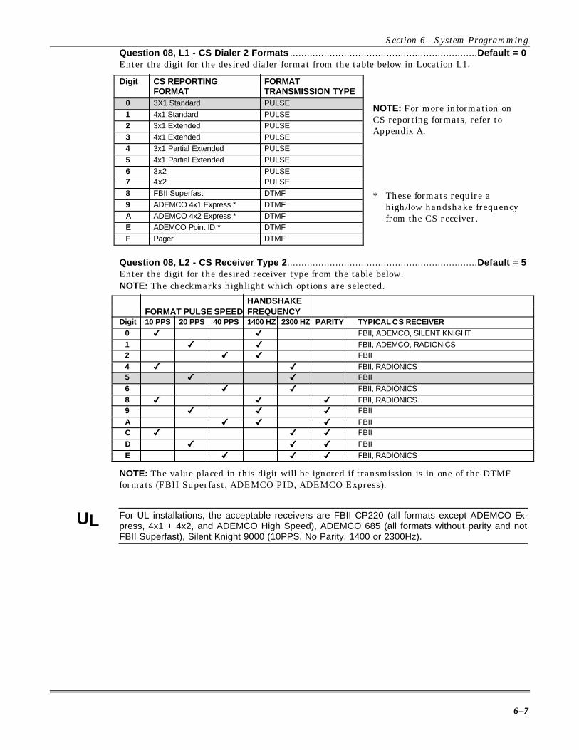
Section 6 - System Programming
6–7
Question 08, L1 - CS Dialer 2 Formats ..................................................................Default = 0Enter the digit for the desired dialer format from the table below in Location L1.
Digit CS REPORTING FORMATFORMAT TRANSMISSION TYPE
0 3X1 Standard PULSE 1 4x1 Standard PULSE 2 3x1 Extended PULSE 3 4x1 Extended PULSE 4 3x1 Partial Extended PULSE 5 4x1 Partial Extended PULSE 6 3x2 PULSE 7 4x2 PULSE 8 FBII Superfast DTMF 9 ADEMCO 4x1 Express * DTMF A ADEMCO 4x2 Express * DTMF E ADEMCO Point ID * DTMF F Pager DTMF
Question 08, L2 - CS Receiver Type 2...................................................................Default = 5Enter the digit for the desired receiver type from the table below.NOTE: The checkmarks highlight which options are selected.
HANDSHAKEFORMAT PULSE SPEED FREQUENCY
Digit 10 PPS 20 PPS 40 PPS 1400 HZ 2300 HZ PARITY TYPICAL CS RECEIVER
0 4 4 FBII, ADEMCO, SILENT KNIGHT1 4 4 FBII, ADEMCO, RADIONICS2 4 4 FBII4 4 4 FBII, RADIONICS5 4 4 FBII6 4 4 FBII, RADIONICS8 4 4 4 FBII, RADIONICS9 4 4 4 FBIIA 4 4 4 FBIIC 4 4 4 FBIID 4 4 4 FBIIE 4 4 4 FBII, RADIONICS
NOTE: The value placed in this digit will be ignored if transmission is in one of the DTMFformats (FBII Superfast, ADEMCO PID, ADEMCO Express).
UL For UL installations, the acceptable receivers are FBII CP220 (all formats except ADEMCO Ex-press, 4x1 + 4x2, and ADEMCO High Speed), ADEMCO 685 (all formats without parity and notFBII Superfast), Silent Knight 9000 (10PPS, No Parity, 1400 or 2300Hz).
* These formats require ahigh/low handshake frequencyfrom the CS receiver.
NOTE: For more information onCS reporting formats, refer toAppendix A.
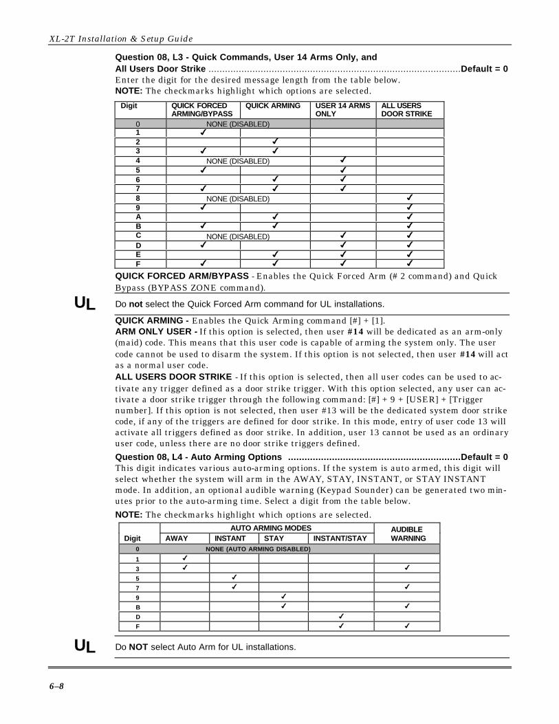
XL-2T Installation & Setup Guide
6–8
Question 08, L3 - Quick Commands, User 14 Arms Only, andAll Users Door Strike ............................................................................................Default = 0Enter the digit for the desired message length from the table below.NOTE: The checkmarks highlight which options are selected.
Digit QUICK FORCEDARMING/BYPASS
QUICK ARMING USER 14 ARMSONLY
ALL USERSDOOR STRIKE
0 NONE (DISABLED)1 4
2 4
3 4 4
4 NONE (DISABLED) 4
5 4 4
6 4 4
7 4 4 4
8 NONE (DISABLED) 4
9 4 4
A 4 4
B 4 4 4
C NONE (DISABLED) 4 4
D 4 4 4
E 4 4 4
F 4 4 4 4
QUICK FORCED ARM/BYPASS - Enables the Quick Forced Arm (# 2 command) and QuickBypass (BYPASS ZONE command).
UL Do not select the Quick Forced Arm command for UL installations.
QUICK ARMING - Enables the Quick Arming command [#] + [1].ARM ONLY USER - If this option is selected, then user #14 will be dedicated as an arm-only(maid) code. This means that this user code is capable of arming the system only. The usercode cannot be used to disarm the system. If this option is not selected, then user #14 will actas a normal user code.ALL USERS DOOR STRIKE - If this option is selected, then all user codes can be used to ac-tivate any trigger defined as a door strike trigger. With this option selected, any user can ac-tivate a door strike trigger through the following command: [#] + 9 + [USER] + [Triggernumber]. If this option is not selected, then user #13 will be the dedicated system door strikecode, if any of the triggers are defined for door strike. In this mode, entry of user code 13 willactivate all triggers defined as door strike. In addition, user 13 cannot be used as an ordinaryuser code, unless there are no door strike triggers defined.Question 08, L4 - Auto Arming Options ...............................................................Default = 0This digit indicates various auto-arming options. If the system is auto armed, this digit willselect whether the system will arm in the AWAY, STAY, INSTANT, or STAY INSTANTmode. In addition, an optional audible warning (Keypad Sounder) can be generated two min-utes prior to the auto-arming time. Select a digit from the table below.NOTE: The checkmarks highlight which options are selected.
AUTO ARMING MODESDigit AWAY INSTANT STAY INSTANT/STAY
AUDIBLE WARNING
0 NONE (AUTO ARMING DISABLED)
1 4
3 4 4
5 4
7 4 4
9 4
B 4 4
D 4
F 4 4
UL Do NOT select Auto Arm for UL installations.

Section 6 - System Programming
6–9
QUESTION 09MISCELLANEOUS OPTIONS ...................................................................... DEFAULT = 8010
Question 09, L1 & L2 - Group Bypass for Zones 1-7 andQuick Exit ...............................................................................L1 Default = 8, L2 Default = 0Select the zones to be bypassed as a single group from the tables below. If Quick Bypassing isenabled, group bypassing can be performed by the following sequence: [BYPASS] + [UserCode] + [#] or [BYPASS] + [#].NOTE: The checkmark indicates the zones to be bypassed as a group.
UL Quick Exit cannot be used in UL installations.
QUICK EXIT -If enabled, allows someone to leave a protected exit area while the system isarmed without causing an alarm, by first pressing the STAY key. Pressing the STAY keystarts a new exit delay during which the exit door may be opened and closed.
ZONE GROUP
Digit ZONE 5 ZONE 6 ZONE 7 QUICK EXIT
0 None None None None1 4
2 4
3 4 4
4 4
5 4 4
6 4 4
7 4 4 4
8 4
9 4 4
A 4 4
B 4 4 4
C 4 4
D 4 4 4
E 4 4 4
F 4 4 4 4
ZONE GROUPDigit ZONE 1 ZONE 2 ZONE 3 ZONE 4
0 None None None None1 4
2 4
3 4 4
4 4
5 4 4
6 4 4
7 4 4 4
8 4
9 4 4
A 4 4
B 4 4 4
C 4 4
D 4 4 4
E 4 4 4
F 4 4 4 4
Fire zones cannot be bypassed. Twenty-four-hour zones can be bypassed; however, they can-not be unbypassed if a violation exists on their zone terminals.
L1 L2

XL-2T Installation & Setup Guide
6–10
Question 09, L3 - No CS Bypass for Stay, Auto Stay Keyswitch,Armed Bypass Display ......................................................................................... Default = 1Select the desired options from the table below.NOTE: The checkmarks highlight which options are selected.
Digit NO CS BYPASSFOR STAY
AUTO STAYKEYSWITCH
ARMING BYPASSDISPLAY
BYPASS 3 ZONESONLY
0 1 4
2 4
3 4 4
4 4
5 4 4
6 4 4
7 4 4 4
8 4 9 4 4 A 4 4 B 4 4 4 C 4 4 D 4 4 4 E 4 4 4 F 4 4 4 4
NO CS BYPASS FOR STAY - This option specifies that bypasses will not be transmitted uponSTAY arming. If this option is not selected, then bypasses will be transmitted for each interiorzone that has been bypassed with the STAY arming.NOTE: Bypasses will be transmitted only if there is a bypass code defined (see Question 32,Location 1).AUTO-STAY KEYSWITCH - This option allows a keyswitch to utilize the AUTO-STAY feature.If it is enabled, then any keyswitch connected to the system (by selecting a zone type as key-switch, Questions 17-23, Location 1) will AUTO-STAY arm the system based on whether exitoccurs or not. If not enabled, keyswitch arming does not AUTO-STAY arm the system re-gardless of whether exit occurs or not.ARMED BYPASS DISPLAY - This option determines whether bypasses will be displayed onkeypads when the system is armed. To view, press the BYPASS button. If the option is notselected, then bypasses will not be displayed on the keypad after system arming.BYPASS 3 ZONES ONLY - This option allows the user to bypass up to 3 zones at once.Question 09, L4 - CS Dialer Attempts ................................................................... Default = 0This option selects the number of times the communicator will attempt to dial both CS receiv-ers. If CS #2 is not programmed, then this option determines the dialer attempts toCS #1. Select a digit from the table below.NOTE: This is valid for all CS receiver formats.
DIGIT NO. OF CS DIALER ATTEMPTS0 16 1 1 2 2 3 3 4 4 5 5 6 6 7 7 8 8 9 9 A 10 B 11 C 12 D 13 E 14 F 15
UL For UL installations, a valuebetween 5 and 10 dialer attemptsmust be selected.

Section 6 - System Programming
6–11
QUESTION 10BELL TIMEOUTS, CS TEST TIME, and MISCELLANEOUS ........................... DEFAULT = 5F26There are 4 Locations (L1-L4) within this question, as follows:
Question 10, L1 - Burglary Bell Timeout .............................................................. Default = 5
Question 10, L2 - Fire Bell Timeout ...................................................................... Default = FEnter the digit for the desired bell timeouts from the table below.
Digit BURGLARY & FIRE BELLTIMEOUTS
Digit BURGLARY & FIRE BELLTIMEOUTS
1 3 MINUTES A 30 MINUTES2 6 MINUTES B 33 MINUTES3 9 MINUTES C 36 MINUTES4 12 MINUTES D 39 MINUTES5 15 MINUTES E 42 MINUTES6 18 MINUTES F INFINITE7 21 MINUTES8 24 MINUTES9 27 MINUTES
UL BURGLARY BELL TIMEOUTS - For UL installations, the minimum bell cutoff is digit 5 (15 min-utes).
UL FIRE BELL TIMEOUTS - For UL installations, the minimum fire bell cutoff time is 4 minutes(digits 2 through F).
Question 10, L3 - CS Test Time Interval .............................................................. Default = 2This question determines the method of CS Test transmission, as follows:NOTE: The checkmarks highlight which options are selected.
CS TEST TIME INTERVALTEST BY TEST BY 1 24 27 60 90
Digit EVENT TIME HOUR HOUR WEEKLY DAYS DAYS DAYS0 4 4
1 4 4
2 4 4
3 4 4
4 4 4
5 4 4
6 4 4
7 4 4
8 4 4
9 4 4
A 4 4 4
B 4 4 4
C 4 4 4
D 4 4 4
E 4 4F 4 4
TEST INTERVAL - Select 1 hour, daily (24-hour), weekly (7 days), 27-day, 60-day, or 90-day.This interval is disabled by entering AA in CS code Q31.
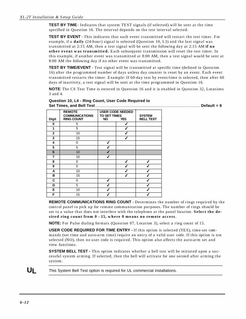
XL-2T Installation & Setup Guide
6–12
TEST BY TIME - Indicates that system TEST signals (if selected) will be sent at the timespecified in Question 16. The interval depends on the test interval selected.
TEST BY EVENT - This indicates that each event transmitted will restart the test timer. Forexample, if a daily (24-hour) signal is selected (Question 10, L3) and the last signal wastransmitted at 2:15 AM, then a test signal will be sent the following day at 2:15 AM if noother event was transmitted. Each subsequent transmission will reset the test timer. Inthis example, if another event was transmitted at 8:00 AM, then a test signal would be sent at8:00 AM the following day if no other event was transmitted.
TEST BY TIME/EVENT - Test signal will be transmitted at specific time (defined in Question16) after the programmed number of days unless day counter is reset by an event. Each eventtransmitted restarts the timer. Example: If 60-day test by event/time is selected, then after 60days of inactivity, a test signal will be sent at the time programmed in Question 16.
NOTE: The CS Test Time is entered in Question 16 and it is enabled in Question 32, Locations3 and 4.
Question 10, L4 - Ring Count, User Code Required toSet Times, and Bell Test ....................................................................................... Default = 6
REMOTE USER CODE NEEDEDCOMMUNICATIONS TO SET TIMES SYSTEM
Digit RING COUNT NO YES BELL TEST
0 0 4
1 5 4
2 10 4
3 15 4
4 0 4
5 5 4
6 10 4
7 15 4
8 0 4 4
9 5 4 4
A 10 4 4
B 15 4 4
C 0 4 4
D 5 4 4
E 10 4 4
F 15 4 4
REMOTE COMMUNICATIONS RING COUNT - Determines the number of rings required by thecontrol panel to pick up for remote communication purposes. The number of rings should beset to a value that does not interfere with the telephone at the panel location. Select the de-sired ring count from 0 - 15, where 0 means no remote access.
NOTE: For Pulse dialing formats (Question 07, Location 3), select a ring count of 15.
USER CODE REQUIRED FOR TIME ENTRY - If this option is selected (YES), time-set com-mands (set time and auto-arm time) require an entry of a valid user code. If this option is notselected (NO), then no user code is required. This option also affects the auto-arm set andview functions.
SYSTEM BELL TEST - This option indicates whether a bell test will be initiated upon a suc-cessful system arming. If selected, then the bell will activate for one second after arming thesystem.
UL This System Bell Test option is required for UL commercial installations.

Section 6 - System Programming
6–13
QUESTION 11ENTRY/EXIT TIMEOUTS & CROSS ZONE TIMEOUT ................................... DEFAULT = 6333There are 4 Locations (L1-L4) within this question that define the exit/entry times as follows:
Question 11, L1 - Exit Delay/Exit Delay Restart ..................................... Default = 6 (UL max)• Exit Delay: Enter the digit for desired entry/exit timeout provided in ENTRY/EXIT
TIMEOUTS table below.
UL For UL installations, one-minute delay is maximum entry/exit delay time permitted.
• Exit Delay Restart: Opening the entry/exit loop twice during exit timeout resets theexit timer and restarts the pulse sound. However, there may be times when the exittime is insufficient and/or the sounder must be silenced (if it's enabled, of course).During entry/exit time, pressing the STAY button will accomplish the following:
1. It will silence the sounder immediately.2. It will double the amount of entry/exit delay remaining based on the amount
of time remaining at the instant that the STAY button was pressed.Example: Assume entry/exit delay is programmed for 50 seconds and the end user is leavingthe premises. The pulse sounder turns on and user suddenly realizes he is disturbing otherpeople after 10 seconds of exit delay has elapsed. User presses the STAY button, which in-stantly silences the sounder and gives the user 80 seconds more of exit delay (40 seconds re-mained from initial exit delay, which is doubled at the moment STAY button is pressed).However, the amount of total delay time cannot exceed 255 seconds, irrespective of theamount of time remaining.
PULSE SOUNDS DURING ENTRY/EXIT TIMEOUTS
Programmed Timeout Sounder On/OffMore than 10 seconds 1/2 sec on, 1/2 sec off, 1/2 sec on, 6-1/2 sec off10 seconds or less 1/4 sec on, 1/4 sec off, 1/4 sec on, 1/4 sec off,
1/4 sec on, 1/4 sec off, 1/4 sec on, 2-3/4 sec off.
Question 11, L2 - Entry Delay #1 ......................................................................... Default = 3Enter the desired entry delay time. Refer to ENTRY/EXIT TIMEOUTS table below for validchoices.
UL The maximum entry delay time is 40 seconds for UL household applications.
Question 11, L3 - Entry Delay #2 ......................................................................... Default = 3Enter the desired entry delay time. Refer to ENTRY/EXIT TIMEOUTS table below for validchoices.
Digit ENTRY/EXITTIMEOUTS
Digit ENTRY/EXITTIMEOUTS
0 4 MINUTES, 30 SECONDS 8 1 MINUTE, 20 SECONDS1 10 SECONDS 9 1 MINUTE, 30 SECONDS2 20 SECONDS A 1 MINUTE, 40 SECONDS3 30 SECONDS B 1 MINUTE, 50 SECONDS4 40 SECONDS C 2 MINUTES5 50 SECONDS D 2 MINUTES, 10 SECONDS6 1 MINUTE E 2 MINUTES, 20 SECONDS7 1 MINUTE, 10 SECONDS F 2 MINUTES, 30 SECONDS
NOTE: Separate entry timeouts are selected for each zone in Questions 17-23, Location 2.
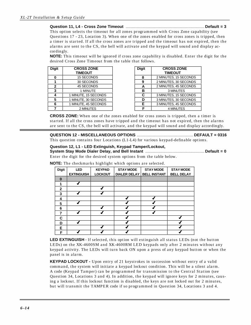
XL-2T Installation & Setup Guide
6–14
Question 11, L4 - Cross Zone Timeout ................................................................ Default = 3This option selects the timeout for all zones programmed with Cross Zone capability (seeQuestions 17 - 23, Location 3). When one of the zones enabled for cross zones is tripped, thena timer is started. If all the cross zones are tripped and the timeout has not expired, then thealarms are sent to the CS, the bell will activate and the keypad will sound and display ac-cordingly.NOTE: This timeout will be ignored if cross zone capability is disabled. Enter the digit for thedesired Cross Zone Timeout from the table that follows.
Digit CROSS ZONETIMEOUT
Digit CROSS ZONETIMEOUT
0 15 SECONDS 8 2 MINUTES, 15 SECONDS1 30 SECONDS 9 2 MINUTES, 30 SECONDS2 45 SECONDS A 2 MINUTES, 45 SECONDS3 1 MINUTE B 3 MINUTES4 1 MINUTE, 15 SECONDS C 3 MINUTES, 15 SECONDS5 1 MINUTE, 30 SECONDS D 3 MINUTES, 30 SECONDS6 1 MINUTE, 45 SECONDS E 3 MINUTES, 45 SECONDS7 2 MINUTES F 4 MINUTES
CROSS ZONE: When one of the zones enabled for cross zones is tripped, then a timer isstarted. If all the cross zones have tripped and the timeout has not expired, then the alarmsare sent to the CS, the bell will activate, and the keypad will sound and display accordingly.
QUESTION 12 - MISCELLANEOUS OPTIONS .............................................. DEFAULT = 0316This question contains four Locations (L1-L4) for various keypad-definable options.
Question 12, L1 - LED Extinguish, Keypad Tamper/Lockout,System Stay Mode Dialer Delay, and Bell Instant ................................................ Default = 0Enter the digit for the desired system options from the table below.
NOTE: The checkmarks highlight which options are selected.Digit LED
EXTINGUISHKEYPAD
LOCKOUTSTAY MODE
DIALER DELAYSTAY MODE
BELL INSTANTSTAY MODEBELL DELAY
01 44
2 44
3 44 44
4 44 44
5 44 44 44
6 44 44 44
7 44 44 44 44
C 44 44
D 44 44 44
E 44 44 44
F 44 44 44 44
LED EXTINGUISH - If selected, this option will extinguish all status LEDs (not the buttonLEDs) on the XK-4600SM and XK-4600RM LED keypads only after 2 minutes without anykeypad activity. The LEDs will turn back ON upon a press of any keypad button or when thepanel is in alarm.
KEYPAD LOCKOUT - Upon entry of 21 keystrokes in succession without entry of a validcommand, the system will initiate a keypad lockout condition. This will be a silent alarm.A code (Keypad Tamper) can be programmed for transmission to the Central Station (seeQuestion 34, Locations 3 and 4). In addition, the keypad will ignore keys for 2 minutes, caus-ing a lockout. If this lockout function is disabled, the keys are not locked out for 2 minutes,but will transmit the TAMPER code if so programmed in Question 34, Locations 3 and 4.
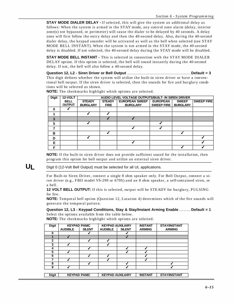
Section 6 - System Programming
6–15
STAY MODE DIALER DELAY - If selected, this will give the system an additional delay asfollows: When the system is armed in the STAY mode, any control zone alarm (delay, interiorzone(s) not bypassed, or perimeter) will cause the dialer to be delayed by 40 seconds. A delayzone will first follow the entry delay and then the 40-second delay. Also, during the 40-seconddialer delay, the keypad sounder will be activated as well as the bell when selected (see STAYMODE BELL INSTANT). When the system is not armed in the STAY mode, the 40-seconddelay is disabled. If not selected, the 40-second delay during the STAY mode will be disabled.
STAY MODE BELL INSTANT - This is selected in connection with the STAY MODE DIALERDELAY option. If this option is selected, the bell will sound instantly during the 40-seconddelay. If not, the bell will also follow a 40-second delay.
Question 12, L2 - Siren Driver or Bell Output ....................................................... Default = 3This digit defines whether the system will utilize the built-in siren driver or have a conven-tional bell output. If the siren driver is selected, then the sounds for fire and burglary condi-tions will be selected as shown.NOTE: The checkmarks highlight which options are selected.
AUDIO LEVEL VOLTAGE OUTPUTS/BUILT- IN SIREN DRIVERDigit 12-VOLTBELL
OUTPUTSTEADY
BURGLARYSTEADY
FIREEUROPEAN SWEEP
BURGLARYEUROPEANSWEEP FIRE
SWEEPBURGLARY
SWEEP FIRE
0 4
1 4 4
3 4 4
5 4 4
7 4 4
B 4 4
D 4 4
E 4 4
F 4 4
NOTE: If the built-in siren driver does not provide sufficient sound for the installation, thenprogram this option for bell output and utilize an external siren driver.
UL Digit 0 (12-Volt Bell Output) must be selected for all UL applications.
For Built-in Siren Driver, connect a single 8 ohm speaker only. For Bell Output, connect a si-ren driver (e.g., FBII model VS-299 or 679S) and an 8 ohm speaker, a self-contained siren, ora bell.12 VOLT BELL OUTPUT: If this is selected, output will be STEADY for burglary, PULSINGfor fire.NOTE: Temporal bell option (Question 12, Location 4) determines which of the fire sounds willgenerate the temporal pattern.
Question 12, L3 - Keypad Conditions, Stay & Stay/Instant Arming Enable .......... Default = 1Select the options available from the table below.NOTE: The checkmarks highlight which options are selected.
Digit KEYPAD PANIC KEYPAD AUXILIARY INSTANT STAY/INSTANTAUDIBLE SILENT AUDIBLE SILENT ARMING ARMING
0 4 41 4 42 4 4
3 4 44 4 4 45 4 4 46 4 4 4
7 4 4 48 4 4 49 4 4 4
Digit KEYPAD PANIC KEYPAD AUXILIARY INSTANT STAY/INSTANT
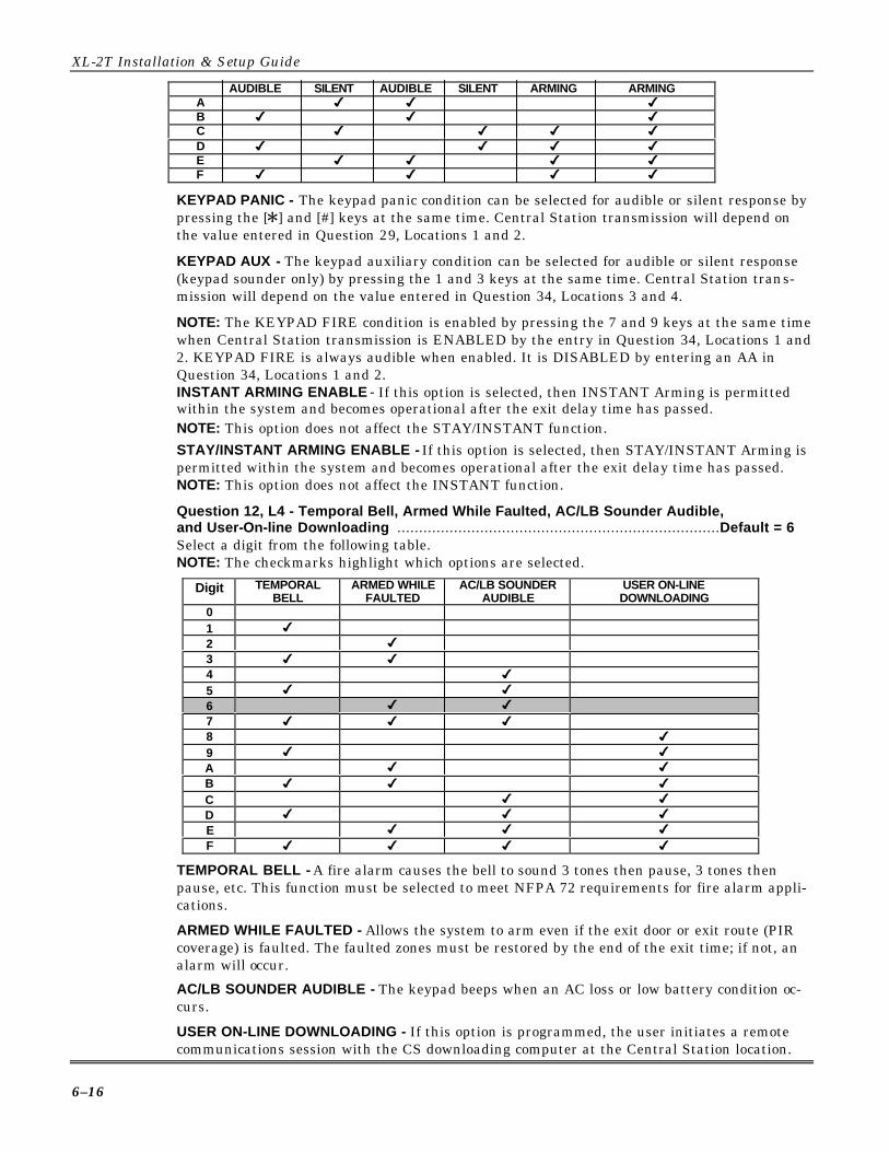
XL-2T Installation & Setup Guide
6–16
AUDIBLE SILENT AUDIBLE SILENT ARMING ARMINGA 4 4 4B 4 4 4C 4 4 4 4
D 4 4 4 4E 4 4 4 4F 4 4 4 4
KEYPAD PANIC - The keypad panic condition can be selected for audible or silent response bypressing the [Q] and [#] keys at the same time. Central Station transmission will depend onthe value entered in Question 29, Locations 1 and 2.
KEYPAD AUX - The keypad auxiliary condition can be selected for audible or silent response(keypad sounder only) by pressing the 1 and 3 keys at the same time. Central Station trans-mission will depend on the value entered in Question 34, Locations 3 and 4.
NOTE: The KEYPAD FIRE condition is enabled by pressing the 7 and 9 keys at the same timewhen Central Station transmission is ENABLED by the entry in Question 34, Locations 1 and2. KEYPAD FIRE is always audible when enabled. It is DISABLED by entering an AA inQuestion 34, Locations 1 and 2.INSTANT ARMING ENABLE - If this option is selected, then INSTANT Arming is permittedwithin the system and becomes operational after the exit delay time has passed.NOTE: This option does not affect the STAY/INSTANT function.STAY/INSTANT ARMING ENABLE - If this option is selected, then STAY/INSTANT Arming ispermitted within the system and becomes operational after the exit delay time has passed.NOTE: This option does not affect the INSTANT function.
Question 12, L4 - Temporal Bell, Armed While Faulted, AC/LB Sounder Audible,and User-On-line Downloading ..........................................................................Default = 6Select a digit from the following table.NOTE: The checkmarks highlight which options are selected.
Digit TEMPORALBELL
ARMED WHILEFAULTED
AC/LB SOUNDERAUDIBLE
USER ON-LINEDOWNLOADING
01 4
2 4
3 4 4
4 4
5 4 4
6 4 4
7 4 4 4
8 4
9 4 4
A 4 4
B 4 4 4
C 4 4
D 4 4 4
E 4 4 4
F 4 4 4 4
TEMPORAL BELL - A fire alarm causes the bell to sound 3 tones then pause, 3 tones thenpause, etc. This function must be selected to meet NFPA 72 requirements for fire alarm appli-cations.
ARMED WHILE FAULTED - Allows the system to arm even if the exit door or exit route (PIRcoverage) is faulted. The faulted zones must be restored by the end of the exit time; if not, analarm will occur.
AC/LB SOUNDER AUDIBLE - The keypad beeps when an AC loss or low battery condition oc-curs.
USER ON-LINE DOWNLOADING - If this option is programmed, the user initiates a remotecommunications session with the CS downloading computer at the Central Station location.

Section 6 - System Programming
6–17
On-line downloading allows the user to call the office and discuss the action required, and al-lows the CS operator to complete the request while on-line with no additional telephone callneeded. Pressing [#] + [CODE] enables this ON-LINE downloading option. Refer to USERON-LINE DOWNLOADING in Section 5: System Operation for the procedure.
USER UNATTENDED DOWNLOADING – If this option is programmed, the user can initiatean unattended download from the CS Downloading Computer by pressing [#] + [0] at the key-pad. Refer to USER ON-LINE DOWNLOADING in Section 5: System Operation for the pr o-cedure.
QUESTION 13SYSTEM OPTIONS....................................................................................... DEFAULT = 3000This question contains four Locations (L1-L4) for various keypad-definable options.Question 13, L1 - Dial Delay Doubled, Display Aborted, CS Test Sounder Ring Back,Dial Tone Detection ............................................................................................. Default = 3
Enter the digit for the desired system options from the table below.
NOTE: The checkmarks highlight which options are selected.
Digit DIAL DELAYDOUBLED
DISPLAYABORTED
CS TEST SOUNDERRING BACK
DIAL TONEDETECTION
0 Disabled Disabled Disabled Disabled 1 4 2 4 3 4 4 4 4 5 4 4 6 4 4 7 4 4 4 8 4 9 4 4 A 4 4 B 4 4 4 C 4 4 D 4 4 4 E 4 4 4 F 4 4 4 4
DIAL DELAY DOUBLED - If selected, will double the dial delay programmed in zones (Ques-tions 17−23, Location 4) from 15 seconds to 30 seconds.
DISPLAY ABORTED - Displays on a LCD keypad that the user has aborted an alarm. Anabort message occurs when a user cancels an alarm during dial delay. This option will onlyapply to zone(s) that are enabled for Dial Delay (Question 17-23, L4).
CS TEST SOUNDER RING BACK - Determines if the keypad will beep 4 times to acknowledgea successful CS test transmission to Central Station.DIAL TONE DETECTION - If enabled, panel waits four seconds. If no dial tone is detected, thepanel hangs up and moves to the next dialer attempt. It will continue in this fashion until alldialer attempts programmed are completed. If not enabled, the panel waits four seconds anddials, whether or not there is a dial tone.
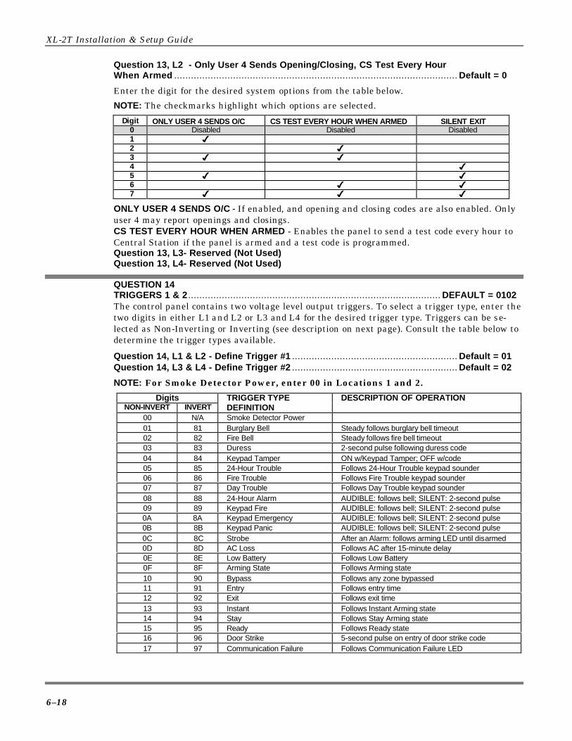
XL-2T Installation & Setup Guide
6–18
Question 13, L2 - Only User 4 Sends Opening/Closing, CS Test Every HourWhen Armed ..................................................................................................... Default = 0
Enter the digit for the desired system options from the table below.
NOTE: The checkmarks highlight which options are selected.
Digit ONLY USER 4 SENDS O/C CS TEST EVERY HOUR WHEN ARMED SILENT EXIT 0 Disabled Disabled Disabled 1 4 2 4 3 4 4 4 4 5 4 4 6 4 4 7 4 4 4
ONLY USER 4 SENDS O/C - If enabled, and opening and closing codes are also enabled. Onlyuser 4 may report openings and closings.CS TEST EVERY HOUR WHEN ARMED - Enables the panel to send a test code every hour toCentral Station if the panel is armed and a test code is programmed.Question 13, L3- Reserved (Not Used)Question 13, L4- Reserved (Not Used)
QUESTION 14TRIGGERS 1 & 2 .......................................................................................... DEFAULT = 0102The control panel contains two voltage level output triggers. To select a trigger type, enter thetwo digits in either L1 and L2 or L3 and L4 for the desired trigger type. Triggers can be se-lected as Non-Inverting or Inverting (see description on next page). Consult the table below todetermine the trigger types available.
Question 14, L1 & L2 - Define Trigger #1 ........................................................... Default = 01Question 14, L3 & L4 - Define Trigger #2 ........................................................... Default = 02
NOTE: For Smoke Detector Power, enter 00 in Locations 1 and 2.
Digits DESCRIPTION OF OPERATIONNON-INVERT INVERT
TRIGGER TYPEDEFINITION
00 N/A Smoke Detector Power01 81 Burglary Bell Steady follows burglary bell timeout02 82 Fire Bell Steady follows fire bell timeout03 83 Duress 2-second pulse following duress code04 84 Keypad Tamper ON w/Keypad Tamper; OFF w/code05 85 24-Hour Trouble Follows 24-Hour Trouble keypad sounder06 86 Fire Trouble Follows Fire Trouble keypad sounder07 87 Day Trouble Follows Day Trouble keypad sounder08 88 24-Hour Alarm AUDIBLE: follows bell; SILENT: 2-second pulse09 89 Keypad Fire AUDIBLE: follows bell; SILENT: 2-second pulse0A 8A Keypad Emergency AUDIBLE: follows bell; SILENT: 2-second pulse0B 8B Keypad Panic AUDIBLE: follows bell; SILENT: 2-second pulse0C 8C Strobe After an Alarm: follows arming LED until disarmed0D 8D AC Loss Follows AC after 15-minute delay0E 8E Low Battery Follows Low Battery0F 8F Arming State Follows Arming state10 90 Bypass Follows any zone bypassed11 91 Entry Follows entry time12 92 Exit Follows exit time13 93 Instant Follows Instant Arming state14 94 Stay Follows Stay Arming state15 95 Ready Follows Ready state16 96 Door Strike 5-second pulse on entry of door strike code17 97 Communication Failure Follows Communication Failure LED

Section 6 - System Programming
6–19
Digits DESCRIPTION OF OPERATIONNON-INVERT INVERT
TRIGGER TYPEDEFINITION
19 99 Keypad Sounder Follows keypad sounder1A 9A Ground Start Follows Dialing (Trigger #1 only)1B 9B Glassbreak Reset Resets Latched Glassbreak detectors1C 9C Exit Error Follows Exit Error1D 9D Auto Test Time Momentary pulse when CS Test is transmitted1E 9E Listen In Active after receiving a CS "kissoff" signal to enable
listening device1F 9F Line Seizure Panel seizes the phone line upon alarm and stays on
while panel is reporting to CS20 A0 Chime 2-second pulse when a zone is faulted21 A1 Alarm Restore Trigger ON when burg alarm sounds; OFF when all
burglary zones have sent CS restore22 A2 Fire/Latch Can turn on aux. devices upon fire alarm trigger ON
with fire bell, OFF with CS fire restore
NOTE: If Glassbreak Reset trigger type (1B/9B) is selected, then pressing [Q] on the key padwill activate the trigger. The trigger outputs are limited to approximately 50mA each.
NON-INVERT TRIGGER - The trigger output (positive to negative) is normally floating and ac-tively sinks (goes negative) on activation.
INVERT TRIGGER - The trigger output (positive to negative) is normally sinking (negativewith respect to positive) and floats on activation.
QUESTION 15AUTO ARMING TIME.................................................................................... DEFAULT = 1700If auto arming has been enabled, then enter the hour and minute in military time (24-hourclock) as follows:
Question 15, L1 & L2 - Hour of Day (00 - 24)........................................................Default = 17Enter the hour of the day in military time: 12 AM - 12 PM = (00 - 24).
NOTE: Quick Rule: 00 = Midnight; for times after 12 noon, add 12 hours to obtain the hour.Example: 1 AM would be entered as 01; 5 PM would be entered as 17.
Question 15, L3 & L4 - Minute within Hour (00 - 59) ............................................Default = 00
Example: To auto arm at 5:30 PM, enter 17 into L1 and L2, and 30 into L3 and L4.
NOTE: The auto arming time can also be programmed through the quick command [#] 5.
QUESTION 16CS TEST TIME ............................................................................................. DEFAULT = 0300If the control panel transmits a system TEST at a specific time of day, enter the hour and mi-nute in military time (24-hour clock) as follows:
Question 16, L1 & L2 - Hour of Day (00 - 24) .......................................................Default = 03Enter the hour of the day in military time: 12 AM - 12 PM (00 - 24).NOTE: Quick Rule: 00 = Midnight; for times after 12 noon, add 12 hours to obtain the hour.Example: 3 AM is entered as 03; 7 PM is entered as 19.
Question 16, L3 & L4 - Minute within Hour (00 - 59) ............................................Default = 00Example: To transmit at 5:30 PM, enter 17 into L1 and L2, and 30 into L3 and L4.
NOTE: The CS Test interval is selected in Question 10, Location 3 and is enabled in Question31, Locations 3 and 4.

XL-2T Installation & Setup Guide
6–20
QUESTIONS 17 – 23ZONE PROGRAMMINGQuestions 17 - 23 represent all the options related to programmable zones 1-7. There are fourLocations (L1-L4, starting on next page) in each question, which define various zone options.The zones are comprised of as many individual sensors as desired.
QUESTION 17ZONE 1 ........................................................................................................ DEFAULT = 2068Zone 1 = EOL Audible Delay Zone with Entry Timer #1, Bypass Enable, and Report Restore
QUESTION 18ZONE 2 ........................................................................................................ DEFAULT = 5068Zone 2 = EOL Audible Interior Follower Zone with Entry Timer #1, Bypass Enable, andReport Restore
QUESTION 19ZONE 3 ........................................................................................................ DEFAULT = 0068Zone 3 = EOL Audible Instant Zone with Entry Timer #1, Bypass Enable, and Report Restore
QUESTION 20ZONE 4 ........................................................................................................ DEFAULT = 0068Zone 4 = EOL Audible Instant Zone with Entry Timer #1, Bypass Enable, and Report Restore
QUESTION 21ZONE 5 ........................................................................................................ DEFAULT = 0068Zone 5 = EOL Audible Instant Zone with Entry Timer #1, Bypass Enable, and Report Restore
QUESTION 22ZONE 6 ........................................................................................................ DEFAULT = 0068Zone 6 = EOL Audible Instant Zone with Entry Timer #1, Bypass Enable, and Report Restore
QUESTION 23ZONE 7 ....................................................................................................... DEFAULT = A140Zone 7 = N/O Audible 24-Hour zone with Report Restore

Section 6 - System Programming
6–21
Questions 17 - 23, L1 - Zone Type DescriptionsLocation 1 defines the zone type for each zone. Enter the digit from the table below.NOTE: The checkmarks highlight which options are selected.
STAY ARMING OPTIONSDigitZONE TYPE AUTO STAY MANUAL STAY
0 Instant NONE2 Delay (Exit/Entry) NONE3 Delay (Exit/Entry) 4
4 Interior Follower 4
5 Interior Follower 4 4
6 Delay (Exit/Entry) 4
7 Delay (Exit/Entry) 4 4
8 Keyswitch NONE9 24-Hr. Trouble NONEA 24-Hr. Alarm NONEE Fire w/o verification NONEF Fire w/ verification NONE
Burglary (Controlled) ZonesDELAY (EXIT/ENTRY) - This is the industry standard exit/entry zone. When the system isarmed, exit time begins. After exit time expires, any subsequent violation of this zone will be-gin entry time. If the system is not disarmed within the programmed entry time, an alarmwill occur. The keypad sounder will annunciate steadily during entry time, unless there is analarm condition, at which time it will pulse. Delay zones will activate instantly, after exit timeexpires, when the system is armed in the INSTANT mode.
INTERIOR FOLLOWER - All interior zones have exit delay time upon system arming.All interior zones will have entry delay time if a delay zone is violated first. If this zone isviolated first, however, it will generate an immediate alarm. Interior zones will automaticallybe bypassed if the system is armed in the STAY mode.
INSTANT - This zone type (sometimes known as PERIMETER) will generate an alarm whenviolated while the system is armed.
UL AUTO STAY functions cannot be programmed for UL installations.
Stay Arming OptionsAUTO STAY - This zone type will automatically be bypassed if the system is armed in theAWAY mode and any delay zone has not been violated during exit delay time. The LCD key-pad will display an AUTO STAY indication. However, this zone is not bypassed if armed inSTAY mode.MANUAL STAY - This zone type will be bypassed when the system is armed in the STAYmode. It is not automatically bypassed if the system is armed in the AWAY mode and anydelay zone has not been violated during exit delay time.
AUTO & MANUAL STAY - This zone type will automatically be bypassed if the system isarmed in the AWAY mode and any delay zone has not been violated during the exit delaytime. The LCD keypad will display an AUTO STAY indication. Also, this zone is bypassed ifarmed in STAY mode.
EXIT ERROR WARNING - This option is always enabled for all delay or interior type zones. Atthe end of exit time, a 1-second window is started. If any delay or interior zones are violated afterarming within this window (exit time expires and entry delay time begins), the burglary bell andsounder will be turned on, forcing the user to enter their code to prevent a false alarm transmis-sion. This helps avoid the common false alarms that take place after arming the system. An exiterror message is transmitted after entry time expires. If the system is disarmed prior to the end ofentry time, no message will be transmitted to CS (Question 35, L1).

XL-2T Installation & Setup Guide
6–22
24-Hr. Zones
FIRE - Fire with Verification zones contain Fire Verification Logic. Upon detection of the firstviolation, smoke detector power on conventional 4-wire smoke detectors connected to ZONEmodules will be reset for a period of 8 seconds. After this time period, power is restored. For aperiod of 5 seconds, the fire zone will not be scanned, allowing the smoke detectors to settle.Future violations within a two-minute period will result in a PULSING BELL OUTPUT,RAPID PULSING ZONE LED, and IMMEDIATE transmission to the CS. Fire signals cannotbe aborted.
Entry of any valid user code will silence the sounder and bell. Entry of a valid user code for asecond time will reset smoke detector power and clear alarm memory. If the system detectsthat the fire zone is still violated within 2 minutes of power reset, the zone LED will pulseslowly to indicate a fire trouble. Thereafter, smoke detector power will be reset every 4 min-utes automatically in an attempt to clear the fire zone.
In the event the fire zone experiences an open, the system indicates fire trouble by pulsing thekeypad zone LED and sounder slowly. The system trouble code (followed by the zone code) isreported to the CS.Fire without Verification zones do not follow verification. They will trip instantaneously upona violation.
Fire zones will also cause a TROUBLE condition if the bell or speaker is disconnected.
Any valid user number silences the keypad. When a zone is selected for fire, it will go into atrouble condition whenever the bell or speaker is disconnected.24-HR. ALARM - This zone type is always active, independent of the system arming status.Programming options include audible (STEADY BELL) or silent (NO BELL or keypad indica-tions), with or without restore codes. Upon violation, the zone LEDs will pulse rapidly (audi-ble zones only) and an immediate CS transmission will occur that cannot be aborted.
24-Hour Alarm zones can be bypassed; however, they cannot be unbypassed if a violation ex-ists on the zone terminals.NOTE: 24-Hour zones should not be used for perimeter protection.
24-HR. TROUBLE - This zone type is always active, independent of the system arming status.Programming options include audible (PULSING KEYPAD SOUNDER) or silent, with orwithout restore codes. Upon violation, the zone LED will pulse slowly. TROUBLE conditionmust exist for 15 seconds before a transmission will occur. The keypad display and sounderwill clear upon zone restoral.
Fire zones cannot be bypassed. 24-HOUR TROUBLE must NOT be used for fire/burglaryprotection.
24-Hour Trouble zones can be bypassed; however, they cannot be unbypassed if a violationexists on the zone terminals. Any valid user code silences the keypad.
KEYSWITCH - Keyswitch zones toggle the arming status of the system. A keyswitch auto-matically arms the system in the STAY mode if the keyswitch is held for three seconds ormore; it arms in AWAY mode if held for 2 seconds or less.
Keyswitch zone operation has NOT been tested by Underwriters Laboratories.

Section 6 - System Programming
6–23
Question 17 - 23, L2 - Loop Type, Fast Zone, & Entry TimerL2 contains the loop EOL type and the entry delay timer to be used for the zone. Enter thedigit from the table below.NOTE: The checkmarks highlight which options are selected.
Digit EOL N/O N/C FAST ZONE ENTRYTIMER #1
ENTRYTIMER #2
INTERIOR ZONE w /oSTAY BYPASS
0 4 4
1 4 4
2 4 4
3* 4 4 4
4 4 4 4
5 4 4 4
6 4 4 4
7* 4 4 4 4
8 4 4
9 4 4
A 4 4
C 4 4 4
D 4 4 4
E 4 4 4
F* 4 4 4 4
* Digits 3, 7, and F apply to this table only if digit 4 is selected in Question 17, L1 (InteriorFollower). If Question 17, Location 1 is selected for any option except 4, then options 3, 7, andF above will not apply to this table.If a zone type 4 (Questions 17 - 23, Location 1) is selected, then entering a 3, 7 or F in L2 willstop that zone from reporting a BYPASS message when STAY armed. This BYPASS messagein STAY arm mode is dependent upon the selection of options in Question 09, L3 that enableARMING BYPASS DISPLAY reporting.LOOP TYPE - Choose between EOL supervision and N/O, N/C operation.FAST ZONE - If enabled, then the zone response will be 10mSec (connect alarm on Open-typedevices only). If not selected, it will be 280mSec.ENTRY TIMERS - Selects whether entry delay times 1 or 2 should be used for this zone. TheEntry/Exit delay times are defined within Question 11 of the programming sequence. Entrydelay time 1 should be selected for most zones. If the zone option delay or interior has beenselected, then either entry 1 or entry 2 can be selected. Entry timer applies only to entry/exit-type zones.INTERIOR ZONE w/o STAY BYPASS - When enabled (refer to paragraphs following the "*"above and also Question 17 - 23, L3 below), digits 3 and 7, EOL supervision and entry timer#1 become available. For digit F, EOL supervision, Fast zone reporting capability, and entrytimer #2 are made available.Question 17 - 23, L3 - Cross Zone, Bypass, & RestoreEnter the digit from the table below.NOTE: The checkmarks highlight which options are selected.
Digit CROSS ZONE BYPASS RESTORE
0 Disabled Disabled Disabled1 4
2 4
3 4 4
Digit CROSS ZONE BYPASS RESTORE
4 4
5 4 4
6 4 4
7 4 4 4
CROSS ZONE - When one of the zones enabled for cross zones is tripped, then a timer isstarted. If all the cross zones have tripped and the timeout has not expired, then the alarmsare sent to the CS, the bell will activate, and the keypad will sound and display accordingly.
UL CROSS ZONE programming cannot be used in UL installations.
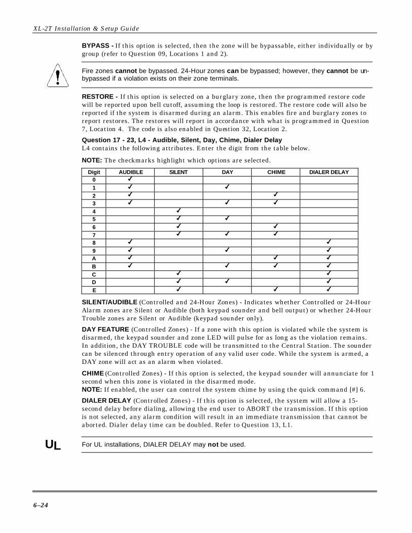
XL-2T Installation & Setup Guide
6–24
BYPASS - If this option is selected, then the zone will be bypassable, either individually or bygroup (refer to Question 09, Locations 1 and 2).
Fire zones cannot be bypassed. 24-Hour zones can be bypassed; however, they cannot be un-bypassed if a violation exists on their zone terminals.
RESTORE - If this option is selected on a burglary zone, then the programmed restore codewill be reported upon bell cutoff, assuming the loop is restored. The restore code will also bereported if the system is disarmed during an alarm. This enables fire and burglary zones toreport restores. The restores will report in accordance with what is programmed in Question7, Location 4. The code is also enabled in Question 32, Location 2.
Question 17 - 23, L4 - Audible, Silent, Day, Chime, Dialer DelayL4 contains the following attributes. Enter the digit from the table below.
NOTE: The checkmarks highlight which options are selected.
Digit AUDIBLE SILENT DAY CHIME DIALER DELAY0 4
1 4 4
2 4 4
3 4 4 4
4 4
5 4 4
6 4 4
7 4 4 4
8 4 4
9 4 4 4
A 4 4 4
B 4 4 4 4
C 4 4
D 4 4 4
E 4 4 4
SILENT/AUDIBLE (Controlled and 24-Hour Zones) - Indicates whether Controlled or 24-HourAlarm zones are Silent or Audible (both keypad sounder and bell output) or whether 24-HourTrouble zones are Silent or Audible (keypad sounder only).
DAY FEATURE (Controlled Zones) - If a zone with this option is violated while the system isdisarmed, the keypad sounder and zone LED will pulse for as long as the violation remains.In addition, the DAY TROUBLE code will be transmitted to the Central Station. The soundercan be silenced through entry operation of any valid user code. While the system is armed, aDAY zone will act as an alarm when violated.
CHIME (Controlled Zones) - If this option is selected, the keypad sounder will annunciate for 1second when this zone is violated in the disarmed mode.NOTE: If enabled, the user can control the system chime by using the quick command [#] 6.
DIALER DELAY (Controlled Zones) - If this option is selected, the system will allow a 15-second delay before dialing, allowing the end user to ABORT the transmission. If this optionis not selected, any alarm condition will result in an immediate transmission that cannot beaborted. Dialer delay time can be doubled. Refer to Question 13, L1.
UL For UL installations, DIALER DELAY may not be used.

Section 6 - System Programming
6–25
QUESTIONS 24 - 27ZONE CS CODESQuestions 24 - 27 define the programming codes to be transmitted to the Central Station foreach zone, and contain 4 locations, as follows:
QUESTION 24CS CODES for ZONES 1 & 2 ........................................................................ DEFAULT = 3132
Question 24, L1 & L2 - Zone 1 .............................................................................Default = 31
Question 24, L3 & L4 - Zone 2 .............................................................................Default = 32
QUESTION 25CS CODES for ZONES 3 & 4 ........................................................................ DEFAULT = 3334
Question 25, L1 & L2 - Zone 3 .............................................................................Default = 33
Question 25, L3 & L4 - Zone 4 .............................................................................Default = 34
QUESTION 26CS CODES for ZONES 5 & 6 ........................................................................ DEFAULT = 3536
Question 26, L1 & L2 - Zone 5 .............................................................................Default = 35
Question 26, L3 & L4 - Zone 6 .............................................................................Default = 36
QUESTION 27CS CODES for ZONES 7 & 8 .......................................................................DEFAULT = 27AA
Question 27, L1 & L2 - Zone 7 .............................................................................Default = 27
Question 27, L3 & L4 - Reserved (Not Used)
If a zone is selected as a Keyswitch zone type, and a two-digit reporting format is selected foropenings/closings, the second digit reported will be the second digit of the zone CS code. TOREPORT THE USER NUMBER CORRECTLY, THE FIRST DIGIT OF THE ZONE CS CODEMUST BE "0."
Zone Alarm CodesZones will transmit to the Central Station unless these digits are defined as AA for any indi-vidual zone. Based on the dialer format selected, enter the alarm code as follows:STANDARD FORMAT (3x1 or 4x1): Enter the desired single-digit alarm code in the first loca-tion for the specific zone. The value placed in the second digit will not be used.EXTENDED (3x1 Ext. or 4x1 Ext.): Enter the desired first digit of the alarm code into the firstdigit of the particular zone and the second digit into the second location.
PARTIAL EXTENDED (3x1 Part. Ext. or 4x1 Part. Ext.): Enter the desired digit in both Loca-tions for the zone. This will generate a single-digit transmission for alarms and troubles (thesecond digit will not be used) and extended transmissions for all system conditions such as re-stores, bypasses, openings/closings, etc. (the second digit will be used).3X2 OR 4X2: Enter the desired first digit of the alarm code into the first location and the sec-ond digit into the second location.FBI SUPERFAST: Enter the two-digit zone type into the two locations to be transmitted as thezone code.ADEMCO 4x1 EXPRESS: Enter the desired single-digit alarm code in the first location for thespecific zone. The value placed in the second digit will not be used.ADEMCO 4x2 EXPRESS: Enter the desired first digit of the alarm code into the first locationthe second digit into the second location.ADEMCO POINT ID (PID): The digit entered in the first location will select the PID event codeto be transmitted; refer to Appendix A for the PID event codes to be selected.NOTE: For more information on CS Reporting Formats, refer to Appendix A.

XL-2T Installation & Setup Guide
6–26
QUESTION 28CS CODES for AMBUSH and AC LOSS ......................................................DEFAULT = AAA1There are 4 locations (L1-L4) in this question, as follows:
Question 28, L1 & L2 - Ambush Code ............................................................... Default = AAIf an ambush code is defined, then user 15 is the ambush code. The rules regarding dialerformat apply here. If transmission is not desired, then program AA in locations L1 and L2.NOTE: AMBUSH transmissions are immediate and not abortable if programmed.
Question 28, L3 & L4 - AC Loss Code .............................................................. Default = A1The programming rules regarding dialer format apply here. AC LOSS will transmit a dedi-cated PID code of 301 if PID format is selected. If transmission is not desired, then programAA in locations L3 and L4.NOTE: AC LOSS is reported 15 minutes after detection when programmed.AC LOSS SOUNDER DISABLE: If the first digit (L3) of the AC Loss code is A, then to disablethe keypad sounder during AC loss, enter an A into the second digit (L4). The keypad displaywill still indicate AC loss.
QUESTION 29CS CODES for PANIC and LOW BATTERY .................................................DEFAULT = 22AAThere are 4 locations (L1-L4) in this question, as follows:
Question 29, L1 & L2 - Panic Code ................................................................... Default = 22The programming rules regarding dialer format apply here. If transmissions are not desired,then program AA in locations L1 and L2.NOTE: PANIC transmissions are immediate and not abortable when programmed.
Question 29, L3 & L4 - Low Battery Code ......................................................... Default = AAThe programming rules regarding dialer format apply here. If transmissions are not desired,then program AA in locations L3 and L4. Low battery transmissions will be reported 4 min-utes after detection. Low battery restore code will be reported within 4 minutes after detectionof good battery condition.
If transmission is in PID format, a dedicated PID code of 309 will be transmitted for low-batteryconditions.
QUESTION 30CS CODES for OPEN/CLOSE and WALK TEST......................................... DEFAULT = AAAAThere are 4 locations (L1-L4) in this question. Entry of AA into these locations means thatopenings and closings are not desired. If a dialer format other than standard is programmed,then the second digit transmitted will be the user number. If PID format is used, then a dedi-cated code of 402 will be transmitted.
Question 30, L1 - Opening Code........................................................................... Default = A
Question 30, L2 - Closing Code ........................................................................... Default = A
Question 30, L3 & L4 - Walk Test Code ................................................................ Default = ACodes are transmitted to the Central Station when a Walk Test is performed.
If a zone is selected as a Keyswitch zone type and a two-digit reporting format is selected, foropenings/closings the second digit reported will be the second digit of the zone CS code.To report the user number correctly, the first digit of the zone CS code must be "0."
QUESTION 31CS CODES for CANCEL and CS TEST...................................................... DEFAULT = BFAAThis question contains 4 locations for entering CS transmission codes, as follows:

Section 6 - System Programming
6–27
Question 31, L1 - Cancel Code ............................................................................ Default = BA cancel code can be transmitted to the Central Station if, after violation of a controlled zone,a user code is entered. If the zone is programmed for restore, then the restore code can betransmitted when the loop status has returned to normal, when bell timeout and loop arenormal, or when a code is entered. Entry of A in this field indicates that cancel codes are nottransmitted. In formats requiring two digits, the user number functions as the second digit.NOTE: The event code for PID transmission is 406.
Question 31, L2 - Reserved - NOT USEDQuestion 31, L3 & L4 - CS Test Code................................................................. Default = AAIn these locations, enter the desired Central Station code for transmission of the system TESTcode. The frequency and type of test is defined in Question 10, Location 3. Entry of AA indi-cates that the system TEST is not transmitted.NOTE: The event code for PID transmission is 602.
QUESTION 32CS CODES for BYPASS, RESTORE (FIRE & DAY TRBL.) .......................... DEFAULT = AEFAThere are 4 locations (L1-L4) in this question, as follows:Question 32, L1 - Bypass Code ............................................................................ Default = AThis is the single-digit system BYPASS CODE reported to the Central Station if a zone is by-passed upon arming. Entry of A means that bypasses are not transmitted. If a two-digit dial-ing format has been selected, then the Bypass code will be followed by the programmed seconddigit of the zone's code.
Question 32, L2 - Restore Code ........................................................................... Default = EThis is the single-digit system RESTORE CODE reported to the Central Station. Restores willbe reported for burglary or 24-hour zones that have been programmed with the restore option.Entry of A means that restores are not transmitted. If a two-digit dialer format has been pr o-grammed, then the restore code will be followed by the programmed second digit of the zonecode.
Question 32, L3 - Fire Trouble Code ..................................................................... Default = FThis is the single-digit system FIRE TROUBLE CODE reported to the Central Station. If atwo-digit format has been programmed, then this code will be followed by the second digit ofthe respective zone's code. Entry of A indicates that troubles are not transmitted. If PID for-mat is used, a dedicated event code of 373 will be transmitted.
Question 32, L4 - Day Trouble Code ..................................................................... Default = AThis is the single-digit system DAY TROUBLE CODE reported to the Central Station. If atwo-digit format has been programmed, then this code will be followed by the second digit ofthe respective zone's code. Entry of A indicates that troubles are not transmitted. If PID for-mat is used, a dedicated PID code of 156 will be transmitted.
If a zone is selected as a Fire Zone Type, the Fire Trouble CS Code (Question 32, Location 3)must be enabled along with the Restore CS Code (Question 32, Location 2).
QUESTION 33CS CODES for KEYPAD FIRE and KEYPAD AUXILIARY.............................. DEFAULT AAAAThere are 4 locations (L1-L4) in this question, as follows:
Question 33, L1 & L2 - Keypad Fire CS Code .................................................... Default = AAL1 and L2 enables the KEYPAD FIRE condition code, which will be transmitted upon activa-tion (by pressing the 7 and 9 keys on the keypad at the same time). This code can vary amongany of the zones pr ogrammed as fire.
NOTE: To disable the keypad fire condition and prevent CS reporting, enter AA. The keypadfire condition is always audible.Question 33, L3 & L4 - Keypad Auxiliary CS Code ............................................ Default = AA

XL-2T Installation & Setup Guide
6–28
L3 and L4 is the code transmitted to the CS for KEYPAD AUXILIARY condition (by pressing1 and 3 on the keypad). To disable the keypad auxiliary CS reporting, enter AA.
NOTE: The keypad auxiliary condition can be silent or audible (keypad sounder only) based onthe Question 13, Location 1.
QUESTION 34CS CODES for DOWNLOAD and KEYPAD TAMPER................................. DEFAULT = AAAAThis question contains 4 locations: L1 and L2 contain the download code, while L3 and L4contain the CS keypad tamper code.
Question 34, L1 & L2 - Download Code ............................................................ Default = AAThis code will be reported whenever the panel has been downloaded. Enter AA to disable.
Question 34, L3 & L4 - Keypad Tamper Code ................................................... Default = AAIf 21 digits are entered through the keypad without entry of a valid user code, then the panelwill transmit a silent alarm to the Central Station. If a keypad tamper report code is entered,it will be transmitted to the Central Station. If a two-digit CS transmission code is selected(for example, 4x2 or Extended), then both digits will be transmitted. To disable CS transmis-sion of keypad tamper, enter AA.
QUESTION 35CS CODES for RECENT CLOSE, EXIT ERROR,and SWINGER SHUTDOWN ...................................................................... DEFAULT = 546AThis question contains 4 locations for entering CS transmission codes, as follows:
Question 35, L1 - Exit Error Code ........................................................................ Default = 5An exit fault condition exists if a violation of a zone occurs after system arming but before ex-piration of the exit time. If this code is activated, then the exit fault code is transmitted in ad-dition to the corresponding zone alarm condition. To disable the exit error transmission code,enter A into Location 1.
NOTE: For Point ID transmissions, an event code of 457 is transmitted.
Question 35, L2 - Recent Close Code .................................................................. Default = 4This code is transmitted if an alarm condition occurs within 5 minutes of system closing. En-try of A into this location will prevent transmission of this condition.
NOTE: The event code for PID transmission is 459.
Question 35, L3 - Swinger Shutdown Code ......................................................... Default = 6This code is for CS transmission if swinger shutdown has occurred. Swinger shutdown is pr o-grammed in Question 7, Location 4. Entry of A into this location will prevent transmission ofthis condition.
Question 35, L4 - Reserved - NOT USED

Section 6 - System Programming
6–29
Zone Descriptor ProgrammingThe LCD keypads have the capability to display 12-character zone descriptors that can beprogrammed directly through the keypad. The zone descriptors appear on the first portion ofthe second line of LCD display. They are entered as Questions 36 - 42.NOTE: These descriptors can be accessed only by an LCD keypad or PC downloader software.Program zone descriptors in the following questions:
QUESTION 36ZONE 1 DESCRIPTOR..............................................................................DEFAULT = ZONE 1
QUESTION 37ZONE 2 DESCRIPTOR..............................................................................DEFAULT = ZONE 2
QUESTION 38ZONE 3 DESCRIPTOR..............................................................................DEFAULT = ZONE 3
QUESTION 39ZONE 4 DESCRIPTOR..............................................................................DEFAULT = ZONE 4
QUESTION 40ZONE 5 DESCRIPTOR..............................................................................DEFAULT = ZONE 5
QUESTION 41ZONE 6 DESCRIPTOR..............................................................................DEFAULT = ZONE 6
QUESTION 42ZONE 7 DESCRIPTOR..............................................................................DEFAULT = ZONE 7
Example: To program the descriptor for zone 3, enter Q38 to access Question 38.
When programming the English zone descriptors, use the following keystrokes:
KEYSTROKE ACTION
[0] Inserts a SPACE and advances the cursor.[CODE] Moves the cursor to the LEFT one space.
[INSTANT] Moves the cursor to the RIGHT one space.[7] INCREMENTS the character one at a time at the cursor.
[QQ ] [7] Scrolls forward (UP) through the character set.NOTE: Pressing any key will stop the scroll.
[9] DECREMENTS the character one at a time at the cursor.[#] [9] Scrolls backward (DOWN) through the character set.
NOTE: Pressing any key will stop the scroll
NOTE: The characters available through the LCD-based keypads are as follows:
[¥]̂ _�!"#$%&'()*+,-./0123456789:;<=>?@ABCDEFGHIJKLMNOPQRSTUVWXYZ

XL-2T Installation & Setup Guide
6–30

7–1
S E C T I O N 7
Data Entry via Keypads• • • • • • • • • • • • • • • • • • • • • • • • • • • • • • • • • • • • • • • • • • • • • • • • •
GeneralThis section describes the keystrokes used to perform keypad programming. It also explainshow to interpret the data displayed on LED keypads (XK-406, XK-508, XK-4600RM, XK-4600SM, 6615) and LCD keypads (XK-5LC, XK-7LC) during programming operations.NOTE: Actual keypad programming should be performed only after completion of the pr o-gramming sheet.
How to Enter Programming Mode via Either LED or LCD KeypadsThe SYSTEM programming mode can be entered while DISARMED ONLY, as follows:TO ENTER INSTALLER PROGRAMMING: press [CODE] + [QQ ] + [INSTALLER] + [1]
where:[CODE] CODE button[QQ ] Star (Q) button[INSTALLER] 4-digit installer code (default = 2468)[1] "1" button. This places you in Installer Mode 1.
What You See on the LED KeypadsPROGRAM MODE = READY LED:Upon entering the installer keypad programming mode, the READY LED will slowly pulse,and will continue to pulse until leaving this mode. The remaining LEDs display the questionnumber and location contents as follows:
NOTE: The LED key-pads DO NOT dis-play the current loca-tion (position withinthe question). Youmust keep track ofthe location withinthe question or elsestart from the begin-ning and move to thedesired position usingthe [#] button. How-ever, the LCD key-pads display the cur-rent location (see nextpage).

XL-2T Installation & Setup Guide
7–2
QUESTION NUMBERS = ZONE 1-6 LEDs:There are 36 total questions, with multiple data entry locations. Zone 1 through 6 LEDs dis-play the current question number only. The question number is the total you get when youADD the values of all zone LEDs that are ON. Refer to the previous pageEXAMPLES: Zone 1 ON, Zones 2-6 OFF....................................................QUESTION 01
Zone 1 ON, Zone 2 ON, Zones 3-6 OFF..................................QUESTION 03Zone 1 OFF, Zones 2-5 ON, and Zone 6 OFF .........................QUESTION 30
LOCATION DATA CONTENTS = ARM, STAY, INST, AC/LB LEDs:All questions have 4 locations except for questions 01, 02, and 03, which have 16 locations.These four LEDs display the data that resides in each location within the current question,not the location itself. Referring to the table that follows and the above explanation, the bi-nary value associated with each LED must be added to calculate the total data for each loca-tion.EXAMPLES: ARM LED ON, STAY, INST, and AC/LB LEDs OFF .................DATA = 1
ARM LED ON, STAY LED ON, others OFF ..........................DATA = 3
The following table displays binary values that you will see on these LEDs for the lettersA-F, which may be entered in some locations on the program sheet.To enter the characters A - F, press the [CODE] key and the number 1 for an A; [CODE]plus 2 for B; [CODE] plus 3 for C; etc.
LETTER NUMERICALVALUE
RESULTING LED STATUS
A 10 ARM OFF, STAY ON, INST OFF, AC/LB ONB 11 ARM and STAY ON, Zone 11 OFF, AC/LB ONC 12 ARM and STAY OFF, INST and AC/LB OND 13 ARM ON, STAY OFF, INST and AC/LB ONE 14 ARM OFF, STAY, INST, and AC/LB ONF 15 All four LEDs ON
What You See on the LCD KeypadUpon entering the installer keypad programming mode, the following will be displayed onthe LCD keypads:
QUES: 01 L: 01DATA = 1
The display shows the current question number (QUES:), the location within the question(L:), and the current value within that location (DATA=). This corresponds to the program-ming worksheet.
How to Enter DataThis section of the manual describes the keystrokes used to enter the data written on theprogram sheet.
MOVEMENT BETWEEN QUESTIONSSystem program mode starts with Question 01 displayed. Random jumps to any question canbe made by pressing the [Q ] (star) button and the 2-digit question number.Questions can be accessed randomly or sequentially.Example: To go to Question 07, press Q07.The question number is displayed by zone 1-6 LEDs. The other LEDs display the contents ofthe first location in that question.

Section 7 - Data Entry via Keypads
7–3
MOVEMENT WITHIN QUESTIONSZone 1-6 LEDs display the question number and ARM, STAY, INST, and AC/LB LEDs dis-play the contents (data) within each location. Movement from location L1 to the next loc a-tion within any question can be performed by pressing the [#] button.
ARM, STAY, INST, and AC/LB LEDs will display the data in each location as the [#] buttonis pressed. To revert to the data located in L1, press Q06; if you’re in this first location andwant to edit the data in L4, press the [#] button three times in succession.
DATA ENTRYTo alter the value in any location, enter the desired digit from the program sheet and pressthe [#] button.
The [#] button must be pressed after the entry of the desired digit. The system will not programthe digit until the [#] button is pressed, so that if a mistake is made it can be changed.
Numeric values of 0-9 can be entered by pressing the respective keypad button.Press the CODE button followed by 1-6 for values A-F, as follows:
VALUE KEYSTROKES VALUE KEYSTROKESA [CODE] + [1] D [CODE] + [4]B [CODE] + [2] E [CODE] + [5]C [CODE] + [3] F [CODE] + [6]
Example: To enter an A, press [CODE] button followed by [1] button.
EXIT SYSTEM PROGRAM MODEAfter all programming has been completed, press the STAY button to exit the system pr o-gram mode. All the LEDs will turn ON for approximately three seconds, then the system willreturn to normal daily operation.
QUESTION ACKNOWLEDGMENTThe keypad will beep between keystrokes. In addition, a beep will be generated confirmingadvancement between question numbers.Five beeps will be generated if an invalid input is entered. In that case, you remain at thequestion number and location just prior to the input error.
SUMMARY OF SYSTEM PROGRAMMING
To Enter Programming: [CODE] + [QQ ] + [4-digit Installer Code]
To Skip a Question: [QQ ] + [2-digit Question Number]
To Move Within a Question: Press the [#] button until the desired location is reached
To Enter Data: [single digit: 0-9, A-F] + [#]
Hexadecimal Entries:
A = [CODE] + [1] D = [CODE] + [4]B = [CODE] + [2] E = [CODE] + [5]C = [CODE] + [3] F = [CODE] + [6]
To Exit Programming: [STAY] button

XL-2T Installation & Setup Guide
7–4

8–1
S E C T I O N 8
System Defaults• • • • • • • • • • • • • • • • • • • • • • • • • • • • • • • • • • • • • • • • • • • • • • • • •
The control panel is preprogrammed from the factory with default values. These values havebeen selected to meet the requirements of a common installation, and may suit your needs.
FACTORY DEFAULT VALUES: To reload, remove all power from the system (AC and DC).Next, short JP1 and JP2; with short still intact, reapply power (AC, then DC) and wait 8seconds. Then remove short with power still applied. The installer can also do a system oruser code default through Installer Mode 1 (refer to "Installer Modes" in Section 9: Sum-mary of Keypad Functions).
NOTE: A programming option known as DEFAULT LOCKOUT exists within theEZMATE/COMPASS PC Downloader devices. If this option is selected, then a system defaultwill not overwrite the CSID or installer code portion of the program. This will prevent an in-staller other than the original installer from taking over an account without cooperation.
QUESTION DEFAULT VALUE00 Installer Code 246801 Primary Telephone Number 234AAAAAAAAAAAAA02 Secondary Telephone Number AAAAAAAAAAAAAAAA03 Callback Number AAAAAAAAAAAAAAAA04 PBX Prefix AAAA05 Account Number 1 123406 Account Number 2 AAAA07 CS Dialer 1 & System Options 051408 CS Dialer 2 & System Options 050009 Miscellaneous Options 801010 Bell Timeouts, CS Test Time, & Misc. 5F2611 Entry/Exit & Cross Zone Timeouts 633312 Miscellaneous Options 031613 System Options 300014 Triggers 1 & 2 010215 Auto Arm Time 170016 CS Test Time 030017 Zone 1 Type 206818 Zone 2 Type 506819 Zone 3 Type 006820 Zone 4 Type 006821 Zone 5 Type 006822 Zone 6 Type 006823 Zone 7 Type A14024 CS Codes for Zones 1 & 2 313225 CS Codes for Zones 3 & 4 333426 CS Codes for Zones 5 & 6 353627 CS Code for Zones 7 27AA28 CS Codes for Ambush & AC Loss AAA129 CS Codes for Panic & Low Battery 22AA30 CS Codes for Open/Close AAAA31 CS Codes for Cancel & CS Test BAAA
QUESTION DEFAULT VALUE32 CS Codes for Bypass, Restore,
Day Trouble, & Fire TroubleAEFA
33 CS Codes for Keypad Fire & Key-pad Auxiliary
AAAA
34 CS Codes for Download & KeypadTamper
AAAA
35 CS Codes for Recent Close, ExitError, & Swinger Shutdown
546A
USER NUMBER DEFAULT CODE APPLICATION
01 1234 Master User02 NULL Master User03 NULL Normal User04 NULL Normal User05 NULL Normal User06 NULL Normal User07 NULL Normal User08 NULL Normal User09 NULL Normal User10 NULL Normal User11 NULL Normal User12 NULL Normal User13 NULL Normal User14 NULL Normal User15 NULL Normal User
QUESTION DEFAULT VALUE36 ZONE 1 DESCRIPTOR ZONE 1 (LCD Keypads ONLY)37 ZONE 2 DESCRIPTOR ZONE 2 (LCD Keypads ONLY)38 ZONE 3 DESCRIPTOR ZONE 3 (LCD Keypads ONLY)39 ZONE 4 DESCRIPTOR ZONE 4 (LCD Keypads ONLY)40 ZONE 5 DESCRIPTOR ZONE 5 (LCD Keypads ONLY)41 ZONE 6 DESCRIPTOR ZONE 6 (LCD Keypads ONLY)42 ZONE 7 DESCRIPTOR ZONE 7 (LCD Keypads ONLY)

XL-2T Installation & Setup Guide
8–2

9–1
S E C T I O N 9
Summary of Keypad Functions• • • • • • • • • • • • • • • • • • • • • • • • • • • • • • • • • • • • • • • • • • • • • • • • •
User FunctionsARMING/DISARMING: [4-digit user code]STAY ARMING: [STAY] [4-digit user code]INSTANT ARMING: [INSTANT] [4-digit user code]STAY/ INSTANT ARMING: [STAY] [INSTANT] [4-digit user code]BYPASS: [BYPASS] [4-digit user code] [Zone number]QUICK BYPASS: [BYPASS] [Zone number]GROUP BYPASS: [BYPASS] [4-digit user code] [#]QUICK GROUP BYPASS: [BYPASS] [#]USER CODE PROGRAMMING: [CODE] [Master user code] [user #] [4-digit user code]USER CODE DELETION: [CODE] [Master user code] [user #] [Q ]QUICK ARM: [#] [1]QUICK FORCED ARM: [#] [2]SET TIME: [#] [3] [4-digit user code] [Hour] [Minute] [Day] [Year]DISPLAY ZONE DIR.: [#] [4] (LCD Keypads only)SET AUTO ARM TIME: [#] [5] [4-digit user code] [Hour] [Minute]DISPLAY/TOGGLE TIME: [#] [6]DISPLAY TIME: [#] [7] (LCD Keypads only)DISPLAY AUTO ARM TIME: [#] [8] (LCD Keypads only)DOOR STRIKE: [#] [9] [code] [Trigger number]USER ON-LINE DOWNLOAD: [#] [CODE]PANIC: [#] and [Q ] at the same timeFIRE: [7] and [9] at the same timeAUXILIARY: [1] and [3] at the same time
AMBUSH: [user code 15]
Installer ModesKEYPAD PROGRAMMING: [CODE] [Q] [installer code] [1]SYSTEM DEFAULT: [CODE] [Q] [installer code] [1] then press [1] and [3] at the
same timeUSER CODE DEFAULT: [CODE] [Q] [installer code] [1] then press [7] and [9] at the
same timeWALK TEST: [CODE] [Q] [installer code] [2]WALK TEST w/ BELL [CODE] [Q] [installer code] [3]SYSTEM LOG VIEW: [CODE] [Q] [installer code] [4]SYSTEM DEFAULT: [CODE] [Q] [installer code] [7]UNATTENDED DOWNLOAD: [CODE] [Q] [installer code] [8]
OR[#] [0]
ON-LINE DOWNLOAD: [CODE] [Q] [installer code] [9]

XL-2T Installation & Setup Guide
9–2

A–1
A P P E N D I X A
Central Station Reporting Formats• • • • • • • • • • • • • • • • • • • • • • • • • • • • • • • • • • • • • • • • • • • • • • • • •
This security system is designed to transmit data to a Central Station receiver when analarm, system trouble, or an opening/closing occurs. Due to the many different types of CSreceivers in the market, this system can transmit data in various formats. Each installingcompany determines which format best suits its needs based on many factors. Of these, theCS receiver type is a major factor.In transmitting data to the CS receiver, the first event that occurs is that the system's digitalcommunicator will seize the home phone lines. Then, it will dial the CS#1 telephone number(Programming Question 01). When the CS receiver picks up the ringing phone line, it willtransmit a "handshake" frequency (1400 Hz, 2300 Hz, or HiLo) back to the digital communi-cator. After receiving the "handshake" frequency, the digital communicator will transmit thedata in the format programmed in Question 04, Locations 1, 2, and 3 (either in pulse orDTMF). Assuming the CS receiver verifies the data transmission as valid (after 2 successfulrounds of data or 1 valid parity round), it will transmit a "kissoff" frequency back to the digi-tal communicator. This causes the communicator to stop transmitting, unless more data isavailable, in which case additional data transmissions and kissoffs will occur. After the finalkissoff, the CS receiver will release the phone line and process the data to its display and as-sociated peripherals (computer and printer). If for any reason the digital communicator doesnot receive the kissoff, it will proceed to dial the CS#2 telephone number or dial again theCS#1 telephone number (if CS#2 is not used). It will continue to dial (8 times for each CStelephone number programmed) until a kissoff is received. If, after dialing 8 times for eachCS telephone number programmed, a kissoff is not received, the system will display "CommFail" (communication failure) at the keypad. This message is cleared after the next success-ful transmission or by the user at the keypad.The following is a general description of the various formats transmitted by this system.
Standard (3x1 or 4x1)The Standard Reporting Format is AAA E or AAAA E, where:
AAAA = Three- or four-digit account number (Program Questions 5 and 6)E = Single-digit event code; it is the first of the 2 programmable reporting code digits
Standard format is transmitted in pulse and involves a 3- or 4-digit account number followedby a single-digit event code. It can be transmitted with parity (1 round of data) or withoutparity (2 rounds of data). A disadvantage of this format is that it can only transmit a total of15 event codes (0 - 9, B - F) without identifying zones or users. Examples:
3x1 w/o PARITY 3x1 w/ PARITY123 3 (1st round) 123 3 6 (single round)123 3 (2nd round) 123 3 (resulting data)123 3 (resulting data)4x1 w/o PARITY 4x1 w/ PARITY1234 3 (1st round) 1234 3 2 (single round)1234 3 (2nd round) 1234 3 (resulting data)1234 3 (resulting data)
Parity is a number derived automatically by the dialer utilizing a mathematical formula (modulo15). Example: 123 3 adds up to 9. This number is subtracted from the next highest number that isa multiple of 15; in this example, that is 15; 15 - 9 = 6. If the CS receiver accepts an even paritydigit, it considers the data transmission valid, delivers a kissoff and processes the data. The par-ity digit is not displayed. Its only purpose is for validation of data transmitted. It is not a program-mable digit; it is generated automatically by the dialer when the parity option is selected in pro-gramming Question 04, Location 2. The obvious advantage of using parity is speed. The trans-mission time between dialer and receiver is shorter because fewer digits are transmitted with itthan without it.

XL-2T Installation & Setup Guide
A–2
Extended (3x1 Ext. or 4x1 Ext.)The Extended Reporting Format is AAA EZ or AAAA EZ, where:
AAAA = Three- or four-digit account number (Program Questions 08 and 09)E = Single-digit event code; it is the first of the 2 programmable reporting code digitsZ = Zone or user identifier; it is the second of the 2 programmable reporting code digits
Extended format is transmitted in pulse and involves a 3- or 4-digit account number followedby a double-digit reporting code. The only purpose for the Extended format (sometimesknown as Universal or Expanded format) is to be able to transmit more than 15 codes to theCS receiver. It does this by extending the event code from the previous round of data, re-sulting in a 2-digit reporting code. It can be transmitted with parity (2 rounds of data) orwithout parity (4 rounds of data). There are 15 possible event codes, each of which can have15 different zone or user identifiers. As a result, a total of 225 individual events can be re-ported. Examples:
3x1 Ext. w/o PARITY 3x1 Ext. w/ PARITY123 3 (1st round) 123 3 (2nd round) 123 3 6 (1st round)333 1 (3rd round) 333 1 (4th round) 333 1 5 (2nd round)123 31 (resulting data) Burglary Zone 1 123 31 (r esulting data) Burglary Zone 14x1 Ext. w/o PARITY 4x1 Ext. w/ PARITY1234 3 (1st round) 1234 3 (2nd round) 1234 3 2 (1st round)3333 1 (3rd round) 3333 1 (4th round) 3333 1 2 (2nd round)1234 31 (resulting data) Burglary Zone 1 1234 31 (resulting data) Burglary Zone 1
Partial Extended (3x1 Part. Ext. or 4x1 Part. Ext.)The Partial Extended Reporting Format is AAA EZ or AAAA EZ, where:
AAAA = Three- or four-digit account number (Program Questions 08 and 09)E = Single-digit event code; it is the first of the 2 programmable reporting code digitsZ = Zone or user identifier; it is the second of the 2 programmable reporting code digits
The Partial Extended format is a combination of both the Standard and Extended formats.It transmits in pulse a standard message for alarm conditions and an extended message forrestores and other system conditions. To report a standard message, enter a numerical digit(0 - 9) for the first of the 2-digit reporting code; for an extended message, enter a hexadecimaldigit (B - F) for the first of the 2-digit reporting code. The extended messages are used when-ever a zone or user identification is needed (bypasses, restores, openings/closings, etc.). It canalso transmit with and without parity. Examples:
3x1 Stand. w/o PARITY (Alarm) 3x1 Part. Ext. w/o PARITY (Restore)123 3 (1st round) 123 E (1st round) 123 E (2nd round)123 3 (2nd round) EEE 1 (3rd round) EEE 1 (4th round)123 3 (resulting data) Burglary 123 E1 (resulting data) Burglary
3x2 or 4x2The 3x2 or 4x2 Reporting Format is AAA EZ or AAAA EZ, where:
AAAA = Three- or four-digit account number (Program Questions 08 and 09)E = Single-digit event code; it is the first of the 2 programmable reporting code digitsZ = Zone or user identifier; it is the second of the 2 programmable reporting code digits
This format is also in pulse and is an alternative to the Extended format; it also transmits a2-digit reporting code. Its specific meaning is a 3- or 4-digit account number followed by a 2-digit alarm code. It can be transmitted with parity (1 round of data) or without parity (2rounds of data).

Appendix A
A–3
There are 15 possible event codes, each of which can have 15 different zone identifiers. As aresult, a total of 225 individual events can be reported. It is different from the Extended for-mat in the way it transmits. This is illustrated in the examples below:
3x2 w/o PARITY 3x2 w/ PARITY123 31 (1st round) 123 31 5 (1st round)123 31 (2nd round) 123 31 (resulting data) Burglary Zone 1123 31 (resulting data) Burglary Zone 14x2 w/o PARITY 4x2 w/ PARITY1234 31 (1st round) 1234 31 1 (1st round)1234 31 (2nd round) 1234 31 (resulting data) Burglary Zone 11234 31 (resulting data) Burglary Zone 1
FBII Superfast (4x3x1)The FBII Superfast Reporting Format is AAAA AZZ S, where:
AAAA = Four-digit account number (Program Questions 05 and 06)A = Alarm type; it is the first of the 2 programmable reporting code digitsZZ = Zone or user identifier; it is the second of the 2 programmable reporting code digitsS = Signal type; it is the first of the 2 programmable reporting code digits
This format is commonly known as 4x3x1. A total of 9 digits (including the parity digit) aresent in DTMF. It enables reporting of 256 (00 - FF) unique zone or user identifiers instead ofthe 15 possible identifiers of most other pulse formats. In addition, it transmits at a muchgreater speed than the conventional pulse formats, since it uses DTMF (touch-tones) insteadof pulses to transmit the data, and it always sends a parity digit.On alarms, openings, and closings, the alarm type digit will be the same as the signal type.This will indicate the type of activity or condition that has occurred. However, on bypasses,restores, and troubles, the alarm type will not be the same as the signal type. Instead, thesignal type will change indicating the current condition of the zone. This is a unique featureof this format that allows more intelligent reporting of the activity occurring in the system.For instance, the following unique messages can be transmitted:
1234 1 01 1 Fire Zone 0011234 1 01 E Restore Fire Zone 0011234 1 01 F Trouble Fire Zone 001
ADEMCO 4x1 ExpressThe 4x1 Express Reporting Format is AAAA E, where:
AAAA =Three- or four-digit account number (Program Questions 05 and 06)E = Single-digit event code; it is the first of the 2 programmable reporting code digits
This format transmits in DTMF a total of 6 digits (including the parity digit). It is similar tothe Standard format in that it can transmit only 15 reporting codes. However, its advantageis speed because it transmits touch-tones instead of pulses, and it always sends a paritydigit. Examples:
123 3 6 (1st round)123 3 (resulting data) Burglary
ADEMCO 4x2 ExpressThe 4x2 Express Reporting Format is AAAA EZ, where:
AAAA =Three- or four-digit account number (Program Questions 05 and 06)E = Single-digit event code; it is the first of the 2 programmable reporting code digitsZ = Zone or user identifier; it is the second of the 2 programmable reporting code digits
This format transmits in DTMF a total of 7 digits (including the parity digit). This format issimilar to the Extended and 4x2 formats in that it can transmit a total of 225 individual re-porting events. However, its advantage is speed because it transmits touch-tones instead ofpulses, and it always sends a parity digit. Examples:
1234 31 1 (1st round)1234 31 (resulting data) Burglary Zone 1

XL-2T Installation & Setup Guide
A–4
ADEMCO Point IDThe Point ID Reporting Format is AAA 18 QXYZ GG ZZZ, where:
AAAA = Four-digit account number (Program Questions 05 and 06)18 = Uniquely identifies this format to the receiver and to an automation system,
but is not displayed or printed.Q = Event qualifier, which gives specific event information:
1 = New Event or Opening3 = New Restore or Closing
XYZ = Event code: The event code is a 3-digit code (3 decimal digits). For zone alarmsand some conditions, this can be specified; other conditions are dedicated; seethe tables below.
GG = Group number; this panel will report 01.ZZZ = Zone, sensor, or user identifier (3 decimal digits). For user-initiated actions such
as openings/closings, this will be the actual user number (01 - 15).
This format is also known as ADEMCO Contact ID. A total of 16 digits (including the paritydigit) are sent in DTMF. It enables reporting of 999 (001 - 999) unique zone or user identifi-ers instead of the 15 possible identifiers of most other pulse formats. This feature allows thefull reporting capability of this system (7 zones and 15 users). In addition, it transmits at amuch greater speed than the conventional pulse formats, since it uses DTMF (touch-tones)instead of pulses to transmit the data, and it always sends a parity digit. Its main advantageover all the other formats is its large number of event codes (see tables below) with the abil-ity to pinpoint an event (alarm, trouble, bypass, restore, etc.) to a specific zone (up to 7 zonesin this system) and to report openings/closings for many users (up to 15 users in this system).
For some reporting codes, the first of the two programmable digits determines the PID eventcode to be transmitted, while other reporting codes transmit a dedicated PID event code re-gardless of the digit programmed in the first location. In both cases, if transmissions are notdesired, then program AA in Locations 1 and 2. Refer to the following tables to select the PIDevent codes to be transmitted.
BURGLARY ZONE TYPES FIRE ZONE TYPES
Digit EVENTCODE
ENGLISH OUTPUT ATCS RECEIVER
Digit EVENTCODE
ENGLISH OUTPUT ATCS RECEIVER
0 122 Silent Panic 0 110 Fire Alarm1 123 Audible Panic 1 111 Smoke2 130 Burglary 2 112 Combustion3 131 Perimeter 3 113 Water Flow4 132 Interior 4 114 Heat5 133 24-Hour Alarm 5 115 Pull Station6 134 Entry/Exit 6 116 Duct7 135 Day/Night 7 117 Flame8 136 Outdoor 8 140 General Alarm9 137 Tamper 9 150 24-Hour Non-BurgA 140 General Alarm A 158 High TemperatureB 144 Sensor Tamper B 159 Low TemperatureC 155 Foil Break C 200 Fire SupervisoryD 156 Day Trouble D 201 Low H2O Pressure
E 202 Low CO2
F 203 Gate Valve Sensor

Appendix A
A–5
24-HOUR ALARM TYPES 24-HOUR TROUBLE TYPESDigit EVENT
CODEENGLISH OUTPUT AT
CS RECEIVERDigit EVENT
CODEENGLISH OUTPUT AT
CS RECEIVER
0 100 Medical 0 100 Medical1 101 Pendant Transmitter 1 122 Silent Panic2 120 Panic Alarm 2 123 Audible Panic3 122 Silent Panic 3 137 Tamper4 123 Audible Panic 4 150 24-Hour Non-Burg5 130 Burglary 5 153 Loss of Heat6 133 24-Hour Alarm 6 155 Foil Break7 135 Day/Night 7 156 Day Trouble8 137 Tamper 8 158 High Temperature9 140 General Alarm 9 159 Low TemperatureA 150 24-Hour Non-Burg A 300 System TroubleB 151 Gas Detected B 301 AC LossC 152 Refrigeration C 302 Low System BatteryD 153 Loss of Heat D 310 Ground FaultE 154 Water Leakage E 373 Fire TroubleF 155 Foil Break F 380 Sensor Trouble
KEYPAD ZONES (Fire*, Panic*, Aux.*, Ambush) BYPASS TYPES
Digit EVENTCODE
ENGLISH OUTPUT ATCS RECEIVER
Digit EVENTCODE
ENGLISH OUTPUT ATCS RECEIVER
0 100 Medical 0 570 Zone Bypassed1 101 Pendant Transmitter 1 571 Fire Zone Bypassed2 110 Fire Alarm 2 572 24-Hr Zone Bypassed3 111 Smoke 3 573 Burg. Zone Bypassed4 112 Combustion 4 574 Group Bypass5 117 Flame6 120 Panic Alarm7 121 Duress (Ambush)8 122 Silent Panic9 123 Audible PanicA 130 BurglaryB 133 24-Hour AlarmC 140 General AlarmD 150 24-Hour Non-Burg
E 115 Fire Pull Station
DEDICATED CODES DEDICATED CODESEVENTCODE
ENGLISH OUTPUT ATCS RECEIVER
EVENTCODE
ENGLISH OUTPUT ATCS RECEIVER
137 Keypad Tamper 407 Remote Arm156 Day Trouble 408 Quick Arm301* AC Loss 409 Keyswitch Zone309* Battery Test Fail 457 Exit Error373 Fire Trouble 459 Recent Close401 O/C by User 575 Swinger Bypass403 Auto Arm 602* Test - Periodic406 Cancel on Open 412* Download Code
* NOTE: These codes have no zone/user code associated with them; they will report 000 forthese digits.

XL-2T Installation & Setup Guide
A–6

B–1
A P P E N D I X B
Troubleshooting• • • • • • • • • • • • • • • • • • • • • • • • • • • • • • • • • • • • • • • • • • • • • • • • •
SYMPTOM POSSIBLE CAUSE REMEDY
1. LED or LCD: Keypaddisplay not lit
1a. AC & DC power out
1b. Keypad not powered
1a. Check transformer & batteryconnection; check AC input & batt.volt. (w/ transformer disconnected).
1b. Check term. 15(+) & 12(-) for 12VDC.
2. LED KP: AC/LB light OFFLCD KP: AC LOSS
2a. Primary AC power out
2b. Faulty keypad
2a. Check transformer connection; checkAC input voltage.
2b. Replace keypad.
3. LED KP: AC/LB lightslowly blinking
LCD KP: LOW BAT
3a. DC power out
3b. Low battery voltage
3a. Check battery connections; check battery voltage (w/ transformer disconnected).
3b. Same as 3A except volt. <11VDC.Let battery charge; replace battery.
4. LED KP: ARM light slowly blinkingLCD KP: COMMFAILURE
4a. Failure to communicate w/ Central Station
4b. Faulty panel/dialer4c. Faulty telephone lines
4a. Telephone lines cut or disconnected; repair or replace wiring as required.CS information misprogrammed.
4b. Replace panel.4c. Consult local telephone company.
5. LED KP: ZONE light ON & READY light OFFLCD KP: NOT READY:ZN # & SYSTEM NOT READY
5a. Zone faulted; system notready
5b. Faulty keypad
5c. Faulty panel
5a. Check loop wiring for open/short & repair: check EOL res istor for open orwrong value.
5b. Replace keypad.
5c. Check zone terminal voltage for 3.3VDC; bypass zone temporarily; replace panel.
6. Siren/speaker does notsound
6a. Faulty siren/speaker
6b. Faulty wiring
6c. Faulty panel/bell output
6a. Connect 12VDC to siren/speaker; if no sound is produced, replace siren/ speaker.
6b. Check wiring for an open or short circuit and replace wiring if necessary.
6c. Check terminals 22 (+) & 23 (-) for 12VDC when panel is in alarm (if programmed for bell output). If no voltage is measured, replace panel.
For more complicated problems, consult our Technical Support at (1-800) 645-7492.

XL-2T Installation & Setup Guide
B–2

C–1
A P P E N D I X C
System Planning Worksheet• • • • • • • • • • • • • • • • • • • • • • • • • • • • • • • • • • • • • • • • • • • • • • • • •
ZONE ZONESOPTIONS 1 2 3 4 5 6 7
LOOP TYPE(Check 1 only) G EOL G EOL G EOL G EOL G EOL G EOL G EOL
G N/O G N/O G N/O G N/O G N/O G N/O G N/O
G N/C G N/C G N/C G N/C G N/C G N/C G N/C
ZONE TYPE G Instant G Instant G Instant G Instant G Instant G Instant G Instant
(Check 1 only) G Delay G Delay G Delay G Delay G Delay G Delay G Delay
G Interior G Interior G Interior G Interior G Interior G Interior G InteriorG 24-Hour Alarm G 24-Hour Alarm G 24-Hour Alarm G 24-Hour Alarm G 24-Hour Alarm G 24-Hour Alarm G 24-Hour Alarm
G 24-Hour Trble G 24-Hour Trbl G 24-Hour Trbl G 24-Hour Trbl G 24-Hour Trbl G 24-Hour Trbl G 24-Hour Trbl
G Fire G Fire G Fire G Fire G Fire G Fire G Fire
G Keyswitch G Keyswitch G Keyswitch G Keyswitch G Keyswitch G Keyswitch G Keyswitch
SENSOR G Contacts G Contacts G Contacts G Contacts G Contacts G Contacts G Contacts
(Check 1 only) G PIR G PIR G PIR G PIR G PIR G PIR G PIR
G Glassbreak G Glassbreak G Glassbreak G Glassbreak G Glassbreak G Glassbreak G Glassbreak
G Smoke Det. G Smoke Det. G Smoke Det. G Smoke Det. G Smoke Det. G Smoke Det. G Smoke Det.G Push Button G Push Button G Push Button G Push Button G Push Button G Push Button G Push Button
G Vibration Sen. G Vibration Sen. G Vibration Sen. G Vibration Sen. G Vibration Sen. G Vibration Sen. G Vibration Sen.
G Other _______ G Other _______ G Other _______ G Other _______ G Other _______ G Other _______ G Other _______
FAST LOOP G YES G YES G YES G YES G YES G YES G YES
RESPONSE G NO G NO G NO G NO G NO G NO G NO
ENTRY TIMER G Entry Dly #1 G Entry Dly #1 G Entry Dly #1 G Entry Dly #1 G Entry Dly #1 G Entry Dly #1 G Entry Dly #1
(Check 1 only) G Entry Dly #2 G Entry Dly #2 G Entry Dly #2 G Entry Dly #2 G Entry Dly #2 G Entry Dly #2 G Entry Dly #2
CROSS ZONE G YES G YES G YES G YES G YES G YES G YES
G NO G NO G NO G NO G NO G NO G NO
DESCRIPTOR GGGG GGGG GGGG GGGG GGGG GGGG GGGG(12 CHARACTERS) GGGG GGGG GGGG GGGG GGGG GGGG GGGG
GGGG GGGG GGGG GGGG GGGG GGGG GGGG
USERNUMBER
SPECIAL USERAPPLICATION
USER ASSIGNEDTO
(PERSON'S NAME)01 Master User02 Master User03 Normal04 Normal05 Normal06 Normal07 Normal08 Normal09 Normal10 Normal11 Normal12 Normal13 Normal14 Arm Only: G Yes G No15 Ambush/Duress:
G Yes G No
KEYPADTYPES
KEYPAD(S)TOTAL (4 max.)
INSTALLEDLOCATION
XK-5LCXK-7LC
XK-406XK-508
XK-4600SMXK-4600RM
6615

XL-2T Installation & Setup Guide
C–2

D–1
A P P E N D I X DSystem Programming Worksheet
• • • • • • • • • • • • • • • • • • • • • • • • • • • • • • • • • • • • • • • • • • • • • • • • •00-INSTALLER CODE DEFAULT = 2468
L1 L2 L3 L4
01 PRIMARY TELEPHONE NUMBER DEFAULT = 234AAAAAAAAAAAAA
L1 L2 L3 L4 L5 L6 L7 L8 L9 L10 L11 L12 L13 L14 L15 L16
02 SECONDARY TELEPHONE NUMBER DEFAULT = AAAAAAAAAAAAAAAA
L1 L2 L3 L4 L5 L6 L7 L8 L9 L10 L11 L12 L13 L14 L15 L16
03 CALLBACK TELEPHONE NUMBER DEFAULT = AAAAAAAAAAAAAAAA
L1 L2 L3 L4 L5 L6 L7 L8 L9 L10 L11 L12 L13 L14 L15 L16
04 TELEPHONE PREFIX DEFAULT = AAAA
L1 L2 L3 L4
05 ACCOUNT NUMBER 1 DEFAULT = 1234L1 L2 L3 L4
06 ACCOUNT NUMBER 2 DEFAULT = AAAA
L1 L2 L3 L4
07 DIALER 1 & SYSTEM OPTIONS DEFAULT = 0514
L1 L2 L3 L4
08 DIALER 2 & SYSTEM OPTIONS DEFAULT = 0500L1 L2 L3 L4
09 MISCELLANEOUS OPTIONS DEFAULT = 8010
L1 L2 L3 L4
10 BELL TIMEOUTS, CS TEST TIME DEFAULT = 5F26
L1 L2 L3 L4
11 ENTRY/EXIT & CROSS TIMEOUTS DEFAULT = 6333L1 L2 L3 L4
12 MISCELLANEOUS OPTIONS DEFAULT = 0316
L1 L2 L3 L4
13 SYSTEM OPTIONS DEFAULT = 3000
L1 L2 L3 L4
14 TRIGGERS 1 & 2 DEFAULT = 0102L1 L2 L3 L4
15 AUTO ARM TIME DEFAULT = 1700
L1 L2 L3 L4
16 CS TEST TIME DEFAULT = 0300
L1 L2 L3 L4
17 ZONE 1 TYPE DEFAULT = 2068L1 L2 L3 L4
18 ZONE 2 TYPE DEFAULT = 5068
L1 L2 L3 L4
19 ZONE 3 TYPE DEFAULT = 0068L1 L2 L3 L4
20 ZONE 4 TYPE DEFAULT = 0068
L1 L2 L3 L4
21 ZONE 5 TYPE DEFAULT = 0068
L1 L2 L3 L4
22 ZONE 6 TYPE DEFAULT = 0068
L1 L2 L3 L4
23 ZONE 7 TYPE DEFAULT = A140L1 L2 L3 L4
24 ZONES 1 & 2 CS CODE DEFAULT = 3132
L1 L2 L3 L4
25 ZONES 3 & 4 CS CODE DEFAULT = 3334
L1 L2 L3 L4
26 ZONES 5 & 6 CS CODE DEFAULT = 3536L1 L2 L3 L4
27 ZONE 7 CS CODE DEFAULT = 27AA
L1 L2 L3 L4
28 AMBUSH & AC LOSS DEFAULT = AAA1
L1 L2 L3 L4
29 PANIC & LOW BATTERY DEFAULT = 22AAL1 L2 L3 L4
30 OPEN/CLOSE/WALK TEST DEFAULT = AAAA
L1 L2 L3 L4
31 CANCEL & CS TEST DEFAULT = BAAA
L1 L2 L3 L4
32 BYPASS, RESTORE (FIRE & DAY TRBL) DEFAULT = AEFAL1 L2 L3 L4
33 KEYPAD FIRE & AUXILIARY DEFAULT = AAAA
L1 L2 L3 L4
34 DOWNLOAD & KEYPAD TAMPER DEFAULT = AAAA
L1 L2 L3 L4
35 RECENT CLOSE, EXIT, & SWINGER DEFAULT = 546AL1 L2 L3 L4
TO ENTER PROGRAMMING MODE: [CODE] [QQ ] [4-digit Installer Code] [1]TO SKIP A QUESTION: [QQ ] [2-digit Question Number]TO MOVE WITHIN A QUESTION: Press the [#] key until desired locationTO ENTER DATA: [single digit: 0 - 9, A - F] [#]
HEXADECIMAL ENTRIES:A = [CODE] [1] D = [CODE] [4]B = [CODE] [2] E = [CODE] [5]C = [CODE] [3] F = [CODE] [6]
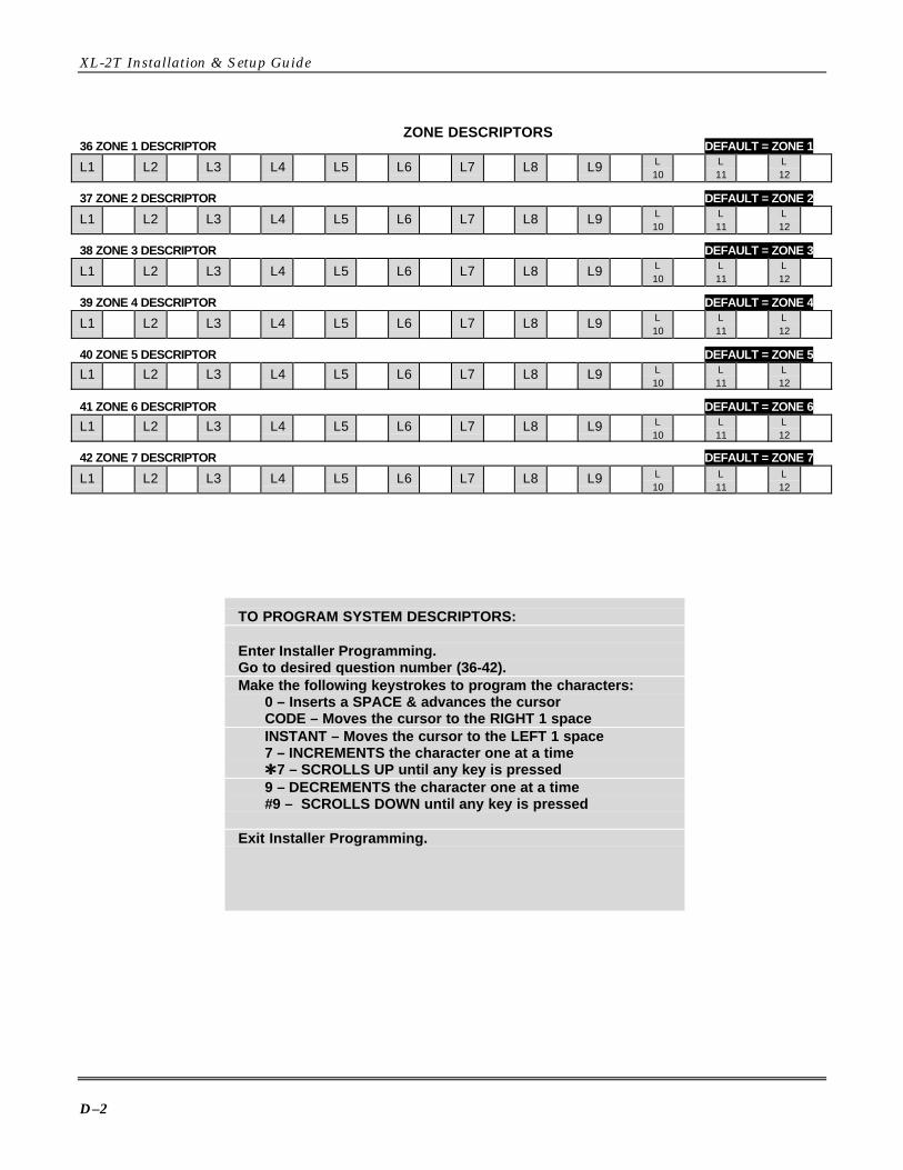
XL-2T Installation & Setup Guide
D–2
ZONE DESCRIPTORS36 ZONE 1 DESCRIPTOR DEFAULT = ZONE 1
L1 L2 L3 L4 L5 L6 L7 L8 L9 L10
L11
L12
37 ZONE 2 DESCRIPTOR DEFAULT = ZONE 2
L1 L2 L3 L4 L5 L6 L7 L8 L9 L10
L11
L12
38 ZONE 3 DESCRIPTOR DEFAULT = ZONE 3
L1 L2 L3 L4 L5 L6 L7 L8 L9 L10
L11
L12
39 ZONE 4 DESCRIPTOR DEFAULT = ZONE 4
L1 L2 L3 L4 L5 L6 L7 L8 L9 L10
L11
L12
40 ZONE 5 DESCRIPTOR DEFAULT = ZONE 5
L1 L2 L3 L4 L5 L6 L7 L8 L9 L10
L11
L12
41 ZONE 6 DESCRIPTOR DEFAULT = ZONE 6
L1 L2 L3 L4 L5 L6 L7 L8 L9 L10
L11
L12
42 ZONE 7 DESCRIPTOR DEFAULT = ZONE 7
L1 L2 L3 L4 L5 L6 L7 L8 L9 L10
L11
L12
TO PROGRAM SYSTEM DESCRIPTORS:
Enter Installer Programming.Go to desired question number (36-42).Make the following keystrokes to program the characters:
0 – Inserts a SPACE & advances the cursorCODE – Moves the cursor to the RIGHT 1 spaceINSTANT – Moves the cursor to the LEFT 1 space7 – INCREMENTS the character one at a timeQQ7 – SCROLLS UP until any key is pressed9 – DECREMENTS the character one at a time#9 – SCROLLS DOWN until any key is pressed
Exit Installer Programming.

E–1
A P P E N D I X E
Warnings and Limitations• • • • • • • • • • • • • • • • • • • • • • • • • • • • • • • • • • • • • • • • • • • • • • • • •While this system is an advanced design security system, it does not offer guaranteed protection against burglary, fire, or otheremergency. Any alarm system, whether commercial or residential, is subject to compromise or failure to warn for a variety ofreasons.For example:
• Intruders may gain access through unprotected openings or have the technical sophistication to bypass an alarmsensor or disconnect an alarm warning device.
• Intrusion detectors (e.g., passive infrared detectors), smoke detectors, and many other sensing devices will notwork without power. Battery operated devices will not work without batteries, with dead batteries or if the batter-ies are not put in properly. Devices powered solely by AC will not work if their AC power supply is cut off for anyreason, however briefly.
• Signals sent by wireless transmitters may be blocked or reflected by metal before they reach the alarm receiver.Even if the signal path has been recently checked during a weekly test, blockage can occur if a metal object ismoved into the path.
• A user may not be able to reach a panic or emergency button quickly enough.• While smoke detectors have played a key role in reducing residential fire deaths in the United States, they may
not activate or provide early warning for a variety of reasons in as many as 35% of all fires, according to datapublished by the Federal Emergency Management Agency. Some of the reasons smoke detectors used in con-junction with this System may not work are as follows: Smoke detectors may have been improperly installed andpositioned. Smoke detectors may not sense fires that start where smoke cannot reach the detectors, such as inchimneys, in walls, or roofs, or on the other side of closed doors. Smoke detectors may not sense a fire on an-other level of a residence or building. A second-floor detector, for example, may not sense a first-floor or base-ment fire. Moreover, smoke detectors have sensing limitations. No smoke detector can sense every kind of fireevery time. In general, detectors may not always warn about fires caused by carelessness and safety hazardslike smoking in bed, violent explosions, escaping gas, improper storage of flammable materials, overloadedelectrical circuits, children playing with matches, or arson. Depending on the nature of the fire and/or the locationof the smoke detectors, the detector, even if it operates as anticipated, may not provide sufficient warning to al-low all occupants to escape in time to prevent injury or death.
• Passive Infrared Motion Detectors can detect intrusion only within the designed ranges as diagrammed in theirinstallation manual. Passive Infrared Detectors do not provide volumetric area protection. They do create multiplebeams of protection, and intrusion can be detected only in unobstructed areas covered by the beams. They can-not detect motion or intrusion that takes place behind walls, ceilings, floors, closed doors, glass partitions, glassdoors, or windows. Mechanical tampering, masking, painting, or spraying of any material on the mirrors, win-dows, or any part of the optical system can reduce their detection ability. Passive Infrared Detectors sensechanges in temperature; however, as the ambient temperature of the protected area approaches the temperaturerange of 90 to 150F, the detection performance can decrease.
• Alarm warning devices such as sirens, bells, or horns may not alert people or wake up sleepers who are locatedon the other side of closed or partly open doors. If warning devices sound on a different level of the residencefrom the bedrooms, then they are less likely to waken or alert people inside the bedrooms. Even persons whoare awake may not hear the warning if the alarm is muffled by noise from a stereo, radio, air conditioner, or otherappliances, or by passing traffic. Finally, alarm warning devices, however loud, may not warn hearing-impairedpeople or waken deep sleepers.
• Telephone lines needed to transmit alarm signals from a premises to a central monitoring station may be perm a-nently or temporarily out of service. Telephone lines are also subject to compromise by sophisticated intruders.
• Even if the system responds to the emergency as intended, occupants may have insufficient time to protectthemselves from the emergency situation. In the case of a monitored alarm system, authorities may not respondappropriately.
• This equipment, like other electrical devices, is subject to component failure. Even though this equipment is de-signed to last as long as 10 years, the electronic components could fail at any time.
The most common cause of an alarm system not functioning when an intrusion or fire occurs is inadequate maintenance. Thisalarm system should be tested weekly to make sure all sensors are working properly. Installing an alarm system may makeone eligible for lower insurance rates, but an alarm system is not a substitute for insurance. Homeowners, property owners,and renters should continue to act prudently in protecting themselves and continue to insure their lives and property.We continue to develop new and improved protection devices. Users of alarm systems owe it to themselves and their lovedones to learn about these developments.

XL-2T Installation & Setup Guide
E–2

F–1
A P P E N D I X F
Regulatory Agency Statements• • • • • • • • • • • • • • • • • • • • • • • • • • • • • • • • • • • • • • • • • • • • • • • • •
CANADIAN DEPARTMENT OF COMMUNICATIONS(DOC) STATEMENT
NOTICEThe Canadian Department of Communications label identifies certified equipment. This certification means that the equipmentmeets certain telecommunications network protective, operational and safety requirements. The Department does not guar-antee the equipment will operate to the user's satisfaction.Before installing this equipment, users should ensure that it is permissible to be connected to the facilities of the local tele-communications company. The equipment must also be installed using an acceptable method of connection. In some cases,the company's inside wiring associated with a single line individual service may be extended by means of certified connectorassembly (telephone extension cord). The customer should be aware that compliance with the above conditions may not pre-vent degradation of service in some situations.Repairs to certified equipment should be made by an authorized Canadian maintenance facility designated by the supplier.Any repairs or alterations made by the user to this equipment, or equipment malfunctions, may give the telecommunicationscompany cause to request the user to disconnect the equipment.Users should ensure for their own protection that the electrical ground connections of the power utility, telephone lines andinternal metallic water pipe system, if present, are connected together. This precaution may be particularly important in ruralareas.Caution: User should not attempt to make such connections themselves, but should contact the appropriate electric inspec-tion authority, or electrician, as appropriate.The Load Number (LN) assigned to each terminal device denotes the percentage of the total load to be connected to a tele-phone loop which is used by the device, to prevent overloading. The termination on a loop may consist of any combination ofdevices subject only to the requirement that the total of the Load Numbers of all the devices does not exceed 100.
AVISL'étiquette du ministère des Communications du Canada identifie le matériel homologué. Cette étiquette certifie que lematériel est conforme à certaines normes de protection, d'exploitation et de sécurité des réseaux de télécommunications. Leministère n'assure toutefois pas que le matériel fonctionnera à la satisfaction de l'utilisateur.Avant d'installer ce matériel, l'utilisateur doit s'assurer qu'il est permis de le raccorder aux installations de l'entreprise locale detélécommunications. Le matériel doit également être installé en suivant une méthode acceptée de raccordement. Danscertains cas, les fils intérieurs de l'entreprise utilisés pour un service individuel à la ligne unique peuvent être prolongés aumoyen d'un dispositif homologué de raccordement (cordon prolongateur téléphonique interne). L'abonné ne doit pas oublierqu'il est possible que la conformité aux conditions énoncées ci-dessus n'empèchet pas la dégradation du service danscertaines situations. Actuellement, les entreprises de télécommunications ne permettent pas que l'on raccorde leur matérielaux prises d'abonnés, sauf dans les cas precis prévus par les tarifs particuliers de ces entreprises.Les réparations du matériel homologué doivent être effectuées pas un centre d'entretien canadien autorisé désigné par lefournisseur. La compagnie de télécommunications peut demander à l'utilisateur de débrancher un appareil à la suite deréparations ou de modifications effectuées par l'utilisateur ou à cause de mauvais fonctionnement.Pour sa propre protection, l'utilisateur doit s'assurer que tous les fils de mise en terre de la source d'énergie électrique, deslignes téléphoniques de réseau de conduites d'eau s'il y en a, soient raccordés ensemble. Cette précaution estparticulièrement importante dans les régions rurales.Avertissement: L'utilisateur ne doit pas tenter de faire ces raccordements lui-même; il doit avoir recours à un serviced'inspection des installations électriques, ou à un électricien, selon le cas.L'indice de charge (IC) assigné à chaque dispositif terminal pour éviter toute surcharge indique le pourcentage de la chargetotale qui peut être raccordé à un circuit téléphonique bouclé utilisé par ce dispositif. La terminaison du circuit bouclé peut êtreconstituée de n'importe quelle combinaison de dispositifs, pourvu que la somme des indices de charge de l'ensemble desdispositifs ne dépasse pas 100.

XL-2T Installation & Setup Guide
F–2
FEDERAL COMMUNICATIONS COMMISSION (FCC) STATEMENTThis equipment has been tested to FCC requirements and has been found acceptable for use. TheFCC requires the following statement for your information.This equipment generates and uses radio frequency energy, and if not installed and used properly(that is, in strict accordance with the manufacturer's instructions) may cause interference to radioand television reception. It has been tested and found to comply with the limits of Part 15 of FCCRules, which are designed to provide reasonable protection against such interference in a residentialinstallation. However, there is no guarantee that interference will not occur in a particular installa-tion. If this equipment does cause interference to radio or television reception, which can be deter-mined by turning the equipment off and on, the user is encouraged to try to correct the interferenceby one or more of the following measures:• If using an indoor antenna, have a high-quality outdoor antenna installed.• Reorient the receiving antenna until interference is reduced or eliminated.• Move the radio or television receiver away from the control/communicator.• Move the antenna leads away from any wire runs to the control/communicator.• Plug the control/communicator into a different outlet so that it and the radio or television receiver
are on different branch circuits.If necessary, the user should consult the dealer or an experienced radio/television technician for ad-ditional suggestions.The user may find the following booklet prepared by the Federal Communications Commission help-ful: "Interference Handbook."This booklet is available from the U.S. Government Printing Office, Washington DC 20402.The user shall not make any changes or modifications to the equipment unless authorized by the in-stallation Instructions or User's Manual. Unauthorized changes or modifications could void theuser's authority to operate the equipment.
IN THE EVENT OF TELEPHONE OPERATIONAL PROBLEMSIn the event of telephone operational problems, disconnect the communicator by removing the plugfrom the RJ31X jack. Do not disconnect the phone connection inside the communicator. Doing so willresult in the loss of the phone lines. If the regular phone works correctly after the communicator hasbeen disconnected from the phone lines, the communicator has a problem and should be returned forrepair.
If upon disconnecting the communicator there is still a problem on your line, notify the telephonecompany that they have a problem and request prompt repair service. The user may not under anycircumstances (in or out of warranty) attempt any service or repairs on the system. It must be re-turned to the factory or an authorized service agency for all repairs.
G–1
A P P E N D I X G
Warranty Information• • • • • • • • • • • • • • • • • • • • • • • • • • • • • • • • • • • • • • • • • • • • • • • • •
LIMITED WARRANTYFire Burglary Instruments Inc., a Subsidiary of Pittway Corporation, and Pittway Corporation, itsdivisions, subsidiaries, and affiliates ("Seller") 149 Eileen Way, Syosset, New York 11791, warrantsits products to be in conformance with its own plans and specifications and to be free from defects inmaterials and workmanship under normal use and service for five years from the date stamp controlon the product, or for products not having a date stamp, for twelve months from the date of originalpurchase unless the installation instructions or catalog sets forth a shorter period, in which case theshorter period shall apply. Seller's obligation shall be limited to repairing or replacing, at its option,free of charge for materials or labor, any part that is proved not in compliance with Seller's specifica-tions or proves defective in materials or workmanship under normal use and service. Seller shallhave no obligation under this Limited Warranty or otherwise if the product is altered or improperlyrepaired or serviced by anyone other than Seller. For warranty service, return, transportation pr e-paid, to Factory Service, 149 Eileen Way, Syosset, New York 11791.
THERE ARE NO WARRANTIES, EXPRESSED OR IMPLIED, OF MERCHANTABILITY, ORFITNESS FOR A PARTICULAR PURPOSE OR OTHERWISE, THAT EXTEND BEYOND THEDESCRIPTION ON THE FACE HEREOF. IN NO CASE SHALL SELLER BE LIABLE TOANYONE FOR ANY CONSEQUENTIAL OR INCIDENTAL DAMAGES FOR BREACH OF THISOR ANY OTHER WARRANTY, EXPRESS OR IMPLIED, OR UPON ANY OTHER BASIS OFLIABILITY WHATSOEVER, EVEN IF THE LOSS OR DAMAGE IS CAUSED BY ITS OWNNEGLIGENCE OR FAULT.
Seller does not represent that the products it sells may not be compromised or circumvented; thatthe products will prevent any personal injury or property loss by burglary, robbery, fire or otherwise;or that the products will in all cases provide adequate warning or protection. Customer understandsthat a properly installed and maintained alarm system may only reduce the risk of a burglary, rob-bery, or fire without warning, but it is not insurance or a guarantee that such will not occur or thatthere will be no personal injury or property loss as a result. CONSEQUENTLY, SELLER SHALLHAVE NO LIABILITY FOR ANY PERSONAL INJURY, PROPERTY DAMAGE, OR OTHER LOSSBASED ON A CLAIM THE PRODUCT FAILED TO GIVE ANY WARNING. HOWEVER, IFSELLER IS HELD LIABLE, WHETHER DIRECTLY OR INDIRECTLY, FOR ANY LOSS ORDAMAGE ARISING UNDER THIS LIMITED WARRANTY OR OTHERWISE, REGARDLESS OFCAUSE OR ORIGIN, SELLER'S MAXIMUM LIABILITY SHALL NOT IN ANY CASE EXCEEDTHE PURCHASE PRICE OF THE PRODUCT, WHICH SHALL BE THE COMPLETE ANDEXCLUSIVE REMEDY AGAINST SELLER.This warranty replaces any previous warranties and is the only warranty made by Seller on thisproduct. No increase or alteration, written or verbal, of the obligations of this Limited Warranty isauthorized.

ÊN9833V2eŠN9833V2 2/00
Subsidiary of PITTWAY CORPORATION149 Eileen Way, Syosset, New York 11791
Copyright © 2000 PITTWAY CORPORATION