installation and operation manual languages: english, french, … · 2020-03-10 · emc-1...
TRANSCRIPT

www.morningstarcorp.com
EMC-1Ethernet-Meterbus Converter
Installation and Operation Manual Languages: English, French, German, Spanish
DIMENSIONS [inches (millimeters)]
3.37( 86 )
6.04( 153 )
2.17( 55 )
5.51( 140 )
1.20( 30 )
4.85( 123 )
SPECIFICATION SUMMARY
EMC-1 SPECIFICATION
Required Power Source System battery for Morningstar Device, or AC-DC converter
Required Power Supply Connection On-board terminals
Input Voltage 8-80 Vdc
Ethernet Speed 10/100Base-T
For the most recent English manual revision, see the EN ONLY version at:
www.morningstarcorp.com
TM

TABLE OF CONTENTS
1.0 General Information........................................... 11.1 Overview.............................................................11.2 Features..............................................................32.0 Installation...........................................................42.1 Mounting............................................................42.2 Configuration......................................................5 2.3 Connections........................................... ............ 6 2.3.1 Installing the EMC-1.......................................... 62.3.2 TriStar and TriStar MPPT Installation Using a Y-cable Adaptor................................................... 62.3.3 TriStar with Meter Application............................. 72.4 DIP Switch Set-up..............................................82.4.1 Ethernet Writes..................................................82.5 Connecting the Power Wires............................ 93.0 Operation...........................................................10 3.1 LED Indicators....................................... ..........10 3.2 Start-up............................................................103.3 EMC-1 Status LEDs..........................................113.4 Web Service LEDs........................................... 123.5 Ethernet Write LED......................................... 12 3.6 Connectivity..................................................... 123.6.1 MSView............................................................ 123.6.2 LiveView Web Pages........................................13 3.6.3 Connecting to a LAN / WAN...........................153.6.4 Connecting to the EMC-1 from a Remote Location...........................................................153.7 Push-button Functions.....................................163.7.1 Factory Reset................................................... 163.7.2 To Recover from a Failed Firmware Update............................................................ 17
TABLE OF CONTENTS (Cont.)
4.0 Troubleshooting................................................18 4.1 Faults and Corrections.......................................185.0 Warranty..................................................... .20
6.0 Technical Specifications.................................... 21
7.0 Certifications.....................................................22

1 2
1.0 GENERAL INFORMATION
1.1 OverviewThe EMC-1 is a MODBUSTM Ethernet to MeterbusTM
converter that bridges a TCP/IP connection to a Morningstar charge controller or inverter (Morningstar Device) not having built-in Ethernet connectivity. The connected device needs to have a Meterbus (RJ-11) port.
The EMC-1 acts as an Ethernet gateway that serves MODBUS IP, local Web pages, and (for future use) EnVision, a Cloud-based remote monitoring platform. Ethernet connectivity allows users to remotely collect information about their off-grid PV system. Ethernet networks also include local area networks (LANs) and Internet communications.
The EMC-1 supports the following communication capabilities with a Morningstar Device:
• Morningstar LiveViewTM Internet Web monitoring and Network settings changes;
• Monitoring, logging and custom programming using Morningstar MSViewTM PC software;
• (For future use) EnVision, a Cloud-based remote monitoring platform for data reporting and visibility to a 3rd party .
The table below lists products supported by the EMC-1, and includes port and data details. For a current list, see the latest manual version at:
www.morningstarcorp.com
ProductModbus via
RJ-11 RS-232 Port
Logs Historical Data
ProStar Gen 3 Yes No Yes
PS-MPPT-25/M Yes No Yes
PS-MPPT-40/M Yes No Yes
SunSaver Duo Yes No No
SunSaver-MPPT-15L
Yes No Yes
SureSine-300 (all models)
Yes No No
TS-45* No Yes Yes
TS-60* No Yes Yes
TS-MPPT-30* No Yes Yes
TS-MPPT-45* No Yes Yes
TS-MPPT-60* No Yes Yes
* The EMC-1 included Y-cable is required to draw power from the RJ-11 port while communicating via the RS-232 port. See Section 2.3.2.
Table 1-1 Supported Products

43
1.2 FeaturesThe features of the EMC-1 are shown in Figure 1-1 below. An explanation of each feature follows.
1 - DIP SwitchesDIP 1 enables Ethernet write commands DIP 2 enables EnVision 2 - Reset ButtonUsed for factory reset or firmware failure3 - Ethernet port (RJ-45)Used to connect the EMC-1 to LAN / Internet4 - Power Input8-80 Vdc power input5 - Status LEDGreen and red lights indicate unit status6 - EnVision LED Green and red LEDs indicate Web Service status7 - Ethernet Write LEDGreen light indicates Ethernet write command capability8 - Meterbus (RJ-11 port)Used to connect the EMC-1 to Morningstar Device9 - DIN rail mounts (bottom of unit)35mm standard size
5
8
6 7
3
2
4
1
9
2
5
Figure 1-1 EMC-1 Features
2.0 INSTALLATION
2.1 MountingThe EMC-1 can be wall-mounted, surface-mounted or DIN rail mounted using basic tools:Flat head screw driverPhilips head screw driverDrill (if wall or surface mounting)1/8” drill bit (if wall or surface mounting)
Option 1 - Wall and Surface Mounting:
Step 1Locate the EMC-1 on a surface that is protected from direct sun, high temperatures, corrosive fumes, and water. Do not install in a confined area where battery gases can accumulate.Step 2Before starting the installation, place the EMC-1 on the surface where it will be mounted and determine where the wires will enter and exit. Be sure there is sufficient bending room for the wires and communication cables. If possible, verify that the mounting screws will not penetrate wires or other objects located on the opposite side of the surface.Step 3Place the EMC-1 on the intended mounting surface, mark four holes for drilling. Remove the EMC-1 from the surface, and using a 1/8” bit, drill pilot holes for each of the four mounting screws, as indicated on the surface.

5 6
Step 4
Place the EMC-1 onto the surface and align the mounting feet holes with the four pilot holes. Use the included #10 screws to secure the EMC-1 to the surface.
Option 2 - DIN Rail Mounting:
The EMC-1 will also mount to standard 1-3/8” (35mm) DIN rail.
Step 1Choose the DIN rail mounting location. It should be protected from direct sun, high temperatures, corrosive fumes, and water. Do not install the EMC-1 in a confined area where battery gases can accumulate.
Step 2
Confirm sufficient space above and below the DIN rail mounting location for EMC-1 cable connections. Using screws, secure the DIN rail to the desired surface.
Step 3The EMC-1 is designed for tool-less installation onto a DIN rail. There are four hooks on the bottom of the EMC-1 that slide over the upper and lower lips of the DIN rail. 2.2 ConfigurationFor communication via the EMC-1, the Morningstar Device’s DIP switches, if applicable, must be set for MODBUS communication. The SunSaver MPPT, ProStar MPPT, and the SureSine products need to have the appropriate DIP switch set for MODBUS communication. See Section 2.4 for EMC-1 DIP switchsettings.
2.3 Connections
2.3.1 Installing the EMC-1
NOTE: Make COM connections with no power appliedInsert an Ethernet cable (A) into the RJ-45 jack of the EMC-1. Insert the plug on one end of a six-conductor RJ-11 cable (B) into the RJ-11 jack on the EMC-1. Insert the plug on the other end of the RJ-11 cable into the RJ-11 port of the Morningstar Device. See the Operation section (3) for details on the start-up procedure.
Figure 2-1. Connecting the COM cables
2.3.2 TriStar and TriStar MPPT Installation Using a Y-cable AdaptorTo communicate with the EMC-1, TriStar and TriStar MPPT controllers must be installed using the included Y-cable adapter. The RS-232 serial and RJ-11 plugs are connected at the controller, and the other RJ-11 plug at the EMC-1.
2.3.3 TriStar with Meter Application Refer to Figure 2-2 below for EMC−TS-M-2 cable routing.
A
BRJ-45
RJ-11NOTE: Make COM connections with no power applied

7 8
2.4.1 Ethernet Writes
With DIP 1 ON, Ethernet writes are enabled, and custom programs, firmware updates (to the EMC-1) and network settings can be written to a Morningstar Device. Though this DIP switch is a safety feature designed to prevent unintended configuration changes to the Morningstar Device, DIP 1 is not a replacement for proper network security.
2.4.2 Commissioning EnVisionNOTE: EnVision is a Morningstar remote monitoring service that is not available as of this manual revision.
Be sure that the EMC-1 is updated (via LiveView - see Section 3.6) with the most recent firmware downloaded from www.morningstarcorp.com.
Note and retain the 20-digit Association Code on the EMC-1 unit bar label.
Go to the Morningstar EnVision Website at: morningstarenvision.com, and enter the Association Code when prompted.
2.5 Connecting the Power WiresThe EMC-1 is powered from an 8-80 Vdc supply, such as an AC-DC converter or system battery connected to the power input provided on the EMC-1 unit. See the Operation section (3) for details on the start-up procedure. Connect the power wires as indicated in Figure 2-4 below.
Figure 2-2. EMC−TS-M-2 Cable Routing
2.4 DIP Switch Set-UpFigure 2-3 below shows DIP switch locations and functions:
Figure 2-3. DIP Switch Functions
DIP 1 ON (up) - Enables Ethernet writes
DIP 2 ON (up) - Enables EnVision (see Section 2.4.2)
TS-M-2
TriStar PWM (or TriStar MPPT)
RJ-11RJ-45
RJ-11
RJ-11
RS-232
Meter Jack
TriStar Jack
Y-cable
To Network

9 10
Figure 2-4. Connecting the power wires
NOTE: Although the Morningstar Device will provide power to the EMC-1 through the Meterbus port, it may not be sufficient under all operating conditions. The 8-80V power supply is required as a constant, reliable power source.
OK!
5A fuse and holder -4 in. from (+) batterypost
NOTE: The EMC-1 will start up with an RJ-11 connection to a powered Morningstar Device, or with direct power to the EMC-1
3.0 OPERATION
3.1 LED IndicatorsThere are three EMC-1 LED indicators - see Figure 3-1 below - that will show all statuses of the EMC-1. Left to right: Status LED (green / red); Web Service LED (green / red); Ethernet write enable LED (green).
Figure 3-1. LED Indicators
3.2 Start-up
After the EMC-1 has been installed, as described in Section 2.3.1, the unit is started by connecting the power supply, as described in section 2.5. On start-up, the status LED will flash green once, and then all LEDs [green, green, (green)] will light simultaneously for three seconds. Next, the EMC-1 will automatically begin searching for valid Morningstar Devices. If equipped, the Morningstar Device must have its MODBUS DIP switch enabled for the connection to be made.
EMC-1 status Web
Service status
Ethernet write status

11 12
EMC-1 START-UP SEQUENCE (with MS device connected)
Status LED flash G
LEDs ON for 3 secs G + G + (G)
With the EMC-1 powered, and the RJ-45 cable connected, RJ-45 LEDs will light as indicated in the table below.
ETHERNET JACK INDICATIONS
Condition Green LED Yellow LED
Network Connection OK ON OFF
Network Activity ON Blinking
Error OFF ON
3.3 EMC-1 Status LEDs (green and red)
Searching for Morningstar Device
Green (1 blink / sec) - may not appear if MS Device is found
quickly
Morningstar Device found, communicating
Solid green (heartbeat off)
No valid Morningstar Devices found G-G-G....R-G-G-G… (repeating)
Morningstar Device found, unkown device ID - update
EMC-1 firmware
Red / Green (alternating1 blink / sec)
Searching for Morningstar Device
Green (1 blink / sec) - may not appear if MS Device is found
quickly
Firmware upgrade or downgrade
in progress. Power should not be removed while in
this state.
Green (3 blinks / sec)
Internal fault condition Red (1 blink / 2 secs)
3.4 (For future use) EnVision DIP Settings and LED (green / red) Indications
CONDITION LED INDICATION
EnVision DIP switch is OFF NONE
Searching for EnVision Green (2 blinks / sec)
Connection made with EnVision Green (solid)
Cannot connect to EnVision Red (solid)
EMC not associated with an account - no user
association code submitted
Red / Green (alternating 2 blinks / sec)
No EnVision device ID Red (1 blink / sec)
Invalid log-in credentials* (connected to server) Red (solid)
Previously open EnVision connection has closed Red (4 blinks / sec)
Connection function undefined
Red + Green (simultaneous 4 blinks / sec)
Controller is unavailable** Red (2 blinks / sec)
* Log-in and/or server registration error ** Contact Morningstar Tech Support

1413
3.5 Ethernet Write LED (green)
DIP 1 OFF (green OFF) Ethernet writes disabled
DIP 1 ON (green ON) Ethernet writes enabled
3.6 Connectivity 3.6.1 MSViewMSView is a Morningstar software utility that allows real-time system data interface with a PC, the capability to custom program charging parameters, and data logging. MSView is available for download, at no charge: www.morningstarcorp.com/msview/ For complete connection details, see the Product Connectivity Manual, available on our website:www.morningstarcorp.com/wp-content/up-loads/2014/02/
The Device tab in MSView can be used to, “Search for Connected Devices”. The search screen will show the Morningstar Device, its 8-digit serial no. and the common IP address of the EMC-1 / Morningstar Device. The IP address can then be used to view Web pages as described in Section 3.6.2 below. The unit’s default IP address is 192.168.1.253
3.6.2 LiveView Web PagesUsing a Web browser, the EMC-1 allows access to a Morningstar Device’s LiveView Web pages via two methods: 1) Enter the Morningstar Device’s IP address into the Address bar e.g. http://192.168.1.186
2) Enter a Morningstar Device’s NetBIOS name [product abbreviation + 8-digit serial no.] into the Address bar e.g. http://ssmppt15320850
Product NetBIOS Abbreviations:
TriStar MPPT tsmppt
ProStar MPPT psmppt
ProStar (Gen 3) pspwm
SunSaver MPPT ssmppt
TriStar PWM ts
SunSaver Duo ssduo
SureSine suresine

15 16
NOTE: Many networks are DHCP-enabled, and the IP address assignment will change after some period of time. The NetBIOS address is a static Morningstar Device identifier, and will always point to the Morningstar Device.
After connection to the LiveView server, the following Web pages are available for viewing:
LiveViewThis is the default Web Page, which displays basic real-time system data, faults and alarms.
NetworkThis Web Page shows the Morningstar Device’s current Network settings, and allows the option of changing COM settings, and port forwarding:
DHCP Primary DNSIP Address Modbus IP Port 502Subnet Mask Default Device (MODBUS) IDGateway HTTP port 80
Data LogThis Web Page displays the current day, and a certain period of detailed historical system information, depending on the number of variables set for logging.
System The System Web Page is used to update EMC-1 firmware. Connected device firmware cannot be updated through the System Web Page. The System Web page also shows specific EMC-1 diagnostic information.
3.6.3 Connecting to a LAN / WANAfter installing MSView on a PC on a local network, and with COM and power connections made, as described in Section 2.3, 2.4, a DHCP-enabled router will automatically assign an IP address and network settings to the EMC-1. The Morningstar Device will also be read for specific device information before connection is made. After the original assignment, network settings can be changed as desired using the LiveView Network Web Page. For complete connection and addressing information, see Appendix I of the Product Connectivity Manual: www.morningstarcorp.com/wp-content/up-loads/2014/02/
ADVANCED TOPIC:3.6.4 Connecting to the EMC-1 from a Remote Location (outside of the LAN) via the Internet / WANBasic Procedure:
1. Verify that the Morningstar Device is correctly connected by accessing it via a Web browser (see Section 3.6.2). Navigate to the Network Page.
2. In another browser window, enter the network router default gateway IP address (probably 192.168.1.1, but see Appendix I, Section II of Product Connectivity Manual - link below).
3. Login to the network router, and choose a static IP address outside of the listed dynamic range.
4. Return to the LiveView Network Page window, change the selection to, “Use Static IP Address”, enter the IP address chosen in the previous step,

17 18
re-enter the remaining network settings listed in the box, including port 502, to direct incoming Internet requests to the Morningstar Device, and port 80 to view Morningstar Device Web pages on any Internet connected PC, then click the “Save” button.
5. To maintain a recognizable public IP address, set up a Dynamic DNS service, or verify your router’s Dynamic DNS capabiltiy.
The Product Connectivity Manual describes all aspects of connectivity and programming: www.morningstarcorp.com/wp-content/uploads/2014/02/ See Appendix 1, Section 3 for full details.
3.7 Push-button Functions3.7.1 Factory ResetThe EMC-1’s communication settings can be restored to the factory default conditions. The following values will be reset:
• TCP / IP settings• Stored non-volatile product data
To Perform a Factory Reset:1) With the EMC-1 powered ON, press and hold the reset button until the status (left) LED starts to flash R-G, R-G.... 2) Release the reset-button.3) The EMC-1 will re-boot with the factory default settings.
3.7.2 To Recover from a Failed Firmware Update1) With the EMC-1 powered OFF, press and hold the reset button. 2) Re-apply power, and the green status LED will start flashing three times every second. Release the reset button after the flashing begins. 3) The recovery down-grade is in progress, and when complete, the EMC-1 will serve the System Web Page, and allow the user to attempt to re-load newer firmware.
3.8 Simple Network Management Protocol - v2c (SNMP)
NOTE: A link to the Agent Management Information Base (*.MIB) file for a supported device, and OID (see description below) Tables with lists of relevant variables, can be downloaded, at no charge, from the SNMP FAQ on the EMC-1 Product Page. This page will also contain links to the current EMC-1 firmware file (on the Support Site) with release notes, and to an instructional video on how to perform firmware updates.
SNMP is often used by integrated systems to monitor individual pieces of equipment on the system network. SNMP is supported by all compatible Morningstar devices through the use of the EMC-1 Ethernet adapter. SNMP functionality will be enabled through a remote firmware update of the EMC-1.
While the EMC-1 does not support asynchronous SNMP Traps, an SNMP browser running on the Network Management System (NMS)/Manager

19 20
computer can provide effective alert notifications options. Using a polling frequency and conditional logic rule found in the NMS, the browser can be configured to alert the user of abnormalities.
An Object Identifier (OID) is a component of a MIB, containing a collection of variables e.g. solar specific values which can be queried by or configured from an SNMP application on a Network Management System (NMS)/Manager computer. For telecom and industrial applications that require SNMP monitoring of deployed systems, connected Morningstar devices will run/behave as SNMP Agents and will support the following commands:
NOTE: SNMP does not support the SET message, which allows a user to alter a setting on the device. This precaution helps to minimize the security and operational risks associated with unverified user access. Morningstar’s MSView PC software can be used to make changes to device settings, if desired.
GET
A Manager-to-Agent request to retrieve the value of a variable or list of variables on a specific OID. Retrieval of the specified variable values is an atomic operation by the Agent i.e. it will not be completed without all requested values returned.
GETNEXT A Manager-to-Agent request to discover available variables and their values. Method used by SNMP manager to work through an ordered list of OIDs according to the standard MIB hierarchy. Returns a response with variable binding for the next variable in the MIB.
GET BULKA sequence of GetNext requests, allowing a large segment of the MIB hierarchy to be queried by the SNMP manager from a managed device.
RESPONSEUsed by the SNMP agent to deliver requested information. Also acts as an acknowledgment.
DEFAULT PORT ASSIGNMENT
Port 161 (EMC-1) SNMP Agent Receiving Port
3.8.1 SNMP TroubleshootingConfirm data inconsistency with other MS monitoring platforms (MSView, LiveView, etc), and thenensure the following:• The most up-to-date EMC firmware is being used.
The MIB files are current and all reference MIBs are uploaded simultaneously (i.e MORNINGSTAR.mib, EMC-1.mib, and [DEVICE].mib)
• Scaling factors (contained in the MIB descriptions) for all relevant OIDs have been applied appropriately
• Each OID references the appropriate data value type listed in the MIB file
• The community string names are properly configured (will reset when the device is powered off). Write Community should be set to, “private”
• The network monitoring software is set to poll SNMP v2c
• The correct IP address and Root OID are used for SNMPWalk
21 22
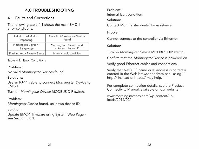
4.0 TROUBLESHOOTING
4.1 Faults and Corrections
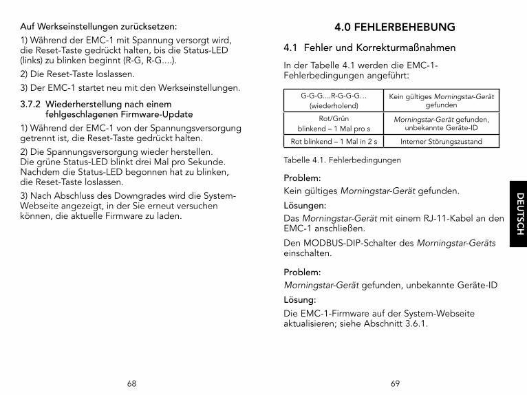
The following table 4.1 shows the main EMC-1 error conditions:
G-G-G....R-G-G-G… (repeating)
No valid Morningstar Devices found
Flashing red / green - 1 every sec
Morningstar Device found, unknown device ID
Flashing red - 1 every 2 secs Internal fault condition
Table 4.1. Error Conditions
Problem:No valid Morningstar Devices found.
Solutions:Use an RJ-11 cable to connect Morningstar Device to EMC-1
Turn on Morningstar Device MODBUS DIP switch.
Problem:Morningstar Device found, unknown device ID
Solution:Update EMC-1 firmware using System Web Page - see Section 3.6.1.
Problem:Internal fault condition
Solution:Contact Morningstar dealer for assistance
Problem:
Cannot connect to the controller via Ethernet
Solutions:
Turn on Morningstar Device MODBUS DIP switch.
Confirm that the Morningstar Device is powered on.
Verify good Ethernet cables and connections.
Verify that NetBIOS name or IP address is correctly entered in the Web browser address bar - using http:// instead of https:// may help.
For complete connection details, see the Product Connectivity Manual, available on our website:
www.morningstarcorp.com/wp-content/up-loads/2014/02/

23 24
5.0 WARRANTY
LIMITED WARRANTY - Morningstar Solar Controllers and Inverters
All Morningstar Professional SeriesTM products, except the SureSineTM inverter, are warrantied to be free from defects in materials and workmanship for a period of FIVE (5) years from the date of shipment to the original end user. Warranty on replaced units, or field-replaced components, will be limited only to the duration of the original product coverage.
Morningstar Essentials SeriesTM, and SureSineTM inverter, products are warrantied to be free from defects in materials and workmanship for a period of TWO (2) years from the date of shipment to the original end user. Warranty on replaced units, or field-replaced components, will be limited only to the duration of the original product coverage.
Morningstar will, at its option, repair or replace any such defective units.
CLAIM PROCEDURE:
Before requesting warranty service, check the Operator’s Manual to verify product failure. Return the defective product to your authorized Morningstar distributor with shipping charges prepaid. Provide proof of date and place of purchase.
An RMA number must be issued by Morningstar prior to return of any unit(s) under this warranty. RMA information must include product model, serial number, detailed failure description, panel type, array size-configuration, type of batteries and system load details. This information is critical to rapid disposition of your warranty claim.
Morningstar will pay the return shipping charges if the repairs are covered under the warranty.
WARRANTY EXCLUSIONS AND LIMITATIONS
This warranty does not apply under the following conditions: • Damage by accident, negligence, abuse or improper use • PV or load currents exceeding the ratings of the product• Unauthorized product modification or attempted repair • Damage occurring during shipment • Damage results from acts of nature such as lightning and weather extremes
THE WARRANTY AND REMEDIES SET FORTH ABOVE ARE EXCLUSIVE AND IN LIEU OF ALL OTHERS, EXPRESS OR IMPLIED. MORNINGSTAR SPECIFICALLY DISCLAIMS ANY AND ALL IMPLIED WARRANTIES, INCLUDING, WITHOUT LIMITATION, WARRANTIES OF MERCHANTABILITY AND FITNESS FOR A PARTICULAR PURPOSE. No Morningstar distributor, agent or employee is authorized to make any modification or extension to this warranty.
MORNINGSTAR IS NOT RESPONSIBLE FOR INCIDENTAL OR CONSEQUENTIAL DAMAGES OF ANY KIND, INCLUD-ING BUT NOT LIMITED TO LOST PROFITS, DOWNTIME, GOODWILL OR DAMAGE TO EQUIPMENT OR PROPERTY.
R15-1/20
25 26
6.0 TECHNICAL SPECIFICATIONS
Electrical:DC input supply voltage range 8-80 VdcSelf-consumption ~2W
Data & Communications:
Communications Ports MeterBus (RJ-11) Ethernet (RJ-45)
COM Protocols Morningstar MeterBus; MODBUS TCP/IP; SNMP
Ethernet Speed 10/100Base-T
Mechanical:IP Indoor, IP20Plastic enclosureDIN-rail mount Standard 35mmWeight (unit only): 0.28 lb / 0.13 kg
Environmental: Operating Temperature Range -40ºC to +60ºC Storage Temperature -55ºC to 80ºCHumidity 100% non-condensing
7.0 CERTIFICATIONS
• C-Tick RCM compliant• FCC Class B compliant
ENs Directives:• Complies with ENs standards for CE marking• Immunity: EN 61000-4-3: 2006 EN 61000- 4-6: 2009• Emissions: CISPR 22: 2008
EMC-1TM and MeterbusTM are trademarks of Morningstar Corporation
MODBUSTM and MODBUS TCP/IPTM are trademarks of Modbus IDA. www.modbus-ida.org
© 2020 Morningstar Corporation. All rights reserved.
MS-001796 v2.6
REACHALL
COMPONENTS
COMPLIANT
Registration, Evaluation andAuthorization of Chemicals
TUVRheinland®
CERTIFIED

Pour les plus récentes révisions du manuel, consultez la dernière version à l’adresse :
www.morningstarcorp.com
Die aktuelle Version des Handbuchs in Deutsch finden Sie unter:
www.morningstarcorp.com
Para obtener las revisiones más recientes del manual, consulte la versión en (español):
www.morningstarcorp.com
Convertisseur MeterBus EthernetEthernet-MeterBus-Umwandler
Convertidor Ethernet para MeterBus
Manuel de l’utilisateur...24Bedienerhandbuch.........49Manual del operador......74
EMC-1 TM
www.morningstarcorp.com

TABLE DES MATIÈRES
1.0 Informations générales ................................... 271.1 Aperçu ............................................................271.2 Caractéristiques ..............................................292.0 Installation ........................................................ 302.1 Montage .........................................................302.2 Configuration .................................................312.3 Connexions ....................................................32 2.3.1 Installation de l’EMC-1 ...................................322.3.2 Installation du TriStar et du TriStar MPPT
à l’aide d’un adaptateur de câble en Y .........322.3.3 TriStar avec application d’appareil de mesure ..332.4 Configuration des commutateurs DIP ............342.4.1 Écritures Ethernet ...........................................342.5 Connexion des câbles d’alimentation ............353.0 Fonctionnement ............................................... 363.1 Voyants DEL ...................................................363.2 Démarrage .....................................................363.3 DEL d’état EMC-1 ..........................................373.4 DEL de service Web .......................................383.5 DEL d’écriture Ethernet ..................................383.6 Connectivité ...................................................383.6.1 MSView...........................................................383.6.2 Pages Web LiveView ......................................39 3.6.3 Connexion à un LAN / WAN ..........................413.6.4 Connexion à l’EMC-1 à partir
d’un emplacement distant .............................413.7 Fonctions de bouton-poussoir .......................423.7.1 Réinitialisation de la configuration usine .......423.7.2 Récupération après la défaillance de
la mise à jour du micrologiciel .......................43
FRA
NÇ
AIS
DIMENSIONS [pouces (millimètres)]
3.37( 86 )
6.04( 153 )
2.17( 55 )
5.51( 140 )
1.20( 30 )
4.85( 123 )
RÉSUMÉ DES SPÉCIFICATIONS
EMC-1
Source d’alimentation requise
Système de batterie pour Dispositif Morningstar, ou
convertisseur CA-CC
Connexion de l’alimentation électrique
requiseTerminaux embarqués
Tension d’entrée 8-80 V CC
Vitesse Ethernet 10/100Base-T

27
1.0 INFORMATIONS GÉNÉRALES
1.1 AperçuL’EMC-1 est un convertisseur MODBUSTM Ethernet vers MeterbusTM qui assure une fonction de passerelle pour une connexion TCP/IP à un onduleur ou un régulateur de charge Morningstar (Dispositif Morningstar) ne possédant pas une connectivité Ethernet intégrée. L’appareil connecté doit être doté d’un port Meterbus (RJ-11).
L’EMC-1 assure une fonction de passerelle Ethernet desservant MODBUS IP, les pages Web locales et les services de surveillance Web. Le service de surveillance Web n’est pas disponible au moment de l’impression de ce document. La connectivité Ethernet permet aux utilisateurs de collecter à distance des informations sur leur système PV autoproducteurs. Les réseaux Ethernet comprennent également des communications LAN (réseaux locaux) et Internet.
L’EMC-1 prend en charge les fonctionnalités de communication suivantes avec un Dispositif Morningstar :
• Surveillance et modifications des paramètres réseau Web Internet de Morningstar LiveViewTM ;
• Surveillance, journalisation et programmation personnalisée à l’aide du logiciel PC Morningstar MSViewTM ;
• (Usage futur) Surveillance Web pour la visibilité et le reporting des données à une tierce partie.
FRA
NÇ
AIS
TABLE DES MATIÈRES (Suite)
4.0 Dépannage ....................................................... 444.1 Erreurs et corrections .....................................445.0 Garantie ......................................................46
6.0 Spécifications techniques ............................... 47
7.0 Certifications .................................................... 48

28 29
1.2 CaractéristiquesLa figure 1-1 ci-dessous présente les caractéristiques du EMC-1. Une présentation de chaque caractéristique est ensuite fournie.
1 - Commutateurs DIPDIP 1 active les commandes d’écriture Ethernet. DIP 2 active le service de surveillance Web (utilisation future) 2 - Bouton de réinitialisationÀ utiliser pour une réinitialisation usine ou en cas d’échec du micrologiciel3 - Port Ethernet (RJ-45)Utilisé pour connecter l’EMC-1 au LAN / Internet4 - Alimentation électriqueAlimentation électrique 8-80 V CC5 - DEL d’étatLes voyants vert et rouge indiquent l’état de l’unité6 - DEL de service de surveillance Web Les voyants vert et rouge indiquent l’état du service Web7 - DEL d’écriture EthernetLe voyant vert indique la fonction de commande d’écriture Ethernet8 - Meterbus (Port RJ-11)Utilisé pour connecter l’EMC-1 au Dispositif Morningstar9 - Montages sur rail DIN (au bas de l’unité)Taille standard 35 mm
5
8
6 7
3
2
4
1
9
2
5
Figure 1-1 Caractéristiques de l’EMC-1
FRA
NÇ
AIS
Le tableau ci-dessous répertorie les produits pris en charge par l’EMC-1, en incluant des détails sur les ports et les données. Pour une liste actualisée, consultez la dernière version du manuel à l’adresse :
www.morningstarcorp.com
Produit Modbus via RJ-11 Port RS-232
Consigne les données historiques
ProStar Gen 3 Oui Non Oui
PS-MPPT-25/M Oui Non Oui
PS-MPPT-40/M Oui Non Oui
SunSaver Duo Oui Non Non
SunSaver-MPPT-15L
Oui Non Oui
SureSine-300 (tous les modèles)
Oui Non Non
TS-45* Non Oui Oui
TS-60* Non Oui Oui
TS-MPPT-30* Non Oui Oui
TS-MPPT-45* Non Oui Oui
TS-MPPT-60* Non Oui Oui
* L’EMC-1 avec câble en Y doit s’alimenter à partir du port RJ-11 pendant la communication via le port RS-232. Voir Section 2.3.2.
Tableau 1.1 Produits pris en charge

30 31
Étape 4Placez l’EMC-1 sur la surface et alignez les trous des pattes de fixation sur les quatre trous de guidage. Utilisez les vis #10 fournies pour fixer l’EMC-1 sur la surface.
Option 2 - Montage sur rail DIN :Vous pouvez également monter l’EMC-1 sur un rail DIN standard de 1-3/8" (35 mm).Étape 1Choisissez le positionnement voulu pour le montage sur rail DIN. Il doit être à l’abri de la lumière directe du soleil, des températures élevées, des vapeurs corrosives et de l’eau. N’installez pas le EMC-1 dans un espace confiné, où les gaz de batterie peuvent s’accumuler.
Étape 2Confirmez que l’espace au-dessus et au-dessous du positionnement de montage sur rail DIN est suffisant pour les connexions de câble de l’EMC-1. Utilisez les vis fournies pour fixer le rail DIN sur la surface voulue.
Étape 3L’EMC-1 est conçu pour une installation sans outil sur un rail DIN. Le bas de l’EMC-1 est doté de quatre crochets qui glissent sur les rampes supérieure et inférieure du rail DIN.
2.2 ConfigurationPour la communication via l’EMC-1, les commutateurs DIP du Dispositif Morningstar doivent, le cas échéant, être configurés pour la communication MODBUS. Sur les produits SunSaver MPPT, ProStar MPPT et SureSine, le commutateur DIP approprié doit être configuré pour la communication MODBUS. Voir Section 2.4 pour en savoir plus sur le réglage des commutateurs DIP de l’EMC-1.
FRA
NÇ
AIS
2.0 INSTALLATION
2.1 MontageL’EMC-1 peut être monté sur un mur, en surface ou sur un rail DIN à l’aide des outils de base :Tournevis à tête plateTournevis cruciformePerceuse (montage sur un mur ou en surface)Mèche de 1/8” (montage sur un mur ou en surface)
Option 1 - Montage sur un mur ou en surface :
Étape 1Positionnez l’EMC-1 sur une surface à l’abri des rayons du soleil, des températures élevées, des vapeurs corrosives et de l’eau. Ne l’installez pas dans un espace confiné, où les gaz de batterie peuvent s’accumuler.
Étape 2Avant de commencer l’installation, placez l’EMC-1 sur la surface où il sera monté et déterminez les points d’entrée et de sortie des fils. Assurez-vous qu’il existe un espace suffisant pour plier les fils et les câbles de communication. Si possible, vérifiez que les vis de montage ne risquent pas de percer les câbles ou autres objets situés sur le côté opposé de la surface.
Étape 3Placez l’EMC-1 sur la surface de montage prévue et marquez quatre trous pour le perçage. Retirez l’EMC-1 de la surface et, à l’aide d’une mèche de 1/8", percez les trous de guidage pour chacune des quatre vis de montage, comme indiqué sur la surface.
32 33
2.3 Connexions
2.3.1 Installation de l’EMC-1
REMARQUE : Veillez à effectuer les connexions COM lorsque le dispositif est hors tensionInsérez un câble Ethernet (A) dans la prise RJ-45 de l’EMC-1. Insérez la fiche placée à une extrémité d’un câble RJ-11 à six conducteurs (B) dans la prise RJ-11 de l’EMC-1. Insérez la fiche placée à l’autre extrémité du câble RJ-11 dans le port RJ-11 du Dispositif Morningstar. Voir la section Fonctionnement (3) pour plus de détails sur la procédure de démarrage.
Figure 2-1. Connexion des câbles COM
2.3.2 Installation du TriStar et du TriStar MPPT à l’aide d’un adaptateur de câble en Y
Pour communiquer avec l’EMC-1, les régulateurs TriStar et TriStar MPPT doivent être installés à l’aide de l’adaptateur de câble en Y fourni. Les fiches RS-232 série et RJ-11 sont reliées au régulateur, et l’autre fiche RJ-11 à l’EMC-1.
A
BRJ-45
RJ-11Remarque : E�ectuez les connexions COM avec le dispositif hors tension
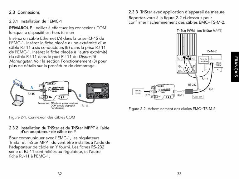
2.3.3 TriStar avec application d’appareil de mesure Reportez-vous à la figure 2-2 ci-dessous pour confirmer l’acheminement des câbles EMC−TS-M-2.
Figure 2-2. Acheminement des câbles EMC−TS-M-2
TS-M-2
TriStar PWM (ou TriStar MPPT)
RJ-11RJ-45
RJ-11
RJ-11
RS-232
PriseTriStar
Prise decompteur
Câble en Y
Vers leréseau
FRA
NÇ
AIS

34 35
2.5 Connexion des câbles d’alimentationLe EMC-1 est alimenté par une source 8-80 V CC, par exemple un convertisseur CA-CC ou une batterie système connectée à l’entrée sur l’unité EMC-1. Voir la section Fonctionnement (3) pour plus de détails sur la procédure de démarrage. Branchez les câbles d’alimentation comme indiqué dans la figure 2-4 ci-dessous.
Figure 2-4. Connexion des câbles d’alimentation
REMARQUE : Le Dispositif Morningstar alimentera l’EMC-1 via le port Meterbus, mais cette alimentation ne sera peut-être pas suffisante pour toutes les conditions de fonctionnement. L’alimentation 8-80 V est requise pour garantir une alimentation constante et fiable.
OK!
Fusible de 5 A etsupport de 4 podepuis (I) la bornede batterie
Remarque : L'EMC 1 démarrera avec une connexion RJ 11 à un Dispositif Morningstar activé ou avec une alimentation directe au EMC 1
FRA
NÇ
AIS
2.4 Configuration des commutateurs DIPLa figure 2-3 ci-dessous montre l’emplacement et les fonctions des commutateurs DIP :
Figure 2-3. Fonctions des commutateurs DIP
2.4.1 Écritures Ethernet
Lorsque le mode DIP 1 est activé, les écritures Ethernet sont activées. Les programmes personnalisés, les mises à jour du micrologiciel (sur l’EMC-1) et les paramètres réseau peuvent ainsi être écrits sur un Dispositif Morningstar. Bien que ce commutateur DIP soit un dispositif de sécurité visant à prévenir toute modification accidentelle de la configuration sur le Dispositif Morningstar, le mode DIP 1 n’est pas un substitut pour une sécurité du réseau adéquate.
DIP 1 ACTIVÉ (relevé)Permet les écrituresEternet
DIP 2 - Usage futur

36 37
SÉQUENCE DE DÉMARRAGE DE L’EMC-1 (avec Dispositif MS connecté)
DEL d’état clignotante V
DEL activées pendant 3 secondes V + V + (V)
Une fois l’EMC-1 alimenté et le câble RJ-45 connecté, les DEL RJ-45 s’allument comme indiqué dans le tableau ci-dessous.
INDICATIONS DE PRISE ETHERNET
État DEL verte DEL jaune
Connexion réseau OK ACTIVÉ DÉSACTIVÉ
Activité réseau ACTIVÉ Clignotement
Erreur DÉSACTIVÉ ACTIVÉ
3.3 DEL d’état de l’EMC-1 (verte et rouge)Vert clignotant : 1 fois
par seconde. Peut ne pas apparaître si le Dispositif
MS est détecté rapidement
Recherche du Dispositif Morningstar
Vert solide (pulsation désactivée)
Dispositif Morningstar détecté, communication en cours
V-V-V....R-V-V-V (répétition)
Pas de Dispositifs Morningstar valides détectés
Rouge clignotant - vert : Toutes les secondes
Dispositif Morningstar détecté, ID de dispositif inconnu - mise à jour du
micrologiciel de l’EMC-1
Vert clignotant : Toutes les 3 secondes
Mise à jour du micrologiciel ou passage à une version antérieure en cours Vous ne devez pas mettre le Dispositif hors tension tant que cet
état est activé.
Rouge clignotant : 1 fois toutes les 2 secondes Erreur interne
FRA
NÇ
AIS
3.0 FONCTIONNEMENT
3.1 Voyants DELL’EMC-1 est doté de trois voyant DEL (voir la figure 3-1 ci-dessous), qui en indiquent tous les états. De gauche à droite : DEL d’état (vert / rouge) ; DEL du service Web (vert / rouge) ; DEL d’activation de l’écriture Ethernet (vert).
Figure 3-1. Voyants DEL
3.2 Démarrage
À l’issue de l’installation, comme décrit à la section 2.3.1, l’EMC-1 est démarré par branchement à l’alimentation, comme décrit à la section 2.5.
Au démarrage, la DEL d’état clignote une fois en vert, puis toutes les DEL [vert, vert, (vert)] s’allument en même temps pendant trois secondes. L’EMC-1 commence ensuite à rechercher automatiquement des Dispositifs Morningstar valides. Le cas échéant, le commutateur DIP MODBUS du Dispositif Morningstar doit être activé pour permettre l’établissement de la connexion.
État EMC 1État
Service Web
État Écriture Eternet

38 39
L’onglet Device (Dispositif) dans MSView peut être utilisé pour « Rechercher les Dispositifs connectés .» L’écran de recherche indique le Dispositif Morningstar, son numéro de série de 8 chiffres et l’adresse IP courante de l’EMC-1 / du Dispositif Morningstar. L’adresse IP peut ensuite être utilisée pour visualiser les pages Web, comme décrit à la section 3.6.2 ci-dessous. L’unité possède l’adresse IP par défaut suivante : 192.168.1.253
3.6.2 Pages Web LiveView Avec un navigateur Web, l’EMC-1 offre deux méthodes pour accéder aux pages Web LiveView d’un Dispositif Morningstar :1) Entrez l’adresse IP du Dispositif Morningstar dans la barre d’adresse, par exemple http://192.168.1.186
2) Entrez le nom NetBIOS du Dispositif Morningstar [abréviation du produit + numéro de série de 8 chiffres] dans la barre d’adresse, par exemple http://ssmppt15320850
Abréviations NetBIOS des produits :
TriStar MPPT tsmppt
ProStar MPPT psmppt
ProStar Gen 3 pspwm
SunSaver MPPT ssmppt
TriStar PWM ts
SunSaver Duo ssduo
SureSine suresine
FRA
NÇ
AIS
3.4 (Utilisation future) Réglage des DIP du service Web et voyants DEL (vert / rouge)
À déterminer Diffusions désactivéesÀ déterminer Diffusions activées
À déterminer Recherche du serveur / établissement de la connexion
À déterminer Connexion établie / diffusionÀ déterminer Impossible d’établir une connexion au serveurÀ déterminer À déterminer
À déterminer Informations d’identification de connexion non valides* (connecté au serveur)
* Erreur de connexion et/ou d’inscription de serveur
3.5 DEL d’écriture Ethernet (verte)
DIP 1 DÉSACTIVÉ (vert DÉSACTIVÉ)
Écritures Ethernet désactivées
DIP 1 ACTIVÉ (vert ACTIVÉ) Écritures Ethernet activées
3.6 Connectivité3.6.1 MSViewMSView est un utilitaire logiciel Morningstar qui assure en temps réel la transmission des données système à un PC, permettant de programmer les paramètres de charge et de consigner les données. MSView peut être téléchargé gratuitement depuis : www.morningstarcorp.com/msview/ Pour des détails de connexion complets, reportez-vous au Manuel de connectivité produit, disponible sur notre site Web :www.morningstarcorp.com/wp-content/uploads/2014/02/

40 41
3.6.3 Connexion à un LAN / WANAprès l’installation de MSView sur un PC connecté à un réseau local et l’établissement des connexions COM et d’alimentation, comme décrit dans les sections 2.3, 2.4, un routeur activé en DHCP affectera automatiquement une adresse IP et des paramètres réseau à l’EMC-1. Le Dispositif Morningstar fera également l’objet d’une consultation destinée à déterminer les informations spécifiques du dispositif avant l’établissement de la connexion. Après l’affectation initiale, vous pouvez modifier à votre convenance les paramètres du réseau dans la page Web Network (Réseau) de LiveView.Pour obtenir des informations complètes sur les connexions et l’adressage, voir l’Annexe I du Manuel de connectivité produit : www.morningstarcorp.com/wp-content/uploads/2014/02/
RUBRIQUE AVANCÉE :3.6.4 Connexion à l’EMC-1 à partir d’un
emplacement distant (hors du LAN) via Internet / WAN
Procédure de base :
1. Assurez-vous que le Dispositif Morningstar est bien connecté : accédez au dispositif via un navigateur Web (voir Section 3.6.2). Naviguez jusqu’à la page Network (Réseau).
2. Dans une autre fenêtre de navigateur, saisissez l’adresse IP de la passerelle par défaut du routeur réseau (il s’agit probablement de l’adresse 192.168.1.1, mais consultez l’Annexe I, Section II du Manuel de connectivité produit - lien ci-dessous).
FRA
NÇ
AIS
REMARQUE : De nombreux réseaux sont activés en DHCP, et l’affectation de l’adresse IP change après un certain temps. L’adresse NetBIOS est un identifiant statique du Dispositif Morningstar, qui pointe toujours vers le Dispositif Morningstar.
Après la connexion au serveur LiveView, les pages Web suivantes sont disponibles pour la visualisation :
LiveViewIl s’agit de la page Web par défaut, qui affiche en temps réel les données système, les erreurs et les alarmes de base.
Network (Réseau)Cette page Web affiche les paramètres réseau actuels du Dispositif Morningstar et permet de modifier les paramètres COM et le réacheminement de port :DHCP DNS principalAdresse IP Port IP Modbus 502Masque de ID de Dispositif par défaut sous-réseau (MODBUS)Passerelle Port HTTP 80
Data Log (Journal de données)Cette page Web affiche le jour courant et des informations système historiques détaillées pour une période spécifique, en fonction du nombre de variables définies pour la journalisation.
System (Système) Cette page est utilisée pour mettre à jour le micrologiciel de l’EMC-1. Le micrologiciel du dispositif connecté ne peut pas être mis à jour à partir de la page Web System (Système). La page Web System (Système) affiche également des informations de diagnostic spécifiques pour l’EMC-1.

42 43
Pour effectuer une réinitialisation usine :1) Mettez l’EMC-1 sous tension, appuyez sur le bouton de réinitialisation et maintenez-le enfoncé jusqu’à ce que la DEL d’état (gauche) se mette à clignoter selon la séquence R-V, R-V.... 2) Relâchez le bouton de réinitialisation.3) L’EMC-1 est réinitialisé et les paramètres usine par défaut sont rétablis.
3.7.2 Récupération après la défaillance de la mise à jour du micrologiciel
1) Mettez l’EMC-1 hors tension, puis appuyez sur le bouton de réinitialisation et maintenez-le enfoncé. 2) Remettez sous tension ; la DEL d’état verte se met à clignoter trois fois par seconde. Relâchez le bouton de réinitialisation une fois que le clignotement a commencé. 3) Le rétablissement d’une version antérieure commence. Une fois cette opération terminée, l’EMC-1 ouvre la page Web System (Système) et permet à l’utilisateur de tenter une nouvelle fois de charger le nouveau micrologiciel.
FRA
NÇ
AIS
3. Établissez une connexion au routeur réseau et choisissez une adresse IP statique hors de la plage dynamique indiquée.
4. Revenez à la page Network (Réseau) de LiveView, passez la sélection à « Use Static IP Address » (Utiliser une adresse IP statique), entrez l’adresse IP choisie à l’étape précédente, entrez une nouvelle fois les autres paramètres de réseau indiqués dans la zone, dont le port 502, afin de diriger les requêtes Internet vers le Dispositif Morningstar, et le port 80 afin de visualiser les pages Web du Dispositif Morningstar sur tout PC connecté à Internet, puis cliquez sur le bouton « Save » (Enregistrer).
5. Pour conserver une adresse IP publique reconnaissable, configurez un service DNS dynamique, ou vérifiez la fonction DNS dynamique du routeur.
Le Manuel de connectivité produit décrit tous les aspects de connectivité et de programmation : www.morningstarcorp.com/wp-content/uploads/2014/02/ Voir l’Annexe 1, Section 3 pour plus de détails.
3.7 Fonctions de bouton-poussoir3.7.1 Réinitialisation usineVous pouvez rétablir les paramètres de communication définis par défaut en usine pour l’EMC-1. Les valeurs suivantes seront rétablies :
• Paramètres TCP / IP• Données produit non volatiles mémorisées

44 45
Problème :Erreur interne
Solution :Contactez votre revendeur Morningstar pour assistance
Problème :
Impossible d’établir une connexion au régulateur via Ethernet
Solutions :
Activez le commutateur DIP MODBUS du Dispositif Morningstar.
Confirmez que le Dispositif Morningstar est sous tension.
Vérifiez les câbles et les connexions Ethernet.
Vérifiez que le nom NetBIOS ou l’adresse IP est correctement saisi dans la barre d’adresse du navigateur Web. Il peut être utile de replacer http:// par https://.
Pour des détails complets sur la connexion, reportez-vous au Manuel de connectivité produit, disponible sur notre site Web :
www.morningstarcorp.com/wp-content/uploads/2014/02/
FRA
NÇ
AIS
4.0 DÉPANNAGE
4.1 Erreurs et corrections
Le tableau 4.1 ci-dessous indique les principales conditions d’erreur de l’EMC-1 :
V-V-V....R-V-V-V… (répétition)
Pas de Dispositifs Morningstar valides détectés
Rouge / vert clignotant -1 fois toutes les secondes
Dispositif Morningstar détecté, ID de dispositif inconnu
Rouge clignotant - 1 fois toutes les 2 secondes Erreur interne
Tableau 4.1. Conditions d’erreur
Problème :Pas de Dispositifs Morningstar valides détectés.
Solutions :Utilisez un câble RJ-11 pour connecter le Dispositif Morningstar à l’EMC-1
Activez le commutateur DIP MODBUS du Dispositif Morningstar.
Problème :Dispositif Morningstar détecté, ID de dispositif inconnu
Solution :Mettez à jour le micrologiciel de l’EMC-1 dans la page Web System (Système) - Voir Section 3.6.1.

46 47
6.0 CARACTÉRISTIQUES TECHNIQUES
Caractéristiques électriques :Plage de tensions d’alimentation en entrée 8-80 V CC
Auto-consommation ~2 W
Données et communications :Ports de communication MeterBus (RJ-11)
Ethernet (RJ-45)Protocoles COM Morningstar MeterBus ;
MODBUS TCP/IP; SNMPVitesse Ethernet 10/100Base-T
Caractéristiques mécaniques :IP Indoor, IP20Enceinte en plastiqueMontage sur rail DIN 35 mm standardPoids (unité uniquement) : 0,28 lb / 0,13 kg
Caractéristiques environnementales :Plage de températures de fonctionnement -40 ºC à +60 ºC
Température de stockage -55 ºC à 80 ºCHumidité 100 % sans condensation
FRA
NÇ
AIS
5.0 GARANTIE
GARANTIE LIMITÉE
Morningstar garantit que l’EMC-1 est exempt de tout défaut de matériaux et de fabrication pendant une période de CINQ (5) ans à compter de la date de livraison à l’utilisateur final d’origine. Morningstar pourra, à sa discrétion, réparer ou remplacer les unités défectueuses.
EXCLUSIONS ET LIMITATIONS DE GARANTIE :
Cette garantie ne s’applique pas dans les conditions suivantes :
♦ Dommages résultant d’un accident, d’une négligence, d’un usage abusif ou d’une utilisation incorrecte
♦ Courants PV ou de charge excédant les capacités nominales du produit♦ Modifications ou tentatives de réparation non autorisées du produit♦ Dommages survenus au cours de l’expédition♦ Dommages résultant de phénomènes naturels, comme la foudre et les
conditions météorologiques extrêmes
LA GARANTIE ET LES RECOURS ÉNONCÉS CI-DESSUS SONT EXCLUSIFS ET REMPLACENT TOUS LES AUTRES, EXPLICITES OU IMPLICITES. MORNINGSTAR DÉCLINE SPÉCIFIQUEMENT TOUTES LES GARANTIES IMPLICITES, Y COMPRIS, SANS LIMITATION, LES GARANTIES DE QUALITÉ MARCHANDE ET D’ADÉQUATION À UN USAGE PARTICULIER. AUCUN DISTRIBUTEUR, AGENT OU EMPLOYÉ MORNINGSTAR N’EST AUTORISÉ À APPORTER DES MODIFICATIONS OU EXTENSIONS À CETTE GARANTIE.
MORNINGSTAR N’ASSUME AUCUNE RESPONSABILITÉ POUR LES DOMMAGES ACCESSOIRES OU INDIRECTS DE TOUTE NATURE, Y COMPRIS, SANS LIMITATION, LA PERTE DE PROFITS, LES TEMPS D’IMMOBILISATION, LA PERTE DE CLIENTÈLE OU LES DOMMAGES DU MATÉRIEL OU DES BIENS.
R17-8/16

48
7.0 CERTIFICATIONS
• Conforme à la norme C-Tick RCM• Conforme à la norme FCC Classe B
Directives EN :• Conforme aux normes EN pour le marquage CE• Immunité : EN 61000-4-3 : 2006 EN 61000- 4-6 : 2009• Émissions : CISPR 22 : 2008
EMC-1TM et MeterbusTM sont des marques commercia-les de Morningstar Corporation
MODBUSTM et MODBUS TCP/IPTM sont des marques commerciales de Modbus IDA. www.modbus-ida.org
© 2020 Morningstar Corporation. Tous droits réservés.
MS-001796 v2.6
REACHALL
COMPONENTS
COMPLIANT
Registration, Evaluation andAuthorization of Chemicals
TUVRheinland®
CERTIFIED
ABMESSUNGEN (mm)
86
153
55
140
30
123
TECHNISCHE DATEN
EMC-1
Spannungsversorgung Morningstar-Systembatterie oder AC/DC-Wandler
Anschluss Onboard-Klemmen
Eingangsspannung 8-80 Vdc
Ethernet-Geschwindigkeit 10/100Base-T
DE
UTSC
H

INHALT (Fortsetzung)
4.0 Fehlerbehebung ...............................................69 4.1 Fehler und Korrekturmaßnahmen ................... 695.0 Gewährleistung ................................................716.0 Technische Daten .............................................727.0 Zertifizierungen ................................................73
DE
UTSC
H
INHALT
1.0 Allgemeine Informationen ...............................521.1 Überblick .......................................................... 521.2 Ausstattung ...................................................... 542.0 Installation ........................................................552.1 Montage .......................................................... 552.2 Konfiguration ................................................... 572.3 Verbindungen .................................................. 57 2.3.1 Installation des EMC-1..................................... 572.3.2 Installation von TriStar und TriStar MPPT
mit Y-Kabeladapter............................................. 582.3.3 TriStar mit Messgerät ......................................... 582.4 Einstellung der DIP-Schalter ............................ 592.4.1 Ethernet-Schreibbefehle .................................. 592.5 Anschließen der
Spannungsversorgungsleitungen .................... 603.0 Betrieb ..............................................................61 3.1 LED-Anzeigen .................................................. 61 3.2 Inbetriebnahme ............................................... 613.3 EMC-1-Status-LEDs ......................................... 623.4 Webdienst-LEDs .............................................. 633.5 LED für Ethernet-Schreibbefehle ..................... 633.6 Konnektivität .................................................... 633.6.1 MSView ............................................................ 633.6.2 LiveView-Webseiten ........................................ 643.6.3 Anschließen an ein LAN/WAN ........................ 663.6.4 Remote-Verbindungsherstellung
mit dem EMC-1 ............................................... 663.7 Funktionen der Reset-Taste ............................. 673.7.1 Zurücksetzen auf Werkseinstellungen ............. 673.7.2 Wiederherstellung nach einem
fehlgeschlagenen Firmware-Update................ 68

52 53
In der folgenden Tabelle werden die von EMC-1 unterstützten Produkte sowie Angaben zu Anschlüssen und zur Datenprotokollierung aufgelistet. Die aktuelle Liste finden Sie in der neusten Handbuchversion unter:
www.morningstarcorp.com
Produkt Modbus über RJ-11
RS-232-Anschluss
Protokollierung von historischen
DatenProStar Gen 3 Ja Nein Ja
PS-MPPT-25/M Ja Nein Ja
PS-MPPT-40/M Ja Nein Ja
SunSaver Duo Ja Nein Nein
SunSaver-MPPT-15L
Ja Nein Ja
SureSine-300 (alle Modelle)
Ja Nein Nein
TS-45* Nein Ja Ja
TS-60* Nein Ja Ja
TS-MPPT-30* Nein Ja Ja
TS-MPPT-45* Nein Ja Ja
TS-MPPT-60* Nein Ja Ja
* Das dem EMC-1 beiliegende Y-Kabel dient der Spannungsversorgung über den RJ-11-Anschluss, während über den RS-232-Anschluss kommuniziert wird. Siehe Abschnitt 2.3.2.
Tabelle 1-1 Unterstützte Produkte
DE
UTSC
H
1.0 ALLGEMEINE INFORMATIONEN
1.1 ÜberblickDer EMC-1 ist ein MODBUSTM-Ethernet-zu-MeterbusTM-Konverter, der eine TCP/IP-Verbindung zwischen einem Morningstar-Laderegler oder -Wechselrichter (Morningstar-Gerät) ermöglicht, der nicht Ethernet-fähig ist. Das anzuschließende Gerät muss einen Meterbus- (RJ-11) Anschluss besitzen.
Der EMC-1 dient als Ethernet-Gateway, das MODBUS-IP, Web-Überwachungsdienste und den Abruf lokaler Webseiten ermöglicht. Die Web-Überwachungsdienste stehen zum Zeitpunkt der Veröffentlichung dieses Dokuments noch nicht zur Verfügung. Die Ethernet-Verbindung ermöglicht den Anwendern den entfernten Zugriff auf ihre netzunabhängigen PV-Anlagen. Ethernet ermöglicht weiterhin eine Kommunikation über Local Area Networks (LANs) und das Internet.
Der EMC-1 bietet die folgenden Kommunikationsfunktionen bei einem Morningstar-Gerät:
• Morningstar LiveViewTM-Webüberwachung und Änderung von Netzwerkeinstellungen
• Überwachung, Protokollierung und Programmierung mit der Morningstar MSViewTM-PC-Software
• (Zukünftig verfügbar) Erstellung von Berichten und Sichtbarkeit für Dritte.

5554
2.0 INSTALLATION
2.1 MontageDer EMC-1 eignet sich zur Wand-, Oberflächen- und DIN-Schienenmontage mit folgendem Standardwerkzeug:SchlitzschraubendreherKreuzschlitzschraubendreherBohrmaschine (bei Wand- oder Oberflächenmontage)3-mm-Bohrer (bei Wand- oder Oberflächenmontage)
Option 1 - Wand- und Oberflächenmontage:
Schritt 1Den EMC-1 an einer Stelle anbringen, an der der er keinem direkten Sonnenlicht und Wasser und keinen hohen Temperaturen und ätzenden Dämpfen ausgesetzt ist. Den EMC-1 nicht in engen Räumen installieren, in denen sich Batteriegase ansammeln können.
Schritt 2Einen geeigneten Ort für die Installation des EMC-1 bestimmen, bei dem genug Platz für die Krümmung der ein- und ausgehenden Leitungen und Kommunikationskabel bleibt. Wenn möglich, vor dem Bohren in die Wand überprüfen, ob sich an der Bohrstelle Leitungen oder andere Objekte in der Wand befinden.
Schritt 3Den EMC-1 an der gewünschten Stelle platzieren und vier Bohrlöcher markieren. Den EMC-1 entfernen und Vorbohrungen mit einem 3-mm-Bohrer an den vier Markierungen durchführen.
DE
UTSC
H
1.2 AusstattungDie Ausstattung des EMC-1 wird in der folgenden Abbildung 1-1 dargestellt. Es folgt eine Beschreibung der einzelnen Elemente.
1 - DIP-SchalterDIP 1 aktiviert Ethernet-Schreibbefehle DIP 2 aktiviert den Webüberwachungsdienst (zukünftig verfügbar) 2 - Reset-TasteZur Zurücksetzung auf Werkseinstellungen oder Wiederherstellung nach Firmware-Fehler3 - Ethernet-Anschluss (RJ-45)Zum Anschluss des EMC-1 an LAN/Internet4 - SpannungsversorgungsanschlussFür 8-80 V (Gleichspannung)5 - Status-LEDGrün oder rot leuchtende Anzeige für den Gerätestatus6 - Webüberwachungsdienst-LED Grün oder rot leuchtende Anzeige für den Webdienststatus7 - Ethernet-Schreib-LEDGrüne Anzeige zeigt die Ausführbarkeit von Ethernet-Schreibbefehlen an8 - Meterbus (RJ-11-Anschluss)Zum Anschluss des EMC-1 an ein Morningstar-Gerät9 - DIN-Tragschienen (Geräteunterseite)35-mm-Normgröße
5
8
6 7
3
2
4
1
9
2
5Abbildung 1-1. Ausstattung des EMC-1

56 57
2.2 KonfigurationDamit der EMC-1 mit dem Morningstar-Gerät kommunizieren kann, müssen ggf. die DIP-Schalter auf MODBUS-Kommunikation eingestellt sein. Bei den Produkten SunSaver MPPT, ProStar MPPT und SureSine müssen die entsprechenden DIP-Schalter auf MODBUS-Kommunikation eingestellt sein. Siehe Abschnitt 2.4 für DIP-Schaltereinstellungen des EMC-1.
2.3 Verbindungen
2.3.1 Installation des EMC-1
HINWEIS: Beim Herstellen der COM-Verbindungen darf keine Spannung anliegen.Das Ethernet-Kabel (A) an die RJ-45-Buchse des EMC-1 anschließen. Den Stecker an einem Ende des RJ-11-Kabels (B) in die RJ-11-Buchse am EMC-1 einstecken. Den Stecker am anderen Ende des RJ-11-Kabels (B) in die RJ-11-Buchse des Morningstar-Geräts einstecken. Die Inbetriebnahme wird im Abschnitt 3 beschrieben.
Abbildung 2-1. Anschluss der COM-Kabel
A
BRJ-45
RJ-11HINWEIS: Beim Herstellen der COM-Verbindungen darf keine Spannung anliegen.
DE
UTSC
H
Schritt 4
Den EMC-1 an der Wand platzieren und die vier Montagefußlöcher mit den Vorbohrlöchern ausrichten. Dann den EMC-1 mit den beiliegenden 10er-Schrauben an der Wand befestigen.
Option 2 - DIN-Schienenmontage:
Der EMC-1 kann auch an einer 35-mm-DIN-Schiene montiert werden.
Schritt 1
Eine geeignete Montagestelle auswählen. Den EMC-1 an einer Stelle anbringen, an der er keinem direkten Sonnenlicht und Wasser und keinen hohen Temperaturen und ätzenden Dämpfen ausgesetzt ist. Den EMC-1 EMC-1nicht in engen Räumen installieren, in denen sich Batteriegase ansammeln können.
Schritt 2
Sicherstellen, dass über und unter der Montagestelle genug Platz für die Kabelverbindungen des EMC-1 vorhanden ist. Die DIN-Schiene mit Schrauben an der gewünschten Montagestelle befestigen.
Schritt 3
Für die Montage des EMC-1 an einer DIN-Schiene ist kein Werkzeug erforderlich. Den EMC-1 auf die DIN-Schiene schieben, wobei der EMC-1 durch die vier Haken an der EMC-1-Unterseite gehalten wird.
58 59
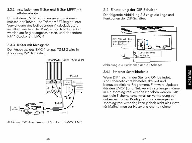
2.4 Einstellung der DIP-SchalterDie folgende Abbildung 2-3 zeigt die Lage und Funktionen der DIP-Schalter:
Abbildung 2-3. Funktionen der DIP-Schalter
2.4.1 Ethernet-Schreibbefehle
Wenn DIP 1 sich in der Stellung ON befindet, sind Ethernet-Schreibbefehle aktiviert und benutzerdefinierte Programme, Firmware-Updates (für den EMC-1) und Netzwerk-Einstellungen können in ein Morningstar-Gerät geschrieben werden. DIP 1 stellt ein Sicherheitsmerkmal zur Vermeidung von unbeabsichtigten Konfigurationsänderungen am Morningstar-Gerät dar, kann jedoch nicht als Ersatz für Maßnahmen zur Netzwerksicherheit dienen.
DIP 1 ON (nach oben) - ermöglicht Ethernet-Schreibbefehle
DIP 2 - zukünftigverfügbar
DE
UTSC
H
2.3.2 Installation von TriStar und TriStar MPPT mit Y-Kabeladapter
Um mit dem EMC-1 kommunizieren zu können, müssen der TriStar- und TriStar MPPT-Regler unter Verwendung des beiliegenden Y-Kabeladapters installiert werden. Der RS-232- und RJ-11-Stecker werden am Regler angeschlossen, und der andere RJ-11-Stecker am EMC-1.
2.3.3 TriStar mit Messgerät Der Anschluss des EMC-1 an das TS-M-2 wird in Abbildung 2-2 dargestellt.
Abbildung 2-2. Anschluss von EMC-1 an TS-M-22. EMC
TS-M-2
TriStar PWM (or TriStar MPPT)
RJ-11RJ-45
RJ-11
RJ-11
RS-232
Meter Jack
TriStar Jack
Y-cable
To Network
TS-M-2
TriStar PWM (oder TriStar MPPT)
RJ-11RJ-45
RJ-11
RJ-11
RS-232
Messgerät-Anschluss
TriStar-Anschluss
Y-Kabel
AnsNetzwerk

60 61
3.0 BETRIEB
3.1 LED-AnzeigenDie Zustände des EMC-1 werden mit drei LED-Anzeigen signalisiert; siehe folgende Abbildung 3-1. Von links nach rechts: Status-LED (Grün/Rot), Webdienst-LED (Grün/Rot), LED für Ethernet-Schreibbefehle aktiviert (Grün).
Abbildung 3-1. LED-Anzeigen
3.2 Inbetriebnahme
Nach der Installation des EMC-1 gemäß Abschnitt 2.3.1 wird das Gerät in Betrieb genommen, indem die Spannungsversorgung gemäß Abschnitt 2.5 angeschlossen wird. Beim Starten blinkt die Status-LED ein Mal grün, und dann leuchten alle LEDs [Grün, Grün, (Grün)] gleichzeitig für drei Sekunden. Danach sucht der EMC-1 automatisch nach gültigen Morningstar-Geräten. Wenn das Morningstar-Gerät einen MODBUS-DIP-Schalter hat, muss dieser für die herzustellende Verbindung eingeschaltet sein.
EMC-1- Status Webdienst-
Status
Ethernet- Schreibbefehl- Status
DE
UTSC
H
2.5 Anschließen der Spannungsversorgungsleitungen
Der EMC-1 wird durch eine 8-80-Vdc-Spannungsversorgung gespeist, z. B. ein AC/DC-Wandler oder eine Systembatterie, die an die entsprechenden Klemmen am EMC-1 angeschossen wird. Die Inbetriebnahme wird im Abschnitt 3 beschrieben. Die Spannungsversorgungsleitungen wie in Abbildung 2-4 gezeigt anschließen.
Abbildung 2-4. Anschluss an Spannungsversorgungsleitungen
HINWEIS: Das Morningstar-Gerät versorgt den EMC-1 über den Meterbus-Anschluss mit Strom, der jedoch unter bestimmten Betriebsbedingungen nicht hoch genug sein kann. Die 8-80 V Spannungsversorgung muss zuverlässig eine konstante Spannung liefern können.
OK!
5 A Sicherung undHalterung - 10 cmvom Pluspol derBatterie entfernt
HINWEIS: Der EMC-1 wird über eine RJ-11-Verbindung mit einemeingeschalteten Morningstar-Gerätoder über einen direkten Anschlussdes EMC-1 an eine Stromquelle eingeschaltet.

62 63
3.4 (Zukünftig verfügbar) Webdienst-DIP-Einstellungen und LED-Anzeige (Grün/Rot)
Noch nicht definiert Übertragung deaktiviert
Noch nicht definiert Übertragung aktiviert
Noch nicht definiert Suche nach Server/Verbindungsherstellung läuft
Noch nicht definiertVerbindung hergestellt/Daten werden
übertragen
Noch nicht definiertVerbindung mit Server kann nicht
hergestellt werden
Noch nicht definiert Noch nicht definiert
Noch nicht definiertUngültige Anmeldeinformationen* (Verbindung mit Server hergestellt)
*Anmelde- und/oder Serverregistrierungsfehler
3.5 LED für Ethernet-Schreibbefehle (Grün)
DIP 1 OFF (Grün, aus) Ethernet-Schreibbefehle deaktiviert
DIP 1 ON (Grün, ein) Ethernet-Schreibbefehle aktiviert
3.6 Konnektivität 3.6.1 MSViewMSView ist ein Dienstprogramm von Morningstar, mit dem Echtzeit-Systemdaten auf einem PC angezeigt, Ladeparameter eingestellt und Daten protokolliert werden können. MSView kann kostenlos unter der folgenden Adresse heruntergeladen werden: www.morningstarcorp.com/msview/ Ausführliche Informationen zur Konnektivität finden Sie im Product Connectivity Manual, das auf unserer Website zur Verfügung steht:www.morningstarcorp.com/wp-content/uploads/2014/02/
DE
UTSC
H
EMC-1-START-SEQUENZ (mit angeschlossenem MS-Gerät)
Status-LED blinkt 1 Mal G
LEDs leuchten für 3 s G + G + (G)
Die RJ-45-LEDs leuchten gemäß der folgenden Tabelle, wenn der EMC-1 mit Spannung versorgt und das RJ-45-Kabel angeschlossen ist.
ETHERNET-ANSCHLUSS-ANZEIGEN
Zustand Grüne LED Gelbe LED
Netzwerkverbindung OK LEUCHTET AUS
Netzwerkaktivität LEUCHTET Blinkend
Fehler AUS LEUCHTET
3.3 EMC-1-Status-LEDs (grün und rot)
Grün blinkend: 1 Mal pros – nicht blinkend, wenn MS-Gerät schnell gefunden wird
Suche nach Morningstar-Gerät läuft
Dauerhaft grün leuchtendMorningstar-Gerät gefunden,
kommuniziert
G-G-G....R-G-G-G… (wiederholend)
Kein gültiges Morningstar-Gerät gefunden
Rot/grün blinkend: 1 Mal pro s
Morningstar-Gerät gefunden, unbekannte Geräte-ID –EMC-1-
Firmware aktualisieren
Grün blinkend: 3 Mal pro s
Firmware-Upgrade oder -Downgrade läuft. In
diesem Zustand darf die Spannungsversorgung nicht
unterbrochen werden.
Rot blinkend: 1 Mal pro 2 s Interner Störungszustand

6564
HINWEIS: Viele Netzwerke sind DHCP-aktiviert, und die IP-Adressenzuweisung ändert sich nach einiger Zeit. Die NetBIOS-Adresse ist eine statische Morningstar-Geräte-Kennzeichnung und verweist stets auf das Morningstar-Gerät.
Nach der Herstellung der Verbindung zum LiveView-Server können die folgenden Webseiten angezeigt werden:
LiveViewAuf dieser Standardseite werden Echtzeit-Systemdaten, Störungen und Alarme angezeigt.
NetworkAuf dieser Seite werden die aktuellen Netzwerkeinstellungen des Morningstar-Geräts angezeigt und können COM-Einstellungen und die Portweiterleitung geändert werden:
DHCP Primärer DNSIP Address Modbus IP Port 502Subnet Mask Standardgeräte-ID (MODBUS)Gateway HTTP Port 80
DatenprotokollierungAuf dieser Webseite werden das aktuelle Datum und detaillierte historische Systeminformationen für einen bestimmten Zeitraum angezeigt, und zwar abhängig von den eingestellten Protokollierungsvariablen.
System Auf der System-Webseite kann die EMC-1-Firmware aktualisiert werden. Die Firmware des angeschlossenen Geräts kann nicht auf der System-Webseite aktualisiert werden. Auf der System-Webseite werden auch spezifische EMC-1-Diagnoseinformationen angezeigt.
DE
UTSC
H
Mit der Registerkarte „Device“ in MSView kann nach verbundenen Geräten gesucht werden („Search for Connected Devices“). In den Suchergebnissen werden das Morningstar-Gerät, dessen 8-stellige Seriennummer und die gemeinsame IP-Adresse von EMC-1 und Morningstar-Gerät angezeigt. Mit der IP-Adresse können dann Webseiten angezeigt werden; siehe Abschnitt 3.6.2. Die Standard-IP-Adresse des Geräts lautet 192.168.1.253.
3.6.2 LiveView-WebseitenDer EMC-1 ermöglicht den Zugriff auf LiveView-Webseiten des Morningstar-Geräts mit einem Webbrowser. Dazu kann zwischen zwei Methoden gewählt werden: 1) Eingabe der IP-Adresse des Morningstar-Geräts in die Adressleiste, z.B. http://192.168.1.186
2) Eingabe des NetBIOS-Namens [Produktabkürzung + 8-stellige Seriennummer] des Morningstar-Geräts in die Adressleiste, z.B. http://ssmppt15320850
NetBIOS-Produktabkürzungen:
TriStar MPPT tsmppt
ProStar MPPT psmppt
ProStar Gen 3 pspwm
SunSaver MPPT ssmppt
TriStar PWM ts
SunSaver Duo ssduo
SureSine suresine

66 67
3.6.3 Anschließen an ein LAN/WANNach der Installation von MSView auf einem PC in einem lokalen Netzwerk und dem Herstellen der COM- und Spannungsversorgungsverbindungen gemäß Abschnitt 2.3 und 2.4 wird ein DHCP-aktivierter Router dem EMC-1 automatisch eine IP-Adresse und Netzwerkeinstellungen zuweisen. Vor der Verbindungsherstellung werden aus dem Morningstar-Gerät bestimmte Gerätedaten ausgelesen. Die ursprünglich zugewiesenen Netzwerkeinstellungen können auf der LiveView Network-Webseite geändert werden.
Die vollständigen Verbindungs- und Adressinformationen finden Sie in Anhang I des Product Connectivity Manual (Handbuch zur Produktkonnektivität) unter: www.morningstarcorp.com/wp-content/uploads/2014/02/
REMOTE-VERBINDUNG:3.6.4 Remote-Verbindungsherstellung mit dem
EMC-1 über Internet/WAN (außerhalb eines LAN)
Verbindung herstellen:
1. Überprüfen, dass das Morningstar-Gerät richtig angeschlossen ist, indem über einen Webbrowser auf das Gerät zugegriffen wird (siehe Abschnitt 3.6.2). Zur Network-Seite navigieren.
2. In einem anderen Browserfenster die Standard-Gateway-IP-Adresse des Netzwerk-Routers eingeben. Diese Adresse lautet wahrscheinlich 192.168.1.1; siehe Appendix I, Section II des Product Connectivity Manual (Link unten).
3. Beim Netzwerk-Router anmelden und eine statische IP-Adresse außerhalb des aufgelisteten dynamischen Bereichs auswählen.
4. Zum Fenster mit der LiveView Network-Seite zurückkehren, die Einstellung in „Use Static IP Address“ ändern und die im vorherigen Schritt ausgewählte IP-Adresse eingeben. Dann die restlichen Eingaben für das Netzwerk im Feld vornehmen, einschließlich für Port 502, damit eingehende Internet-Anforderungen an das Morningstar-Gerät weitergeleitet werden, und für Port 80, damit die Webseiten der Morningstar-Geräte auf jedem PC mit Internetverbindung angezeigt werden können. Anschließend auf die Schaltfläche „Save“ klicken.
5. Um eine erkennbare öffentliche IP-Adresse bereitzustellen, einen Dynamic DNS-Dienst einrichten oder die Dynamic DNS-Funktion des Routers überprüfen.
Im Product Connectivity Manual werden alle Aspekte von Konnektivität und Programmierung beschrieben: www.morningstarcorp.com/wp-content/uploads/2014/02/ Details finden Sie in Anhang 1, Abschnitt 3.
3.7 Funktionen der Reset-Taste3.7.1 Zurücksetzen auf WerkseinstellungenDie Kommunikationseinstellungen des EMC-1 können auf die Werkseinstellungen zurückgesetzt werden. Die folgenden Werte werden zurückgesetzt:
• TCP/IP-Einstellungen• Gespeicherte, nichtflüchtige Produktdaten
DE
UTSC
H
68 69
4.0 FEHLERBEHEBUNG
4.1 Fehler und Korrekturmaßnahmen
In der Tabelle 4.1 werden die EMC-1-Fehlerbedingungen angeführt:
G-G-G....R-G-G-G… (wiederholend)
Kein gültiges Morningstar-Gerät gefunden
Rot/Grün blinkend – 1 Mal pro s
Morningstar-Gerät gefunden, unbekannte Geräte-ID
Rot blinkend – 1 Mal in 2 s Interner Störungszustand
Tabelle 4.1. Fehlerbedingungen
Problem:Kein gültiges Morningstar-Gerät gefunden.
Lösungen:Das Morningstar-Gerät mit einem RJ-11-Kabel an den EMC-1 anschließen.
Den MODBUS-DIP-Schalter des Morningstar-Geräts einschalten.
Problem:Morningstar-Gerät gefunden, unbekannte Geräte-ID
Lösung:Die EMC-1-Firmware auf der System-Webseite aktualisieren; siehe Abschnitt 3.6.1.
DE
UTSC
H
Auf Werkseinstellungen zurücksetzen:1) Während der EMC-1 mit Spannung versorgt wird, die Reset-Taste gedrückt halten, bis die Status-LED (links) zu blinken beginnt (R-G, R-G....). 2) Die Reset-Taste loslassen.3) Der EMC-1 startet neu mit den Werkseinstellungen.
3.7.2 Wiederherstellung nach einem fehlgeschlagenen Firmware-Update
1) Während der EMC-1 von der Spannungsversorgung getrennt ist, die Reset-Taste gedrückt halten. 2) Die Spannungsversorgung wieder herstellen. Die grüne Status-LED blinkt drei Mal pro Sekunde. Nachdem die Status-LED begonnen hat zu blinken, die Reset-Taste loslassen. 3) Nach Abschluss des Downgrades wird die System-Webseite angezeigt, in der Sie erneut versuchen können, die aktuelle Firmware zu laden.

70 71
5.0 GEWÄHRLEISTUNG
BESCHRÄNKTE GEWÄHRLEISTUNG
Für den EMC-1 wird für einen Zeitraum von FÜNF (5) Jahren ab Datum der Lieferung an den Endanwender gewährleistet, dass das Gerät frei von Material- und Herstellungsfehlern ist. Morningstar wird ein defektes Gerät nach eigenem Ermessen reparieren oder ersetzen.
GEWÄHRLEISTUNGSBESCHRÄNKUNGEN UND -AUSSCHLÜSSE:Diese Gewährleistung gilt in den folgenden Fällen nicht:
♦ Beschädigung durch Unfall, Fahrlässigkeit oder missbräuchliche oder nicht ordnungsgemäße Verwendung
♦ Überschreitung der PV- oder Arbeitsstrom-Nennwerte des Produkts
♦ Vornahme von Produktveränderungen oder Reparaturversuchen durch Unbefugte
♦ Beschädigung während des Versands
♦ Beschädigung durch höhere Gewalt wie Blitzeinschlag und Wetterextreme
DIE OBEN DARGELEGTEN GEWÄHRLEISTUNGSANSPRÜCHE UND ABHILFEMASSNAHMEN SIND DIE ALLEINIGEN UND ANSTELLE ALLER ANDEREN GELTENDEN ANSPRÜCHE, EGAL OB AUSDRÜCKLICH ODER KONKLUDENT. MORNINGSTAR LEHNT JEGLICHE STILLSCHWEIGENDE GEWÄHRLEISTUNG AB, INSBESONDERE GEWÄHRLEISTUNGEN HINSICHTLICH DER MARKTGÄNGIGKEIT UND EIGNUNG FÜR EINEN BESTIMMTEN ZWECK. KEIN MORNINGSTAR-VERTRAGSHÄNDLER, -VERTRETER ODER -MITARBEITER IST BERECHTIGT, DIESE GEWÄHRLEISTUNGSBESTIMMUNGEN ZU ÄNDERN ODER ZU ERGÄNZEN.
MORNINGSTAR IST KEINESFALLS HAFTBAR FÜR NEBEN- ODER FOLGESCHÄDEN JEGLICHER ART, INSBESONDERE NICHT FÜR ENTGANGENE GEWINNE, VERLUST VON IMAGINÄREN FIRMENWERTEN, AUSFALLZEITEN ODER BESCHÄDIGUNGEN AN EINRICHTUNGEN ODER GEBÄUDEN.
R17-8/16
DE
UTSC
H
Problem:Interner Störungszustand
Lösung:Morningstar-Händler kontaktieren, um Unterstützung zu erhalten.
Problem:
Herstellen einer Verbindung zum Regler über Ethernet nicht möglich.
Lösungen:
Den MODBUS-DIP-Schalter des Morningstar-Geräts einschalten.
Sicherstellen, dass das Morningstar-Gerät mit Spannung versorgt wird.
Sicherstellen, dass die Ethernet-Kabel ordnungsgemäß angeschlossen und nicht beschädigt sind.
Sicherstellen, dass der richtige NetBIOS-Name bzw. die richtige IP-Adresse in die Adressleiste des Webbrowsers eingegeben wurde. Die Eingabe von http:// anstatt https:// könnte das Problem beheben.
Ausführliche Informationen zur Konnektivität finden Sie im Product Connectivity Manual, das auf unserer Website zur Verfügung steht:
www.morningstarcorp.com/wp-content/uploads/2014/02/

72 73
7.0 ZERTIFIZIERUNGEN
• C-Tick RCM-konform• FCC Klasse B-konform
EN-Normen:• Erfüllt die EN-Normen für die CE-Kennzeichnung• Störfestigkeit: EN 61000-4-3: 2006 EN 61000- 4-6: 2009• Emissionen: CISPR 22: 2008
EMC-1TM und MeterbusTM sind Marken der Morningstar Corporation.
MODBUSTM und MODBUS TCP/IPTM sind Marken von Modbus IDA. www.modbus-ida.org
© 2020 Morningstar Corporation. Alle Rechte vorbehalten.
MS-001796 v2.6
REACHALL
COMPONENTS
COMPLIANT
Registration, Evaluation andAuthorization of Chemicals
TUVRheinland®
CERTIFIED
DE
UTSC
H
6.0 TECHNISCHE DATEN
Elektrische Werte:
DC-Versorgungsspannungsbereich d’alimentation en entrée 8-80 V (Gleichstrom)
Eigenverbrauch ~2 W
Datenübertragung:Kommunikationsports MeterBus (RJ-11)
Ethernet (RJ-45)COM-Protokolle Morningstar MeterBus;
MODBUS TCP/IP; SNMPEthernet-Geschwindigkeit 10/100Base-T
Gehäuse und Gewicht:IP, Innenbereich, IP20Kunststoff-GehäuseDIN-Schienenmontage 35-mm-StandardGewicht (nur Gerät): 0,13 kg
Umgebungsbedingungen:Betriebstemperaturbereich -40 ºC bis +60 ºCLagerungstemperaturbereich -55 ºC bis 80 ºC
Luftfeuchtigkeit100 %,
nicht kondensierend

ÍNDICE
1.0 Información general .......................................771.1 Descripción general ....................................... 771.2 Características ................................................ 792.0 Instalación .......................................................802.1 Montaje .......................................................... 802.2 Configuración ................................................ 812.3 Conexiones .................................................... 822.3.1 Instalación del EMC-1 .................................... 822.3.2 Instalación de TriStar y TriStar MPPT mediante un adaptador de cable Y .................822.3.3 Aplicación TriStar con medidor ........................832.4 Configuración del interruptor DIP .................842.4.1 Escrituras de Ethernet .................................... 842.5 Conexión de los cables de alimentación .......853.0 Funcionamiento ..............................................86 3.1 Indicadores LED ............................................. 86 3.2 Arranque ........................................................ 863.3 LED de estado del EMC-1 .............................873.4 LED del servicio web .....................................883.5 LED de escritura de Ethernet ........................89 3.6 Conectividad .................................................. 893.6.1 MSView .......................................................... 893.6.2 Páginas web de LiveView ..............................90 3.6.3 Conexión a una LAN/WAN ............................923.6.4 Conexión al EMC-1 desde una ubicación remota ....................................923.7 Funciones del pulsador.................................. 933.7.1 Restablecimiento de fábrica ..........................933.7.2 Recuperación de un error de actualización de firmware .........................94
ESPA
ÑO
L
DIMENSIONES [pulgadas (milímetros)]
3.37( 86 )
6.04( 153 )
2.17( 55 )
5.51( 140 )
1.20( 30 )
4.85( 123 )
RESUMEN DE ESPECIFICACIONES
EMC-1
Fuente de alimentación requerida
Batería del sistema para Morningstar Device o convertidor de CA-CC
Conexión de suministro de alimentación
requeridaTerminales integrados
Voltaje de entrada 8-80 V CC
Velocidad de Ethernet 10/100 Base-T

77
1.0 INFORMACIÓN GENERAL
1.1 Descripción generalEl EMC-1 es un convertidor MODBUSTM de Ethernet a Meterbus TM que ejerce de puente entre una conexión TCP/IP y un controlador o inversor de carga Morningstar (Morningstar Device) que no tiene la conectividad Ethernet integrada. El dispositivo conectado debe disponer de un puerto Meterbus (RJ-11).
El EMC-1 actúa como una puerta de enlace de Ethernet para la IP de MODBUS, las páginas web locales y los Servicios de supervisión web. Tenga en cuenta que los Servicios de supervisión web no están disponibles a partir de esta impresión. La conectividad Ethernet permite a los usuarios recopilar información sobre su sistema fotovoltaico (FV) autónomo de forma remota. Las redes Ethernet también incluyen comunicaciones con redes de área local (LAN) e Internet.
El EMC-1 admite las siguientes funciones de comunicación con Morningstar Device:
• Supervisión web de internet LiveViewTM de Morningstar y cambios en la configuración de red.
• Supervisión, registro y programación personalizada mediante el software MSViewTM de Morningstar para PC.
• (Uso futuro) Supervisión web para la presentación de informes de datos y visibilidad para un tercero.
ESPA
ÑO
L
ÍNDICE (continuación)
4.0 Solución de problemas ..................................95 4.1 Errores y correcciones .................................... 955.0 Garantía .................................................... 97
6.0 Especificaciones técnicas ...............................98
7.0 Certificaciones ................................................99

78 79
1.2 CaracterísticasLas características del EMC-1 se muestran en la figura 1-1 a continuación. Seguidamente, se incluye una explicación de cada característica.
1 - Interruptores DIPEl DIP 1 admite comandos de escritura de Ethernet. El DIP 2 admite servicios de supervisión web (uso futuro). 2 - Botón de restablecimientoSe utiliza para un restablecimiento de fábrica o un error de firmware.3 - Puerto Ethernet (RJ-45)Se utiliza para conectar el EMC-1 a LAN/Internet.4 - Entrada de alimentaciónEntrada de alimentación de 8-80 V CC5 - LED de estadoLas luces verdes y rojas indican el estado de la unidad.6 - LED del servicio de supervisión web Los LED verdes y rojos indican el estado del servicio web.7 - LED de escritura de EthernetLa luz verde indica la capacidad del comando de escritura de Ethernet.8 - Meterbus (puerto RJ-11)Se utiliza para conectar el EMC-1 al Morningstar Device.9 - Montajes en riel DIN (en la parte inferior de la unidad)Tamaño estándar de 35 mm
5
8
6 7
3
2
4
1
9
2
5
Figura 1-1 Características del EMC-1
ESPA
ÑO
L
En la tabla siguiente se enumeran los productos compatibles con el EMC-1 y se incluyen detalles de puertos y datos. Para obtener una lista actualizada, consulte la última versión del manual en:
www.morningstarcorp.com
ProductoModbus a través de RJ-11
Puerto RS-232
Registra datos históricos
ProStar Gen 3 Si No Si
PS-MPPT-25/M Sí No Sí
PS-MPPT-40/M Sí No Sí
SunSaver Duo Sí No No
SunSaver-MPPT-15L Sí No Sí
SureSine-300 (todos los modelos)
Sí No No
TS-45* No Sí Sí
TS-60* No Sí Sí
TS-MPPT-30* No Sí Sí
TS-MPPT-45* No Sí Sí
TS-MPPT-60* No Sí Sí
*Se necesita el cable Y incluido con el EMC-1 para obtener energía del puerto RJ-11 mientras se establece la comunicación a través del puerto RS-232. Consulte la sección 2.3.2.
Tabla 1-1 Productos compatibles

80 81
Paso 4Coloque el EMC-1 sobre la superficie y alinee los orificios de los pies de montaje con los cuatro orificios piloto. Utilice los tornillos n.° 10 incluidos para fijar el EMC-1 a la superficie.
Opción 2 - montaje en riel DIN:El EMC-1 también se monta en un riel DIN estándar de 1-3/8” (35 mm). Paso 1Elija el lugar para el montaje en riel DIN. Debe estar protegida de la luz solar directa, las altas temperaturas, los gases corrosivos y el agua. No instale el EMC-1 en un área reducida, donde se puedan acumular los gases de la batería.
Paso 2Confirme que haya suficiente espacio por encima y por debajo del lugar de montaje en riel DIN para las conexiones de cables del EMC-1. Use tornillos para fijar el riel DIN a la superficie deseada.
Paso 3El EMC-1 está diseñado para la instalación sin herramientas en un riel DIN. Hay cuatro ganchos en la parte inferior del EMC-1 que se deslizan sobre los bordes superior e inferior del riel DIN.
2.2 ConfiguraciónPara la comunicación mediante el EMC-1, los interruptores DIP del Morningstar Device, si corresponde, deben estar configurados para la comunicación de MODBUS. Los productos SunSaver MPPT, ProStar MPPT y SureSine deben disponer de un interruptor DIP preparado para la comunicación del MODBUS. Consulte la sección 2.4 para ver la configuración de los interruptores DIP del EMC-1.
ESPA
ÑO
L
2.0 INSTALACIÓN
2.1 MontajeEL EMC-1 se puede montar en la pared, sobre una superficie o un riel DIN con herramientas básicas:Destornillador de cabeza planaDestornillador de cabeza PhilipsTaladro (si se monta en la pared o sobre una superficie)Broca de taladro de 1/8” (si se monta en la pared o sobre una superficie)
Opción 1 - montaje en la pared y sobre una superficie:
Paso 1Coloque el EMC-1 sobre una superficie que esté protegida de la luz solar directa, las altas temperaturas, los gases corrosivos y el agua. No lo instale en un área reducida, donde se puedan acumular los gases de la batería.Paso 2Antes de iniciar la instalación, coloque el EMC-1 sobre la superficie donde será montado y determine por dónde entrarán y saldrán los cables. Asegúrese de que haya suficiente espacio para doblar los conectores y cables de comunicación. Si es posible, compruebe que los tornillos de montaje no penetren los cables u otros objetos situados frente a la superficie.Paso 3Coloque el EMC-1 sobre la superficie de montaje prevista y marque cuatro orificios de perforación. Saque el EMC-1 de la superficie y con una broca de 1/8", taladre orificios piloto para cada uno de los cuatro tornillos de montaje, como se indica en la superficie.
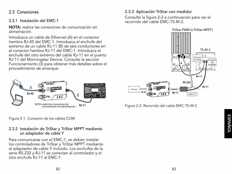
82 83
2.3.3 Aplicación TriStar con medidor Consulte la figura 2-2 a continuación para ver el recorrido del cable EMC-TS-M-2.
Figura 2-2. Recorrido del cable EMC-TS-M-2
TS-M-2
TriStar PWM (or TriStar MPPT)
RJ-11RJ-45
RJ-11
RJ-11
RS-232
Meter Jack
TriStar Jack
Y-cable
To Network
TS-M-2
TriStar PWM (o TriStar MPPT)
RJ-11RJ-45
RJ-11
RJ-11
RS-232
Conectordel
medidor
Conectorde TriStar
Cable en Y
A la red
ESPA
ÑO
L
2.3 Conexiones
2.3.1 Instalación del EMC-1
NOTA: realice las conexiones de comunicación sin alimentación.Introduzca un cable de Ethernet (A) en el conector hembra RJ-45 del EMC-1. Introduzca el enchufe del extremo de un cable RJ-11 (B) de seis conductores en el conector hembra RJ-11 del EMC-1. Introduzca el enchufe del otro extremo del cable RJ-11 en el puerto RJ-11 del Morningstar Device. Consulte la sección Funcionamiento (3) para obtener más detalles sobre el procedimiento de arranque.
Figura 2-1. Conexión de los cables COM
2.3.2 Instalación de TriStar y TriStar MPPT mediante un adaptador de cable Y
Para comunicarse con el EMC-1, se deben instalar los controladores de TriStar y TriStar MPPT mediante el adaptador de cable Y incluido. Los enchufes de la serie RS-232 y RJ-11 se conectan al controlador y el otro enchufe RJ-11 al EMC-1.
A
BRJ-45
RJ-11NOTA: realice las conexiones de comunicación sin alimentación.

84 85
2.5 Conexión de los cables de alimentaciónEl EMC-1 se alimenta con un suministro de 8-80 V CC, como un convertidor de CA-CC o una batería del sistema conectada a la entrada de alimentación suministrada en la unidad EMC-1. Consulte la sección Funcionamiento (3) para obtener más detalles sobre el procedimiento de arranque. Conecte los cables de alimentación como se indica en la figura 2-4 a continuación.
Figura 2-4. Conexión de los cables de alimentación
NOTA: si bien el Morningstar Device suministrará alimentación al EMC-1 a través del puerto Meterbus, quizás no sea suficiente en todas las condiciones de funcionamiento. Se requiere un suministro de alimentación de 8-80 V como fuente de energía constante y fiable.
CORRECTO
Fusible de 5 A ysoporte - 4 entradasdesde el terminalpositivo (+) de la batería.
NOTA: el EMC-1 se pondrá enmarcha mediante una conexiónRJ-11 a un Morningstar Deviceencendido o mediantealimentación directa al EMC.
ESPA
ÑO
L
2.4 Configuración del interruptor DIPEn la figura 2-3 se muestran las ubicaciones y funciones del interruptor DIP:
Figura 2-3. Funciones del interruptor DIP
2.4.1 Escrituras de Ethernet
Con el DIP 1 activado, las escrituras de Ethernet están activadas y los programas personalizados, las actualizaciones de firmware (al EMC-1) y la configuración de red se pueden escribir en un Morningstar Device. Si bien este interruptor DIP es una característica de seguridad diseñada para evitar cambios de configuración imprevistos del Morningstar Device, el DIP 1 no es un sustituto para lograr una seguridad de red correcta.
DIP 1 ACTIVADO(hacia arriba)- Permite las escriturasde Ethernet
DIP 2 - Uso futuro

86 87
SECUENCIA DE ARRANQUE DEL EMC-1 (con el Morningstar Device conectado)
Parpadeo del LED de estado V
LED encendidos durante 3 segundos V + V + (V)
Con el EMC-1 encendido y el cable RJ-45 conectado, los LED del RJ-45 se encenderán como se indica en la tabla siguiente.
INDICACIONES DEL CONECTOR HEMBRA DE ETHERNET
Condición LED verde LED amarillo
Conexión de red correcta Encendido Apagado
Actividad de red Encendido Parpadea
Error Apagado Encendido
3.3 LED de estado del EMC-1 (verde y rojo)
Verde intermitente: 1 vez por segundo - quizás no aparezca
si Morningstar Device se encuentra rápidamente
Se busca Morningstar Device
Verde fijo (señal de red apagada)
Se encontró Morningstar Device, comunicando
V-V-V....R-V-V-V… (se repite) No se han encontrado Morningstar Devices válidos
Rojo - verde intermitentes: 1 por segundo
Se encontró el Morningstar Device, ID de dispositivo
desconocida - actualización del firmware del EMC-1
ESPA
ÑO
L
3.0 FUNCIONAMIENTO
3.1 Indicadores LEDHay tres indicadores LED de EMC-1 (consulte la figura 3-1 a continuación) que indican todos los estados del EMC-1. De izquierda a derecha: LED de estado (verde/rojo). LED de servicio web (verde/rojo). LED de activación de escritura de Ethernet (verde).
Figura 3-1. Indicadores LED
3.2 Arranque
Una vez que se haya instalado el EMC-1, como se describe en la sección 2.3.1, la unidad se inicia con la conexión del suministro de alimentación, como se describe en la sección 2.5. En el arranque, el LED de estado parpadeará en verde una vez y, a continuación, todos los LED [verde, verde (verde)] se encenderán simultáneamente durante tres segundos. A continuación, el EMC-1 comenzará a buscar automáticamente los Morningstar Devices válidos. Si está instalado, el Morningstar Device debe tener el interruptor DIP de MODBUS habilitado para que se realice la conexión.
Estado del EMC-1 Estado del
servicio web
Estado de la escritura de Ethernet
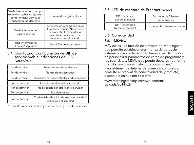
88 89
3.5 LED de escritura de Ethernet (verde)
DIP 1 apagado (verde apagado)
Escrituras de Ethernet desactivadas
DIP 1 encendido (verde encendido)
Escrituras de Ethernet activadas
3.6 Conectividad 3.6.1 MSViewMSView es una función de software de Morningstar que permite establecer una interfaz de datos del sistema con un ordenador en tiempo real, la función de personalizar parámetros de carga de programas y registrar datos. MSView se puede descargar de forma gratuita: www.morningstarcorp.com/msview/ Para obtener los detalles de conexión completos, consulte el Manual de conectividad del producto, disponible en nuestro sitio web:www.morningstarcorp.com/wp-content/uploads/2014/02/
ESPA
ÑO
L
Verde intermitente: 1 vez por segundo - quizás no aparezca
si Morningstar Device se encuentra rápidamente
Se busca Morningstar Device
Verde intermitente: 3 por segundo
Actualización o degradación de firmware en curso. No se debe
desconectar la alimentación mientras el dispositivo se encuentre en este estado.
Rojo intermitente: 1 cada 2 segundos Condición de error interno
3.4 (Uso futuro) Configuración de DIP de servicio web e indicaciones de LED (verde/rojo)
Por determinar Transmisiones desactivadas
Por determinar Transmisiones activadas
Por determinar Buscando servidor/estableciendo conexión
Por determinar Conexión realizada/transmitiendo
Por determinar No se puede conectar con el servidor
Por determinar Por determinar
Por determinarCredenciales de inicio de sesión no válidas*
(conectado al servidor)
* Error de inicio de sesión y/o error de registro del servidor

90 91
NOTA: muchas redes son compatibles con DHCP y la asignación de la dirección IP cambiará después de un cierto período. La dirección NetBIOS es un identificador estático del Morningstar Device y siempre señalará a tal Morningstar Device.
Después de la conexión al servidor de LiveView, se pueden visualizar las páginas web siguientes:
LiveViewEsta es la página web predeterminada, que muestra datos básicos del sistema, errores y alarmas en tiempo real.
RedEsta página web muestra la configuración de red actual del Morningstar Device y permite la opción de cambiar la configuración de comunicación y el enrutamiento de los puertos:
DHCP DNS primarioDirección IP Puerto 502 de IP de ModbusMáscara de subred ID de dispositivo predeterminado (MODBUS)Puerta de enlace HTTP puerto 80
Registro de datosEsta página web muestra el día actual y un cierto período de información del sistema histórica y detallada, según el número de variables establecidas para el registro.
SistemaLa página web del sistema se utiliza para actualizar el firmware del EMC-1. El firmware del dispositivo conectado no se puede actualizar a través de la página web del sistema. Esta página también muestra la información de diagnóstico específica del EMC-1.
ESPA
ÑO
L
La pestaña "Device" de MSView se puede utilizar para buscar los dispositivos conectados mediante la función "Search for Connected Devices". La pantalla de búsqueda mostrará el Morningstar Device, su n.º de serie de 8 dígitos y la dirección IP común del EMC-1/Morningstar Device. La dirección IP se puede utilizar para ver páginas web como se describe en la sección 3.6.2 a continuación. La dirección IP predeterminada de la unidad es 192.168.1.253
3.6.2 Páginas web de LiveViewMediante un navegador web, el EMC-1 permite acceder a las páginas web de LiveView de un Morningstar Device a través de dos métodos: 1) Escriba la dirección IP del Morningstar Device en la barra de direcciones, por ejemplo http://192.168.1.186.
2) Escriba un nombre NetBIOS del Morningstar Device [abreviatura del producto + n.º de serie de 8 dígitos] en la barra de direcciones, por ejemplo http://ssmppt15320850
Abreviaturas NetBIOS de productos
TriStar MPPT tsmppt
ProStar MPPT psmppt
ProStar Gen 3 pspwm
SunSaver MPPT ssmppt
TriStar PWM ts
SunSaver Duo ssduo
SureSine suresine
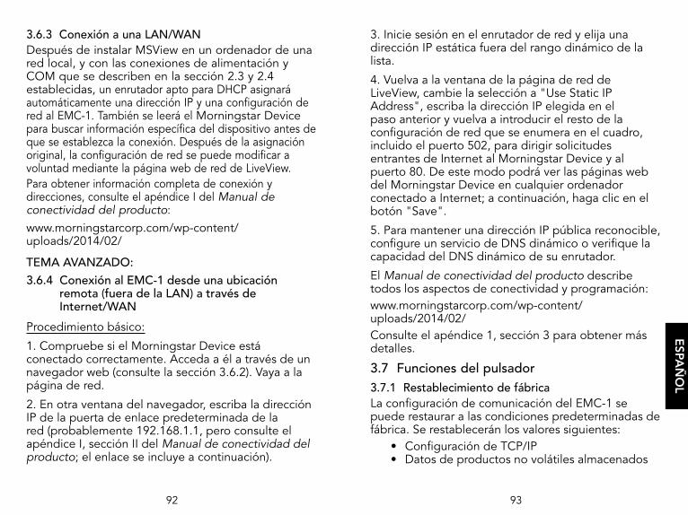
92 93
3. Inicie sesión en el enrutador de red y elija una dirección IP estática fuera del rango dinámico de la lista.
4. Vuelva a la ventana de la página de red de LiveView, cambie la selección a "Use Static IP Address", escriba la dirección IP elegida en el paso anterior y vuelva a introducir el resto de la configuración de red que se enumera en el cuadro, incluido el puerto 502, para dirigir solicitudes entrantes de Internet al Morningstar Device y al puerto 80. De este modo podrá ver las páginas web del Morningstar Device en cualquier ordenador conectado a Internet; a continuación, haga clic en el botón "Save".
5. Para mantener una dirección IP pública reconocible, configure un servicio de DNS dinámico o verifique la capacidad del DNS dinámico de su enrutador.
El Manual de conectividad del producto describe todos los aspectos de conectividad y programación: www.morningstarcorp.com/wp-content/uploads/2014/02/Consulte el apéndice 1, sección 3 para obtener más detalles.
3.7 Funciones del pulsador3.7.1 Restablecimiento de fábricaLa configuración de comunicación del EMC-1 se puede restaurar a las condiciones predeterminadas de fábrica. Se restablecerán los valores siguientes:
• Configuración de TCP/IP• Datos de productos no volátiles almacenados
ESPA
ÑO
L
3.6.3 Conexión a una LAN/WANDespués de instalar MSView en un ordenador de una red local, y con las conexiones de alimentación y COM que se describen en la sección 2.3 y 2.4 establecidas, un enrutador apto para DHCP asignará automáticamente una dirección IP y una configuración de red al EMC-1. También se leerá el Morningstar Device para buscar información específica del dispositivo antes de que se establezca la conexión. Después de la asignación original, la configuración de red se puede modificar a voluntad mediante la página web de red de LiveView. Para obtener información completa de conexión y direcciones, consulte el apéndice I del Manual de conectividad del producto: www.morningstarcorp.com/wp-content/uploads/2014/02/
TEMA AVANZADO:3.6.4 Conexión al EMC-1 desde una ubicación
remota (fuera de la LAN) a través de Internet/WAN
Procedimiento básico:
1. Compruebe si el Morningstar Device está conectado correctamente. Acceda a él a través de un navegador web (consulte la sección 3.6.2). Vaya a la página de red.
2. En otra ventana del navegador, escriba la dirección IP de la puerta de enlace predeterminada de la red (probablemente 192.168.1.1, pero consulte el apéndice I, sección II del Manual de conectividad del producto; el enlace se incluye a continuación).
94 95
4.0 SOLUCIÓN DE PROBLEMAS
4.1 Errores y correcciones
En la tabla 4.1 siguiente se muestran las principales condiciones de error del EMC-1:
V-V-V....R-V-V-V… (se repite)No se han encontrado
Morningstar Devices válidos
Rojo/verde intermitentes - 1 por segundo
Se ha encontrado un Morningstar Device, ID de dispositivo desconocido
Rojo intermitente - 1 cada 2 segundos Condición de error interno
Tabla 4.1. Condiciones de error
Problema:No se han encontrado Morningstar Devices válidos.
Soluciones:Utilice un cable RJ-11 para conectar el Morningstar Device al EMC-1.
Encienda el interruptor DIP MODBUS del Morningstar Device.
Problema:Se ha encontrado un Morningstar Device, ID de dispositivo desconocido.
Solución:Actualice el firmware del EMC-1 mediante la página web del sistema; consulte la sección 3.6.1.
ESPA
ÑO
L
Para realizar un restablecimiento de fábrica:1) Con el EMC-1 encendido, mantenga pulsado el botón de restablecimiento hasta que el LED de estado (a la izquierda) comience a parpadear en R-V, R-V.... 2) Suelte el botón de restablecimiento.3) El EMC-1 se reiniciará con la configuración de fábrica predeterminada.
3.7.2 Recuperación de un error de actualización de firmware
1) Con el EMC-1 apagado, mantenga pulsado el botón de restablecimiento. 2) Vuelva a conectar la alimentación y el LED de estado verde comenzará a parpadear tres veces por segundo. Suelte el botón de restablecimiento una vez que comience el parpadeo. 3) La degradación de recuperación está en curso, y cuando se complete, el EMC-1 dará servicio a la página web del sistema y permitirá que el usuario pueda volver a cargar el firmware más reciente.
96 97
5.0 GARANTÍA
GARANTÍA LIMITADA
Se garantiza que el EMC-1 no tiene defectos en los materiales ni en la calidad durante un período de CINCO (5) años a partir de la fecha de envío al usuario final original. Morningstar se encargará, a su criterio, de reparar o reemplazar cualquier unidad defectuosa.
EXCLUSIONES Y LIMITACIONES DE LA GARANTÍA:
Esta garantía no se aplicará en las siguientes condiciones:
♦ Daños por accidente, negligencia, abuso o uso incorrecto.
♦ Corrientes fotovoltaicas o de carga que superen la capacidad nominal del producto.
♦ Modificación o intento de reparación no autorizados del producto.
♦ Daños ocurridos durante el envío.
♦ Daños provocados por fenómenos naturales, como rayos, y fenómenos meteorológicos extremos.
LA GARANTÍA Y LOS RECURSOS ESTABLECIDOS ANTERIORMENTE SON DE CARÁCTER EXCLUSIVO Y SUSTITUYEN A TODOS LOS DEMÁS, DE MANERA EXPRESA O IMPLÍCITA. MORNINGSTAR RENUNCIA ESPECÍFICAMENTE A TODAS Y CADA UNA DE LAS GARANTÍAS IMPLÍCITAS, LO QUE INCLUYE, SIN LIMITACIÓN, LAS GARANTÍAS DE COMERCIABILIDAD E IDONEIDAD PARA UN PROPÓSITO PARTICULAR. NINGÚN DISTRIBUIDOR, AGENTE O EMPLEADO ESTÁ AUTORIZADO A REALIZAR UNA MODIFICACIÓN O EXTENSIÓN DE ESTA GARANTÍA.
MORNINGSTAR NO SE HARÁ RESPONSABLE DE LOS DAÑOS INCIDENTALES O DERIVADOS DE CUALQUIER TIPO QUE INCLUYAN, ENTRE OTROS, PÉRDIDA DE BENEFICIOS, TIEMPO DE INACTIVIDAD, FONDO DE COMERCIO O DAÑOS AL EQUIPO O A LA PROPIEDAD.
R17-8/16
ESPA
ÑO
L
Problema:Condición de error interno.
Solución:Comuníquese con el distribuidor de Morningstar para obtener asistencia.
Problema:
No es posible conectarse al controlador mediante Ethernet.
Soluciones:
Encienda el interruptor DIP MODBUS del Morningstar Device.
Confirme que el Morningstar Device esté encendido.
Compruebe el buen estado de los cables y las conexiones de Ethernet.
Compruebe que el nombre NetBIOS o la dirección IP se hayan escrito correctamente en la barra de direcciones del navegador web; puede resultar útil usar http:// en lugar de https://.
Para obtener los detalles de conexión completos, consulte el Manual de conectividad del producto, disponible en nuestro sitio web:
www.morningstarcorp.com/wp-content/uploads/2014/02/

98 99
6.0 ESPECIFICACIONES TÉCNICAS
Eléctricas:Intervalo de voltaje de suministro de entrada de CC 8-80 V CC
Autoconsumo ~2 W
Datos y comunicaciones:Puertos de comunicaciones MeterBus (RJ-11)
Ethernet (RJ-45)Protocolos de comunicación Morningstar MeterBus;
MODBUS TCP/IP; SNMPVelocidad de Ethernet 10/100 Base-T
Mecánicas:IP en interiores, IP20Carcasa de plásticoMontaje en riel DIN 35 mm estándarPeso (solo la unidad): 0,28 libras / 0,13 kg
Ambientales: Intervalo de temperatura de funcionamiento -40 ºC a +60 ºC
Temperatura de almacenamiento -55 ºC a 80 ºC
Humedad 100% sin condensación
7.0 CERTIFICACIONES
• Cumple con C-Tick RCM• Cumple con FCC clase B
Directivas EN:• Cumple con los estándares EN para marcas CE• Inmunidad: EN 61000-4-3: 2006 EN 61000- 4-6: 2009
• Emisiones: CISPR 22: 2008
EMC-1TM y MeterbusTM son marcas comerciales de Morningstar Corporation.
MODBUSTM y MODBUS TCP/IPTM son marcas comerciales de Modbus IDA. www.modbus-ida.org.
© 2020 Morningstar Corporation. Todos los derechos reservados.
MS-001796 v2.6
REACHALL
COMPONENTS
COMPLIANT
Registration, Evaluation andAuthorization of Chemicals
TUVRheinland®
CERTIFIED
ESPA
ÑO
L