installation and operation guide -...
TRANSCRIPT

www.vicon-security.com
Installation and Operation Guide
XX232-00-02
V662-D High-Resolution Analog WDR Camera
Vicon Industries Inc. does not warrant that the functions contained in this equipment will meet your requirements or that the operation will be entirely error free or perform precisely as described in the documentation. This system has not been designed to be used in life-critical situations and must not be used for this purpose.
Vicon Industries Inc., 89 Arkay Drive, Hauppauge, New York 11788Tel: 631-952-2288 Fax: 631-951-2288 Toll Free: 800-645-9116
24-Hour Technical Support: 800-34-VICON (800-348-4266) UK: 44/(0) 1489-566300
Document Number: 8009-8232-00-02 Product specifications subject to change without notice.
Issued: 513Copyright © 2013 Vicon Industries Inc. All rights reserved.
WARNINGTO REDUCE THE RISK OF FIRE OR ELECTRIC SHOCK, DO NOT EXPOSE THIS PRODUCT TO RAIN OR MOISTURE. DO NOT INSERT ANY METALLIC OBJECT THROUGH VENTILATION GRILLS.
CAUTIONRISK OF ELECTRIC SHOCK
DO NOT OPEN
WARNING : TO REDUCE THE RISK OF ELECTRIC SHOCK,DO NOT REMOVE COVER(OR BACK).
NO USER-SERVICABLE PARTS INSIDE. REFFER SERVICING TO QUALIFIED SERVICE PERSONNEL.
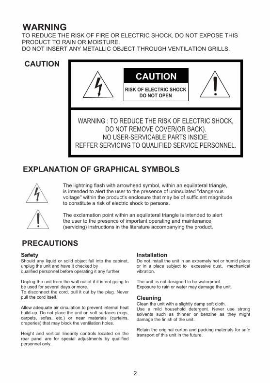
CAUTION EXPLANATION OF GRAPHICAL SYMBOLS The lightning flash with arrowhead symbol, within an equilateral triangle, is intended to alert the user to the presence of uninsulated ''dangerous voltage'' within the product's enclosure that may be of sufficient magnitude to constitute a risk of electric shock to persons. The exclamation point within an equilateral triangle is intended to alert the user to the presence of important operating and maintenance (servicing) instructions in the literature accompanying the product. PRECAUTIONS
Safety Should any liquid or solid object fall into the cabinet,unplug the unit and have it checked by qualified personnel before operating it any further. Unplug the unit from the wall outlet if it is not going to be used for several days or more. To disconnect the cord, pull it out by the plug. Neverpull the cord itself. Allow adequate air circulation to prevent internal heatbuild-up. Do not place the unit on soft surfaces (rugs,carpets, sofas, etc.) or near materials (curtains,draperies) that may block the ventilation holes. Height and vertical linearity controls located on therear panel are for special adjustments by qualifiedpersonnel only.
InstallationDo not install the unit in an extremely hot or humid place or in a place subject to excessive dust, mechanical vibration. The unit is not designed to be waterproof. Exposure to rain or water may damage the unit. Cleaning Clean the unit with a slightly damp soft cloth. Use a mild household detergent. Never use strong solvents such as thinner or benzine as they might damage the finish of the unit. Retain the original carton and packing materials for safe transport of this unit in the future.
2

FCC COMPLIANCE STATEMENT CE COMPLIANCE STATEMENT
INFORMATION TO THE USER: THIS EQUIPMENT HAS BEEN TESTED AND FOUND TO COMPLY WITH THE LIMITS FOR A CLASS A DIGITAL DEVICE, PURSUANT TO PART 15 OF THE FCC RULES. THESE LIMITS ARE DESIGNED TO PROVIDE REASONABLE PROTECTION AGAINST HARMFUL INTERFERENCE WHEN THE EQUIPMENT IS OPERATED IN A COMMERCIAL ENVIRONMENT. THIS EQUIPMENT GENERATES, USES, AND CAN RADIATE RADIO FREQUENCY ENERGY AND IF NOT INSTALLED AND USED IN ACCORDANCE WITH THE INSTRUCTION MANUAL, MAY CAUSE HARMFUL INTERFERENCE TO RADIO COMMUNICATIONS. OPERATION OF THIS EQUIPMENT IN A RESIDENTIAL AREA IS LIKELY TO CAUSE HARMFUL INTERFERENCE IN WHICH CASE THE USER WILL BE REQUIRED TO CORRECT THE INTERFERENCE AT HIS OWN EXPENSE.
CAUTION: CHANGES OR MODIFICATIONS NOT EXPRESSLY APPROVED BY THE PARTY RESPONSIBLE FOR COMPLIANCE COULD VOID THE USER'S AUTHORITY TO OPERATE THE EQUIPMENT.
THIS CLASS A DIGITAL APPARATUS COMPLIES WITH CANADIAN ICES-003. CET APPAREIL NUMÉRIQUE DE LA CLASSE A EST CONFORME À LA NORME NMB-003 DU CANADA.
WARNING: This is a Class A product. In a domestic environment this product may cause radio interference in which case the user may be required to take adequate measures.
3

4
IMPORTANT SAFEGUARDS
1. Read these instructions.
2. Keep these instructions.
3. Heed all warnings.
4. Follow all instructions.
5. Do not use this apparatus near water.
6. Clean only with dry cloth.
7. Do not block any ventilation openings. Install in accordance with the manufacturer’s instructions.
8. Do not install near any heat sources such as radiators, heat registers, stoves, or other apparatus (including amplifiers) that produce heat.
9. Do not defeat the safety purpose of the polarized or grounding-type plug. A polarized plug has two blades with one wider than the other. A grounding type plug has two blades and a third grounding prong. The wide blade or the third prong are provided for your safety. If the provided plug does not fit into your outlet, consultan electrician for replacement of the obsolete outlet.
10. Protect the power cord from being walked on or pinched particularly at plugs, convenience receptacles, and the point where they exit from the apparatus.
11. Only use attachments/accessories specified by the manufacturer.
12. Use only with the cart, stand, tripod, bracket, or table specified by the manufacturer, or sold with the apparatus. When a cart is used,
use caution when moving the cart/apparatus combination to avoid injury from tip-over.
13. Unplug this apparatus during lightning storms or when unused for
long periods of time. 14. Refer all servicing to qualified service personnel. Servicing is required when the
apparatus has been damaged in any way, such as power-supply cord or plug is damaged, liquid has been moisture, does not operate normally, or has been dropped.
15. CAUTION – THESE SERVICING INSTRUCTIONS ARE FOR USE BY QUALIFIED
SERVICE PERSONNEL ONLY. TO REDUCE THE RISK OF ELECTRIC SHOCK DO NOT PERFORM ANY SERVICING OTHER THAN THAT CONTAINED IN THEOPERATING INSTRUCTIONS UNLESS YOU QRE QUALIFIED TO DO SO.
16. Use Certified/Listed Class 2 power source only.
17. Apparatus shall not be exposed to dripping or splashing and no object filled with liquids, such as vases, shall be placed on the apparatus.
CONTENTS OF PACKAGE
Installation of the camera must be performed by qualified service personnel in accordance with all local and national electrical and mechanical codes.
Carefully remove the color camera and its accessories from the carton and verify that they were not damaged in shipment.
The content of the package includes:
1. Color CCD camera
2. Mini-DIN connector (for video-or dc-type auto-iris lens)
3. CS adapter ring for C mounting "C" lenses
TABLE OF CONTENTS
INTRODUCTION ---------------------------------------------------------------------------------------6
CAMERA OVERVIEW --------------------------------------------------------------------------------7
BACK FOCUS ADJUSTMENT----------------------------------------------------------------------8
THE DEFINITION OF TERMS ----------------------------------------------------------------------9
CAMERA ADJUSTMENT ----------------------------------------------------------------------------11
CONTROL AND CONNECTIONS / DAY&NIGHT I/O TERMINALS-----------------------18
LENS ------------------------------------------------------------------------------------------------------19
SPECIFICATIONS -------------------------------------------------------------------------------------20
5
INTRODUCTION
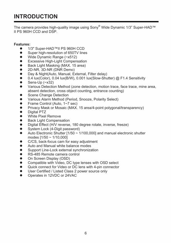
The camera provides high-quality image using Sony® Wide Dynamic 1/3” Super-HAD™ II PS 960H CCD and DSP.
Features: � 1/3" Super-HAD™II PS 960H CCD � Super high-resolution of 650TV lines � Wide Dynamic Range (~x512) � Excessive High-Light Compensation � Back Light Masking (MAX. 15 area) � 2D-NR, 3D-NR (DNR Demo) � Day & Night(Auto, Manual, External, Filter delay) � 0.4 lux(Color), 0.04 lux(B/W), 0.001 lux(Slow-Shutter) @ F1.4 Sensitivity � Sens-Up (~x32) � Various Detection Method (zone detection, motion trace, face trace, mine area,
absent detection, cross object counting, entrance counting) � Scene Change Detection � Various Alarm Method (Period, Snooze, Polarity Select) � Frame Control (Auto, 1~7 sec) � Privacy Mask or Mosaic (MAX. 15 area/4-point polygonal/transparency) � Digital PTZ � White Pixel Remove � Back Light Compensation � Digital Effect (H/V reverse, 180 degree rotate, inverse, freeze) � System Lock (4-Digit password) � Auto Electronic Shutter [1/50 ~ 1/100,000] and manual electronic shutter
modes [1/50 ~ 1/10,000] � C/CS, back-focus cam for easy adjustment � Auto and Manual white balance modes � Support Line-Lock external synchronization � RS-485 Remote camera control � On Screen Display (OSD) � Compatible with Video, DC type lenses with OSD select � Quick connect for Video or DC lens with 4-pin connector � User Certified / Listed Class 2 power source only � Operates in 12VDC or 24VAC
6

CAMERA OVERVIEW
SIDE VIEW
TOP VIEW
�
�� �
� �
�
�
FRONT VIEW
� Left Button � Up Button � Enter Button � Right Button � Down Button � Day/Night External I/O Motion ALARM OUT RS - 485 UTP(optional) � Power Indicator Video Output Connector (BNC) UTP or BNC Transformation Switch
(optional) � AC/DC Compatible Input Terminal
AC Power Cord
REAR VIEW
��
REAR VIEW (Free Voltage)
��
�
� �
7

BACK FOCUS ADJUSTMENT
When installing a zoom lens on a camera, sometimes the lens cannot be focused at either end of the zoom range. If this problem occurs, it may be necessary to adjust the camera back focus. By adjusting the back focus, the position of the pick-up device in relation to the rear of the lens is changing.
<PROCEDURE>
1. Secure the lens to the camera body, and plug in the auto iris connector.
2. Place a neutral density filter in front of the lens. This will force the lens iris to open to the max. (In the case of a manual lens, open the lens iris to its maximum.)
3. Set the focus of the lens to full infinity.
4. Set the zoom to Wide.
5. Aim the camera at a high contrast object a distance away and move the back-focus lever to bring object into focus.
6. Set the zoom to Tele.
7. Repeat the above steps until the focus remains clear throughout the zoom range.
Zoom
Focus
Back-focus lever
8

THE DEFINITION OF TERMS White Balance Compensates for deviations in the white color caused by changes in the color temperature of the light source so that the colors are reproduced correctly. Auto Exposure Automatically adjusts the images to the optimum brightness.
SHT(Electronic Shutter) Controls the integration time (exposure) of the photodiode array and reduces, blooming overexposure, and smear when capturing moving objects. Flicker(FLC) Avoids image flicker when there is a discrepancy between current and frequency
AGC(Automatic Gain Control) Automatically adjusts (boosts) the video signal to the required level to produce a quality image in low light situations Sens-Up(Slow Shutter) Allows the video sensor of a camera to control sensitivity as it automatically detects the light level in dark environments to maintain a clear picture. Back Light Compensation (BLC) Compensates for the brightness of the subjects with a large amount of background light that would make it practically impossible to see any details of the subjects. Adjusts the iris so that a distinctive subject and the background are delivered at the same time. Wide Dynamic Range (WDR) Extends the action of BLC. When both high-brightness subjects and low-brightness subjects are in the same scene, overexposure in the high-brightness subjects or loss of dark detail in the low-brightness subjects may occur. WDR combines the two images to eliminate over exposure and loss of detail.
EHLC(Excessive High Light Compensation) Brings excessively high-brightness subjects into focus.
MaskHides one or more areas that the user does not want to be displayed on screen. Masks can be set with their own display area, color, darkness and mosaic processing. Detection Detects motion within the scene using one of the available methods. Some methods trigger the Alarm output.
Sharpness Reducing this parameter adjusts the noise level to smooth out the "noise" caused by the compression. Caution should be taken not to reduce it too much, which may result in a blurred image.
9

Resolution Controls the display fine details. The higher the resolution, the higher level of details can be seen. 2D_ / 3D_NR (Digital Noise Reduction) Adjusts the illuminance noise level in low light situations by reducing image noise in order to improve the image. - 2D-NR is space-based and 3D-NR is time-based.
Frame Control Specifies how many frames are generated/transmitted in a unit of time. The more frames there are, the smoother the image will be, The television system(NTSC/PAL) has adopted 30/25 frames per second(fps) to be regarded as completely smooth image. However, when recording video data, video surveillance systems often use lower fram rates to reduce the size of the recording data.
NegaReverses the color signals for the Chroma signal so the image looks like a “negative.”
d-PTZ(Digital Pan/Tilt/Zoom) Adjusts the camera position and zooms in on a section of the overall full image. The pixels in this area are then enlarged so the image is the same size as the original, giving the appearance of being zoomed in. Widen the intervals between the pixels in the original signal according to the magnification, and then filing these intervals with interpolation signals.
Communication Allows for the connection to external devices, such as keyboards, through the menu interface. Iris Control Automatically adjusts the level of the iris according to changing light levels without having to manually turn a ring on the lens to open or close the iris. LLCIn the line lock mode, the AC power supply and vertical sync signal of the cameras are synchronized.
White Pixel Automatically detects and compensates for peak white levels to maintain the image quality. White pixels whose frequency of occurrence varies in proportion to the temperature are sometimes observed when the devices are used under the influence of external factors or especially high temperatures.
Day/Night Allows the camera to be effective even in the lowest of light conditions while still showing clear color pictures during daylight hours. Day/Night cameras automatically change from color images to black and white when the light levels drop below a certain level.
10

CAMERA ADJUSTMENT
<White Balance> 1) Auto(Auto White Balance) : AWB mode (1800ºK ~10500ºK) 2) Push/Hold : Push&Hold Mode.
To find the Optimal setting for the current luminance environment in this mode, set the direction towards a sheet of white paper and select Hold and press enter button. If the environment changes, readjust it.
3) CRS Mode(Color Rolling Suppression) : Decrease color rolling effect. This operation take some time about 10 seconds and user can stop this
operation by pressing enter button. When CRS Mode is on, color tone can be weak.
4) Outdoor : Set color temperature to outdoor (6300ºK) 5) Indoor : Set color temperature to indoor (3200ºK)6) FL(Fluorescent Light) : Set color temperature to fluorescent light fixed gain.7) User(User Set White Balance) : Adjust red or blue gain.
R(R-GAIN):Adjust R-GAIN value (0-255) B(B-GAIN):Adjust B-GAIN value (0-255)
<Auto Exposure> 1) SHT(s)(Electronic Shutter) : Select Shutter mode.
Auto(1/60(1/50) ~ 1/100,000 Auto run, Manual 8 step from 1/60(1/50) ~1/10,000). 2) FLC(Flicker-less) : Flicker-less On/Off. 3) AGC(Auto Gain Control) : AGC Gain(Off, Low, Middle, High) 4) Sens-Up(Slow Shutter) : Maximum Slow-Shutter select. (x2-x32 and Off) 5) Offset Add : Force the picture to turn up at low luminance environment. <BLC/WDR>1) Normal AE : BLC/WDR function off. 2) WDR(Wide Dynamic Range) : Wide dynamic range mode on. 3) EHLC(Excessive High Light Compensation) : EHLC mode on.
excessive lighting compensation is performed when the weighting on the high-brightness side is increased.
4) Auto(Auto Weighting BLC) : Auto weighting BLC on. 5) Spot(User Setting BLC area) : Spot metering mode on.
Posi : OSD mode to adjust the position of the spot metering area. Size : OSD mode to adjust the size of the spot metering area.
6) Zone(Preset BLC area) : Fixed metering area mode. (1-9).
<Mask>1) Mask: Select mask area(1-15). 2) Func: Select mask function.(Privacy, BLM, Both, Off).
Privacy : Area to screen on the display. BLM : Back Light Mask.
� Selected BL Mask area that will be except of the auto exposure � If there is a light mounted high in a closed environment such as an
apartment parking garage or gas station entrance, removing the high mounted light may make it possible to view car license plates clearly.
11

Both : Privacy function and BLM function on. Off : Function off.
3) Edit : Mask area edit. Edit mode take effect during Func not Off.
� Size : adjust the size of the Privacy and BLM mask area. � Posi : adjust the position of the Privacy and BLM mask area. � Tilt : adjust tilting of Privacy and BLM mask area. � Color: Select Privacy and BLM mask (0-14). � Transparency: Select Privacy mask transparency (Default 3/0-3). � Mosaic: Select Privacy and BLM mask mosaic On/Off � Adj. Mosaic: Adjust Privacy and BLM mask mosaic level (0-31).
<Detection>1) Func : Detection function selection.
OFF : Detection function off. Zone : Area motion detection mode.
� Zone : Select Motion detection zone (Zone1-4). � Func : Select Motion detection on/off. � Size : Press Enter button to adjust the size of the Motion detection area. � Posi : Press Enter button to adjust the position of the Motion detection
area. � Link Zoom : Select Motion detection with D-PTZ function that
On/Off.( When the motion triggered in the area, zoom and move to the area with D-PTZ.)
Motion Trace : Motion trace mode on. � Tracks an object through a scene and generates an alarm.
Face Trace : Face Trace mode on. � Tracks face through a scene and generate an alarm. � Sens Down : lower value is more widen the scope to judge face. (0~127) � Min Size : Minimum face size configuration (0 : minimum face size is to
none)
Depending upon overall conditions, Face Trace may produce inaccurate results..
Mine : By this function, User can draw motion detection area with free dotting � Set Mine : Press the Enter button to Set Mine mode.
< > : Move : Mine Zone move using the Left and Right buttons. UP:Set : Mine Zone setting using the Up button. DN:Clr : Mine Zone clear using the Down buttons. ENT:End : Press the Enter button to set Mine mode end.
� Clr All : Press the Enter button to set Mine area clear. � Display : Select Mine Display On/Off.
Absent : Press the Enter button to Absent detection mode. Detect object
appeared or removed the scene � Sens Down : Adjust sensitivity of Absent check(0-255).
12

Low luminance, object color and object size can affect accuracy.
Cross : Cross counting mode � Zone : Select Cross Zone using the Left and Right buttons (Zone 1, Zone
2). � Size : Adjust the size of the Cross zone. � Posi : Adjust the position of the Cross zone. � Direction : Select Cross Direction. � Alarm Cnt : Set alarm out cross count. Alarm count number is delaying
number before output alarm. � Reset Cnt : Cross count reset.
Fast moving objects will affect counting. Expand or decrease the detection zone area to compensate for this.
Long objects will affect counting accuracy. Expand or decrease the detection zone area to compensate for this.
Multiple objects passing through the detection zone will affect accuracy.
Entrance : Entrance counting mode. The object move in through the entrance, counting number increases � Size : Press Enter button adjust the size of the Entrance zone. � Posi : Press Enter button adjust the Position of the Entrance zone. � Alarm Cnt : Set alarm out entrance count. Alarm count number is
delaying number before output alarm. � Reset Cnt : Entrance count reset.
2) Sens Down : Adjust to Motion Sensitivity using left/right Buttons
Crossing objects are ignored. Multiple objects will not be detected.
If the distance is increases between the camera and entrance, the result may be inaccurate.
13
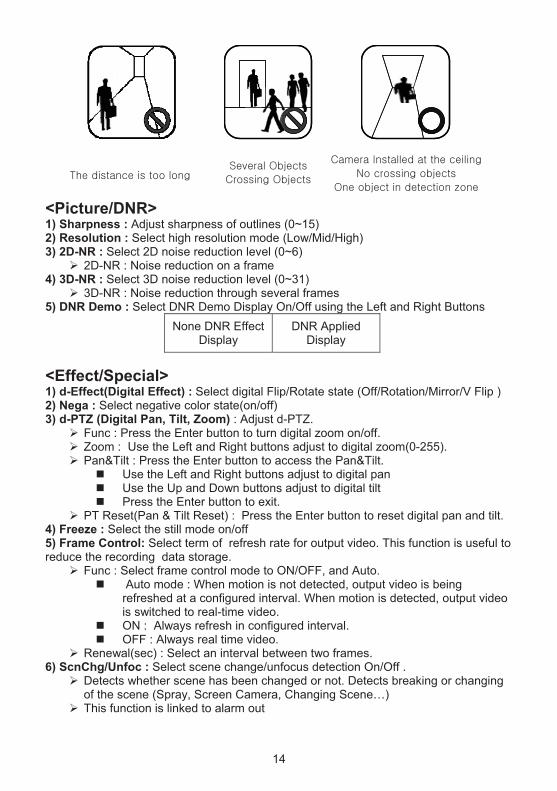
<Picture/DNR>1) Sharpness : Adjust sharpness of outlines (0~15) 2) Resolution : Select high resolution mode (Low/Mid/High) 3) 2D-NR : Select 2D noise reduction level (0~6)
2D-NR : Noise reduction on a frame 4) 3D-NR : Select 3D noise reduction level (0~31)
3D-NR : Noise reduction through several frames 5) DNR Demo : Select DNR Demo Display On/Off using the Left and Right Buttons
None DNR EffectDisplay
DNR Applied Display
<Effect/Special> 1) d-Effect(Digital Effect) : Select digital Flip/Rotate state (Off/Rotation/Mirror/V Flip ) 2) Nega : Select negative color state(on/off) 3) d-PTZ (Digital Pan, Tilt, Zoom) : Adjust d-PTZ.
Func : Press the Enter button to turn digital zoom on/off. Zoom : Use the Left and Right buttons adjust to digital zoom(0-255). Pan&Tilt : Press the Enter button to access the Pan&Tilt.
� Use the Left and Right buttons adjust to digital pan � Use the Up and Down buttons adjust to digital tilt � Press the Enter button to exit.
PT Reset(Pan & Tilt Reset) : Press the Enter button to reset digital pan and tilt. 4) Freeze : Select the still mode on/off 5) Frame Control: Select term of refresh rate for output video. This function is useful to reduce the recording data storage.
Func : Select frame control mode to ON/OFF, and Auto. � Auto mode : When motion is not detected, output video is being
refreshed at a configured interval. When motion is detected, output video is switched to real-time video.
� ON : Always refresh in configured interval. � OFF : Always real time video.
Renewal(sec) : Select an interval between two frames. 6) ScnChg/Unfoc : Select scene change/unfocus detection On/Off .
Detects whether scene has been changed or not. Detects breaking or changing of the scene (Spray, Screen Camera, Changing Scene…)
This function is linked to alarm out
14

Low luminance will affect accuracy.
In extremely low light environments or if there are moving objects, do not use this function.
<System Setup> 1) Cam Info : Camera basic information display
Cam ID/Baud rate/Protocol/Firmware Ver./CCD Type/Lens Type2) General Setup
System Lock : Configuration Lock. � When system lock is set to “Lock”, User must to input 4-character
password to enter OSD menu.
Default password is “0000”.
Change PID : Change the administrator’s password� Move cursor with OSD Key and Press Enter to input the character.
Comm(RS 485 Communication) : Press the Enter button to access the Comm.� Cam ID : Select the camera ID (001 - 255). � Baud Rate : Select serial communication speed (2400/4800/9600/19200). � Protocol : RS-485 protocol. (COMMAND/FASTRAX/PELCO-D/PELCO-P)
Title : Edit camera title.
Title Site_0
< > ENT:Del
Clear Cancel Accept
ABCDEFGHIJKLMNOPQRSTUVWXYZa b c d e f g h i j k l mn o p q r s t u v w x y z- . 0 1 2 3 4 5 6 7 8 9
C
D
A
B
A. Title
B. Delete character C. Character table D. Command line
- Clear : Clear Title - Cancel: Cancel editing - Accept: Save Title
Display : Display item select.� Cam ID : Camera ID display On/Off. � Title : Title display On/Off.
15

Alarm .
� Period : Alarm out period (5sec/10sec/20sec/30sec/1min/5min/Cont.)� Snooze : Alarm out snooze(Off/5sec/10sec/20sec/30sec/1min/5min)� Active pol : Alarm output active state configuration. (Low, High)
System Init � Cancel : Back to General Setup Menu. � Confirm : Initialize all data. (Factory Default)
3) Lens Iris : DC, Video, Manual Lens selected Iris : adjust AE Speed
� DC lens and video lens can adjust AE Speed Normal AE Ref (Auto Exposure Reference Level) : Press the Enter button to
access the AE Ref.� Ref Lvl : Adjust AE base reference level.
WDR Ref : Press the Enter button to access the WDR Ref. � Ref Lvl : Adjust the WDR long-time control Base Reference Level.
4) LLC(Line Lock Control) : Press the Enter button to access the Line Lock mode. Func : Select Line Lock function On/Off using the Left and Right buttons. Phase : Adjust Line Lock sync phase using the Left and Right buttons. (0~100)
Only activates when AC power is applied.
5) White Pixel Det Exe : Press Enter button to turn White Pixel Compensation mode Start.
� ENT to Adj : Press Enter button to start White Pixel Compensation start. � Proc : Process to find white pixel. � Done : Process ended
Det Count : Result of white pixel detection. Func : Select erasing white pixel function On/Off using the Left and Right buttons. Det Level : Select the judgment level of white pixel using the Left and Right
buttons (1~16) Det View : Select display of detected white pixel.
6) Day/Night Mode : Select D&N mode.
� Auto : Filter operates automatically according to brightness. � Day : The camera outputs the video image only in color. � Night : The camera outputs the video image only in black and white. � Ext : This menu automatically converts the COLOR Mode into the B/W
Mode or vice versa depending on illumination with an external sensor. Night Mode : Select B/W Burst On/Off Delay(s) : Adjust the working time of the filter when D&N mode is Auto (1-60 sec). D>N Level : Select switching level Day to Night when D&N mode is Auto (0-15).
16

N>D Level : Select switching level Night to Color when D&N mode is Auto (0-15).
<Bottom Line Menus> When user entered in main menu and sub-menus, following menus will be appeared.
I. Main Manu (menu in bottom lines) A. Exit : Save & Exit. B. Load : Load Default Value.
II. Sub Menu (menu in bottom lines) A. Return : Return to previous menu. B. Exit : Save & Exit
1) Exit Menu Save&Exit : Current environment values save. Exit : Disappear menu osd.
2) Load Default Setup Yes : Load default to current configuration. and return to previous menu. No : No operation, and return to previous menu.
17

CONTROL AND CONNECTIONS/DAY&NIGHT I/O / ALARM OUT TERMINALS
1 2 3 4 5 6 7 8 D&N I/O COM ALARM RS-485 UTP-
(optional) UTP+
(optional) IN OUT GND OUT RS-485+(RX) RS-485-(TX)
1) UTP Connections/Video output (optional) � 1 PIN: UTP- � 2 PIN: UTP+
2) DAY&NIGHT I/O Terminals To select Day/Night mode using external equipment, by connecting control lines to the appropriate terminals. � DAY&NIGHT OUTPUT (4pin)
Used to connect an external IR LED for additional illumination when Day/Night mode is set to AUTO. Controlled by AGC sensitivity.
� 5V/10mA : IR LED ON (NIGHT) � 0V : IR LED OFF (DAY)
4 DAY&NIGHT OUTPUT 5 COM
� DAY&NIGHT EXTERNAL INPUT (3pin)
Used to connect an external light sensor to the camera to provide an on/off signal, when Day/Night mode is set to External.
Open contact: DAY Close contact: NIGHT3 DAY&NIGHT INPUT
5 COM
3) ALARM OUT (6pin) - TTL level Motion detection signals are output through this port. Active state is configurable. 4) POWER INPUT TERMINAL
� This terminal accepts a DC12V or AC24V power source from a DC12V or AC24V ac +/-10% 60/50Hz +/- 1Hz. � Use Certified/Listed Class 2 power supply only. � It is recommended to use a DC power supply that can support
inrush current over 0.75A
CLASS 2 + DC 12V - ~ AC 24V ~
� AC Power Cord – The power cord accepts 100-240 VAC,
50/60HZ
5) CAMERA CONTROL � 7 PIN: RS 485+ � 8 PIN: RS 485-
18

LENSThe lens is not supplied with this camera. Purchase a lens suitable for your requirements. These cameras accept both C-and CS-mount type lens.
<Notes > � For using main functions it is recommended to use Auto Iris Lens with DC
type. � If the lens is marked with fingerprints other marks, the image quality might
be poor. � It is recommended to use a high quality lens to improve the image quality
under low illumination.
<INSTALLING AUTO IRIS LENS> 1. Remove the cover from the iris lens plug supplied, and solder the lens cable to the
plug as shown below.
� DC type: Pin 1 --- Damping- Pin 2 --- Damping+ Pin 3 --- Drive+ Pin 4 --- Drive-
Iris Control Cable
Automatic Iris Lens
Heat
ConnectorCover
ShrinkableTubes
Connector
2. Remove the protective cap, and attach the lens to the camera by turning clockwise.
19

SPECIFICATIONS
MODEL V662-D V662-D-P V662-D-PM Image sensor 1/3" Super-HADTM II PS 960H CCD Total pixels 1028(H)x508(V) 1028(H)x596(V) Effective pixels 976(H)x494(V) 976(H)x582(v) Scanning system 2:1 interlace Scanning frequency 15.734KHz(H)x5
9.94Hz(V) 15.625KHz(H)x50Hz(V)
Sync. System Internal / Line lock Resolution 650TVL Min. illumination 0.4 Lux (COLOR), 0.04 Lux (B/W), 0.001 Lux (Slow-shutter) Video output 1.0 Vp-p (75 ohm, composite) S/N ratio 50dB (AGC OFF)
G E N E R A L
Camera control RS485, compatible with Faxtrax, Pelco D, Pelco P White Balance Auto / CRS / Push&Hold / Indoor / Outdoor / FL / User Auto Exposure Auto / Manual Shutter / Flickerless / Low Light Control /
Offset Add AGC Off / Low / Middle / High Shutter Speed 1/60-1/10,000
(Auto:1/100,000)1/50-1/10,000 (Auto:1/100,000)
BLC EHLC / AUTO / SPOT / ZONE/ BLM Camera Title Alpha Numeric Display On / Off (Cam ID, Title) DNR 2DNR, 3D NR :Gain Adjust, DNR Demo Day & Night Auto / Day / Night / Ext Video Analytics Zone / Motion trace/ Face trace/ Minefield/ Absent / Cross /
Entrance/ Scene Change Detection Privacy zone Max 15 (Tilt, Color, Transparency, Mosaic) Effect V-Flip / Mirror / Rotation / Nega&Posi / Freeze / Sharpness Sense-up x32 Sharpness 0~15 steps Cam ID 001~255 WDR WDR: x512 (Level Adjust) D-Zoom ~ x256(D-Zoom) / D-PTZ Support Bad Pixel Adj/Done (Max 64 point), Detected pixel display System Lock Lock/Unlock (need Password input when Locked) Frame Control Auto, Off ~ 7Sec( Use for saving storage)
F U N C T I O N Other Function Admin Password, Alarm Setting(Period, Snooze, Polarity)
Power source DC 12V / AC 24V ± 10% 100-240V ~50Hz±1Hz
Power consumption 4.5 Watts
Power
Power input Terminal block Video output BNC, UTP (optional) Lens mount C/CS mount Auto iris output 4-Pin mini din jack (standard connection) Operating Temp. -10ºC to +50ºC Operating humidity Less than 90%
E T C
External dimension 78.8 (W) x 64 (H) x 118.4 (D)mm/Weight : 260g
78.8 (W) x 64 (H) x 118.4 (D)mm
/ Weight : 450g
20

Vicon Standard Equipment Warranty Vicon Industries Inc. (the “Company”) warrants your equipment to be free from defects in material and workmanship under Normal Use from the date of original retail purchase for a period of three years, with the following exceptions:
1. VCRs, all models: Labor and video heads warranted for 120 days from date of original retail purchase. All other parts warranted for one year from date of original retail purchase.
2. LCD and CRT monitors, all models: One year from date of original retail purchase. 3. Uninterruptible Power Supplies: Two years from date of original retail purchase. 4. VDR-700 Recorder Series: One year from date of original retail purchase. 5. V5616MUX: One year from date of original retail purchase. 6. Arecont Cameras: One year from date of original retail purchase. 7. FMC series fiber-optic media converters and associated accessories: Lifetime warranty. 8. For PTZ cameras, “Normal Use” excludes prolonged use of lens and pan-and-tilt motors, gear
heads, and gears due to continuous use of “autopan” or “tour” modes of operation. Such continuous operation is outside the scope of this warranty.
9. Vicon Security Management Systems (SMS) All Models: All hardware is warranted for two years from date of original retail purchase.
10. Any product sold as “special” or not listed in Vicon’s commercial price list: One year from date of original retail purchase.
Date of retail purchase is the date original end-user takes possession of the equipment, or, at the sole discretion of the Company, the date the equipment first becomes operational by the original end-user. The sole remedy under this Warranty is that defective equipment be repaired or (at the Company’s option) replaced, at Company repair centers, provided the equipment has been authorized for return by the Company, and the return shipment is prepaid in accordance with policy. The Company will not be obligated to repair or replace equipment showing abuse or damage, or to parts which in the judgment of the Company are not defective, or any equipment which may have been tampered with, altered, misused, or been subject to unauthorized repair. Software supplied either separately or in hardware is furnished on an “As Is” basis. Vicon does not warrant that such software shall be error (bug) free. Software support via telephone, if provided at no cost, may be discontinued at any time without notice at Vicon’s sole discretion. Vicon reserves the right to make changes to its software in any of its products at any time and without notice. This Warranty is in lieu of all other conditions and warranties express or implied as to the Goods, including any warranty of merchantability or fitness and the remedy specified in this Warranty is in lieu of all other remedies available to the Purchaser. No one is authorized to assume any liability on behalf of the Company, or impose any obligations on it in connection with the sale of any Goods, other than that which is specified above. In no event will the Company be liable for indirect, special, incidental, consequential, or other damages, whether arising from interrupted equipment operation, loss of data, replacement of equipment or software, costs or repairs undertaken by the Purchaser, or other causes. This warranty applies to all sales made by the Company or its dealers and shall be governed by the laws of New York State without regard to its conflict of laws principles. This Warranty shall be enforceable against the Company only in the courts located in the State of New York. The form of this Warranty is effective March 1, 2011. THE TERMS OF THIS WARRANTY APPLY ONLY TO SALES MADE WHILE THIS WARRANTY IS IN EFFECT. THIS WARRANTY SHALL BE OF NO EFFECT IF AT THE TIME OF SALE A DIFFERENT WARRANTY IS POSTED ON THE COMPANY’S WEBSITE, WWW.VICON-SECURITY.COM. IN THAT EVENT, THE TERMS OF THE POSTED WARRANTY SHALL APPLY EXCLUSIVELY. Vicon Part Number: 8006-9010-03-09 Rev 0311

Vicon Industries Inc.
Corporate Headquarters 89 Arkay Drive
Hauppauge, New York 11788 631-952-CCTV (2288) 800-645-9116
Fax: 631-951-CCTV (2288)
Vicon Europe Headquarters
Brunel Way Fareham, PO15 5TX
United Kingdom +44 (0) 1489 566300
Fax: +44 (0) 1489 566322
Vicon Germany Kornstieg 3
D-24537 Neumuenster Phone: +49 (0) 4321 8790 Fax: +49 (0) 4321 879 97
Far East Office Unit 5, 17/F, Metropole Square
2 On Yiu Street, Shatin New Territories,
Hong Kong (852) 2145-7118
Fax: (852) 2145-7117
Internet Address: www.vicon-security.com