installation and operating instructions intelligent … and operating instructions intelligent...
TRANSCRIPT
DS 400 mobile V1.29 Seite 1 von 109
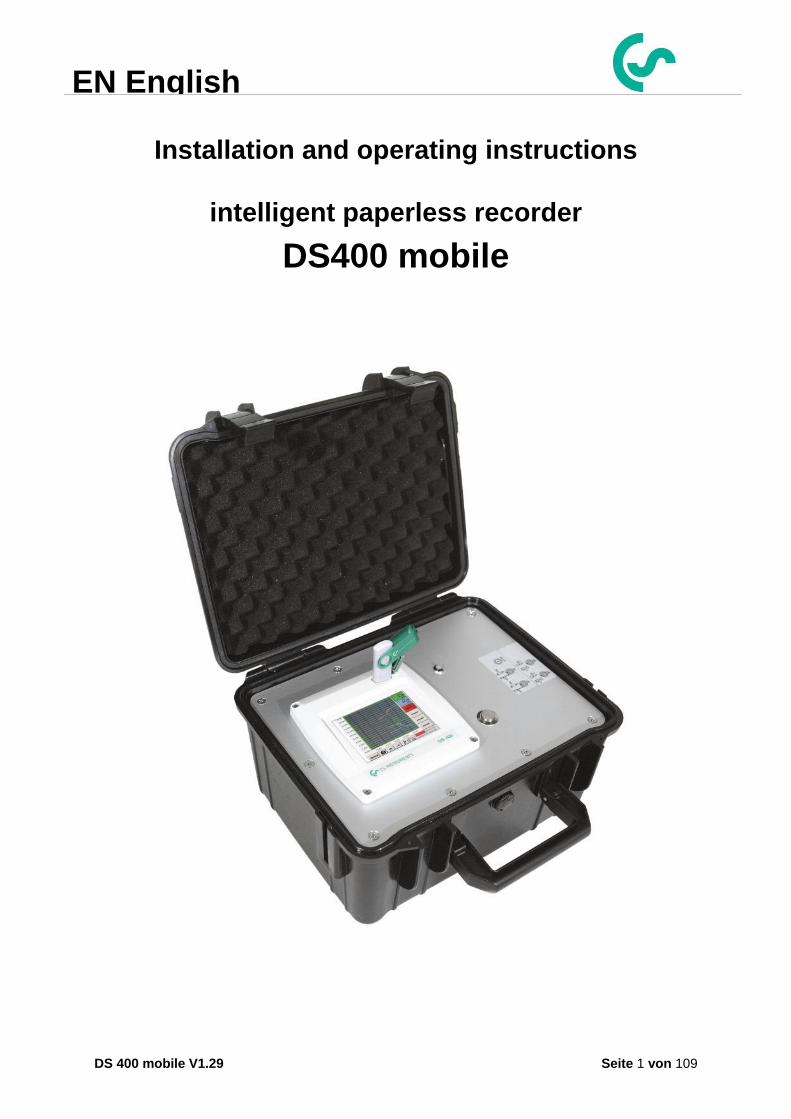
Installation and operating instructions
intelligent paperless recorder
DS400 mobile
EN English

Foreword
DS 400 mobile V1.29 Seite 2 von 109
I. Foreword
Dear customer,
thank you very much for deciding in favour of the DS 400. Please read this installation and operation manual carefully before mounting and initiating the device and follow our advice. A riskless operation and a correct functioning of the DS 400 are only guaranteed in case of careful observation of the described instructions and notes
Sales Office South / Geschäftsstelle Süd
Zindelsteiner Str. 15 D-78052 VS-Tannheim
Tel.: +49 (0) 7705 978 99 0 Fax: +49 (0) 7705 978 99 20
Mail: [email protected] Web: http://www.cs-instruments.com
Sales Office North / Geschäftsstelle Nord
Am Oxer 28c D-24955 Harrislee
Tel.: +49 (0) 461 700 20 25 Fax: +49 (0) 461 700 20 26
Mail: [email protected] Web: http://www.cs-instruments.com
Table of Contents
DS 400 mobile V1.29 Seite 3 von 109
II. Table of Contents
I. Foreword .................................................................... Fehler! Textmarke nicht definiert.
II. Table of Contents ......................................................................................................... 3
1 Safety instructions .......................................................................................................... 6
1.1 Generell ................................................................................................................................... 6
1.2 Installation .............................................................................................................................. 7
1.3 Lithium Ion Battery ................................................................................................................ 7
2 Application area ............................................................................................................... 8
3 Intended use ..................................................................................................................... 9
4 Technical data DS 400 ................................................................................................... 10
5 Input signal ..................................................................................................................... 11
6 Cable cross-section ....................................................................................................... 11
6.1 Sensor circuit points/Output signal ................................................................................... 11
7 Connection diagrams of the different sensor types ................................................... 12
7.1 Connector pin assignment for all sensors A1 – A2, B1 – B2 .......................................... 12
7.2 Connection diagrams .......................................................................................................... 13 7.2.1 Anschluss CS Taupunktsensoren Serie FA 415/FA 300 ................................................. 13 7.2.2 Connection for dew point- and consumption sensors, serial FA/VA 400 ........................ 13 7.2.3 Connection for dew point- and consumption sensors, series FA/VA 5xx ........................ 13 7.2.4 Connection pulse Sensors ............................................................................................... 14 7.2.5 Analogue two-, three-, and four-wire current signal ......................................................... 15 7.2.6 Three- and four-wire power supply 0 - 1/10/30 VDC ....................................................... 16 7.2.7 Two-, three- and four-wire connector pin assignments for PT100/PT1000/KTY81 ........ 17
7.3 Connection with RS485 ....................................................................................................... 17
8 Connect the DS 400 with a PC ...................................................................................... 18
Table of contents
DS 400 mobile V1.29 Seite 4 von 109
9 Operation DS 400 ........................................................................................................... 19
9.1 Switching on / off of the DS400 mobile .............................................................................. 19
9.2 Main menu (Home) ............................................................................................................... 19 9.2.1 Initialization ...................................................................................................................... 19 9.2.2 Main menu after initialization ........................................................................................... 20
9.3 Settings ................................................................................................................................. 21 9.3.1 Password-Settings ........................................................................................................... 21 9.3.2 Sensor-Settings ............................................................................................................... 22
9.3.2.1 Choice of the sensor type (For example type CS-Digital sensor) ............................ 23 9.3.2.2 Name the measurement data and define the decimal places .................................. 24 9.3.2.3 Recording measurement data .................................................................................. 24 9.3.2.4 Alarm-Settings .......................................................................................................... 25 9.3.2.5 More Settings (scale analogue output) ..................................................................... 27 9.3.2.6 Dew Point Sensor FA 400 / FA 410 of type CS-Digital (SDI Bus) ............................ 28 9.3.2.7 Flow sensor VA 400 / VA 420 of type CS-Digital (SDI Bus) ..................................... 29 9.3.2.8 Dew Point Sensor FA 500 / FA 510 of type FA 5xx (RS 485 Modbus) .................... 32
9.3.2.8.1 Settings Dew point sensor FA 500 FA 510 .......................................................... 33 9.3.2.8.1.1 Unit selection for temperature and humidity ................................................... 33
9.3.2.8.2 Definition of the System pressure (relative pressure value) ................................. 33 9.3.2.8.3 Definition of Reference pressure (absolute pressure value) ............................... 34 9.3.2.8.4 Calibration ............................................................................................................ 35 9.3.2.8.5 More Settings Analogue output 4-20mA ............................................................ 35
9.3.2.9 Flow sensor of type VA 5xx (RS 485 Modbus) ......................................................... 36 9.3.2.9.1 Settings for Flow sensor VA 5xx .......................................................................... 37
9.3.2.9.1.1 Diameter settings ........................................................................................... 37 9.3.2.9.1.2 Gas Constant settings .................................................................................... 38 9.3.2.9.1.3 Definition of the reference conditions ............................................................. 39 9.3.2.9.1.4 Definition Unit of flow and velocity ................................................................. 39 9.3.2.9.1.5 Definition consumption counter value and consumption unit ......................... 40
9.3.2.9.2 Settings analogue output 4-20mA of VA 5xx ........................................................ 41 9.3.2.9.3 Settings Pulse / Alarm output of VA 5xx ............................................................... 42 9.3.2.9.4 Settings ZeroPoint or Low Flow Cut off for VA 5xx .............................................. 44
9.3.2.10 Configuration of Analogue-Sensors ......................................................................... 45 9.3.2.10.1 Type 0 - 1/10/30 Volt und 0/4 – 20 mA ................................................................. 45 9.3.2.10.2 Type PT100x and KTY81 ..................................................................................... 47 9.3.2.10.3 Type Pulse (Pulse ration) ..................................................................................... 48 9.3.2.10.4 Type „No Sensor“ ................................................................................................. 50
9.3.2.11 Type Modbus ............................................................................................................ 51 9.3.2.11.1 Selection and activation of Sensor-Type Modbus ................................................ 51 9.3.2.11.2 Modbus Settings ................................................................................................... 51
9.3.2.12 Custom Sensor ......................................................................................................... 55 9.3.2.12.1 Sensor settings saving ......................................................................................... 55 9.3.2.12.2 Sensor settings import .......................................................................................... 56
9.3.3 Device Settings ................................................................................................................ 57 9.3.3.1 Language .................................................................................................................. 57 9.3.3.2 Date & Time .............................................................................................................. 58 9.3.3.3 Network-Settings ...................................................................................................... 59 9.3.3.4 Relay Settings .......................................................................................................... 60 9.3.3.5 SD-Card .................................................................................................................... 61 9.3.3.6 System ...................................................................................................................... 62
9.3.3.6.1 Save system settings ............................................................................................ 62 9.3.3.6.2 System update ...................................................................................................... 63 9.3.3.6.3 Check for Updates ................................................................................................ 63 9.3.3.6.4 Update Firmware .................................................................................................. 64 9.3.3.6.5 Update Channels .................................................................................................. 64 9.3.3.6.6 Factory Reset ....................................................................................................... 65
9.3.3.7 Calibrate touch-screen ............................................................................................. 66

Table of contents
DS 400 mobile V1.29 Seite 5 von 109
9.3.4 Set backlight .................................................................................................................... 66 9.3.5 Cleaning ........................................................................................................................... 67 9.3.6 System-Status .................................................................................................................. 67 9.3.7 About DS 400................................................................................................................... 67 9.3.8 Virtual Channels (optional) .............................................................................................. 68
9.3.8.1 Option „Virtual Channels“ activation ......................................................................... 68 9.3.8.2 Virtual Channels Einstellung..................................................................................... 69 9.3.8.3 Selection of Sensor-type .......................................................................................... 69 9.3.8.4 Configuration of each single virtual value ................................................................. 70
9.3.8.4.1 Activation of a single virtual value ........................................................................ 70 9.3.8.4.2 Definition of Operands .......................................................................................... 71 9.3.8.4.3 Definition of Operations ........................................................................................ 72 9.3.8.4.4 Definition of Unit ................................................................................................... 72
9.3.8.5 Value name, resolution of decimal places and recording of values ......................... 74 9.3.8.6 Calculation Example „Specific Performance“ .......................................................... 75
9.3.9 Analog Total (optional) ..................................................................................................... 77 9.3.9.1 Option „Analog Total“ activation ............................................................................... 77 9.3.9.2 Selection of sensor type ........................................................................................... 78
9.3.10 Webserver (optional) ....................................................................................................... 79 9.3.10.1 Option „Webserver“ activation .................................................................................. 79 9.3.10.2 Setup the Webserver Admin Password .................................................................... 80 9.3.10.3 Webserver start ........................................................................................................ 80 9.3.10.4 Webserver assignment of rights (Administrator) ...................................................... 81
9.3.10.4.1 Accessrights Webserver ....................................................................................... 81 9.3.10.5 Webserver Login ...................................................................................................... 81 9.3.10.6 New users and password ......................................................................................... 82 9.3.10.7 Webserver E-Mail Configuration (Administrator) ...................................................... 83 9.3.10.8 Webserver MailOnAlarm (Administrator & Operator) ............................................... 84 9.3.10.9 Webserver Chart (Administrator, Operator & User) ................................................. 85 9.3.10.10 Webserver Screen ................................................................................................... 86 9.3.10.11 Webserver Actuals .................................................................................................. 87 9.3.10.12 Webserver Status .................................................................................................... 87
9.3.11 Data Logger (optional) ..................................................................................................... 88 9.3.11.1 Option „Data Logger“ activation................................................................................ 88 9.3.11.2 Data logger Settings ................................................................................................. 88
9.4 Chart ...................................................................................................................................... 92
9.5 Chart / Real time values ....................................................................................................... 96
9.6 Channels ............................................................................................................................... 98
9.7 Real time values ................................................................................................................... 99
9.8 Alarm-Overview .................................................................................................................. 100
9.9 Export /Import ..................................................................................................................... 101 9.9.1 Eport Logger data .......................................................................................................... 101 9.9.2 Export System Settings ................................................................................................. 103 9.9.3 Import System Settings .................................................................................................. 104
9.10 Screenshot function .......................................................................................................... 105 9.10.1 Screenshot saving ......................................................................................................... 105 9.10.2 Screenshots export ........................................................................................................ 106
10 Cleaning .................................................................................................................... 108

Safety instructions
DS 400 mobile V1.29 Seite 6 von 109
1 Safety instructions
1.1 Generell
Please check whether this manual corresponds with the device type.
Please attend to all notes indicated in this instruction manual. It contains essential information that has to be followed during installation, operation and maintenance. Therefore, this instruction manual has to be read categorically by the technician as well as by the responsible user/qualified personnel before installation, initiation and maintenance.
This instruction manual has to be available at any time at the operation site of the DS 400.
Regional and national regulations respectively, have to be observed in addition to this instruction manual if necessary.
In case of any obscurities or questions with regard to this manual or the instrument please contact CS Instruments GmbH.
Warning!
Supply voltage!
Contact with supply voltage carrying non-insulated parts may cause an electric shock with injury and death.
Measures:
• Note all applicable regulations for electrical installations (e.g. VDE 0100)!
• Carry out maintenance only in strain less state!
• All electric works are only allowed to be carried out by authorized qualified personnel.
Warning!
Inadmissible operating parameters!
Undercutting and exceeding respectively of limit values may cause danger to persons and material and may lead to functional and operational disturbances.
Measures:
• Make sure that the DS 500 is only operated within the admissible limit values indicated on the type label.
• Strict observance of the performance data of the DS 400 in connection with the application.
• Do not exceed the admissible storage and transportation temperature.
Further safety instructions:
• Attention should also be paid to the applicable national regulations and safety instructions during installation and operation.
• The DS 400 is not allowed to be used in explosive areas.
Additional remarks:
• Do not overheat the instrument!
• Change of battery and SD-Card are only allowed to be carried out by authorized qualified personnel and in strain less state
Attention!
Malfunctions at the DS 400!
Faulty installation and insufficient maintenance may lead to malfunctions of the DS 400 which may affect the measuring results and which may lead to misinterpretations.
Safety instructions
DS 400 mobile V1.29 Seite 7 von 109
1.2 Installation
NOTE! The plug of the power supply unit (charger) is used as a separator.
This separator must be clearly recognisable and easily accessible by the user. A plug connector with a CEE7/7 system is necessary.
NOTE!
Only the supplied power supply may be used.
1.3 Lithium Ion Battery
Warning!
Battery!
The replacement of the battery must only be carried out by authorised and skilled personnel, and when the device is de-energised.
Only the original battery of the manufacturer with built-in protection circuit may be used
Do not use any other power supply for charging the Li-Ion battery as the provided.
Do not charge the battery under conditions that are not specified in the manual.
Do not charge the battery in an environment with flammable substances. Never charge the battery unattended.
Transport The contained lithium ion batteries are subject to the Dangerous Goods Legislation requirements. The user can transport the batteries by road without further requirements. When being transported by third parties (e.g.: air transport or forwarding agency), special requirements on packaging and labelling must be observed. For preparation of the item being shipped, consulting an expert for hazardous material is required. Please also observe possibly more detailed national regulations.
Disposal The datalogger, rechargeable batteries, accessories and packaging should be sorted for environmental friendly recycling. Do not dispose of power tools and batteries/rechargeable batteries into household waste!
Only for EC countries: According to the European Guideline 2012/19/EU, power tools that are no longer usable, and according to the European Guideline 2006/66/EC, defective or used battery packs/batteries, must be collected separately and disposed of in an environmentally correct manner. Batteries no longer suitable for use can be directly returned at:
CS Instruments GmbH Zindelsteiner Str. 15 D-78052 VS-Tannheim CS Instruments GmbH Am Oxer 28c D-24955 Harrislee

Application area
DS 400 mobile V1.29 Seite 8 von 109
2 Application area
Our long-term hands-on experience in measurement and control technology was implemented in the new DS 400.
From recording of the measured data, automatic sensor identification, indication on a big colour screen, alerting, storage up to remote read-out via web server, all that is possible with DS 400. By means of the CS-Soft, software alarms can be sent via SMS or e-mail.
On the big 3.5' colour screen with touch panel all information is available at a glance. The operation is very easy. All measured values, measured curves and threshold exceeding’s are indicated. The progression of the curve, since the beginning of the measurement, can be viewed by an easy slide of the finger. The huge difference to ordinary paperless chart recorders reveals in the easy initiation as well as in the evaluation of the measured data. All sensors are identified directly and powered by DS 400. Everything is matched and tuned.
Consumption sensor VA400 Clamp on
Ammeter
Consumtion counter VA420
Dew Point sensor FA410
Pressure sensor
Screw-in temperature Probe Pt1000
Temperature Probe Pt 100
Third Party
sensors
4… 20mA
Third Party
Sensors
RS485
Modbus RTU
Third Party
sensors
Electricity
meter KWh
Third Party
sensors
Pulse
Third Party
sensors
0...1V/10V
Netzteil230VAC / 12VDC
Versatile: Up to 4 sensors, incl. all CS sensors
(consumption, dew point, pressure,
current, KTY, PT 100, PT 1000) are
identified automatically by DS 400.
Optional analogue sensors (0/4 - 20
mA, 0 - 1/10/30 V, pulse) can be
configured easily and quickly. Digital
sensors can be connected via RS 485, Modbus RTU and SDI.
Flexible: Network-compatible and worldwide remote data transmission via Ethernet, integrated web server.
Alarm relay / fault indication: Up to 4 threshold values can be configured freely. Collective alarms are possible. Remark: Alarm relays are available with DS400, not accessible at DS 400 mobile.
Intended use
DS 400 mobile V1.29 Seite 9 von 109
3 Intended use
The DS 400 data logger serves for the stationary measured data acquisition and storage of analogue and digital input signals.
The DS 400 data logger is exclusively designed and constructed for the proper application purpose that is described herein and must only be used correspondingly.
A check in order to ascertain whether or not the device is suitable for the chosen employment must be carried out by the user. It must be ensured that the medium is compatible with the components which come into contact with it. The technical data listed in the data sheet are binding.
Improper handling or operation outside the technical specifications is impermissible. Claims of any kind on the basis of improper use are excluded.
Technical data DS 400
DS 400 mobile V1.29 Seite 10 von 109
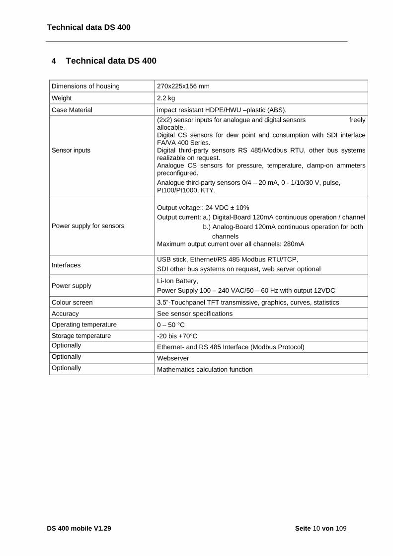
4 Technical data DS 400
Dimensions of housing 270x225x156 mm
Weight 2.2 kg
Case Material impact resistant HDPE/HWU –plastic (ABS).
Sensor inputs
(2x2) sensor inputs for analogue and digital sensors freely allocable. Digital CS sensors for dew point and consumption with SDI interface FA/VA 400 Series. Digital third-party sensors RS 485/Modbus RTU, other bus systems realizable on request. Analogue CS sensors for pressure, temperature, clamp-on ammeters preconfigured.
Analogue third-party sensors 0/4 – 20 mA, 0 - 1/10/30 V, pulse, Pt100/Pt1000, KTY.
Power supply for sensors
Output voltage:: 24 VDC ± 10%
Output current: a.) Digital-Board 120mA continuous operation / channel
b.) Analog-Board 120mA continuous operation for both
channels Maximum output current over all channels: 280mA
Interfaces USB stick, Ethernet/RS 485 Modbus RTU/TCP,
SDI other bus systems on request, web server optional
Power supply Li-Ion Battery,
Power Supply 100 – 240 VAC/50 – 60 Hz with output 12VDC
Colour screen 3.5“-Touchpanel TFT transmissive, graphics, curves, statistics
Accuracy See sensor specifications
Operating temperature 0 – 50 °C
Storage temperature -20 bis +70°C
Optionally Ethernet- and RS 485 Interface (Modbus Protocol)
Optionally Webserver
Optionally Mathematics calculation function

Input Signal
DS 400 mobile V1.29 Seite 11 von 109
5 Input signal
6 Cable cross-section
6.1 Sensor circuit points/Output signal
ODU Medi-Snap, AWG26 cable cross-sections: 0,14 mm2
Input signal
Current signal (0 – 20 mA / 4 – 20 mA) internal or external power supply
Measuring range 0 – 20 mA / 4 – 20 mA
Resolution 0,0001 mA
Accuracy 0,03 mA 0,05 %
Input resistance 50
Voltage signal (0 - 1V)
Measuring range 0 - 1 V
Resolution 0,05 mV
Accuracy 0,2 mV 0,05 %
Input resistance 100 k
Voltage signal (0 - 10 V / 30 V)
Measuring range 0 - 10 V/30 V
Resolution 0,5 mV
Accuracy 2 mV 0,05 %
Input resistance 1 M
RTD Pt100
Measuring range -200 - 850 °C
Resolution 0,1 °C
Accuracy 0,2 °C at -100 - 400 °C
0,3 °C (further range)
RTD Pt1000
Measuring range -200 - 850 °C
Resolution 0,1 °C
Accuracy 0,2 °C at -100 - 400 °C
0,3 °C ( further range )
Pulse
Measuring range
minimal pulse length 100 μs frequency 0 - 1 kHz max. 30 VDC

Connection diagrams of different Sensors
DS 400 mobile V1.29 Seite 12 von 109
7 Connection diagrams of the different sensor types
7.1 Connector pin assignment for all sensors A1 – A2, B1 – B2
The interface connector to be used is an ODU Medi-Snap 8 pin – Reference: K11M07-P08LFD0-6550
.
Available connection cables at CS-Instruments are: ODU with Open ends: Order no 0553 0501, cable length: 5 m.
Order no 0553 0502, cable length: 10 m. ODU with M12 Connector: Order no 0553 0503, cable length: 5 m. Extension cable (ODU/ODU): Order no 0553 0504, cable length: 10 m.
Connection scheme:
Connector housing
Plug insert
Collet
Clamping nut
View on welding pins of Medi Snap Connector
Cable lenght 5 / 10 m
1 weiss white2 braun brown3 grün green4 gelb yellow5 grau grey6 rosa pink7 blau blue8 rot red
Depending on the connected boards (digital or analogue) are the inputs useable.
S11M07-P08MFD0-6550
1 8
2 7
3
6
4
5

Connection Diagrams
DS 400 mobile V1.29 Seite 13 von 109
7.2 Connection diagrams
The following connection diagrams in Chapter 7 apply to A1 to B2! FA serial: dew point sensors from CS Instruments VA serial: consumption sensors from CS Instruments
7.2.1 Anschluss CS Taupunktsensoren Serie FA 415/FA 300
- RS485 (B)
+ RS485 (A)
Pulse Input
45
67
8
+24Vdc
Loop
SDI
2
-Vb Gnd
13
Loop
Sensor
1
2 3+-
Grün/Green
Rot/Red
Blau/Blue
inte
rne
Lo
op
Digitalboard
DS 400
FA 300 FA 415 The digital data transmission between DS 500 and the dew point sensors FA 415 and FA 300 occur via the SDI bus line. It´s possible to connect the FA 300/FA 425 alternatively as 4 – 20 mA analogue sensor in 2-wire technology
7.2.2 Connection for dew point- and consumption sensors, serial FA/VA 400
- RS485 (B)
+ RS485 (A)
Pulse Input
45
67
8
+24Vdc
Loop
SDI
2
-Vb Gnd
13
Loop
Sensor
1
2 3+-
Grün/ Green
Rot/Red
Blau/Blue
inte
rne
Lo
op
4
Digitalboard
DS 400 FA 410 FA 400 VA 400 VA 420 The digital data transmission between DS 400 and the sensors FA 400/410 and VA 400/420 occurs via the SDI bus line. .
7.2.3 Connection for dew point- and consumption sensors, series FA/VA 5xx
- RS485 (B)
+ RS485 (A)
Pulse Input
45
67
8
+24Vdc
Loop
SDI
2
-Vb Gnd
13
Loop
Sensor
2
3 1+-
Braun/Brown
Weiss/White
Blau/Blue
inte
rne
Lo
op
4
Rot / Red
DS400
FA 510 FA 500 VA 500 VA 520 The digital data transmission between DS 400 and the sensors FA 500/ FA 510 and VA 500/520 carried out via RS 485 (Modbus).
Connection Diagrams
DS 400 mobile V1.29 Seite 14 von 109
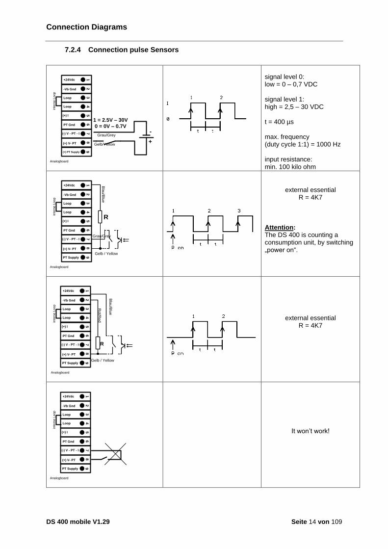
7.2.4 Connection pulse Sensors
+
1 = 2.5V – 30V
0 = 0V – 0.7V-
(+) V- PT
(+) I
45
78
+24Vdc
Loop
PT Gnd
2
-Vb Gnd
13
Loop
6
(-) V - PT - I
9
inte
rne
Lo
op
Grau/Grey
Gelb/Yellow
(+) PT Supply
Analogboard
signal level 0: low = 0 – 0,7 VDC signal level 1: high = 2,5 – 30 VDC t = 400 µs max. frequency (duty cycle 1:1) = 1000 Hz input resistance: min. 100 kilo ohm
(+) V- PT
(+) I
45
78
+24Vdc
Loop
PT Gnd
2
-Vb Gnd
13
Loop
6
(-) V - PT - I
9
PT Supply
R
inte
rne
Lo
op
Bla
u/B
lue
Gelb / Yellow
Grau/Grey
Analogboard
external essential R = 4K7
Attention: The DS 400 is counting a consumption unit, by switching „power on“.
(+) V- PT
(+) I
45
78
+24Vdc
Loop
PT Gnd
2-Vb Gnd
13
Loop
6
(-) V - PT - I
9
PT Supply
R
inte
rne
Lo
op
Ro
t/Re
d
Bla
u/B
lue
Gelb / Yellow
Analogboard
external essential
R = 4K7
(+) V- PT
(+) I
45
78
+24Vdc
Loop
PT Gnd
2
-Vb Gnd
13
Loop
6
(-) V - PT - I
9
PT Supply
inte
rne
Lo
op
Analogboard
It won’t work!
Connection Diagrams
DS 400 mobile V1.29 Seite 15 von 109
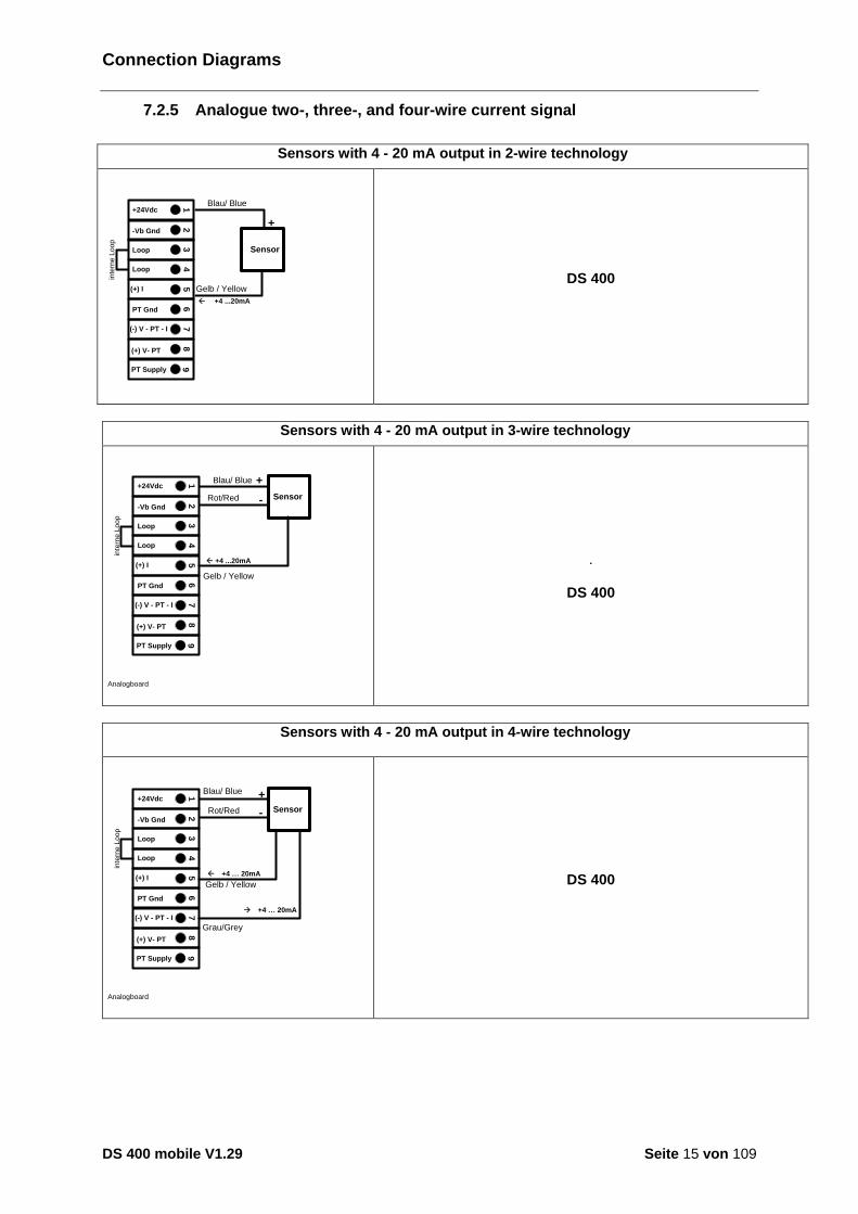
7.2.5 Analogue two-, three-, and four-wire current signal
Sensors with 4 - 20 mA output in 2-wire technology
Gelb / Yellow
Sensor
+
inte
rne
Lo
op
Blau/ Blue
(+) V- PT
(+) I
45
78
+24Vdc
Loop
PT Gnd
2
-Vb Gnd
13
Loop
6
(-) V - PT - I
9
PT Supply
ß +4 ...20mA
Analogboard
DS 400
Sensors with 4 - 20 mA output in 3-wire technology
Sensor
(+) V- PT
(+) I
45
78
+24Vdc
Loop
PT Gnd
2
-Vb Gnd
13
Loop
6
(-) V - PT - I
9
PT Supply
inte
rne
Lo
op
-
ß +4 ...20mA
+Blau/ Blue
Rot/Red
Gelb / Yellow
Analogboard
.
DS 400
Sensors with 4 - 20 mA output in 4-wire technology
Sensor
+
(+) V- PT
(+) I
45
78
+24Vdc
Loop
PT Gnd
2
-Vb Gnd
13
Loop
6
(-) V - PT - I
9
PT Supply
inte
rne
Lo
op
-
ß +4 … 20mA
à +4 … 20mA
Blau/ Blue
Rot/Red
Gelb / Yellow
Grau/Grey
Analogboard
DS 400

Connection Diagrams
DS 400 mobile V1.29 Seite 16 von 109
7.2.6 Three- and four-wire power supply 0 - 1/10/30 VDC
Sensor
+
(+) V- PT
(+) I
45
78
+24Vdc
Loop
PT Gnd
2
-Vb Gnd
13
Loop
6
(-) V - PT - I
9
PT Supply
inte
rne
Lo
op
-
+
Rot/Red
Gelb / Yellow
Blau/ Blue
Analogboard
Sensor with voltage output in 3-wire technology
Sensor
+
(+) V- PT
(+) I
45
78
+24Vdc
Loop
PT Gnd
2
-Vb Gnd
13
Loop
6
(-) V - PT - I
9
PT Supply
inte
rne
Lo
op
-
+-
Blau/ Blue
Rot/Red
Grau/Grey
Gelb / Yellow
Analogboard
Sensor with voltage output in 4-wire technology
Connection Diagrams
DS 400 mobile V1.29 Seite 17 von 109
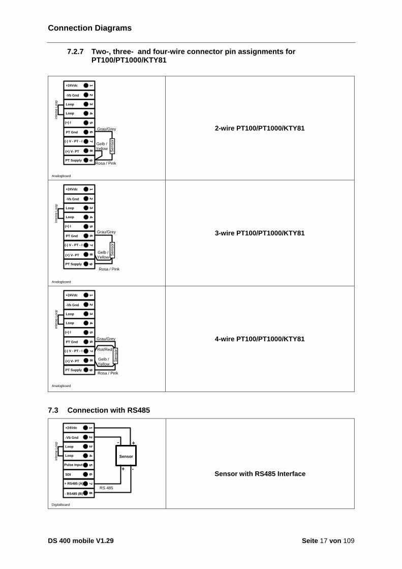
7.2.7 Two-, three- and four-wire connector pin assignments for PT100/PT1000/KTY81
(+) V- PT
(+) I
45
78
+24Vdc
Loop
PT Gnd
2
-Vb Gnd
13
Loop
6
(-) V - PT - I
9
PT Supply
inte
rne
Lo
op
Se
nso
r
Grau/Grey
Gelb /
Yellow
Rosa / Pink
Analogboard
2-wire PT100/PT1000/KTY81
(+) V- PT
(+) I
45
78
+24Vdc
Loop
PT Gnd
2
-Vb Gnd
13
Loop
6
(-) V - PT - I
9
PT Supply
inte
rne
Lo
op
Se
nso
r
Grau/Grey
Gelb /
Yellow
Rosa / Pink
Analogboard
3-wire PT100/PT1000/KTY81
(+) V- PT
(+) I
45
78
+24Vdc
Loop
PT Gnd
2
-Vb Gnd
13
Loop6
(-) V - PT - I
9
PT Supply
inte
rne
Lo
op
Se
nso
r
Gelb /
Yellow
Rosa / Pink
Grau/Grey
Rot/Red
Analogboard
4-wire PT100/PT1000/KTY81
7.3 Connection with RS485
- RS485 (B)
+ RS485 (A)
Pulse Input
45
67
8
+24Vdc
Loop
SDI
2
-Vb Gnd
13
Loop
Sensor
+-
inte
rne
Lo
op
RS 485
+ -
Digitalboard
Sensor with RS485 Interface
Connect the DS400 with a PC
DS 400 mobile V1.29 Seite 18 von 109
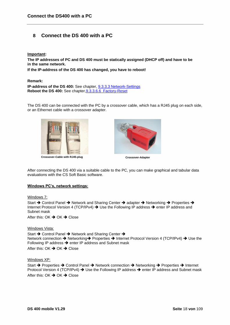
8 Connect the DS 400 with a PC
Important:
The IP addresses of PC and DS 400 must be statically assigned (DHCP off) and have to be in the same network.
If the IP-address of the DS 400 has changed, you have to reboot!
Remark:
IP-address of the DS 400: See chapter, 9.3.3.3 Network-Settings Reboot the DS 400: See chapter,9.3.3.6.6 Factory-Reset
The DS 400 can be connected with the PC by a crossover cable, which has a RJ45 plug on each side, or an Ethernet cable with a crossover adapter.
Crossover-Cable with RJ45-plug
After connecting the DS 400 via a suitable cable to the PC, you can make graphical and tabular data evaluations with the CS Soft Basic software.
Windows PC’s, network settings:
Windows 7:
Start Control Panel Network and Sharing Center adapter Networking Properties Internet Protocol Version 4 (TCP/IPv4) Use the Following IP address enter IP address and Subnet mask
After this: OK OK Close
Windows Vista:
Start Control Panel Network and Sharing Center Network connection Networking Properties Internet Protocol Version 4 (TCP/IPv4) Use the Following IP address enter IP address and Subnet mask
After this: OK OK Close
Windows XP:
Start Properties Control Panel Network connection Networking Properties Internet Protocol Version 4 (TCP/IPv4) Use the Following IP address enter IP address and Subnet mask
After this: OK OK Close
Crossover-Adapter
Operation DS 400 / Main menu (Home)
DS 400 mobile V1.29 Seite 19 von 109
9 Operation DS 400
The operation is largely self-explanatory and menu-driven via the touch panel. The selection of the respective menu items occur via short "tapping" with the finger or a soft round pen. Attention: Please use no pens or other objects with sharp edges! The foil can be damaged! After sensors are connected, they also have to be configured. Inputs or changes can be made with all white deposit fields. The measured values can be represented as a curve or values. Words in green font refer mainly to the pictures in the section of the chapter, but also on important menu paths or menu items that are related to be in green font. The menu navigation is generally in a green font! The table of contents and chapter references in blue font contain links to the respective chapter title.
9.1 Switching on / off of the DS400 mobile
To switch on / off the DS400 mobile you have to press ( >= 3sec) the on / off knob. A short press of the on / off knob during operation opens a popup with indication of the remaining operation time.
9.2 Main menu (Home)
From the main menu, you can reach every available item.
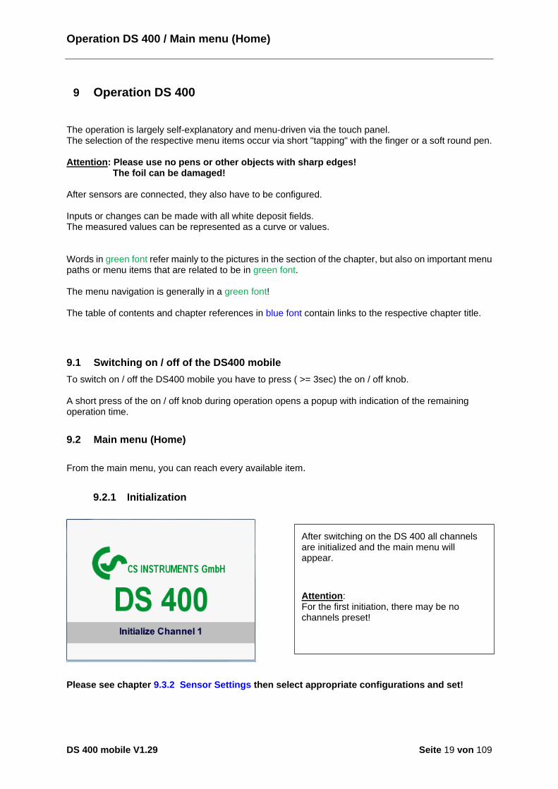
9.2.1 Initialization
Please see chapter 9.3.2 Sensor Settings then select appropriate configurations and set!
After switching on the DS 400 all channels are initialized and the main menu will appear.
Attention: For the first initiation, there may be no channels preset!

Main menu
DS 400 mobile V1.29 Seite 20 von 109
9.2.2 Main menu after initialization
Important: Before the first sensor setting is made, the language and time should be set! Remark:
Chapter 9.3.3.1 Language Main Settings Device Settings Set Language Chapter 9.3.3.2 Date & Time Main Settings Device Settings Date & Time
Hard- and Software-Version
Alarm display
Status Datalogger
interval data logger and remaining memory capacity
Date & Time
Settings / Password-Settings
DS 400 mobile V1.29 Seite 21 von 109
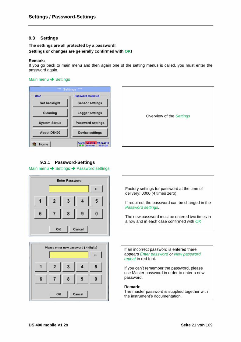
9.3 Settings
The settings are all protected by a password!
Settings or changes are generally confirmed with OK! Remark: If you go back to main menu and then again one of the setting menus is called, you must enter the password again. Main menu Settings
9.3.1 Password-Settings
Main menu Settings Password settings
Enter PasswordPlease enter new password ( 4 digits)
If an incorrect password is entered there appears Enter password or New password repeat in red font. If you can’t remember the password, please use Master password in order to enter a new password. Remark: The master password is supplied together with the instrument’s documentation.
Factory settings for password at the time of delivery: 0000 (4 times zero). If required, the password can be changed in the Password settings. The new password must be entered two times in a row and in each case confirmed with OK
Overview of the Settings
Sensor-Settings
DS 400 mobile V1.29 Seite 22 von 109
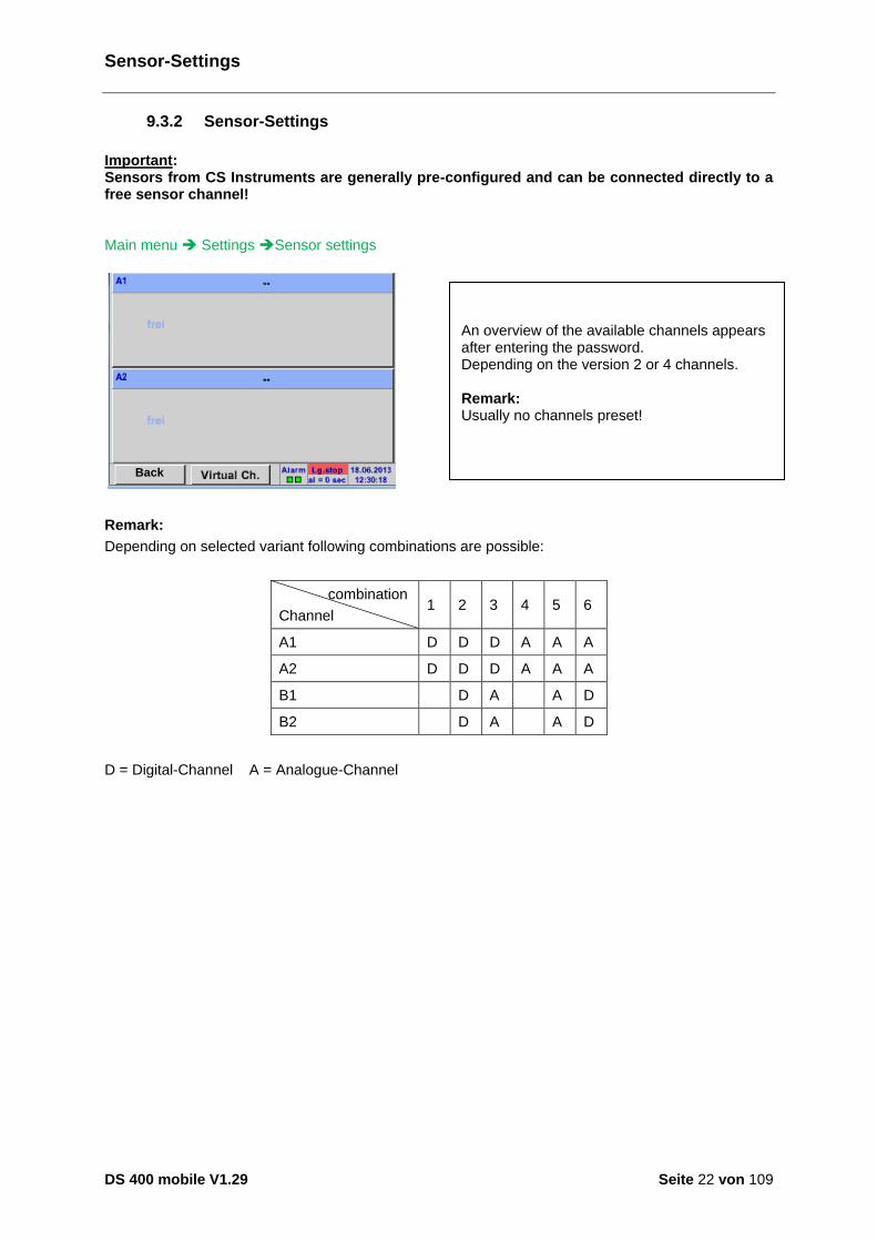
9.3.2 Sensor-Settings
Important: Sensors from CS Instruments are generally pre-configured and can be connected directly to a free sensor channel! Main menu Settings Sensor settings
Back
Remark:
Depending on selected variant following combinations are possible:
combination
Channel 1 2 3 4 5 6
A1 D D D A A A
A2 D D D A A A
B1 D A A D
B2 D A A D
D = Digital-Channel A = Analogue-Channel
An overview of the available channels appears after entering the password. Depending on the version 2 or 4 channels. Remark: Usually no channels preset!

Sensor-Settings
DS 400 mobile V1.29 Seite 23 von 109
9.3.2.1 Choice of the sensor type (For example type CS-Digital sensor)
Main menu Settings Sensor settings A1
Main menu Settings Sensor settings A1 Type description field CS-Digital
If still no sensor has been configured, the Type No Sensor appears. By pushing the description field Type No Sensor the list of sensor types appears (see next step).
Now the Type CS-Digital is selected for the VA/FA 400 series and confirmed by pressing the OK button.
Sensor-Settings / name and recording of measurement data
DS 400 mobile V1.29 Seite 24 von 109
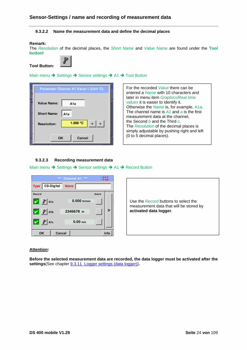
9.3.2.2 Name the measurement data and define the decimal places
Remark: The Resolution of the decimal places, the Short Name and Value Name are found under the Tool button!
Tool Button: Main menu Settings Sensor settings A1 Tool Button
9.3.2.3 Recording measurement data
Main menu Settings Sensor settings A1 Record Button
0.000 ltr/min
2345678 ltr
0.00 m/s
Attention: Before the selected measurement data are recorded, the data logger must be activated after the settings(See chapter 9.3.11 Logger settings (data logger)).
For the recorded Value there can be entered a Name with 10 characters and later in menu item Graphics/Real time values it is easier to identify it. Otherwise the Name is, for example, A1a. The channel name is A1 and a is the first measurement data at the channel, the Second b and the Third c. The Resolution of the decimal places is simply adjustable by pushing right and left (0 to 5 decimal places).
Use the Record buttons to select the measurement data that will be stored by activated data logger.

Sensor-Settings / Alarm-Settings
DS 400 mobile V1.29 Seite 25 von 109
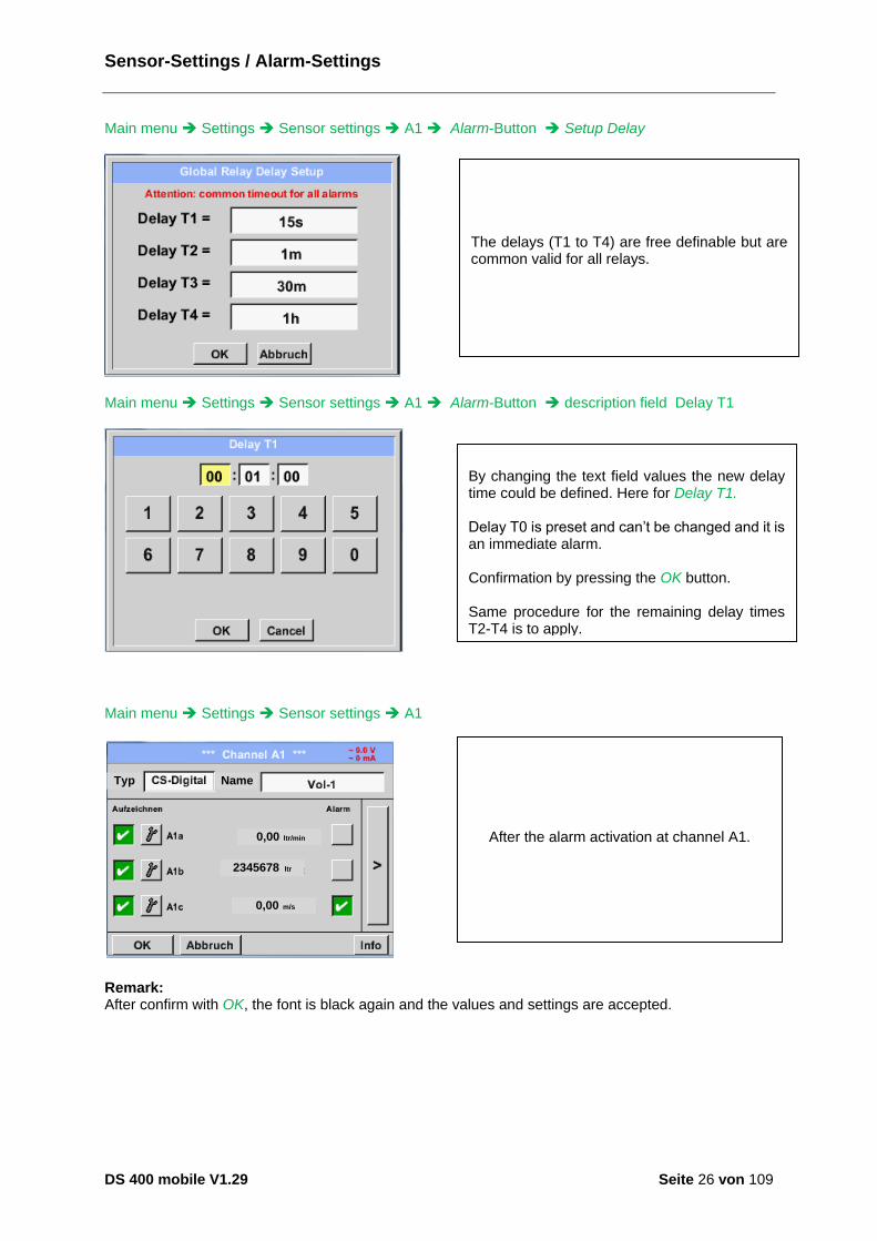
9.3.2.4 Alarm-Settings
Remark: For DS400 mobile only the alarm-overview is displayed, alarm relays are not accessible.. Main menu Settings Sensor settings A1 Alarm-Button By pushing an alarm button, the following window appears:
Main menu Settings Sensor settings A1 Alarm-Button Alarm-1- und Alarm-2-buttons + Relays-buttons
100.000
110.000
75.000
85.000
Main menu Settings Sensor settings A1 Alarm-Button Relay-buttons
In the alarm settings an Alarm 1 and Alarm 2 incl. Hysteresis can be entered for each channel. In the menu Alarm overview (can be reached from the main menu), the alarm settings are clearly represented.
E.g., set the Alarm 1 to relay 1 and the Alarm 2 to relay 2.
It is possible to select from 5 different delays. T0 is preset to no delay. The delays (T1 to T4) are free definable but are common valid for all relays.
Sensor-Settings / Alarm-Settings
DS 400 mobile V1.29 Seite 26 von 109
Main menu Settings Sensor settings A1 Alarm-Button Setup Delay
Main menu Settings Sensor settings A1 Alarm-Button description field Delay T1
Main menu Settings Sensor settings A1
Typ Name
0,00 ltr/min
2345678 ltr
0,00 m/s
Remark: After confirm with OK, the font is black again and the values and settings are accepted.
After the alarm activation at channel A1.
The delays (T1 to T4) are free definable but are common valid for all relays.
By changing the text field values the new delay time could be defined. Here for Delay T1. Delay T0 is preset and can’t be changed and it is an immediate alarm. Confirmation by pressing the OK button. Same procedure for the remaining delay times T2-T4 is to apply.
Sensor-Settings / More Settings (scale analogue output)
DS 400 mobile V1.29 Seite 27 von 109
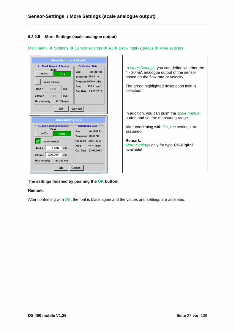
9.3.2.5 More Settings (scale analogue output)
Main menu Settings Sensor settings A1 arrow right (2.page) More settings
m³/h293.0
1000.0
110.0
m³/h
m³/h
0.000
200.000
293.00
1000.00
110.00
The settings finished by pushing the OK button! Remark: After confirming with OK, the font is black again and the values and settings are accepted.
In More-Settings, you can define whether the 4 - 20 mA analogue output of the sensor based on the flow rate or velocity. The green highlighted description field is selected! In addition, you can push the scale manual button and set the measuring range. After confirming with OK, the settings are assumed. Remark: More-Settings only for type CS-Digital available!
Sensor-Settings / Dew point sensor Typ CS-Digital
DS 400 mobile V1.29 Seite 28 von 109
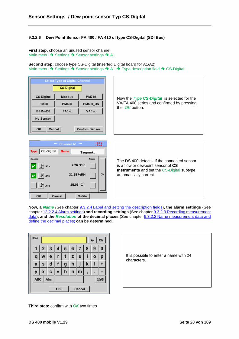
9.3.2.6 Dew Point Sensor FA 400 / FA 410 of type CS-Digital (SDI Bus)
First step: choose an unused sensor channel Main menu Settings Sensor settings A1 Second step: choose type CS-Digital (inserted Digital board for A1/A2) Main menu Settings Sensor settings A1 Type description field CS-Digital
7,26 °Ctd
31,35 %RH
25,03 °C
Now, a Name (See chapter 9.3.2.4 Label and setting the description fields), the alarm settings (See chapter 12.2.2.4 Alarm settings) and recording settings (See chapter 9.3.2.3 Recording measurement data), and the Resolution of the decimal places (See chapter 9.3.2.2 Name measurement data and define the decimal places) can be determined.
Third step: confirm with OK two times
The DS 400 detects, if the connected sensor is a flow or dewpoint sensor of CS Instruments and set the CS-Digital subtype automatically correct.
Now the Type CS-Digital is selected for the VA/FA 400 series and confirmed by pressing the OK button.
It is possible to enter a name with 24 characters.
Sensor-Settings / Dew point sensor Typ CS-Digital
DS 400 mobile V1.29 Seite 29 von 109
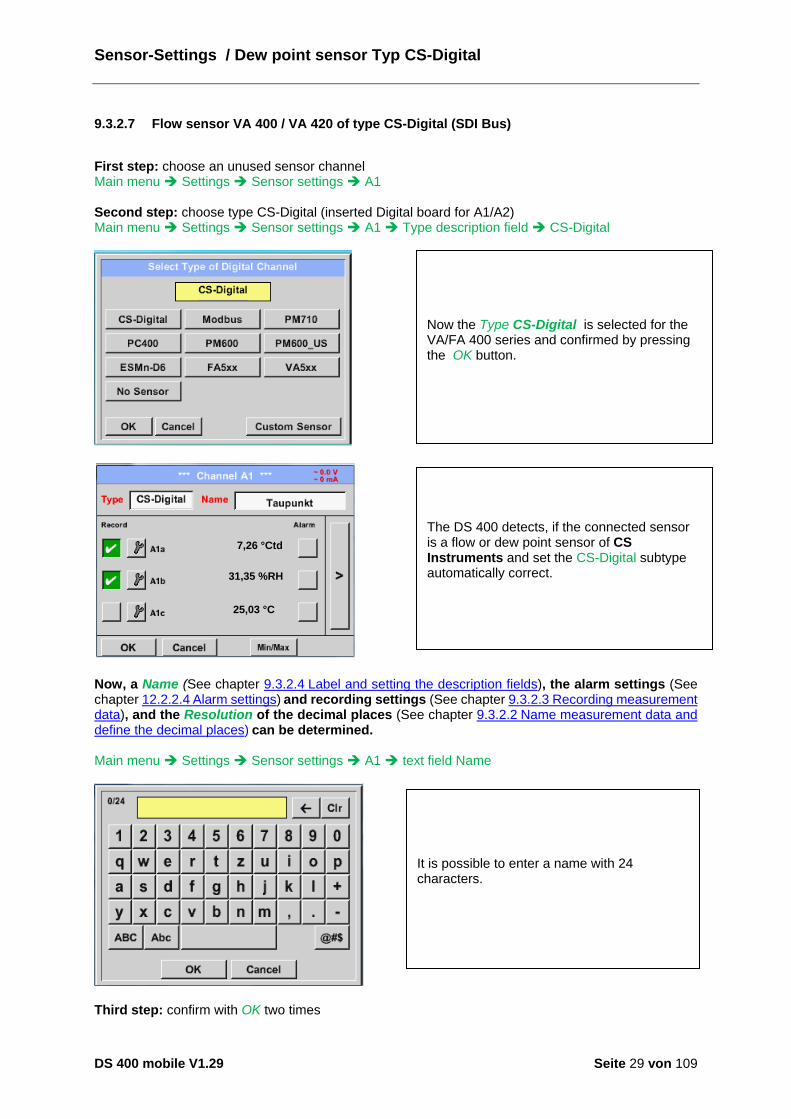
9.3.2.7 Flow sensor VA 400 / VA 420 of type CS-Digital (SDI Bus)
First step: choose an unused sensor channel Main menu Settings Sensor settings A1 Second step: choose type CS-Digital (inserted Digital board for A1/A2) Main menu Settings Sensor settings A1 Type description field CS-Digital
7,26 °Ctd
31,35 %RH
25,03 °C
Now, a Name (See chapter 9.3.2.4 Label and setting the description fields), the alarm settings (See chapter 12.2.2.4 Alarm settings) and recording settings (See chapter 9.3.2.3 Recording measurement data), and the Resolution of the decimal places (See chapter 9.3.2.2 Name measurement data and define the decimal places) can be determined. Main menu Settings Sensor settings A1 text field Name
Third step: confirm with OK two times
The DS 400 detects, if the connected sensor is a flow or dew point sensor of CS Instruments and set the CS-Digital subtype automatically correct.
Now the Type CS-Digital is selected for the VA/FA 400 series and confirmed by pressing the OK button.
It is possible to enter a name with 24 characters.
Sensor-Settings / Dew Point sensor Type CS-Digital
DS 400 mobile V1.29 Seite 30 von 109
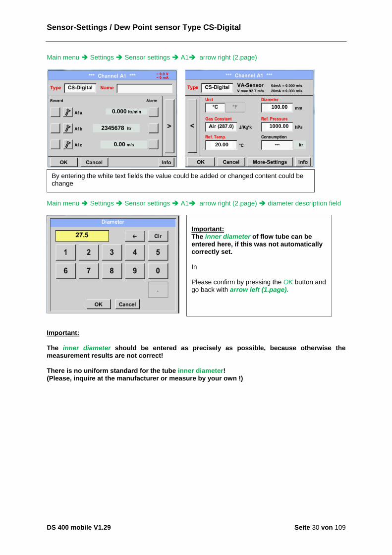
Main menu Settings Sensor settings A1 arrow right (2.page)
0.000 ltr/min
2345678 ltr
0.00 m/s
ltr20.00
100.00
1000.00
Main menu Settings Sensor settings A1 arrow right (2.page) diameter description field
Important: The inner diameter should be entered as precisely as possible, because otherwise the measurement results are not correct! There is no uniform standard for the tube inner diameter! (Please, inquire at the manufacturer or measure by your own !)
Important: The inner diameter of flow tube can be entered here, if this was not automatically correctly set. In Please confirm by pressing the OK button and go back with arrow left (1.page).
By entering the white text fields the value could be added or changed content could be change
Sensor-Settings / Dew Point sensor Type CS-Digital
DS 400 mobile V1.29 Seite 31 von 109
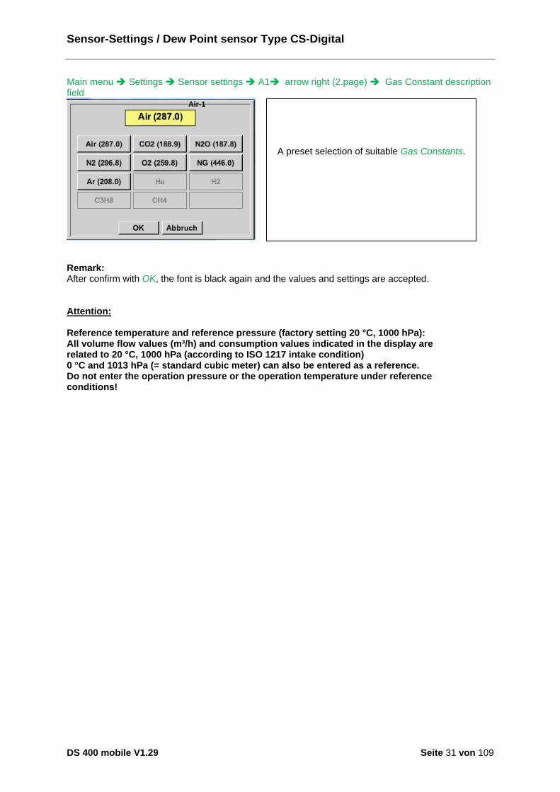
Main menu Settings Sensor settings A1 arrow right (2.page) Gas Constant description field
Remark: After confirm with OK, the font is black again and the values and settings are accepted. Attention: Reference temperature and reference pressure (factory setting 20 °C, 1000 hPa): All volume flow values (m³/h) and consumption values indicated in the display are related to 20 °C, 1000 hPa (according to ISO 1217 intake condition) 0 °C and 1013 hPa (= standard cubic meter) can also be entered as a reference. Do not enter the operation pressure or the operation temperature under reference conditions!
Air-1
A preset selection of suitable Gas Constants.
Sensor-Settings / Dew point sensor Type FA 5xx
DS 400 mobile V1.29 Seite 32 von 109
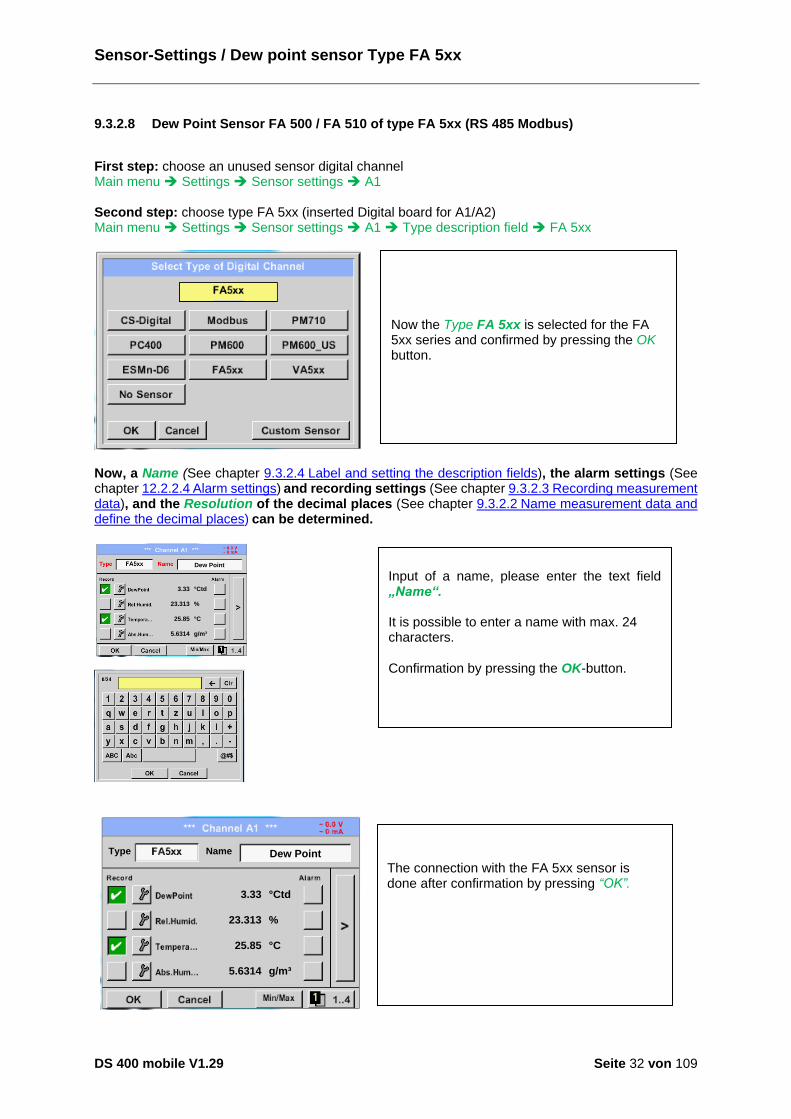
9.3.2.8 Dew Point Sensor FA 500 / FA 510 of type FA 5xx (RS 485 Modbus)
First step: choose an unused sensor digital channel Main menu Settings Sensor settings A1 Second step: choose type FA 5xx (inserted Digital board for A1/A2) Main menu Settings Sensor settings A1 Type description field FA 5xx
Now, a Name (See chapter 9.3.2.4 Label and setting the description fields), the alarm settings (See chapter 12.2.2.4 Alarm settings) and recording settings (See chapter 9.3.2.3 Recording measurement data), and the Resolution of the decimal places (See chapter 9.3.2.2 Name measurement data and define the decimal places) can be determined.
3.33
23.313
25.85
5.6314
°Ctd
%
°C
g/m³
Dew Point
3.33
23.313
25.85
5.6314
°Ctd
%
°C
g/m³
Dew PointNameType
Now the Type FA 5xx is selected for the FA 5xx series and confirmed by pressing the OK button.
Input of a name, please enter the text field „Name“. It is possible to enter a name with max. 24 characters.
Confirmation by pressing the OK-button.
The connection with the FA 5xx sensor is done after confirmation by pressing “OK”.

Sensor-Settings / Dew point sensor Type FA 5xx
DS 400 mobile V1.29 Seite 33 von 109
9.3.2.8.1 Settings Dew point sensor FA 500 FA 510
9.3.2.8.1.1 Unit selection for temperature and humidity
Main menu Settings Sensor settings A1 arrow right (2.page)
9.3.2.8.2 Definition of the System pressure (relative pressure value)
Actual there are 2 possibilities to define system pressure (input as relative pressure value)
System pressure as a fixed value
System pressure taken over from an external pressure sensor
Main menu Settings Sensor settings A1 arrow right (2.page) Pressure Setting Fixed
The definition of the fixed value system pressure value is done by activating the button "fixed", but this is only required in case a ext. pressure probe is connected. The value is entered in the corresponding text field. The unit can be freely selected, selection menu is opened by pressing the corresponding button units Confirm the settings by pressing the OK button.
Unit selection for temperature and humidity by pressing the button °C, °F, g/m³ or mg/m³. Confirm the settings by pressing the OK button.

Sensor-Settings / Dew point sensor Type FA 5xx
DS 400 mobile V1.29 Seite 34 von 109
Main menu Settings Sensor settings A1 arrow right (2.page)Pressure Setting Sensor
Cancel
Back
9.3.2.8.3 Definition of Reference pressure (absolute pressure value)
Main menu Settings Sensor settings A1 arrow right (2.page)Pressure Setting Textfield Ref.Pressure
By using an ext. pressure sensor, which is detected automatically e.g. here at input B1, the button Sensor has to be activated. With activation of the text field „Sys Pressure“ the corresponding channel with the required measuring value could be selected Only values with pressure units can be selected. Confirm the settings by pressing the OK button.
Reference pressure is the pressure for that the dew point in relaxation will be back-calculated. Default- Value is 1013 mbar (Atm. Pressure). Confirm the settings by pressing the OK button.
Sensor-Settings / Dew point sensor Type FA 5xx
DS 400 mobile V1.29 Seite 35 von 109
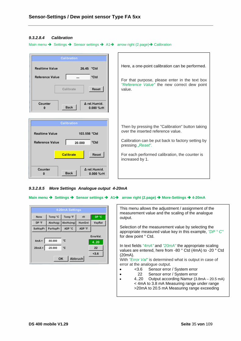
9.3.2.8.4 Calibration
Main menu Settings Sensor settings A1 arrow right (2.page) Calibration
26.45
9.3.2.8.5 More Settings Analogue output 4-20mA
Main menu Settings Sensor settings A1 arrow right (2.page) More-Settings 4-20mA
22
<3.6
Here, a one-point calibration can be performed. For that purpose, please enter in the text box "Reference Value" the new correct dew point value. Then by pressing the "Calibration" button taking over the inserted reference value. Calibration can be put back to factory setting by pressing „Reset“. For each performed calibration, the counter is increased by 1.
This menu allows the adjustment / assignment of the measurement value and the scaling of the analogue output. Selection of the measurement value by selecting the appropriate measured value key in this example, “DP ° C" for dew point ° Ctd. In text fields "4mA" and "20mA" the appropriate scaling values are entered, here from -80 ° Ctd (4mA) to -20 ° Ctd (20mA). With "Error Val" is determined what is output in case of error at the analogue output.
<3.6 Sensor error / System error
22 Sensor error / System error 4..20 Output according Namur (3.8mA – 20.5 mA)
< 4mA to 3.8 mA Measuring range under range >20mA to 20.5 mA Measuring range exceeding
Sensor - Settings / Flow sensor Type VA 5xx
DS 400 mobile V1.29 Seite 36 von 109
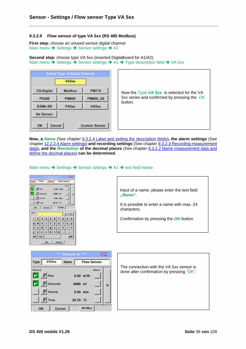
9.3.2.9 Flow sensor of type VA 5xx (RS 485 Modbus)
First step: choose an unused sensor digital channel Main menu Settings Sensor settings A1 Second step: choose type VA 5xx (inserted Digitalboard for A1/A2) Main menu Settings Sensor settings A1 Type description field VA 5xx
Now, a Name (See chapter 9.3.2.4 Label and setting the description fields), the alarm settings (See chapter 12.2.2.4 Alarm settings) and recording settings (See chapter 9.3.2.3 Recording measurement data), and the Resolution of the decimal places (See chapter 9.3.2.2 Name measurement data and define the decimal places) can be determined. Main menu Settings Sensor settings A1 text field Name
0.00
4589
0.00
25.70
m³/h
m³
m/s
°C
Flow Sensor
0.00
4589
0.00
25.70
m³/h
m³
m/s
°C
Flow SensorType Name
The connection with the VA 5xx sensor is done after confirmation by pressing “OK”.
Now the Type VA 5xx is selected for the VA 5xx series and confirmed by pressing the OK button.
Input of a name, please enter the text field „Name“. It is possible to enter a name with max. 24 characters. Confirmation by pressing the OK-button.
Sensor - Settings / Flow sensor Type VA 5xx
DS 400 mobile V1.29 Seite 37 von 109
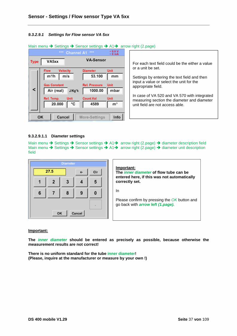
9.3.2.9.1 Settings for Flow sensor VA 5xx
Main menu Settings Sensor settings A1 arrow right (2.page)
9.3.2.9.1.1 Diameter settings
Main menu Settings Sensor settings A1 arrow right (2.page) diameter description field Main menu Settings Sensor settings A1 arrow right (2.page) diameter unit description field
Important: The inner diameter should be entered as precisely as possible, because otherwise the measurement results are not correct! There is no uniform standard for the tube inner diameter! (Please, inquire at the manufacturer or measure by your own !)
For each text field could be the either a value or a unit be set. Settings by entering the text field and then input a value or select the unit for the appropriate field. In case of VA 520 and VA 570 with integrated measuring section the diameter and diameter unit field are not access able.
Important: The inner diameter of flow tube can be entered here, if this was not automatically correctly set. In Please confirm by pressing the OK button and go back with arrow left (1.page).

Sensor - Settings / Flow sensor Type VA 5xx
DS 400 mobile V1.29 Seite 38 von 109
9.3.2.9.1.2 Gas Constant settings
Main menu Settings Sensor settings A1 arrow right (2.page) Gas Constant description field
Attention: Reference temperature and reference pressure (factory setting 20 °C, 1000 hPa): All volume flow values (m³/h) and consumption values indicated in the display are related to 20 °C, 1000 hPa (according to ISO 1217 intake condition) 0 °C and 1013 hPa (= standard cubic meter) can also be entered as a reference. Do not enter the operation pressure or the operation temperature under reference conditions!
All gases marked in blue and with (real) have been a real gas calibration curve stored in the sensor. Select the gas you require and confirm selection by pressing OK button.

Sensor - Settings / Flow sensor Type VA 5xx
DS 400 mobile V1.29 Seite 39 von 109
9.3.2.9.1.3 Definition of the reference conditions
Here, the desired measured media reference conditions for pressure and temperature can be defined Main menu Settings Sensor settings A1 arrow right (2.page) Ref. Pressure description field Main menu Settings Sensor settings A1 arrow right (2.page) Ref. Pressure Unit description field
Main menu Settings Sensor settings A1 arrow right (2.page) Ref. Temp. description Field Main menu Settings Sensor settings A1 arrow right (2.page) Ref. Temp. Unit description Field
9.3.2.9.1.4 Definition Unit of flow and velocity
Main menu Settings Sensor settings A1 arrow right (2.page) Flow description Field Main menu Settings Sensor settings A1 arrow right (2.page) Velocity description Field
Sensor - Settings / Flow sensor Type VA 5xx
DS 400 mobile V1.29 Seite 40 von 109
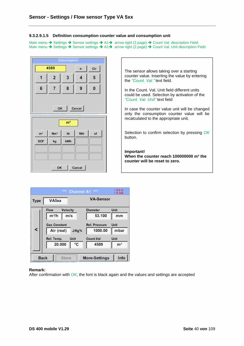
9.3.2.9.1.5 Definition consumption counter value and consumption unit
Main menu Settings Sensor settings A1 arrow right (2.page) Count Val. description Field Main menu Settings Sensor settings A1 arrow right (2.page) Count Val. Unit description Field
Remark: After confirmation with OK, the font is black again and the values and settings are accepted
The sensor allows taking over a starting counter value. Inserting the value by entering the ”Count. Val.” text field. In the Count. Val. Unit field different units could be used. Selection by activation of the “Count. Val. Unit” text field In case the counter value unit will be changed only the consumption counter value will be recalculated to the appropriate unit. Selection to confirm selection by pressing OK button. Important! When the counter reach 100000000 m³ the counter will be reset to zero.

Sensor - Settings / Flow sensor Type VA 5xx
DS 400 mobile V1.29 Seite 41 von 109
9.3.2.9.1.6 Settings analogue output 4-20mA of VA 5xx
Main menu Settings Sensor settings A1 arrow right (2.page) More-Settings 4-20mA Ch1
This menu allows the adjustment / assignment of the measurement value and the scaling of the analogue output by pressing the”4-20mA Ch1” button. Selection of the analogue output measurement value by activating the appropriate measured value key in this example, “Flow". Possible outputs are flow, velocity and temperature. In case of no use, please select “Off”. The analogue output scaling have to possibilities, automatic scaling (default) and a manual scaling by the user. Auto scaling is based on the calibration settings, means 4mA is set to zero and the 20mA value is based on the max. settings here 900m³/h A “manual scaling” needs an activation of the “scale manual” button. In text fields "4mA" and "20mA" the appropriate scaling values are entered, here from zero m³h (4mA) to 300 m³/h (20mA). With "Error Val" it is determined what is the output in case of an error at the analogue output.
2 mA Sensor error / System error
22 mA Sensor error / System error 4..20 Output according Namur (3.8mA – 20.5 mA)
< 4mA to 3.8 mA Measuring range under range >20mA to 20.5 mA Measuring range exceeding
Inputs / changes to be confirmed with “OK” button. Return to main menu with “Back”.
Sensor - Settings / Flow sensor Type VA 5xx
DS 400 mobile V1.29 Seite 42 von 109
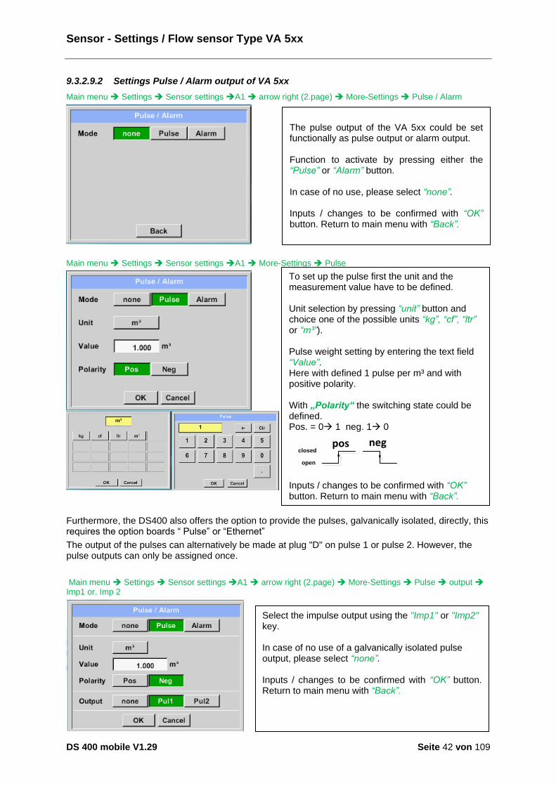
9.3.2.9.2 Settings Pulse / Alarm output of VA 5xx
Main menu Settings Sensor settings A1 arrow right (2.page) More-Settings Pulse / Alarm
Main menu Settings Sensor settings A1 More-Settings Pulse
Furthermore, the DS400 also offers the option to provide the pulses, galvanically isolated, directly, this requires the option boards “ Pulse” or “Ethernet”
The output of the pulses can alternatively be made at plug "D" on pulse 1 or pulse 2. However, the pulse outputs can only be assigned once.
Main menu Settings Sensor settings A1 arrow right (2.page) More-Settings Pulse output Imp1 or. Imp 2
The pulse output of the VA 5xx could be set functionally as pulse output or alarm output. Function to activate by pressing either the “Pulse” or “Alarm” button. In case of no use, please select “none”. Inputs / changes to be confirmed with “OK” button. Return to main menu with “Back”.
To set up the pulse first the unit and the measurement value have to be defined. Unit selection by pressing “unit” button and choice one of the possible units “kg”, “cf”, “ltr” or “m³”). Pulse weight setting by entering the text field “Value”. Here with defined 1 pulse per m³ and with positive polarity. With „Polarity“ the switching state could be defined. Pos. = 0à 1 neg. 1à 0
pos neg
open
closed
Inputs / changes to be confirmed with “OK” button. Return to main menu with “Back”.
Select the impulse output using the "Imp1" or "Imp2" key. In case of no use of a galvanically isolated pulse output, please select “none”. Inputs / changes to be confirmed with “OK” button. Return to main menu with “Back”.
Sensor - Settings / Flow sensor Type VA 5xx
DS 400 mobile V1.29 Seite 43 von 109
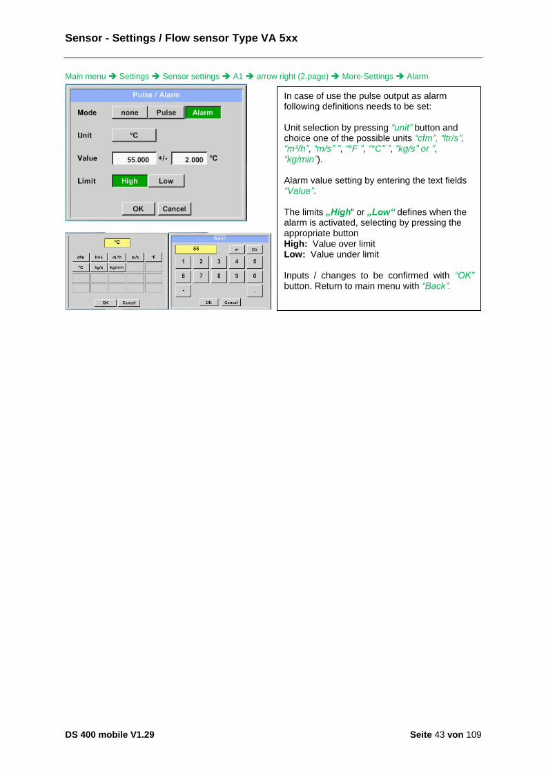
Main menu Settings Sensor settings A1 arrow right (2.page) More-Settings Alarm
In case of use the pulse output as alarm following definitions needs to be set: Unit selection by pressing “unit” button and choice one of the possible units “cfm”, “ltr/s”, “m³/h”, “m/s” ”, “°F ”, “°C” ”, “kg/s” or ”, “kg/min”). Alarm value setting by entering the text fields “Value”. The limits „High“ or „Low“ defines when the alarm is activated, selecting by pressing the appropriate button High: Value over limit Low: Value under limit Inputs / changes to be confirmed with “OK” button. Return to main menu with “Back”.
Sensor - Settings / Flow sensor Type VA 5xx
DS 400 mobile V1.29 Seite 44 von 109
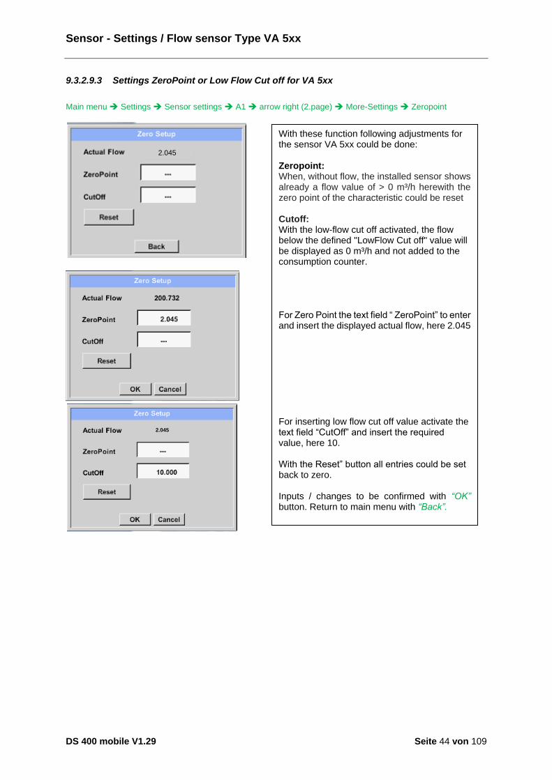
9.3.2.9.3 Settings ZeroPoint or Low Flow Cut off for VA 5xx
Main menu Settings Sensor settings A1 arrow right (2.page) More-Settings Zeropoint
2.045
2.045
With these function following adjustments for the sensor VA 5xx could be done: Zeropoint: When, without flow, the installed sensor shows already a flow value of > 0 m³/h herewith the zero point of the characteristic could be reset Cutoff: With the low-flow cut off activated, the flow below the defined "LowFlow Cut off" value will be displayed as 0 m³/h and not added to the consumption counter. For Zero Point the text field “ ZeroPoint” to enter and insert the displayed actual flow, here 2.045 For inserting low flow cut off value activate the text field “CutOff” and insert the required value, here 10. With the Reset” button all entries could be set back to zero. Inputs / changes to be confirmed with “OK” button. Return to main menu with “Back”.

Sensor-settings / Configuration of Analogue-Sensors
DS 400 mobile V1.29 Seite 45 von 109
9.3.2.10 Configuration of Analogue-Sensors
Applicable only at DS 400 variants with an analogue board equipped. A brief overview of the possible Type of settings with examples. Except CS-Digital, see chapter 9.3.2.1 Choice of the sensor types (For example type CS-Digital sensor) and 9.3.2.6 Dewpoint sensor with type CS-Digital. The Alarm- ,Record buttons, the Resolution of the decimal places and Short Name and Value Name are all described in chapter 9.3.2 Sensor settings.
9.3.2.10.1 Type 0 - 1/10/30 Volt und 0/4 – 20 mA
Main menu Settings Sensor settings B1 Type description field 0 - 1/10/30 V
Main menu Settings Sensor settings B1 arrow right (2.page)
Please see the scale of the sensor (here for example Type 0 - 10V corresponds to 0 - 250 ° C) from the data sheet of the connected sensor. By Scale 0V enter the lower and by Scale10V the upper scale value.
By Scale 0V enter the lower and by Scale10V the upper scale value The Sensor Supply Voltage is switched On, if it´s required by the sensor type, otherwise off (no green hook). Please confirm by pressing the OK button.
It is possible to define an Offset-Value. With the Set Value to-button (Offset) you enter it. The positive or negative difference of the Offset will be displayed. By pressing the Reset-button the Offset will be deleted.

Sensor-settings / Configuration of Analogue-Sensors
DS 400 mobile V1.29 Seite 46 von 109
Main menu Settings Sensor settings B1 arrow right (2.page) description field Unit
Main menu Settings Sensor settings B1 Type description field 0/4 - 20 mA
10.55 bar
Here for example Type 4 - 20 mA.
A preset selection of suitable units by Type 0 - 1/10/30 V and 0/4...20 mA. The different pages could be displayed by pressing the Page-button. In addition, User specific units could be defined Here with the Edit button could analog to description field a User unit be defined.
Sensor-settings / Configuration of Analogue-Sensors
DS 400 mobile V1.29 Seite 47 von 109
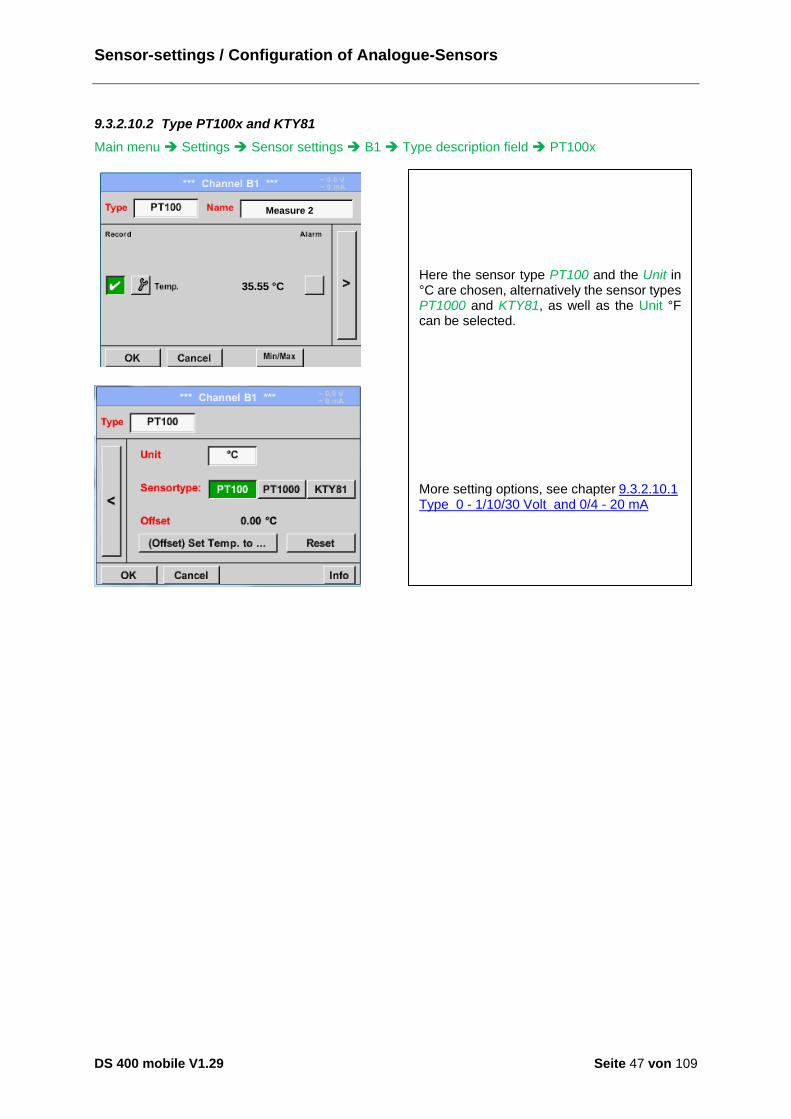
9.3.2.10.2 Type PT100x and KTY81
Main menu Settings Sensor settings B1 Type description field PT100x
35.55 °C
Measure 2
Here the sensor type PT100 and the Unit in °C are chosen, alternatively the sensor types PT1000 and KTY81, as well as the Unit °F can be selected. More setting options, see chapter 9.3.2.10.1 Type 0 - 1/10/30 Volt and 0/4 - 20 mA

Sensor-settings / Configuration of Analogue-Sensors
DS 400 mobile V1.29 Seite 48 von 109
9.3.2.10.3 Type Pulse (Pulse ration)
Main menu Settings Sensor settings B1 Type description field Type description field Pulse
9000 m³/h
367001 m³
50 Hz
m³/h
Main menu Settings Sensor settings B1 arrow right (2.page) Unit Pulses
Typically the value with unit of 1 Pulse is standing on the sensor and can directly entered to the 1 Pulse = description field. Remark: Here, all description fields are already labeled or occupied.
By Unit Pulse you can choose between a flow volume or a power consumption unit.

Sensor-settings / Configuration of Analogue-Sensors
DS 400 mobile V1.29 Seite 49 von 109
Main menu Settings Sensor settings B1 arrow right (2.page) Unit Consumption
m³/h m³/min
m³/h
Main menu Settings Sensor settings B1 arrow right (2.page) Unit Counter
More setting options, see chapter 9.3.2.10.1 Type 0 - 1/10/30 Volt and 0/4 - 20 mA!
Unit of current Consumption by Type Pulse Remark: Example with the unit cubic meters / hour.
The available Units for the Unit of Counter by Type Pulse The counter can be set any time to any value you need.
Sensor-settings / Type „No Sensor“
DS 400 mobile V1.29 Seite 50 von 109
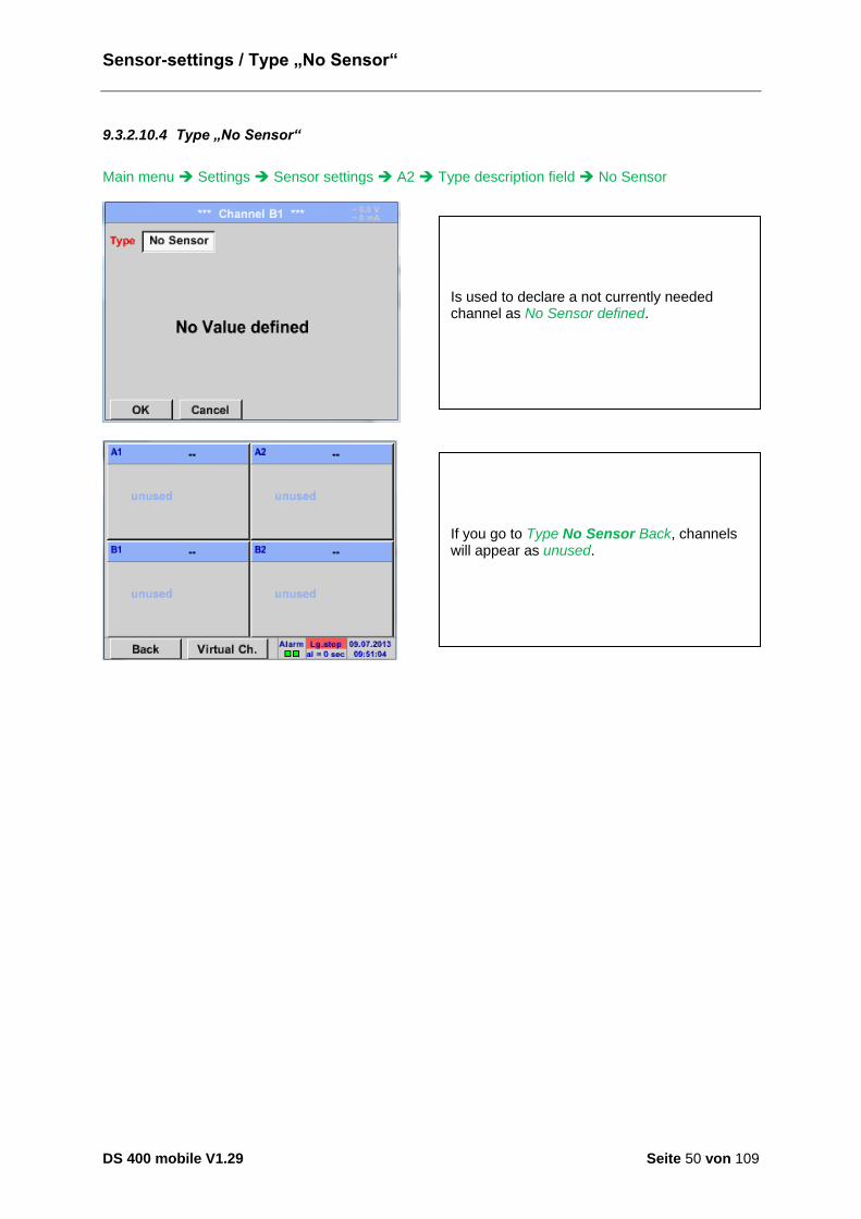
9.3.2.10.4 Type „No Sensor“
Main menu Settings Sensor settings A2 Type description field No Sensor
Is used to declare a not currently needed channel as No Sensor defined.
If you go to Type No Sensor Back, channels will appear as unused.
Sensor-settings / Type „Modbus“
DS 400 mobile V1.29 Seite 51 von 109
9.3.2.11 Type Modbus
9.3.2.11.1 Selection and activation of Sensor-Type Modbus
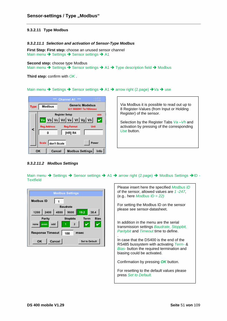
First Step: First step: choose an unused sensor channel Main menu Settings Sensor settings A1 Second step: choose type Modbus Main menu Settings Sensor settings A1 Type description field Modbus Third step: confirm with OK . Main menu Settings Sensor settings A1 arrow right (2.page) Va use
9.3.2.11.2 Modbus Settings
Main menu Settings Sensor settings A1 arrow right (2.page) Modbus Settings ID -Textfield
Via Modbus it is possible to read out up to 8 Register-Values (from Input or Holding Register) of the sensor. Selection by the Register Tabs Va –Vh and activation by pressing of the corresponding Use button.
Please insert here the specified Modbus ID of the sensor, allowed values are 1 -247, (e.g.. here Modbus ID = 22) For setting the Modbus ID on the sensor please see sensor-datasheet. In addition in the menu are the serial transmission settings Baudrate, Stoppbit, Paritybit and Timeout time to define. . In case that the DS400 is the end of the RS485 bussystem with activating Term- & Bias- button the required termination and biasing could be activated. Confirmation by pressing OK button. For resetting to the default values please press Set to Default. Einstellung der Modbus ID sowie Übertragungseinstellungen siehe Sensor-Datenblatt.
Sensor-settings / Type “Modbus”
DS 400 mobile V1.29 Seite 52 von 109
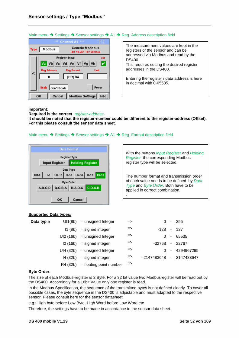
Main menu Settings Sensor settings A1 Reg. Address description field
Important: Required is the correct register-address. It should be noted that the register-number could be different to the register-address (Offset). For this please consult the sensor data sheet.
Main menu Settings Sensor settings A1 Reg. Format description field
Supported Data types:
Data typ:e UI1(8b) = unsigned Integer => 0 - 255
I1 (8b) = signed integer => -128 - 127
UI2 (16b) = unsigned Integer => 0 - 65535
I2 (16b) = signed integer => -32768 - 32767
UI4 (32b) = unsigned Integer => 0 - 4294967295
I4 (32b) = signed integer => -2147483648 - 2147483647
R4 (32b) = floating point number =>
Byte Order:
The size of each Modbus-register is 2 Byte. For a 32 bit value two Modbusregister will be read out by the DS400. Accordingly for a 16bit Value only one register is read.
In the Modbus Specification, the sequence of the transmitted bytes is not defined clearly. To cover all possible cases, the byte sequence in the DS400 is adjustable and must adapted to the respective sensor. Please consult here for the sensor datasheet.
e.g.: High byte before Low Byte, High Word before Low Word etc
Therefore, the settings have to be made in accordance to the sensor data sheet.
The measurement values are kept in the registers of the sensor and can be addressed via Modbus and read by the
DS400. This requires setting the desired register addresses in the DS400. Entering the register / data address is here in decimal with 0-65535.
With the buttons Input Register and Holding Register the corresponding Modbus-register type will be selected. The number format and transmission order of each value needs to be defined by Data Type and Byte Order. Both have to be applied in correct combination. .

Sensor-settings / Type “Modbus”
DS 400 mobile V1.29 Seite 53 von 109
Example :
Holding Register - UI1(8b) - Zahlenwert: 18
Holding Register – UI4(32) - Value: 29235175522 à AE41 5652
Main menu Settings Sensor settings A1 Unit- description field
Selection Register Type Holding Register, Data Type U1(8b) und Byte Order A / B HByte LByte 18 => 00 12 Data Order 1. Byte 2. Byte A 00 12 B 12 00
Selection Register Type Holding Register, Data Type U1(32b) und Byte Order A-B-C-D HWord LWord HByte LByte HByte LByte 29235175522 => AE 41 56 52 Data Order 1.Byte 2.Byte 3.byte 4.Byte A-B-C-D AE 41 56 52 D-C-B-A 52 56 41 AE B-A-D-C 41 AE 52 56 C-D-A-B 56 52 AE 41
By pressing the description field Unit the list with the available units appear Please select the unit by pressing the respective button e.g. m³/h. For validation of the unit please push the button OK To move through the list please press the button Page. In case the unit is not available it is possible to create a user defined unit. Therefore, please select one of the User_X buttons.
Sensor-settings / Type “Modbus”
DS 400 mobile V1.29 Seite 54 von 109
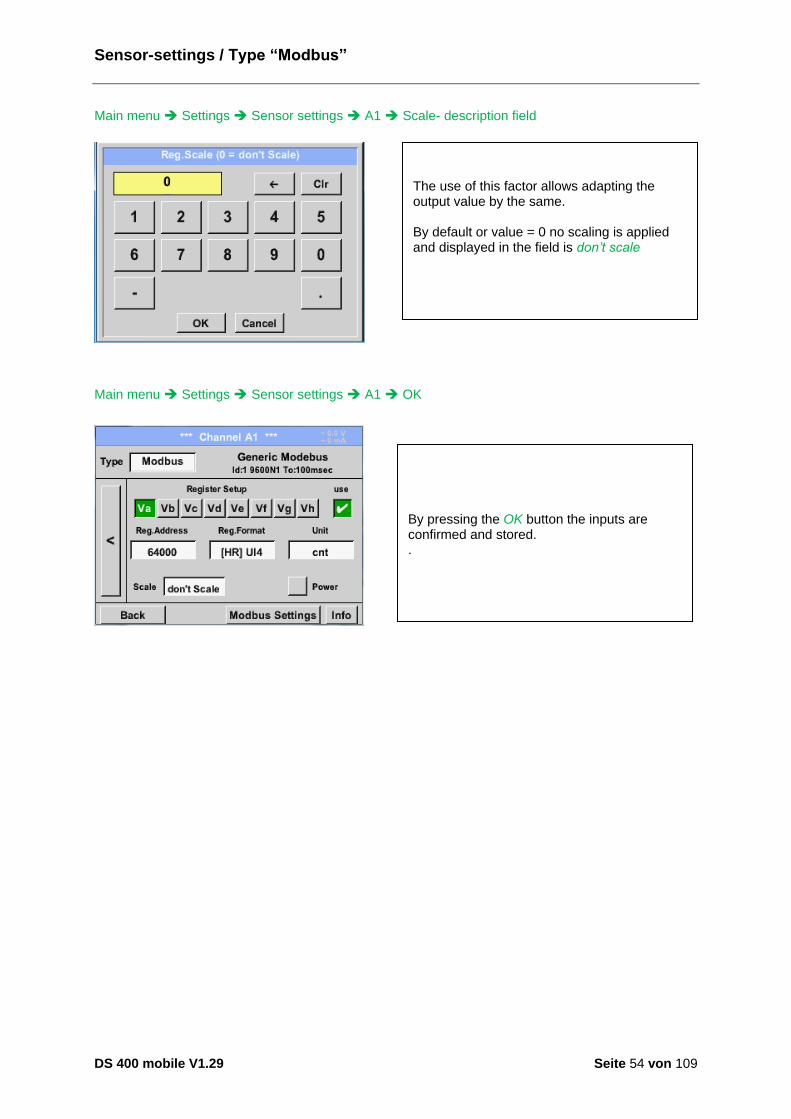
Main menu Settings Sensor settings A1 Scale- description field
Main menu Settings Sensor settings A1 OK
The use of this factor allows adapting the output value by the same. By default or value = 0 no scaling is applied and displayed in the field is don’t scale
By pressing the OK button the inputs are confirmed and stored. .
Custom Sensor
DS 400 mobile V1.29 Seite 55 von 109
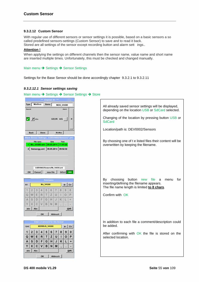
9.3.2.12 Custom Sensor
With regular use of different sensors or sensor settings it is possible, based on a basic sensors a so called predefined sensors-settings (Custom Sensor) to save and to read it back. Stored are all settings of the sensor except recording button and alarm sett ings..
Attention !
When applying the settings on different channels then the sensor name, value name and short name are inserted multiple times. Unfortunately, this must be checked and changed manually.
Main menu Settings Sensor Settings
Settings for the Base Sensor should be done accordingly chapter 9.3.2.1 to 9.3.2.11
9.3.2.12.1 Sensor settings saving
Main menu Settings Sensor Settings Store
122,05 m/s
All already saved sensor settings will be displayed, depending on the location USB or SdCard selected. Changing of the location by pressing button USB or SdCard Location/path is: DEV0002/Sensors By choosing one of t e listed files their content will be overwritten by keeping the filename. By choosing button new file a menu for inserting/defining the filename appears. The file name length is limited to 8 chars. Confirm with OK In addition to each file a comment/description could be added. After confirming with OK the file is stored on the selected location.

Custom Sensor
DS 400 mobile V1.29 Seite 56 von 109
9.3.2.12.2 Sensor settings import
Main menu Settings Sensor Settings A1 Type Textfield Custom Sensor
All already saved sensor settings will be displayed, depending on the location USB or SdCard selected. Changing of the location by pressing button USB or SdCard Then select the required sensor-setting file and confirm it with OK . For a short verification the basetyp of sensor and also the comment stored is displayed By pressing OK the data (settings) are imported. If necessary the naming, recording- and alarm-settings needs to be adapted.
In case a wrong (not compatible) Sensor type (analogue / digital) has selected an error message will be displayed.

Device-Settings / Language
DS 400 mobile V1.29 Seite 57 von 109
9.3.3 Device Settings
Main menu Settings Device settings
9.3.3.1 Language
Main menu Settings Device settings Set language
Overview of Device settings
Here you can select one of 10 languages for the DS 400. .

Device-Settings / Date & Time
DS 400 mobile V1.29 Seite 58 von 109
9.3.3.2 Date & Time
Main menu Settings Device settings Date & Time
By pushing the Time Zone description field and enter the correct UTC, you can set the correct time all over the world.
The summer and wintertime switchover is realized by pushing the Daylight Saving button.

Device-Settings / Network-Settings
DS 400 mobile V1.29 Seite 59 von 109
9.3.3.3 Network-Settings
Main menu Settings Device settings Network-Settings
Subnet Mask and Gateway address are entered in the same way!
Here you can set up and made a connection, with or without DHCP, to a computer. Remark: With activated DHCP (green hook), the automatic integration of the DS 400 in an existing network is possible, without a manual configuration.
For example a IP-Address out of address range of the class C-Net Remark: Private Address range Class A-Net 10.0.0.0 to 10.255.255.255 Private Address range Class B-Net 72.16.0.0 to 172.31.255.255 Private Address range Class C-Net 192.168.0.0 to 192.168.255.255 Subnet Mask: e. g. 255.255.255.0
After pushing, for example the IP address description field, the command window appears, where in the selected yellow area a partial IP address can be entered manually. The Host name can be entered or changed by pushing the description field.
Device-Settings (Relay settings)
DS 400 mobile V1.29 Seite 60 von 109
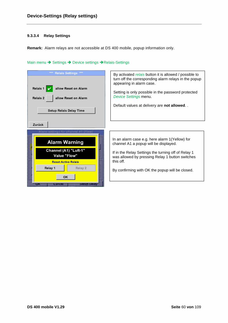
9.3.3.4 Relay Settings
Remark: Alarm relays are not accessible at DS 400 mobile, popup information only.
Main menu Settings Device settings Relais-Settings
By activated relais button it is allowed / possible to turn off the corresponding alarm relays in the popup appearing in alarm case. Setting is only possible in the password protected Device Settings menu. Default values at delivery are not allowed. .
In an alarm case e.g. here alarm 1(Yellow) for channel A1 a popup will be displayed. If in the Relay Settings the turning off of Relay 1 was allowed by pressing Relay 1 button switches this off. By confirming with OK the popup will be closed.
Device-Settings / SD-Card
DS 400 mobile V1.29 Seite 61 von 109
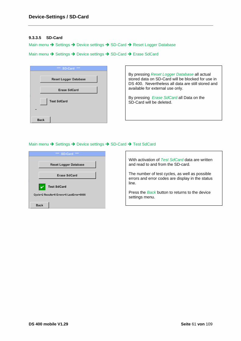
9.3.3.5 SD-Card
Main menu Settings Device settings SD-Card Reset Logger Database Main menu Settings Device settings SD-Card Erase SdCard
Main menu Settings Device settings SD-Card Test SdCard
By pressing Reset Logger Database all actual stored data on SD-Card will be blocked for use in DS 400. Nevertheless all data are still stored and available for external use only. By pressing Erase SdCard all Data on the SD-Card will be deleted.
With activation of Test SdCard data are written and read to and from the SD-card. The number of test cycles, as well as possible errors and error codes are display in the status line. Press the Back button to returns to the device settings menu.
System
DS 400 mobile V1.29 Seite 62 von 109
9.3.3.6 System
9.3.3.6.1 Save system settings
Important: Before updating the DS 400 the system settings should be secured either on a USB or the internal SD-Card! Home Import / Export Export System Settings
Overview of the System features
With Export system settings, all existing sensor settings can be exported to a USB stick or to the internal SD card. It stores all sensor settings including recording-, alarm-, graphics-, value- and name definitions. Storing location could be selected using the buttons SD card or USB. Either a new file could be created by pressing “new file” or an existing file overwritten by selecting a name from the list. The data are stored after confirmation with OK.
System / System update
DS 400 mobile V1.29 Seite 63 von 109
9.3.3.6.2 System update
Important!
System update can only be done with power supply connected to ensure there is a continuous power supply during the update.
Home Settings Device settings System-Update
9.3.3.6.3 Check for Updates
Home Settings Device settings System-Update check USB-Stick for new Updates
If it is required to install an older software version, you have press the button "Force all “.
Overview of System-Update-Functions.
If after pressing the button “Check USB Stick for new Software updates” the following messages appear in the window, is the DS 400 is not properly connected to the USB flash drive or there are no files available.
Is the DS 400 properly connected to the USB drive and there are new versions of the individual software parts available, then they are in red font and <new> marked.
System / System update
DS 400 mobile V1.29 Seite 64 von 109
9.3.3.6.4 Update Firmware
Home Settings Device settings System-Update Update-Firmware The update of DS 400 for all new SW parts starts. Important: If the Reboot system button appears after the update, it must be pushed to restart the DS 400!
9.3.3.6.5 Update Channels
Home Settings Device settings System-Update Update-Channels The update of DS 400 channels starts. Important: If the Reboot system button appears after the update, it must be pushed to restart the DS 400!
Update for Channels DS 400.
System / Factory reset
DS 400 mobile V1.29 Seite 65 von 109
9.3.3.6.6 Factory Reset
Main menu Settings Device settings System Reset to Defaults
Reboot the System here, if you need it!
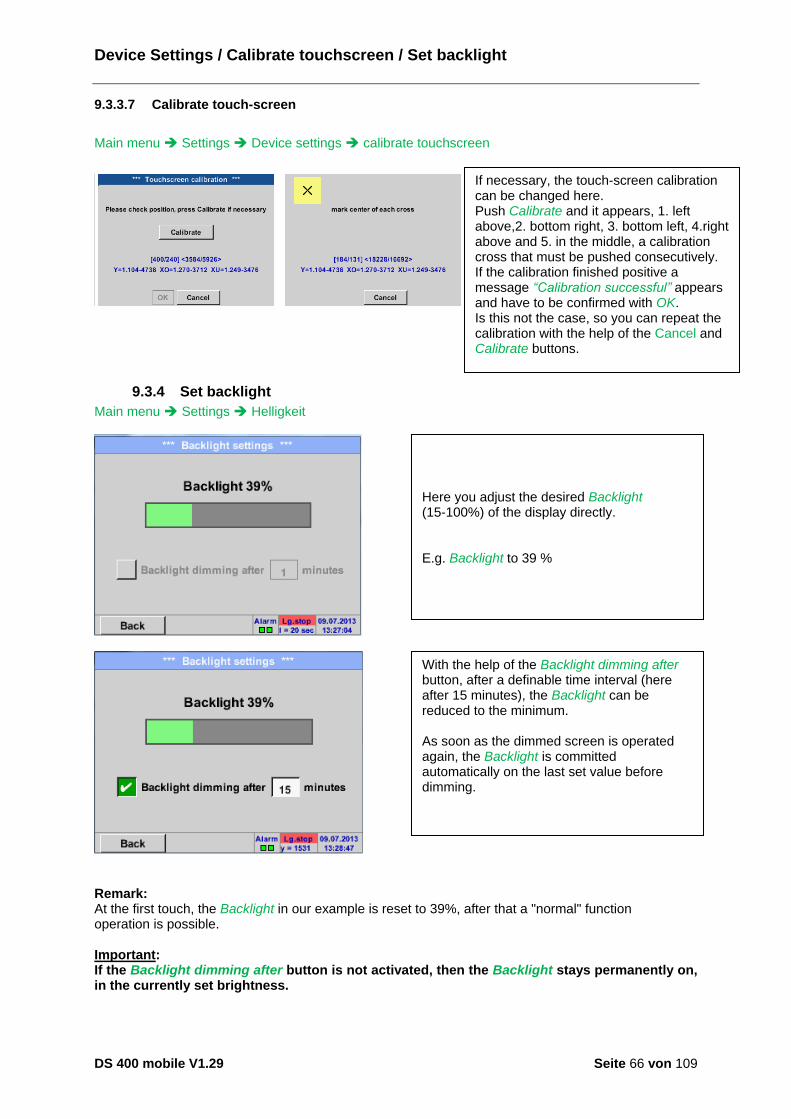
Device Settings / Calibrate touchscreen / Set backlight
DS 400 mobile V1.29 Seite 66 von 109
9.3.3.7 Calibrate touch-screen
Main menu Settings Device settings calibrate touchscreen
9.3.4 Set backlight
Main menu Settings Helligkeit
Remark: At the first touch, the Backlight in our example is reset to 39%, after that a "normal" function operation is possible. Important: If the Backlight dimming after button is not activated, then the Backlight stays permanently on, in the currently set brightness.
If necessary, the touch-screen calibration can be changed here. Push Calibrate and it appears, 1. left above,2. bottom right, 3. bottom left, 4.right above and 5. in the middle, a calibration cross that must be pushed consecutively. If the calibration finished positive a message “Calibration successful” appears and have to be confirmed with OK. Is this not the case, so you can repeat the calibration with the help of the Cancel and Calibrate buttons.
Here you adjust the desired Backlight (15-100%) of the display directly. E.g. Backlight to 39 %
With the help of the Backlight dimming after button, after a definable time interval (here after 15 minutes), the Backlight can be reduced to the minimum. As soon as the dimmed screen is operated again, the Backlight is committed automatically on the last set value before dimming.
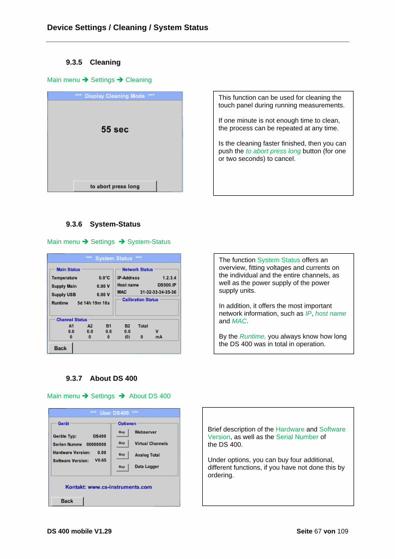
Device Settings / Cleaning / System Status
DS 400 mobile V1.29 Seite 67 von 109
9.3.5 Cleaning
Main menu Settings Cleaning
9.3.6 System-Status
Main menu Settings System-Status
9.3.7 About DS 400
Main menu Settings About DS 400
V0.65
Buy
Buy
Buy
Buy
Brief description of the Hardware and Software Version, as well as the Serial Number of the DS 400. Under options, you can buy four additional, different functions, if you have not done this by ordering.
This function can be used for cleaning the touch panel during running measurements. If one minute is not enough time to clean, the process can be repeated at any time. Is the cleaning faster finished, then you can push the to abort press long button (for one or two seconds) to cancel.
The function System Status offers an overview, fitting voltages and currents on the individual and the entire channels, as well as the power supply of the power supply units. In addition, it offers the most important network information, such as IP, host name and MAC. By the Runtime, you always know how long the DS 400 was in total in operation.

Virtual Channels
DS 400 mobile V1.29 Seite 68 von 109
9.3.8 Virtual Channels (optional)
The option „Virtual Channels“ offers 4 additional channels (no HW Channels) where it is possible to
display calculations of each single HW-Channel, virtual channels and free defined constants as well.
For each „Virtual Channel“ are 8 calculations each with of 3 operands and 2 operations possible.
Possible cases are calculation of:
Specific performance of a compressor(s)
Complete consumption of a compressor( or the sum of several compressors)
Energycost etc.
An example for a specific performance calculation see chapter chapter 9.3.8.6
9.3.8.1 Option „Virtual Channels“ activation
After purchasing of the option „Virtual Channels“ the functionality have to be activated first. Main menu Settings About DS 400
Buy
Buy
Buy
Buy
Enter Code für Option 2
Please push the button Buy for „Virtual Channels“ and you will requested to insert the key-code received Please enter the Key-Code in the text-field and activate the option by pushing the button OK

Virtual Channels
DS 400 mobile V1.29 Seite 69 von 109
9.3.8.2 Virtual Channels Einstellung
Main menu Settings Sensor Settings Virtual Channels
9.3.8.3 Selection of Sensor-type
Main menu Settings Sensor Settings Virtual Channels V1
Main menu Settings Sensor Settings Virtual Channels V1 Type description field
After pushing the button „Virtual Channels“ in the Sensor Settings menu an overview with the 4 available “Virtual Channels” is displayed. Remark: By default, all channels are without settings. .
By pushing the description field Type No Sensor the list of sensor types appears (see next step).
If still no sensor has been configured, the Type No Sensor appears. By pushing the button Generic the virtual channel is selected. With Custom Sensor, a predefined sensor- setting could be loaded, see also chapter 9.3.2.12 Pushing the button No Sensor will reset the virtual channel. Confirmation of selection is done by pressing the button OK.

Virtual Channels
DS 400 mobile V1.29 Seite 70 von 109
Main menu Settings Sensor Settings Virtual Channels V1 Name description field
9.3.8.4 Configuration of each single virtual value
Each virtual channel includes 8 individual calculated values where every value has to be activated separately.
9.3.8.4.1 Activation of a single virtual value
Main menu Settings Sensor Settings Virtual Channels V1 arrow right(2.page) V1a Use
By pushing the Text field Name a Sensor name could be inserted.
Every virtual value has to activated by selecting the respective Value-Button e.g. V1a and pushing of the Use Button.

Virtual Channels
DS 400 mobile V1.29 Seite 71 von 109
9.3.8.4.2 Definition of Operands
Main menu Settings Sensor Settings Virtual Channels V1 arrow right(2.page) 1stOperand
Main menu Settings Sensor Settings Virtual Channels V1 arrow right(2.page) 1stOperand A1
This approach is analogous to the other operands. (1st Operand, 2nd Operand and 3rd Operand) .
By accessing the text field 1st Operand The list with all channels (HW and virtual channels) and const. Value appears.
By pressing a button either for HW-, virtual channel or const. Value e.g. A1 a list of all available measurement channels or measurement values will appear.
Pressing the respective channel button e.g. A1b will select the measurement channel Pressing the button const. Value requests the input of the const. Value into the text field. With button OK the value will validated With the buttons ß and Clr it is possible to correct the input. Button ß deletes the last figure Button Clr clears the whole field

Virtual Channels
DS 400 mobile V1.29 Seite 72 von 109
9.3.8.4.3 Definition of Operations
Main menu Settings Sensor Settings Virtual Channels V1 arrow right (2.page) 1st Operation
This approach is analogous for both operations (1st Operation and 2nd Operation)
9.3.8.4.4 Definition of Unit
Main menu Settings Sensor Settings Virtual Channels V1 arrow right (2.page) Unit
By accessing the text field 1st Operation the list with all available operands appears. Selecting and validation of the operand by pressing the respective operand. Pressing of the button not used deactivates the operation of the dedicated operand.
Please select the unit by pressing the respective button e.g. m³/h. For validation of the unit, please push the button OK To move through the list please press the button Page. In case the unit is not available, it is possible to create a user-defined unit. Therefore, please select one of the User_X buttons.
By accessing the text field Unit of Result the list with all available units appears
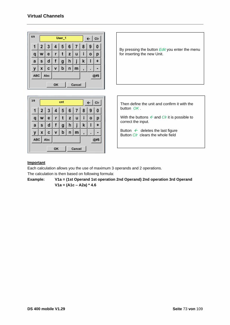
Virtual Channels
DS 400 mobile V1.29 Seite 73 von 109
Important
Each calculation allows you the use of maximum 3 operands and 2 operations.
The calculation is then based on following formula:
Example: V1a = (1st Operand 1st operation 2nd Operand) 2nd operation 3rd Operand
V1a = (A1c – A2a) * 4.6
Then define the unit and confirm it with the button OK . With the buttons ß and Clr it is possible to correct the input. Button ß deletes the last figure Button Clr clears the whole field
By pressing the button Edit you enter the menu for inserting the new Unit.

Virtual Channels
DS 400 mobile V1.29 Seite 74 von 109
9.3.8.5 Value name, resolution of decimal places and recording of values
Main menu Settings Sensor Settings Virtual Channels V1 Tool-Button
cnt
Main menu Settings Sensor Settings Virtual Channels V1 Record Button
cnt
Attention: Before the selected measurement data are recorded, the data logger must be activated after the settings(See chapter 9.3.11 Logger settings (data logger)).
See also chapter 9.3.2.2 Name the measurement and 9.3.2.3 Recording measurement data
The Resolution of the decimal places, the Short Name and Value Name are found under the Tool button
For the recorded Value there can be entered a Name with 10 characters and later in menu item Graphics/Real time values it is easier to identify it. Default names are e.g. V1a. V1 is the Channel name, a is the first measuring value of channel V1, b is the second measuring value and c the third etc. The Resolution of the decimal places is simply adjustable by pushing right and left (0 to 5 decimal places).
Use the Record buttons to select the measurement data that will be stored by activated data logger.

Virtual Channels
DS 400 mobile V1.29 Seite 75 von 109
9.3.8.6 Calculation Example „Specific Performance“
As an example we assume a compressor system with 3 single compressors.
The consumption measurements are done with consumption sensors VA400 at the inputs A1 – B1 & and an electric meter at input B2.
VA400 [m³]A1
VA400 [m³]A2
VA400 [m³]B1
Energy
counter
KWh
Calculated are the complete consumption of air and energy as well as the "specific performance" of the entire system .
Main menu Settings Sensor Settings Virtual Channels V1 arrow right (2.page) V1a Use
Selection and Input of the operands and operations see chapter 9.3.8.4.2 and chapter 9.3.8.4.3. Result in V1a is the sum of consumption sensor A1 + A2 + B1 see range “result”. For this example it is 66090,2 m³
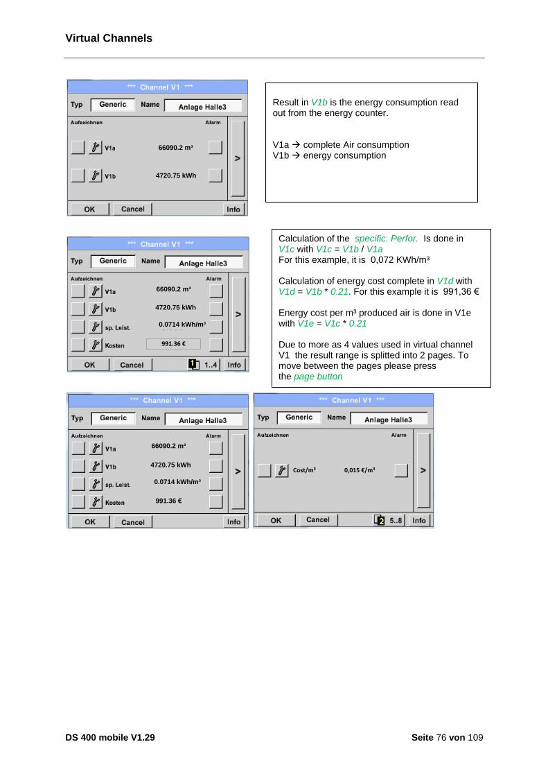
Virtual Channels
DS 400 mobile V1.29 Seite 76 von 109
66090.2 m³
4720.75 kWh
66090.2 m³
4720.75 kWh
0.0714 kWh/m³
991.36 €
66090.2 m³
4720.75 kWh
0.0714 kWh/m³
991.36 €
0,015 €/m³Cost/m³
Result in V1b is the energy consumption read out from the energy counter. V1a à complete Air consumption V1b à energy consumption
Calculation of the specific. Perfor. Is done in V1c with V1c = V1b / V1a For this example, it is 0,072 KWh/m³ Calculation of energy cost complete in V1d with V1d = V1b * 0.21. For this example it is 991,36 € Energy cost per m³ produced air is done in V1e with V1e = V1c * 0.21 Due to more as 4 values used in virtual channel V1 the result range is splitted into 2 pages. To move between the pages please press the page button
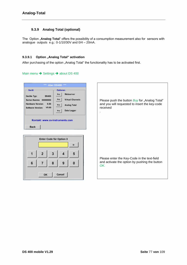
Analog-Total
DS 400 mobile V1.29 Seite 77 von 109
9.3.9 Analog Total (optional)
The Option „Analog Total“ offers the possibility of a consumption measurement also for sensors with analogue outputs e.g.: 0-1/10/30V and 0/4 – 20mA.
9.3.9.1 Option „Analog Total“ activation
After purchasing of the option „Analog Total“ the functionality has to be activated first. Main menu Settings about DS 400
V0.65
Buy
Buy
Buy
Buy
Cancel
Enter Code für Option 3
Please push the button Buy for „Analog Total“ and you will requested to insert the key-code received . Please enter the Key-Code in the text-field and activate the option by pushing the button OK.
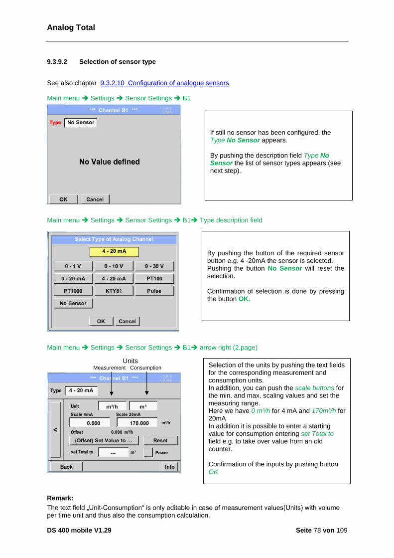
Analog Total
DS 400 mobile V1.29 Seite 78 von 109
9.3.9.2 Selection of sensor type
See also chapter 9.3.2.10 Configuration of analogue sensors Main menu Settings Sensor Settings B1
Main menu Settings Sensor Settings B1 Type description field
Main menu Settings Sensor Settings B1 arrow right (2.page)
Remark:
The text field „Unit-Consumption“ is only editable in case of measurement values(Units) with volume per time unit and thus also the consumption calculation.
If still no sensor has been configured, the Type No Sensor appears. By pushing the description field Type No Sensor the list of sensor types appears (see next step).
By pushing the button of the required sensor button e.g. 4 -20mA the sensor is selected. Pushing the button No Sensor will reset the selection. Confirmation of selection is done by pressing the button OK.
Selection of the units by pushing the text fields for the corresponding measurement and consumption units. In addition, you can push the scale buttons for the min. and max. scaling values and set the measuring range. Here we have 0 m³/h for 4 mA and 170m³/h for 20mA In addition it is possible to enter a starting value for consumption entering set Total to field e.g. to take over value from an old counter. Confirmation of the inputs by pushing button OK
Units Measurement Consumption Verbrauchsmenge
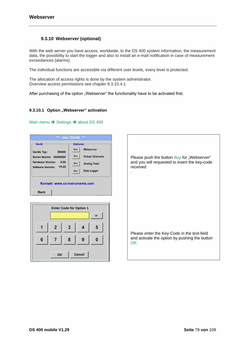
Webserver
DS 400 mobile V1.29 Seite 79 von 109
9.3.10 Webserver (optional)
With the web server you have access, worldwide, to the DS 400 system information, the measurement data, the possibility to start the logger and also to install an e-mail notification in case of measurement exceedances (alarms). The individual functions are accessible via different user levels, every level is protected. The allocation of access rights is done by the system administrator. Overview access permissions see chapter 9.3.10.4.1. After purchasing of the option „Webserver“ the functionality have to be activated first.
9.3.10.1 Option „Webserver“ activation
Main menu Settings about DS 400
V0.65
Buy
Buy
Buy
Buy
Cancel
Enter Code für Option 1
Please push the button Buy for „Webserver“ and you will requested to insert the key-code received . Please enter the Key-Code in the text-field and activate the option by pushing the button OK.
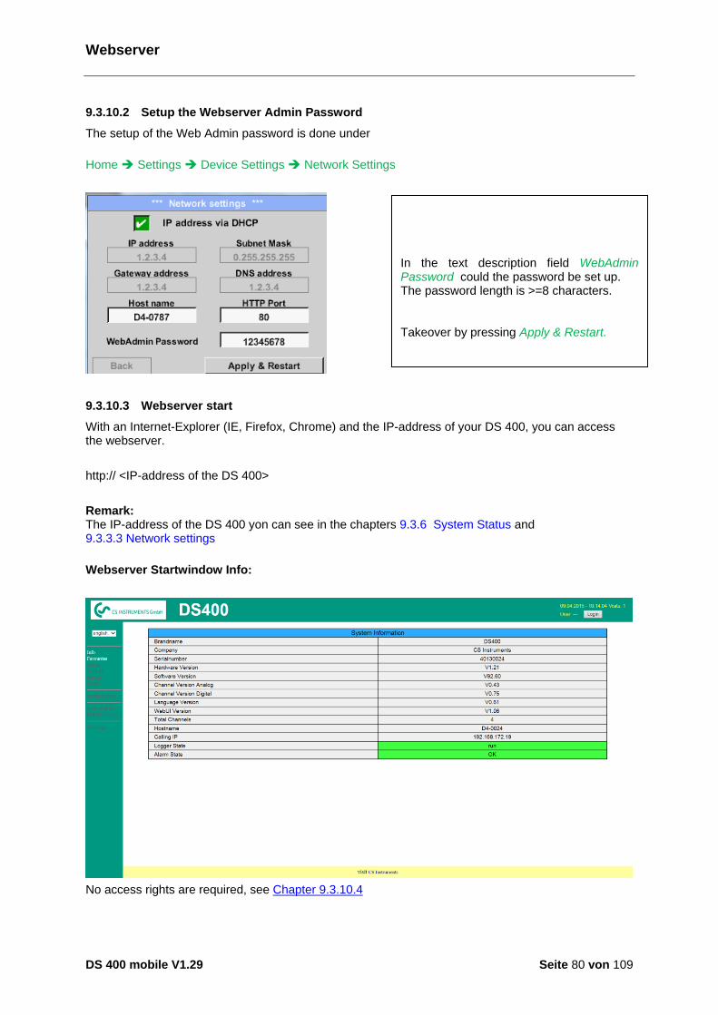
Webserver
DS 400 mobile V1.29 Seite 80 von 109
9.3.10.2 Setup the Webserver Admin Password
The setup of the Web Admin password is done under
Home Settings Device Settings Network Settings
9.3.10.3 Webserver start
With an Internet-Explorer (IE, Firefox, Chrome) and the IP-address of your DS 400, you can access the webserver.
http:// <IP-address of the DS 400>
Remark: The IP-address of the DS 400 yon can see in the chapters 9.3.6 System Status and 9.3.3.3 Network settings
Webserver Startwindow Info:
No access rights are required, see Chapter 9.3.10.4
In the text description field WebAdmin Password could the password be set up. The password length is >=8 characters. Takeover by pressing Apply & Restart. Spanisch Deutsch Englisch Übernahme durch betätigen von anwenden & Restart Übersetzung für Übernahme durch betätigen von anwenden & Restore Stattdessen übersetzen mit Übernahme durch betätigen von anwenden & Restart

Webserver
DS 400 mobile V1.29 Seite 81 von 109
9.3.10.4 Webserver assignment of rights (Administrator)
9.3.10.4.1 Accessrights Webserver
For individual functions, appropriate privileges are required, see table "access rights"
Rights Group
Info Status Actuals Chart MailonAlarm Settings User/Mail
w/o X
Guest X X X
User X X X X
Operator X X X X X
Admin X X X X X X Table Accessrights
9.3.10.5 Webserver Login
After pressing the Button « Login » following screen is visible.
Logion as Administrator with Username «admin» and the WebAdmin Password.
Setup of the WebAdmin Password see Chapterl 9.3.10.2
After starting as Administrator all the functions on the left side are activated.

Webserver
DS 400 mobile V1.29 Seite 82 von 109
9.3.10.6 New users and password
Selection of function « User/Passw. » (only for Administrators accessible)
With this function you are able to define the users with their corresponding accessrights.
Username : min. 4 characters; max. 12 characters
Password : min. 4 characters, max. 12 characters
Group : see access rights chapter 9.3.10.4
The inputs will be stored with « Submit »

Webserver
DS 400 mobile V1.29 Seite 83 von 109
9.3.10.7 Webserver E-Mail Configuration (Administrator)
Access of function « EMail » only for administrators
In case you are not logged in as administrator, please see chapter 9.3.10.5
At the first/ initial configuration there are no entries.
An existing mail account and those acessdata are needed for final mail configuratuion.
The settings will be stored by pressing « Submit »
A verification (correctness of your settings) could be done by sending a test mail.
Therefore please press the button« Test EMail setting»
Are all settings ok, a message, see left, will be displayed and a mail should be received by the defined recipients.
from: mail username to rcp 1: mail Address recipient 1 to rcp 2: mail Address recipient 2 Mail-Account Servername: Name of SMTP
Mail output server of your provider Mail Account User: mail Address of user Mail Account Password: user password of mail account
It is possible to define max. 2 mail recipients.
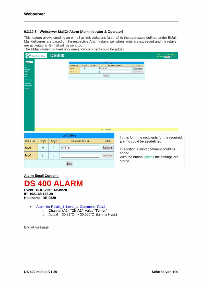
Webserver
DS 400 mobile V1.29 Seite 84 von 109
9.3.10.8 Webserver MailOnAlarm (Administrator & Operator)
This feature allows sending an e mail at limit violations (alarms) to the addresses defined under EMail. Mail deliveries are based on the respective Alarm relays, i.e. when limits are exceeded and the relays are activated an E-mail will be sent too. The EMail content is fixed only one short comment could be added.
Alarm Email Content:
DS 400 ALARM
Event: 15.01.2015 13:49:20 IP: 192.168.172.39 Hostname: DE-0529
Alarm for Relais_1 Level_1 Comment: Test1 o Channel (A2) "Ch-A2" Value "Temp." o Actual = 30.33°C > 30.000°C (Limit ± Hyst.)
End of message
In this form the recipients for the required alarms could be set/defined. In addition a short comment could be added. With the button Submit the settings are stored.
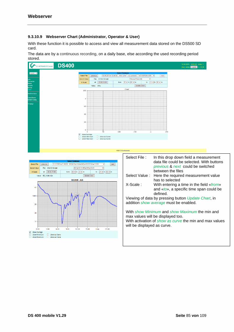
Webserver
DS 400 mobile V1.29 Seite 85 von 109
9.3.10.9 Webserver Chart (Administrator, Operator & User)
With these function it is possible to access and view all measurement data stored on the DS500 SD card.
The data are by a continuous recording, on a daily base, else according the used recording period stored.
Select File : In this drop down field a measurement data file could be selected. With buttons
previous & next could be switched between the files Select Value : Here the required measurement value has to selected X-Scale : With entering a time in the field «from» and «to», a specific time span could be
defined. Viewing of data by pressing button Update Chart, in addition show average must be enabled. With show Minimum and show Maximum the min and max values will be displayed too. With activation of show as curve the min and max values will be displayed as curve.

Webserver
DS 400 mobile V1.29 Seite 86 von 109
9.3.10.10 Webserver Screen
Herewith it is possible to get a screen copy of the DS400 for Home menu, Chart/RT, Channels, Realtime values, Alarm and Settings (System status, about DS 400). Remark : Any selection change done through the webserver is transferred to the DS 400 too. With simultaneous access to the DS 400 by webserver and an operator direct at the DS400 the operator has priority. By simultaneous web access priority is according to access rights.
Screen Chart/RT
Screen Channels
Selection of the screens
Realtime) Screen Realtime Alarm Screen Alarm Settings Screen Settings
is done analogy to above
Timescale : The required timespan could be selected
Active Plot : Herewith could one of the defined curves selected where for which the Y-scale will be displayed. A double click will switch on / switch off the corresponding curve
Both function are analogue DS400. By pressing Home the screen is going back to the main menu.
Select channels: Selection of single channel .
Page: If the sensor has more as 4
values, by pressing this button you can switch to 2.page. .
HW/VirtCh. : Switch to Virtual Channel Settings are analogy to DS 400 By pressing Back the screen is going back to the main menu.
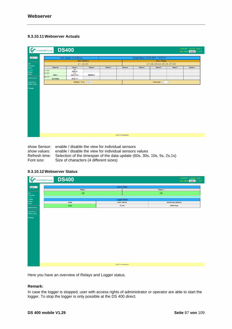
Webserver
DS 400 mobile V1.29 Seite 87 von 109
9.3.10.11 Webserver Actuals
show Sensor: enable / disable the view for individual sensors show values: enable / disable the view for individual sensors values Refresh time: Selection of the timespan of the data update (60s, 30s, 10s, 5s, 2s,1s) Font size: Size of characters (4 different sizes)
9.3.10.12 Webserver Status
Here you have an overview of Relays and Logger status.
Remark:
In case the logger is stopped, user with access rights of administrator or operator are able to start the logger. To stop the logger is only possible at the DS 400 direct.
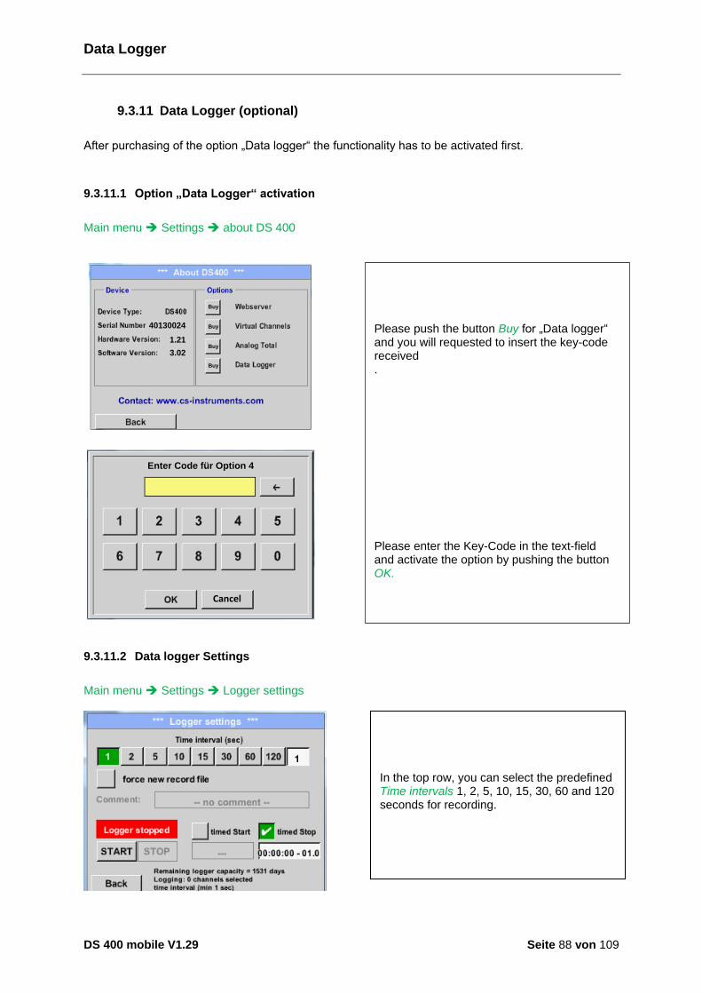
Data Logger
DS 400 mobile V1.29 Seite 88 von 109
9.3.11 Data Logger (optional)
After purchasing of the option „Data logger“ the functionality has to be activated first.
9.3.11.1 Option „Data Logger“ activation
Main menu Settings about DS 400
1.21
3.02
40130024
Buy
Buy
Buy
Buy
Cancel
Enter Code für Option 4
9.3.11.2 Data logger Settings
Main menu Settings Logger settings
In the top row, you can select the predefined Time intervals 1, 2, 5, 10, 15, 30, 60 and 120 seconds for recording.
Please push the button Buy for „Data logger“ and you will requested to insert the key-code received . Please enter the Key-Code in the text-field and activate the option by pushing the button OK.
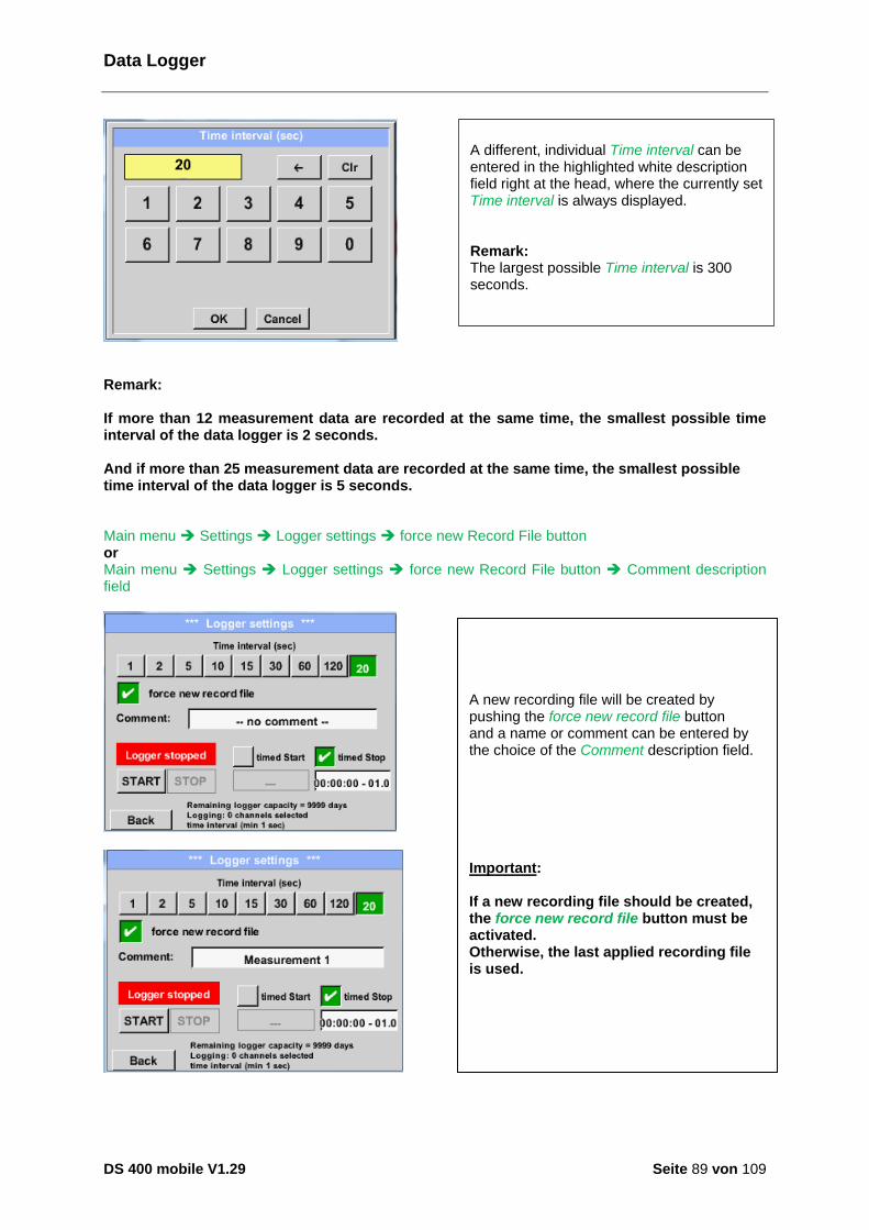
Data Logger
DS 400 mobile V1.29 Seite 89 von 109
Remark: If more than 12 measurement data are recorded at the same time, the smallest possible time interval of the data logger is 2 seconds. And if more than 25 measurement data are recorded at the same time, the smallest possible time interval of the data logger is 5 seconds. Main menu Settings Logger settings force new Record File button or Main menu Settings Logger settings force new Record File button Comment description field
A new recording file will be created by pushing the force new record file button and a name or comment can be entered by the choice of the Comment description field. Important: If a new recording file should be created, the force new record file button must be activated. Otherwise, the last applied recording file is used.
A different, individual Time interval can be entered in the highlighted white description field right at the head, where the currently set Time interval is always displayed. Remark: The largest possible Time interval is 300 seconds.

Data Logger
DS 400 mobile V1.29 Seite 90 von 109
Main menu Settings Logger settings timed Start button
Main menu Settings Logger settings timed Stop button
Main menu Settings Logger settings timed Start button/timed Stop button Date/Time description field
By pushing the timed Start button and then the date/time description field below, the date and the start time can be set for a data logger recording. Remark: If the start time is activated, it will automatically be set at the current time plus a minute.
By pushing the timed Stop button and then the date/time description field below, the date and the stop time can be set for a data logger recording. Remark: If the stop time activated, it will automatically be set to the current time plus an hour.
After pushing the date/time description field a window will appear where the yellow marked area of the time or date can always be set and changed.
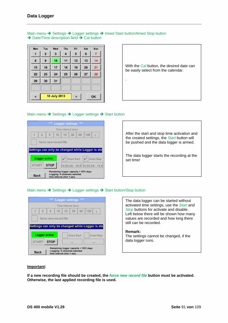
Data Logger
DS 400 mobile V1.29 Seite 91 von 109
Main menu Settings Logger settings timed Start button/timed Stop button Date/Time description field Cal button
Main menu Settings Logger settings Start button
Main menu Settings Logger settings Start button/Stop button
Important: If a new recording file should be created, the force new record file button must be activated. Otherwise, the last applied recording file is used.
After the start and stop time activation and the created settings, the Start button will be pushed and the data logger is armed. The data logger starts the recording at the set time!
The data logger can be started without activated time settings, use the Start and Stop buttons for activate and disable. Left below there will be shown how many values are recorded and how long there still can be recorded. Remark: The settings cannot be changed, if the data logger runs.
With the Cal button, the desired date can be easily select from the calendar. .

Chart
DS 400 mobile V1.29 Seite 92 von 109
9.4 Chart
Main menu Chart Attention: In the Chart there can be represented only records that have already finished! Current records can be seen in Chart/Real time values. (See chapter 12.4 Chart/Real time values)
Zoom and scroll options in the time domain of the Chart:
Additional zooming and scrolling options in Chart and Chart/Real time values:
Running measurement, there are no values represented!
Maximal an entire day can be represented (24h).
The smallest possible range is represented, depending on the time interval of the recording.
time later
bigger period of time
time earlier
smaller period of time
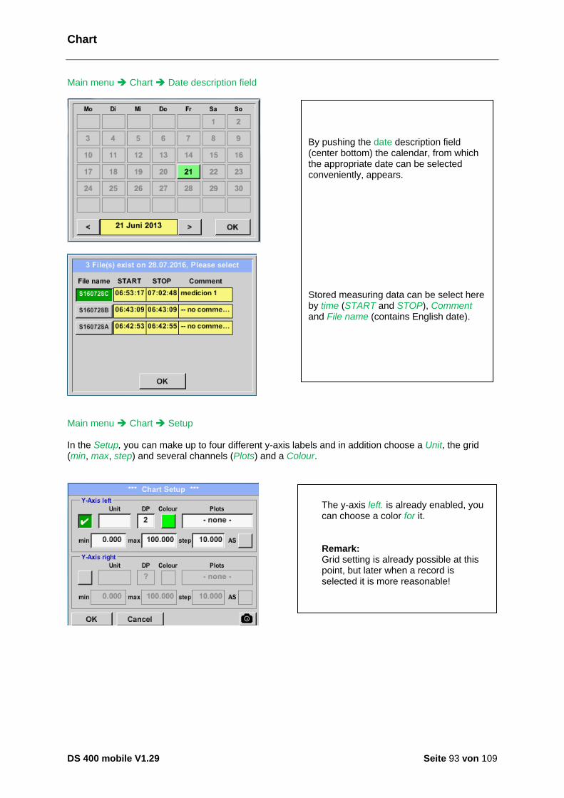
Chart
DS 400 mobile V1.29 Seite 93 von 109
Main menu Chart Date description field
Main menu Chart Setup In the Setup, you can make up to four different y-axis labels and in addition choose a Unit, the grid (min, max, step) and several channels (Plots) and a Colour.
By pushing the date description field (center bottom) the calendar, from which the appropriate date can be selected conveniently, appears. Stored measuring data can be select here by time (START and STOP), Comment and File name (contains English date).
The y-axis left. is already enabled, you can choose a color for it. Remark: Grid setting is already possible at this point, but later when a record is selected it is more reasonable!
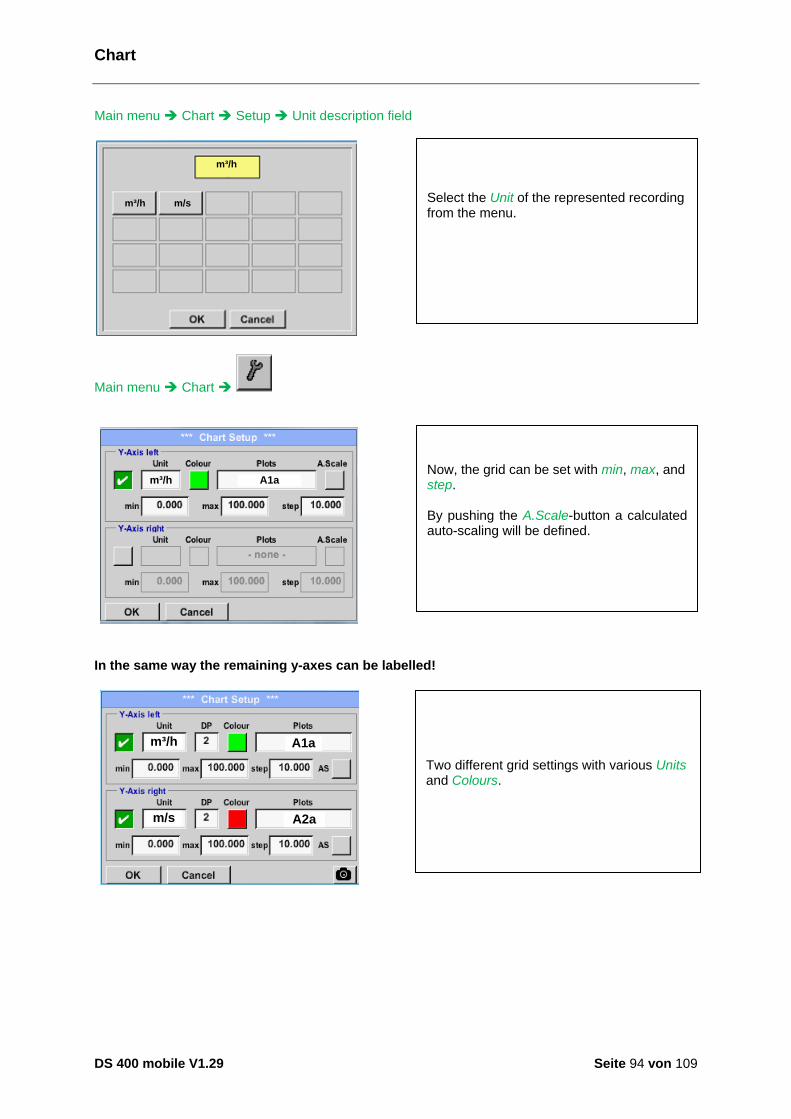
Chart
DS 400 mobile V1.29 Seite 94 von 109
Main menu Chart Setup Unit description field
m³/h m/s
m³/h
Main menu Chart
m³/h A1a
In the same way the remaining y-axes can be labelled!
m/s
m³/h A1a
A2a
Two different grid settings with various Units and Colours.
Select the Unit of the represented recording from the menu.
Now, the grid can be set with min, max, and step. By pushing the A.Scale-button a calculated auto-scaling will be defined.
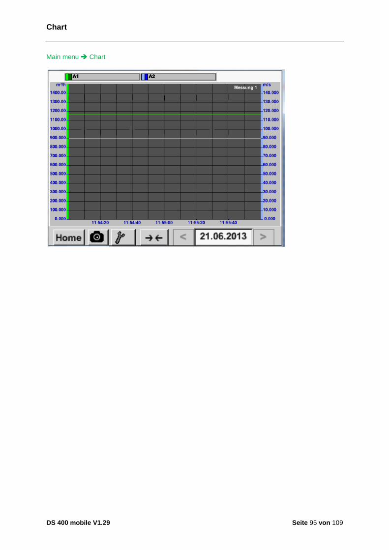
Chart
DS 400 mobile V1.29 Seite 95 von 109
Main menu Chart
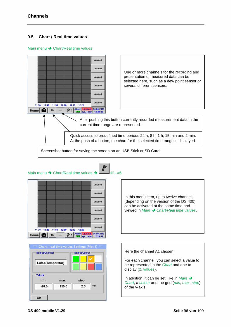
Channels
DS 400 mobile V1.29 Seite 96 von 109
9.5 Chart / Real time values
Main menu Chart/Real time values
Main menu Chart/Real time values #1- #6
4°C
One or more channels for the recording and presentation of measured data can be selected here, such as a dew point sensor or several different sensors.
In this menu item, up to twelve channels (depending on the version of the DS 400) can be activated at the same time and viewed in Main Chart/Real time values.
Here the channel A1 chosen. For each channel, you can select a value to be represented in the Chart and one to display (2. values). In addition, it can be set, like in Main Chart, a colour and the grid (min, max, step) of the y-axis.
Quick access to predefined time periods 24 h, 8 h, 1 h, 15 min and 2 min.
At the push of a button, the chart for the selected time range is displayed.
After pushing this button currently recorded measurement data in the
current time range are represented.
.
Screenshot button for saving the screen on an USB Stick or SD Card.

Chart / Real time values
DS 400 mobile V1.29 Seite 97 von 109
Main menu Chart/Real time values
1350 m³/h
m³/h
In the same way the remaining setups can be set!
Channel A1: Elected the flow as Chart . If several channels are logged, all charts will be displayed, but there is only the y-axis of the selected channel visible. If there is no grid entered in the setup, min will be 0, max 100 and step 10

Channels
DS 400 mobile V1.29 Seite 98 von 109
9.6 Channels
Main menu Channels
Main menu Channels A1
m³/h
m³
m/s
°C
0.00
4589
0.00
25.70
Flow
Comsumpt.
Velocity
Temp.
Halle 1
The overview of Real time values shows the current measured values of all connected sensors. Exceeds or falls below the set alarm limits, the respective measured value flashes yellow (alarm 1) or red (alarm 2).
Each channel can be selected and the settings viewed and checked, but no changes can be made here. Remark: Please, make changes in the Settings!
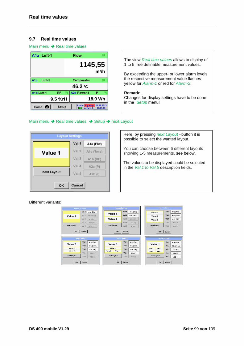
Real time values
DS 400 mobile V1.29 Seite 99 von 109
9.7 Real time values
Main menu Real time values
1145,55 m³/h
-9.5 %rH 18.9 Wh
Main menu Real time values Setup next Layout
Different variants:
The view Real time values allows to display of 1 to 5 free definable measurement values. By exceeding the upper- or lower alarm levels the respective measurement value flashes yellow for Alarm-1 or red for Alarm-2. Remark: Changes for display settings have to be done in the Setup menu!
Here, by pressing next Layout –button it is possible to select the wanted layout. You can choose between 6 different layouts showing 1-5 measurements. see below. The values to be displayed could be selected in the Val.1 to Val.5 description fields.
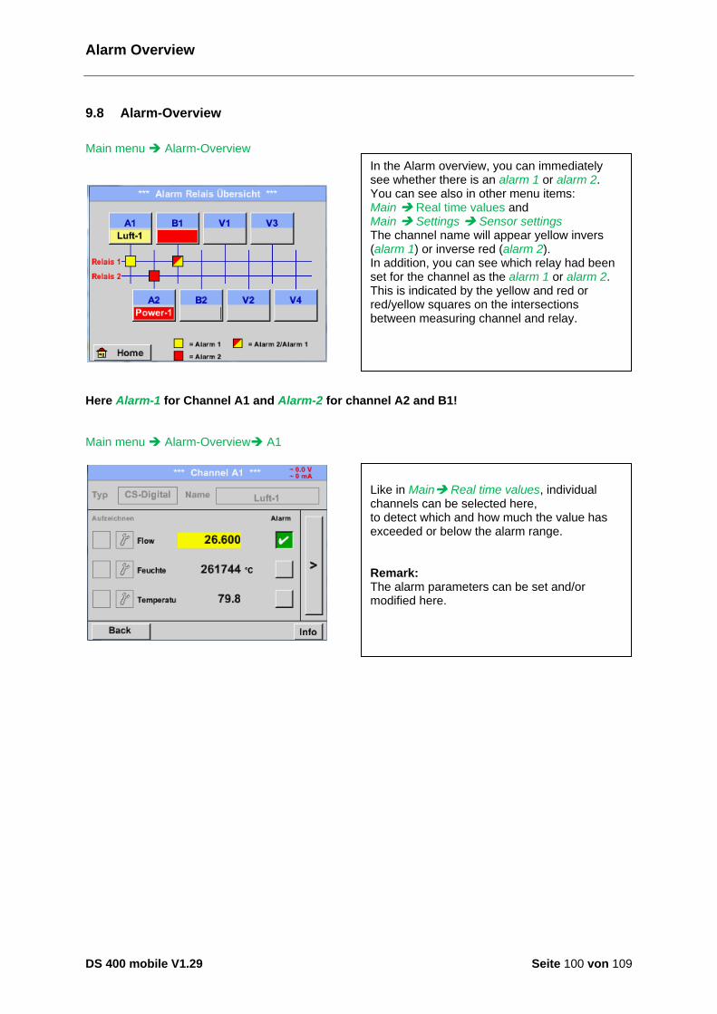
Alarm Overview
DS 400 mobile V1.29 Seite 100 von 109
9.8 Alarm-Overview
Main menu Alarm-Overview
Here Alarm-1 for Channel A1 and Alarm-2 for channel A2 and B1! Main menu Alarm-Overview A1
In the Alarm overview, you can immediately see whether there is an alarm 1 or alarm 2. You can see also in other menu items: Main Real time values and Main Settings Sensor settings The channel name will appear yellow invers (alarm 1) or inverse red (alarm 2). In addition, you can see which relay had been set for the channel as the alarm 1 or alarm 2. This is indicated by the yellow and red or red/yellow squares on the intersections between measuring channel and relay.
Wie bei Hauptmenü Channels können auch hier einzelne Kanäle ausgewählt werden. In der Alarm-Übersicht ist schnell zu erkennen, welcher Messwert den Alarmbereich überschritten bzw. unterschritten hat. Hinweis: Hier können auch die Alarmparameter gesetzt und/oder verändert werden.
Like in Main Real time values, individual channels can be selected here, to detect which and how much the value has exceeded or below the alarm range. Remark: The alarm parameters can be set and/or modified here.
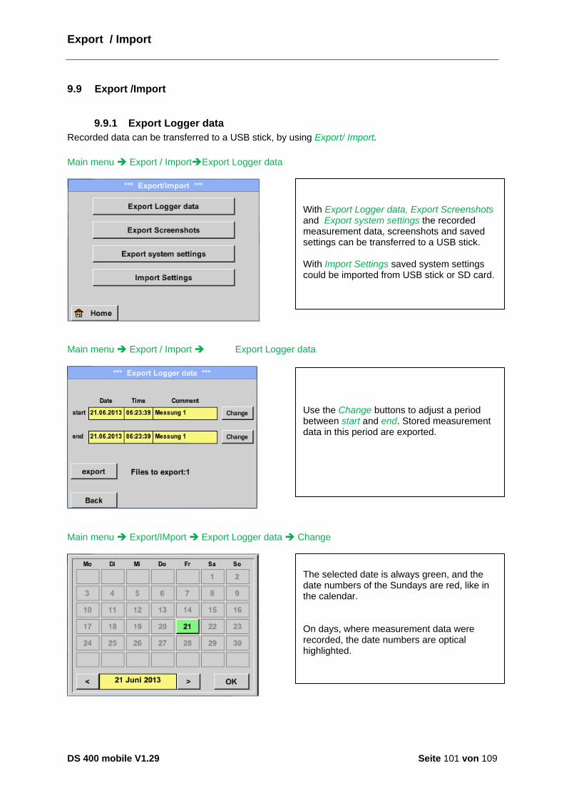
Export / Import
DS 400 mobile V1.29 Seite 101 von 109
9.9 Export /Import
9.9.1 Export Logger data
Recorded data can be transferred to a USB stick, by using Export/ Import.
Main menu Export / ImportExport Logger data
Main menu Export / Import Export Logger data
Main menu Export/IMport Export Logger data Change
With Export Logger data, Export Screenshots and Export system settings the recorded measurement data, screenshots and saved settings can be transferred to a USB stick. With Import Settings saved system settings could be imported from USB stick or SD card.
Use the Change buttons to adjust a period between start and end. Stored measurement data in this period are exported.
The selected date is always green, and the date numbers of the Sundays are red, like in the calendar. On days, where measurement data were recorded, the date numbers are optical highlighted.

Export / Import
DS 400 mobile V1.29 Seite 102 von 109
Main menu Export/Import Export Logger data export The measurement data of the selected period are exported to a USB stick.
If there have been recorded several measurements on the same date, they appear after the date selection with OK. Now a recording can be selected comfortable.

Export / Import
DS 400 mobile V1.29 Seite 103 von 109
9.9.2 Export System Settings
Using this function, all existing device- and sensor settings can be exported to a USB stick or SD-card. All sensor settings including recording-, alarm-, measurement resolution-, graphics-, current values and naming-definitions are taken over.
Main menu Export/Import Export system settings
All already saved system settings will be displayed, depending on the location USB Stick or SD-Card... Location/ path is: DEV0002/Settings In case an existing file will be selected the content will be overwritten with the new settings after confirming with OK . New File storage: Select the location for storing by pressing the button USB or SDCard. By choosing button new file a menu for inserting/defining the filename appears. The file name length is limited to 8 chars. File save/confirm with: OK OK
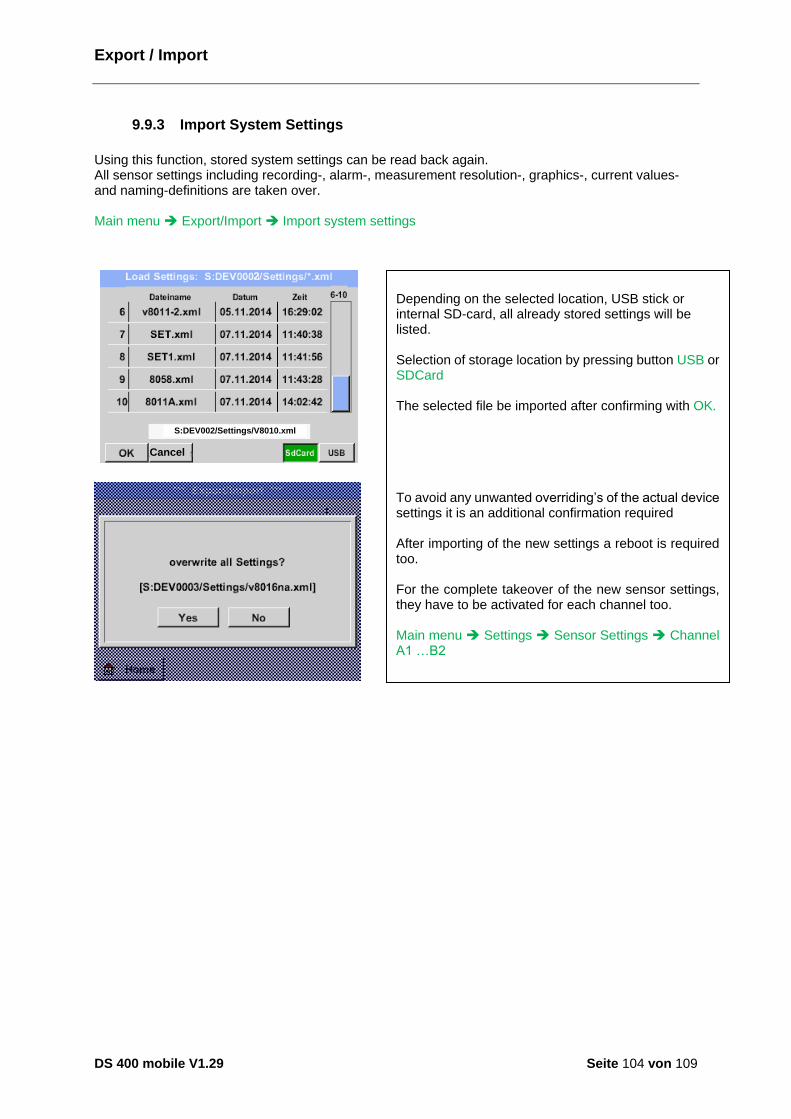
Export / Import
DS 400 mobile V1.29 Seite 104 von 109
9.9.3 Import System Settings
Using this function, stored system settings can be read back again. All sensor settings including recording-, alarm-, measurement resolution-, graphics-, current values- and naming-definitions are taken over. Main menu Export/Import Import system settings
2
Cancel
S:DEV002/Settings/V8010.xml
Depending on the selected location, USB stick or internal SD-card, all already stored settings will be listed. Selection of storage location by pressing button USB or SDCard The selected file be imported after confirming with OK. To avoid any unwanted overriding’s of the actual device settings it is an additional confirmation required After importing of the new settings a reboot is required too. For the complete takeover of the new sensor settings, they have to be activated for each channel too. Main menu Settings Sensor Settings Channel A1 …B2
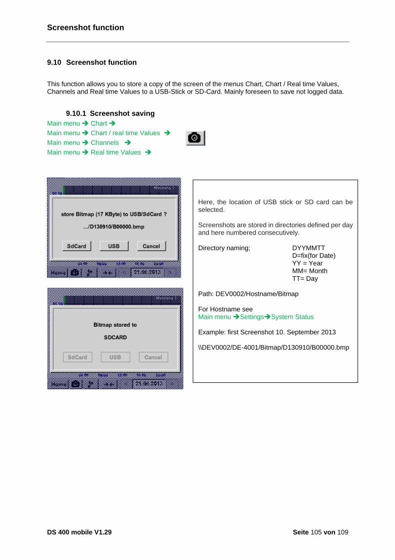
Screenshot function
DS 400 mobile V1.29 Seite 105 von 109
9.10 Screenshot function
This function allows you to store a copy of the screen of the menus Chart, Chart / Real time Values, Channels and Real time Values to a USB-Stick or SD-Card. Mainly foreseen to save not logged data.
9.10.1 Screenshot saving
Main menu Chart
Main menu Chart / real time Values
Main menu Channels
Main menu Real time Values
Here, the location of USB stick or SD card can be selected. Screenshots are stored in directories defined per day and here numbered consecutively. Directory naming; DYYMMTT D=fix(for Date)
YY = Year MM= Month TT= Day Path: DEV0002/Hostname/Bitmap For Hostname see Main menu SettingsSystem Status Example: first Screenshot 10. September 2013 \\DEV0002/DE-4001/Bitmap/D130910/B00000.bmp

Export / Import
DS 400 mobile V1.29 Seite 106 von 109
9.10.2 Screenshots export
The screenshots stored on the SD card can be exported to a USB stick
Main menu Export / Import
Main menu Export / Import Export Screenshots
5
83
Main menu Export / Import Export Screenshots Change
With Export Screenshots the recorded screenshots data can be transferred to a USB stick.
Use the Change buttons to adjust a period between start and end. Stored bitmaps data in this period are exported.
The selected date is always green, and the date numbers of the Sundays are red, like in the calendar. On days, where measurement data were recorded, the date numbers are optical highlighted.

Export / Import
DS 400 mobile V1.29 Seite 107 von 109
Main menu Export / Import Export Screenshots Export
5
83
The screenshots of the selected period are exported to a USB stick.
Cleaning
DS 400 mobile V1.29 Seite 108 von 109
10 Cleaning
Note:
The DS 400 has a cleaning-function which protects the display against unintentional operation in the event of cleaning measures. Please refer to Chapter 9.3.5 for further information.
Cleaning of the DS 400 must be undertaken using a slightly damp (not wet) cotton cloth or one-way wipe, and mild, commercially available cleaner/soap.
For decontamination, spray the cleaner on an unused cotton cloth or one-way wipe, and wipe the component comprehensively. Perform the final drying with a clean cloth or by air drying.
In addition, the local hygiene provisions need to be observed.
Warning!
Damage possible!
A too high degree of humidity and hard and pointed objects, as well as aggressive cleaners, cause damage to the data logger and to the integrated electronic components.
Measures
• Never clean with a soaked cloth.
• Do not use aggressive cleaners.
• Do not use pointed or hard objects for cleaning.
DS 400 mobile V1.29 Seite 109 von 109