inst99-7503 - installer
TRANSCRIPT

INSTALLATION INSTRUCTIONS FOR PART 99-7507
Phillips Screwdriver • Small Flat Blade Screwdriver • Socket Wrench
1-800-221-0932 www.metraonline.com
KIT FEATURES
© COPYRIGHT 2007-2009 METRA ELECTRONICS CORPORATION
• DIN Head Unit Provision• ISO DIN Head Unit Provision
A) Radio/Climate Control Housing Assembly • B) ISO Brackets • C) ISO Trim Plate • D) Harnesses
KIT COMPONENTS
TOOLS REQUIRED:
99-7507
A
APPLICATIONS
Mazda 6 2006-2007
B C D
Dash Disassembly . . . . . . . . . . . . . . . . . . . . . . . . . . . . . . . . . . . 1-5Electronic Climate Control . . . . . . . . . . . . . . . . . . . . . . . . . 1-2Manual Climate Control . . . . . . . . . . . . . . . . . . . . . . . . . . . . 3-5
Kit Assembly . . . . . . . . . . . . . . . . . . . . . . . . . . . . . . . . . . . . . .6-8Electronic Climate Control . . . . . . . . . . . . . . . . . . . . . . . . . . . . 6Manual Climate Control . . . . . . . . . . . . . . . . . . . . . . . . . . . . 7-8
Felt Tape Application . . . . . . . . . . . . . . . . . . . . . . . . . . . . . . . . . . 9
Display Customization . . . . . . . . . . . . . . . . . . . . . . . . . . . . . . . . 10
Final Wiring and Assembly. . . . . . . . . . . . . . . . . . . . . . . . . . .11,12
TABLE OF CONTENTS
99-7507
KNOWLEDGE IS POWEREnhance your installation and fabrication skillsby enrolling in the most recognized and respected mobile electronics school in our industry.Log onto www.installerinstitute.comor call 800-354-6782 for more information and take steps toward a better tomorrow.
99-7507
1
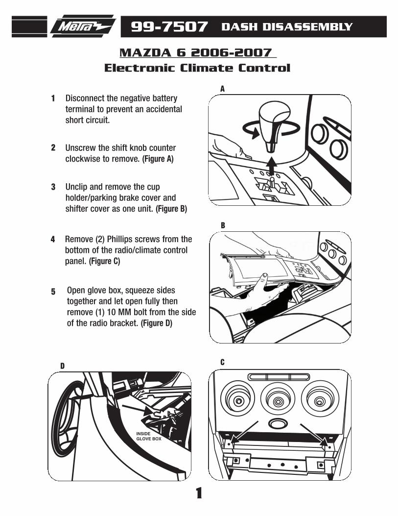
Disconnect the negative battery terminal to prevent an accidentalshort circuit.
1
Unscrew the shift knob counterclockwise to remove. (Figure A)
2
MAZDA 6 2006-2007
Unclip and remove the cupholder/parking brake cover andshifter cover as one unit. (Figure B)
3
Remove (2) Phillips screws from thebottom of the radio/climate controlpanel. (Figure C)
4
DASH DISASSEMBLY
A
B
C
INSIDEGLOVE BOX
D
Open glove box, squeeze sidestogether and let open fully thenremove (1) 10 MM bolt from the sideof the radio bracket. (Figure D)
5
Electronic Climate Control
99-7507 DASH DISASSEMBLY
MAZDA 6 2006-2007Electronic Climate Control
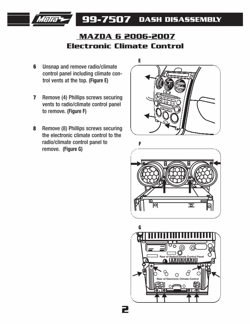
Unsnap and remove radio/climatecontrol panel including climate con-trol vents at the top. (Figure E)
Remove (4) Phillips screws securingvents to radio/climate control panelto remove. (Figure F)
7
Remove (8) Phillips screws securingthe electronic climate control to theradio/climate control panel toremove. (Figure G)
8
6
F
Rear of Electronic Climate Control
Rear of Radio/Climate Control Panel
G
2
E

3
Disconnect the negative battery terminal to prevent an accidentalshort circuit.
1
Unscrew the shift knob counterclockwise to remove. (Figure A)
2
Remove (2) Phillips screws from thebottom of the radio/climate controlpanel. (Figure C)
4
Pull the climate control knobs offand remove (2) Phillips screws frombehind knobs. (Figure D)
5
Unclip and remove the cupholder/parking brake cover andshifter cover as one unit. (Figure B)
3
MAZDA 6 2006-2007Manual Climate Control
A
B
C
A/C
D
99-7507 DASH DISASSEMBLY
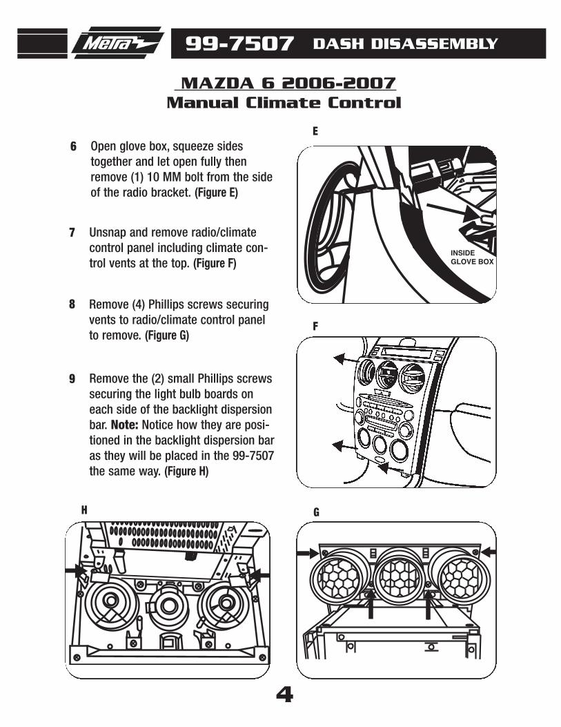
Open glove box, squeeze sidestogether and let open fully thenremove (1) 10 MM bolt from the sideof the radio bracket. (Figure E)
6
INSIDEGLOVE BOX
E
4
99-7507 DASH DISASSEMBLY
MAZDA 6 2006-2007Manual Climate Control
Unsnap and remove radio/climatecontrol panel including climate con-trol vents at the top. (Figure F)
7
F
Remove (4) Phillips screws securingvents to radio/climate control panelto remove. (Figure G)
8
G
Remove the (2) small Phillips screwssecuring the light bulb boards oneach side of the backlight dispersionbar. Note: Notice how they are posi-tioned in the backlight dispersion baras they will be placed in the 99-7507the same way. (Figure H)
9
H
5
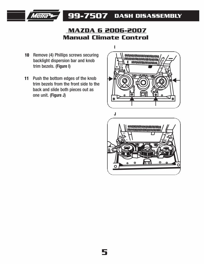
Remove (4) Phillips screws securingbacklight dispersion bar and knobtrim bezels. (Figure I)
10
Push the bottom edges of the knobtrim bezels from the front side to theback and slide both pieces out asone unit. (Figure J)
11
I
J
99-7507 DASH DISASSEMBLY
MAZDA 6 2006-2007Manual Climate Control
6
99-7507
MAZDA 6 2006-2007Electronic Climate Control
KIT ASSEMBLY
A
REAR VIEW OF ELECTRONIC CLIMATE CONTROL
B
D
C
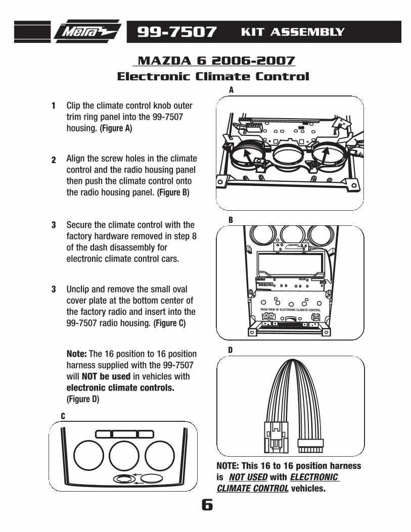
Clip the climate control knob outertrim ring panel into the 99-7507 housing. (Figure A)
Align the screw holes in the climatecontrol and the radio housing panelthen push the climate control ontothe radio housing panel. (Figure B)
Secure the climate control with thefactory hardware removed in step 8of the dash disassembly forelectronic climate control cars.
1
2
3
Note: The 16 position to 16 positionharness supplied with the 99-7507will NOT be used in vehicles withelectronic climate controls.(Figure D)
Unclip and remove the small ovalcover plate at the bottom center ofthe factory radio and insert into the99-7507 radio housing. (Figure C)
3
NOTE: This 16 to 16 position harnessis NOT USED with ELECTRONIC CLIMATE CONTROL vehicles.
Manual Climate Control
99-7507 KIT ASSEMBLY
MAZDA 6 2006-2007
7
A
ASSEMBLED
B
INSTALLED
C
D
E
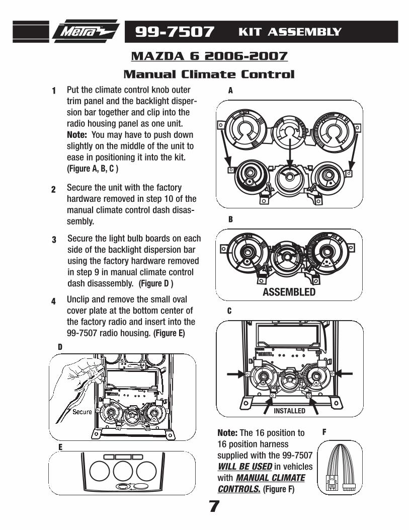
Put the climate control knob outertrim panel and the backlight disper-sion bar together and clip into theradio housing panel as one unit.Note: You may have to push downslightly on the middle of the unit toease in positioning it into the kit.(Figure A, B, C )
1
2
3
Secure the unit with the factoryhardware removed in step 10 of themanual climate control dash disas-sembly.
4 Unclip and remove the small ovalcover plate at the bottom center ofthe factory radio and insert into the99-7507 radio housing. (Figure E)
Secure the light bulb boards on eachside of the backlight dispersion barusing the factory hardware removedin step 9 in manual climate controldash disassembly. (Figure D )
Note: The 16 position to16 position harness supplied with the 99-7507WILL BE USED in vehicleswith MANUAL CLIMATECONTROLS. (Figure F)
F

8
Slide the DIN cage into the RadioHousing and secure by bending themetal locking tabs down. (Figure A)
1
Mount the ISO Brackets to the headunit with the screws supplied withthe unit. (Figure A)
1
A
A
B
Slide the aftermarket head unit intothe DIN cage until secure. (Figure B)
2
Slide the head unit into the radioopening until the side clips engage.(Figure B)
2
Snap the Trim plate into the RadioHousing. (Figure B)
3
DIN HEAD UNIT PROVISION
ISO DIN HEAD UNIT PROVISION
B
Snap the Trim plate into the RadioHousing. (Figure B)
3
99-7507 KIT ASSEMBLY

9
FELT TAPE APPLICATION
99-7507
Apply To Rear Of Both Sides
Note: Due to differences in factory tolerances you may need to apply the provided felt tape to theedge of the 99-7507 radio housing to relieve backlight bleed through.
1. Looking at edge of radio housing apply felt tape to inner edge (toward back of kit). If it is posi-tioned to closely to the outer edge you may be able to see it once it is in the dash.

10
DISPLAY CUSTOMIZATION
99-7507
CLOCK
SET
DIMMER
AMB
1. Press and hold the AMB button on the factory display for 5 seconds then release the button. Thefirst character will be highlighted. Settings will begin with the first character location. Use the AMBbutton to select the desired character then wait. The next character will be highlighted. Press andrelease to set that character, and keep going until the text is to your liking. There are 10 availablecharacter locations.
2. Once the desired text is entered press and hold the AMB button for greater than 5 seconds thenrelease and the display will read “Text Saved.”
11
FINAL WIRING and ASSEMBLY
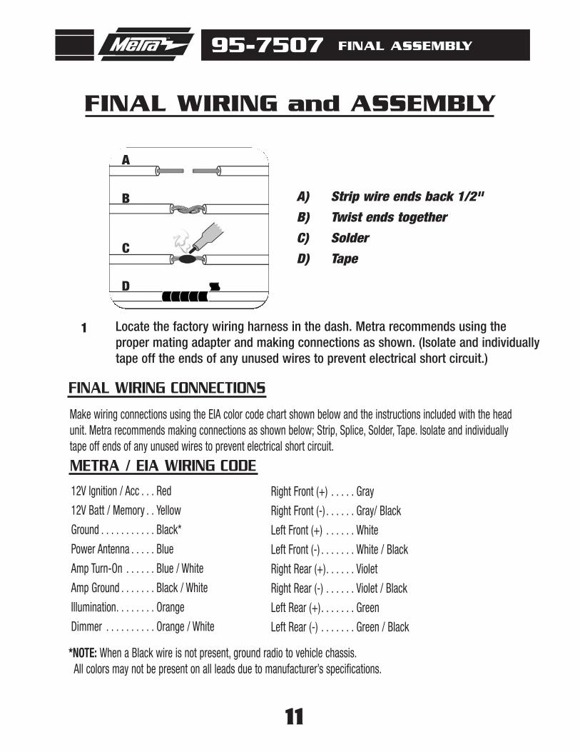
Make wiring connections using the EIA color code chart shown below and the instructions included with the headunit. Metra recommends making connections as shown below; Strip, Splice, Solder, Tape. Isolate and individuallytape off ends of any unused wires to prevent electrical short circuit.
FINAL WIRING CONNECTIONS
95-7507 FINAL ASSEMBLY
12V Ignition / Acc . . . Red
12V Batt / Memory . . Yellow
Ground . . . . . . . . . . . Black*
Power Antenna . . . . . Blue
Amp Turn-On . . . . . . Blue / White
Amp Ground . . . . . . . Black / White
Illumination. . . . . . . . Orange
Dimmer . . . . . . . . . . Orange / White
Right Front (+) . . . . . Gray
Right Front (-) . . . . . . Gray/ Black
Left Front (+) . . . . . . White
Left Front (-) . . . . . . . White / Black
Right Rear (+). . . . . . Violet
Right Rear (-) . . . . . . Violet / Black
Left Rear (+). . . . . . . Green
Left Rear (-) . . . . . . . Green / Black
METRA / EIA WIRING CODE
*NOTE: When a Black wire is not present, ground radio to vehicle chassis.All colors may not be present on all leads due to manufacturer’s specifications.
1 Locate the factory wiring harness in the dash. Metra recommends using the proper mating adapter and making connections as shown. (Isolate and individuallytape off the ends of any unused wires to prevent electrical short circuit.)
A
A) Strip wire ends back 1/2"
B) Twist ends together
C) Solder
D) Tape
B
C
D
12
2
3
4
5
6
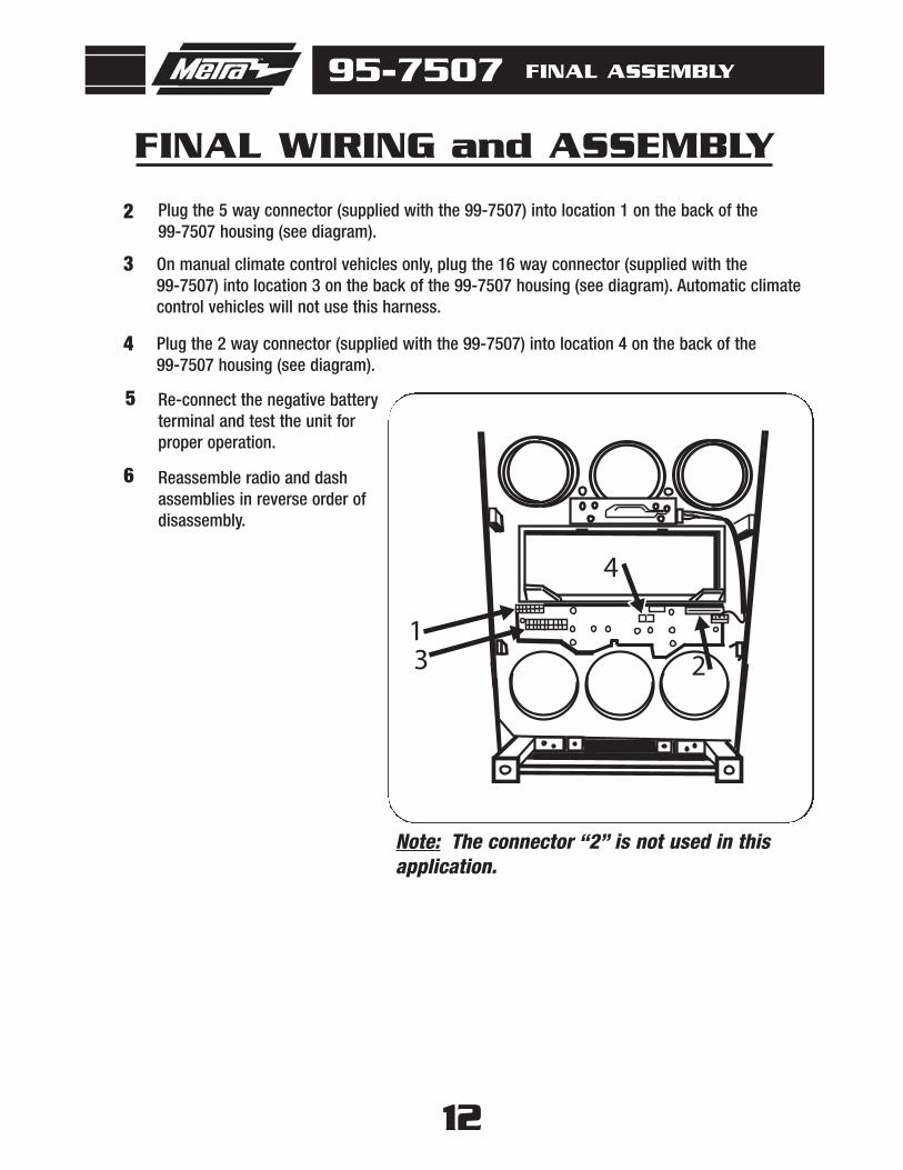
Plug the 5 way connector (supplied with the 99-7507) into location 1 on the back of the 99-7507 housing (see diagram).
On manual climate control vehicles only, plug the 16 way connector (supplied with the 99-7507) into location 3 on the back of the 99-7507 housing (see diagram). Automatic climatecontrol vehicles will not use this harness.
Reassemble radio and dashassemblies in reverse order of disassembly.
Plug the 2 way connector (supplied with the 99-7507) into location 4 on the back of the 99-7507 housing (see diagram).
13 2
4
Re-connect the negative battery terminal and test the unit for proper operation.
95-7507 FINAL ASSEMBLY
FINAL WIRING and ASSEMBLY
Note: The connector “2” is not used in thisapplication.

13
NOTES
99-7507
INST997507
1-800-221-0932 www.metraonline.comREV. 07/16/09 © COPYRIGHT 2007-2009 METRA ELECTRONICS CORPORATION INST99-7507