metraonline.commetraonline.com/files/products/inst99-7809b_web.pdf · kit feaur...
TRANSCRIPT

CAUTION! All accessories, switches, climate controls panels, and especially air bag indicator lights must be connected before cycling the ignition. Also, do not remove the factory radio with the key in the on position, or while the vehicle is running.
The World’s best kits.® MetraOnline.com © COPYRIGHT 2018 METRA ELECTRONICS CORPORATION REV. 4/30/18 INST99-7809B
I N S TA L L AT I O N I N S T R U C T I O N S99-7809B
KIT FEATURES• ISODINradioprovisionwithpocket• ISODDINradioprovision• Paintedmatteblack
KIT COMPONENTS•A)Radiotrimpanel•B)Radiobrackets•C)Climatecontrol•D)Pocket•E)(8)#8x3/8”Phillipsscrews•F)(2)#10x3/4”Phillipsscrews•G)(2)#8Speedclips•H)(8)PC-7871BPanelclips•Wireharness(notshown)
TOOLS REQUIRED•Panelremovaltool•Phillipsscrewdriver•5/16”socketwrench•Rotarycuttingtool
TABLE OF CONTENTS
DashDisassembly.............................................. 2-4KitAssembly–ISODINradioprovisionwithpocket.................5–ISODDINradioprovision....................................6WiringInstructions................................................ 7KitProgramming...................................................8
WIRING & ANTENNA CONNECTIONS
WiringHarness:IncludedAntennaAdapter:NotrequiredSteeringwheelcontrolinterface:ASWC-1 (soldseparately)
AcuraTSX2004-2008
A B C D E
F G H
1.800.221.0932 | MetraOnline.com2
DASH DISASSEMBLY
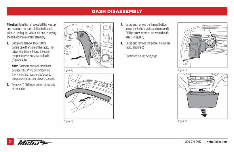
Attention! Turnthefanspeedallthewayup,andthenturntherecirculationbuttonoff,priortoturningthevehicleoffandremovingtheradio/climatecontrolassembly.
1. Unclipandremovethe(2)trimpanelsoneithersideoftheradio.Thedriversidetrimwillhavethecabintemperaturesensorattachedtoit(FiguresA,B)
Note:Complete removal should not be necessary. If you do remove this trim it must be reconnected prior to programming the new climate controls.
2. Remove(1)Phillipsscrewoneithersideoftheradio.
3. Unclipandremovethehazardbuttonabovethefactoryradio,andremove(1)Phillipsscrewexposedbetweenthea/cvents.(FigureC)
4. Unclipandremovethepocketbelowtheradio.(FigureD)
Continued on the next page
(Figure A) (Figure C)
(Figure B) (Figure D)

REV. 4/30/2018 INST99-7809B 3
DASH DISASSEMBLY (CONT)
(Figure E) (Figure G)(Figure F)
5. Remove(2)5/16”boltsundertheradiofacingupthatsecuretheradiobrackets.(FigureE)
6. Unclip,unplugandthenremovethefactoryradio/climatecontrolassembly.(FigureF)
7. Removethea/cventsfromthefactorypanelandsetasideforkitassembly.(FigureG)
Continued on the next page
1.800.221.0932 | MetraOnline.com4
DASH DISASSEMBLY (CONT)
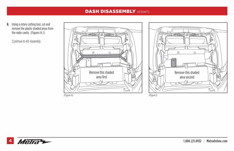
(Figure H) (Figure I)
8. Usingarotarycuttingtool,cutandremovetheplasticshadedareasfromtheradiocavity.(FiguresH,I)
Continue to Kit Assembly
Removethisshadedareafirst
Removethisshadedareasecond

REV. 4/30/2018 INST99-7809B 5
KIT ASSEMBLY
ISO DIN radio provision with pocket
1. Attachthe(8)PC-7871Bpanel clipstothe99-7809radio trim panel.
2. Attach(1)#8speedclipprovidedtoeachradio bracketasshown.(FigureA)
Note:This will be the lower mounting point where the factory 5/16” screws were removed.
3. Attachtheradio bracketstotheradio trim panelusing(4)#8x3/8”Phillipsscrewsprovided.(FigureB)
4. Mountthepockettothebracket/panelassemblywith(4)#8x3/8”Phillipsscrewsprovided.(FigureC)
5. Removethemetal“DIN”sleeveandtrimringfromtheaftermarketradio.
6. Slidetheradiointotheassemblyandsecurewithscrewssuppliedwiththeradio.(FigureC)
7. Clipthea/cventsremovedinstep#7ofthedisassemblyintotheradio trim panel.
(Figure A) (Figure C)
(Figure B) (Figure D)
8. Locatethefactorywiringharnessandantennapluginthedashandmakeallnecessaryconnectionstotheradio.MetrarecommendsusingthepropermatingadaptersfromMetraand/orAXXESS.
9. PluginandcliptheMetra climate control assemblyintothedash.(FigureD)
10. ProceedtotheWiringInstructionsectionofthismanualbeforemountingtheradioassemblyintothedashandcompletingthedashassembly.
11. AftertheMetraclimatecontrolsareprogrammedandtested,mountthenewradioassemblyintothedash,securethelowerradiobracketmountingpointswith(2)#10x3/4”Phillipsscrewsprovided,andreassemblethedashinreverseorderofdisassembly.
Continue to Wiring Instructions

1.800.221.0932 | MetraOnline.com6
KIT ASSEMBLY
ISO DDIN radio provision
1. Attachthe(8)PC-7871Bpanel clipstothe99-7809radio trim panel.
2. Attach(1)#8speedclipprovidedtoeachradiobracketasshown.(FigureA)
Note:This will be the lower mounting point where the factory 5/16” screws were removed.
3. Attachtheradio bracketstotheradio trim panelusing(4)#8x3/8”Phillipsscrewsprovided.(FigureB)
4. Slidetheradiointotheassemblyandsecurewithscrewssuppliedwiththeradio.(FigureC)
5. Clipthea/cventsremovedinstep#7ofthedisassemblyintotheradio trim panel.
(Figure C)
(Figure D)
6. Locatethefactorywiringharnessandantennapluginthedashandmakeallnecessaryconnectionstotheradio.MetrarecommendsusingthepropermatingadaptersfromMetraand/orAXXESS.
7. PluginandcliptheMetra climate control assemblyintothedash.(FigureD)
8. ProceedtotheKitProgrammingsectionofthismanualbeforemountingtheradioassemblyintothedashandcompletingthedashassembly.
9. AftertheMetraclimatecontrolsareprogrammedandtested,mountthenewradioassemblyintothedash,securethelowerradiobracketmountingpointswith(2)#10x3/4”Phillipsscrewsprovided,andreassemblethedashinreverseorderofdisassembly.
Continue to Wiring Instructions
(Figure A)
(Figure B)

REV. 4/30/2018 INST99-7809B 7
WIRING INSTRUCTIONS
From the 20-pin harness:
• ConnecttheRedwiretotheignitionwireoftheaftermarketradio.
• ConnecttheYellowwiretotheradio’s12-voltbatteryormemorywire.
• ConnecttheBlackwiretotheradio’sgroundwire.
• ConnecttheBluewiretotheantennaturnonwireoftheaftermarketradio.(ifapplicable)
• ConnecttheOrangewiretotheilluminationwireoftheaftermarketradio.IftheaftermarketradiohasnoilluminationwirejusttapeofftheOrange/Whitewire.
• ConnecttheWhitewiretotheleftfrontpositivespeakeroutput.
• ConnecttheWhite/Blackwiretotheleftfrontnegativespeakeroutput.
• ConnecttheGraywiretotherightfrontpositivespeakeroutput.
• ConnecttheGray/Blackwiretotherightfrontnegativespeakeroutput.
• ConnecttheGreenwiretotheradio’sleftrearpositivespeakeroutput.
• ConnecttheGreen/Blackwiretotheradio’sleftrearnegativespeakeroutput.
• ConnectthePurplewiretotheradio’srightrearpositivespeakeroutput.
• ConnectthePurple/Blackwiretotheradio’srightrearnegativespeakeroutput.
Additional 12-pin harness(ASWC harness)
This12-pinharnessistobeusedinconjunctionwiththeASWC-1(notincluded).
PleaserefertoASWCinstructionsforprogramming.TheASWC-1istoretainthefactorysteeringwheelcontrolsifequipped.
Plugthe6-pinconnectorintothe99-7809climatecontrolpanel.
Plugthe20-pinconnectortothevehiclesideharness.
Caution:
99-7809 applications only require the auto A/C plug locations. DO NOT use the manual plug location.
ThemicroBUSBconnectionisforfuturesoftwareupdatestothisifnecessary.Seeaxxessinterface.comforupdatinginformation.
Please disregard the white/red, white/ black, and black wires with bullet connectors coming from the 6-way plug. These are not used in any of the current 99-7809 applications.
Please disregard the plug location above the micro B USB connection. It will not be used.
Continue to Kit Programming on back cover
KNOWLEDGE IS POWEREnhance your installation and fabrication skills by enrolling in the most recognized and respected mobile electronics school in our industry.Log onto www.installerinstitute.com or call 800-354-6782 for more information and take steps toward a better tomorrow.
®
Metra recommends MECP certified technicians
IMPORTANTIf you are having difficulties with the installation of this product, please call our Tech Support line at 1-800-253-TECH. Before doing so, look over the instructions a second time, and make sure the installation was performed exactly as the instructions are stated. Please have the vehicle apart and ready to perform troubleshooting steps before calling.
The World’s best kits.® MetraOnline.com © COPYRIGHT 2018 METRA ELECTRONICS CORPORATION REV. 4/30/18 INST99-7809B
I N S TA L L AT I O N I N S T R U C T I O N S99-7809B
KIT PROGRAMMING
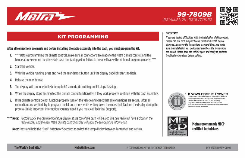
After all connections are made and before installing the radio assembly into the dash, you must program the kit.
1. ****Beforeprogrammingtheclimatecontrols,makesureallconnectionsaremadetotheMetraclimatecontrolsandthetemperaturesensoronthedriversidedashtrimispluggedin,failuretodosowillcausethekittonotprogramproperly.****
2. Startthevehicle.
3. Withthevehiclerunning,pressandholdthereardefrostbuttonuntilthedisplaybacklightstartstoflash.
4. Releasethereardefrost.
5. Thedisplaywillcontinuetoflashforupto60seconds,donothinguntilitstopsflashing.
6. Whenthedisplaystopsflashingtesttheclimatecontrolfunctionality.Iftheyworkproperly,continuewiththedashassembly.
7. Iftheclimatecontrolsdonotfunctionproperlyturnoffthevehicleandcheckthatallconnectionsaresecure.Afterallconnectionsareverified,trytoprogramthekitoncemorewhilewritingdownthecodesthatflashonthedisplayduringtheprocess(thisisimportantinformationyoumayneedifyoumustcallTechnicalSupport).
**** Note: Factory clock and cabin temperature display at the top of the dash will be lost. The new radio will have a clock on the radio display, and the new Metra climate control display will show the temperature information.
Note:Pressandholdthe“Dual”buttonfor5secondstoswitchthetempdisplaybetweenFahrenheitandCelsius.

¡PRECAUCIÓN! Todos los accesorios, interruptores, paneles de controles de clima y especialmente las luces del indicador de las bolsas de aire deben estar conectados antes ciclar la ignición. Además, no quite el radio de fábrica con la llave en la posición o de encendido ni con el vehículo funcionando.
The World’s best kits.® MetraOnline.com © COPYRIGHT 2018 METRA ELECTRONICS CORPORATION REV. 4/30/18 INST99-7809B
I N S T R U C C I O N E S D E I N S TA L AC I Ó N99-7809B
CARACTERÍSTICAS DEL KIT• ProvisiónderadioISODINconcavidad• ProvisiónderadioISODDIN• Pinturanegromate
COMPONENTES DEL KIT•A)Paneldemolduradelradio•B)Soportesdelradio•C)Ensambledecontroldeclima•D)Cavidad•E)(8)TornillosPhillips#8de3/8”•F)(2)TornillosPhillips#10de3/4”•G)(2)Ganchosdevelocidad#8•H)(8)GanchosparapanelPC-7871B•Arnésdecables(nosemuestra)
HERRAMIENTAS REQUERIDAS•Herramientaparaquitarpaneles•DestornilladorPhillips•Llavedetubode5/16”•Herramientadecortegiratorio
INDICE
Desmontajedeltablero.................................... 2-4Ensambledelkit–ProvisiónderadioISODINconcavidad............5–ProvisiónderadioISODDIN...............................6Instruccionesdeconexionesdecables................ 7Programacióndelkit.............................................8
CABLEADO Y CONEXIONES DE ANTENAArnésdecables:IncludioAdaptadordeantena:NorequeridoInterfasedecontrolenvolante:ASWC-1 (sevendeporseparado)
AcuraTSX2004-2008
A B C D E
F G H
1.800.221.0932 | MetraOnline.com2
DESMONTAJE DEL TABLERO
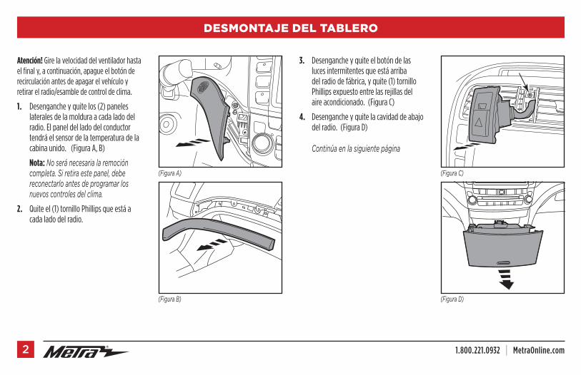
Atención! Girelavelocidaddelventiladorhastaelfinaly,acontinuación,apagueelbotónderecirculaciónantesdeapagarelvehículoyretirarelradio/esambledecontroldeclima.
1. Desengancheyquitelos(2)paneleslateralesdelamolduraacadaladodelradio.Elpaneldelladodelconductortendráelsensordelatemperaturadelacabinaunido.(FiguraA,B)
Nota:No será necesaria la remoción completa. Si retira este panel, debe reconectarlo antes de programar los nuevos controles del clima.
2. Quiteel(1)tornilloPhillipsqueestáacadaladodelradio.
3. Desengancheyquiteelbotóndelaslucesintermitentesqueestáarribadelradiodefábrica,yquite(1)tornilloPhillipsexpuestoentrelasrejillasdelaireacondicionado.(FiguraC)
4. Desengancheyquitelacavidaddeabajodelradio.(FiguraD)
Continúa en la siguiente página
(Figura A) (Figura C)
(Figura B) (Figura D)
REV. 4/30/2018 INST99-7809B 3
DESMONTAJE DEL TABLERO (CONT)
(Figura E) (Figura G)(Figura F)
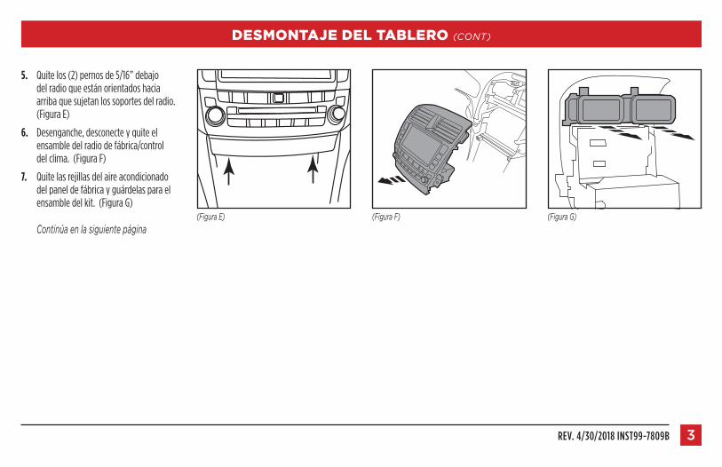
5. Quitelos(2)pernosde5/16”debajodelradioqueestánorientadoshaciaarribaquesujetanlossoportesdelradio.(FiguraE)
6. Desenganche,desconecteyquiteelensambledelradiodefábrica/controldelclima.(FiguraF)
7. Quitelasrejillasdelaireacondicionadodelpaneldefábricayguárdelasparaelensambledelkit.(FiguraG)
Continúa en la siguiente página

1.800.221.0932 | MetraOnline.com4
DESMONTAJE DEL TABLERO (CONT)
(Figura H) (Figura I)
8. Usandouncortadorgiratorio,corteyquitelasáreassombreadasdelacavidaddelradio.(FigurasH,I)
Continúe con el Ensamble del Kit
Quiteprimeroeláreasombreada
Quiteestaáreasombreadadespués
REV. 4/30/2018 INST99-7809B 5
ENSAMBLE DEL KIT
Provisión de radio ISO DIN con cavidad
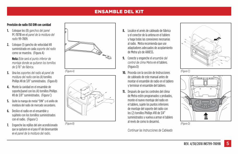
1. Coloquelos(8)ganchos del panelPC-7871Benelpanel de la moldura del radio99-7809.
2. Coloque(1)ganchodevelocidad#8suministradoencadasoporte del radiocomosemuestra.(FiguraA)
Nota:Este será el punto inferior de montaje donde se quitaron los tornillos de 5/16” de fábrica.
3. Unalossoportes del radioalpanel de moldura del radioconlos(4)tornillosPhillips#8de3/8”suministrados.(FiguraB)
4. Montelacavidadenelensambledesoporte/panelconlos(4)tornillosPhillips#8de3/8”suministrados.(FiguraC)
5. Quitelamangademetal“DIN”yelanillodemolduradelradiodemercadosecundario.
6. Desliceelradioenelensambleysujételoconlostornillossuministradosconelradio.(FiguraC)
7. Enganchelasrejillasdelaireacondicionadoquesequitaronenelpaso#7deldesensambleenelpanel de la moldura del radio.
(Figura A) (Figura C)
(Figura B) (Figura D)
8. Localiceelarnésdecableadodefábricayelconectordelaantenaeneltableroyhagatodaslasconexionesnecesariasalradio.MetrarecomiendaqueuseadaptadoresadecuadosdeacoplamientodeMetray/odeAXXESS.
9. Conecteyengancheelensamble del control de clima Metraeneltablero.(FiguraD)
10. ProcedaconlaseccióndeInstruccionesdecableadodeestemanualantesdemontarelensamblederadioeneltableroyterminarelensambledeltablero.
11. DespuésdequeloscontrolesdelclimadeMetraesténprogramadosyprobados,monteelnuevomontajedelradioeneltablero,sujetelospuntosinferioresdemontajedelsoportedelradioconlos(2)tornillosPhillips#10de3/4”suministradosyvuelvaaarmareltableroalrevésdecomolodesarmó.
Continuar las Instrucciones de Cableado

1.800.221.0932 | MetraOnline.com6
ENSAMBLE DEL KIT
Provisión de radio ISO DDIN
1. Coloquelos(8)ganchosdelpanelPC-7871Benelpanel de la moldura del radio99-7809.
2. Coloque(1)ganchodevelocidad#8suministradoencadasoportedelradiocomosemuestra.(FiguraA)
Nota:Este será el punto inferior de montaje donde se quitaron los tornillos de 5/16” de fábrica.
3. Unalossoportes del radioalpanel de moldura del radioconlos(4)tornillosPhillips#8de3/8”suministrados.(FiguraB)
4. Desliceelradioenelensambleysujételoconlostornillossuministradosconelradio.(FiguraC)
5. Enganchelasrejillasdelaireacondicionadoquesequitaronenelpaso#7deldesensambleenelpanel de la moldura del radio.
(Figura C)
(Figura D)
6. Localiceelarnésdecableadodefábricayelconectordelaantenaeneltableroyhagatodaslasconexionesnecesariasalradio.MetrarecomiendaqueuseadaptadoresadecuadosdeacoplamientodeMetray/odeAXXESS.
7. Conecteyengancheelensamble del control de clima Metraeneltablero.(FiguraD)
8. ProcedaconlaseccióndeInstruccionesdecableadodeestemanualantesdemontarelensamblederadioeneltableroyterminarelensambledeltablero.
9. DespuésdequeloscontrolesdelclimadeMetraesténprogramadosyprobados,monteelnuevomontajedelradioeneltablero,sujetelospuntosinferioresdemontajedelsoportedelradioconlos(2)tornillosPhillips#10de3/4”suministradosyvuelvaaarmareltableroalrevésdecomolodesarmó.
Continuar las Instrucciones de Cableado
(Figura A)
(Figura B)

REV. 4/30/2018 INST99-7809B 7
INSTRUCCIONES DE CONEXIONES DE CABLES
Desde el arnés de 20 pins:
• Conecteelcablerojoconelcabledeignicióndelradiodemercadosecundario.
• Conecteelcableamarilloalabateríade12voltiosoelcabledememoriadelradio.
• Conecteelcablenegroconelcabledepuestaatierradelradio.
• Conecteelcableazulconelcabledeencendidodelaantenadelradiodemercadosecundario.(siprocede)
• Conecteelcableanaranjadoconelcabledeiluminacióndelradiodemercadosecundario.Sielradiodemercadosecundarionotienecabledeiluminaciónsolocubraconcintaelalambreanaranjado/blanco.
• Conecteelcableblancoconlasalidapositivadelabocinaizquierdadelantera.
• Conecteelcableblanco/negroconlasalidanegativadelabocinaizquierdadelantera.
• Conecteelcablegrisconlasalidapositivadelabocinaderechadelfrente.
• Conecteelcablegris/negroconlasalidanegativadelabocinaderechadelfrente.
• Conecteelcableverdeconlasalidapositivadelabocinaizquierdadeatrásdelradio.
• Conecteelcableverde/negroconlasalidanegativadelabocinaizquierdadeatrásdelradio.
• Conecteelcablepúrpuraconlasalidapositivadelabocinaderechadeatrásdelradio.
• Conecteelcablepúrpura/negroconlasalidanegativadelabocinaderechadeatrásdelradio.
Arnés de 12 pins adicional (Arnés ASWC)
Estearnésde12pinssedebeusarjuntoconelASWC-1(noincluido).
ConsultelasinstruccionesdeASWCparalaprogramación.ElASWC-1espararetenerloscontrolesenelvolantedefábricasicuentacondichoequipamiento.
Conecteelconectorde6pinsalpaneldelcontroldeclima99-7809.
Conecteelconectorde20pinsalarnéslateraldelvehículo.
Precaución:
Las aplicaciones de 99-7809 solo requieren las ubicaciones de conexión automática del aire acondicionado. NO use la ubicación de conexión manual.
LaconexiónmicroBUSBesparafuturasactualizacionesdesoftwareencasodequeestoseanecesario.Veaenaxxessinterface.comlainformaciónactualizada.
Por favor ignore los cables blanco/rojo, blanco/negro y negro con conectores tipo bala que vienen del conector de 6 vías. No se utilizan en ninguna de las aplicaciones actuales del 99-7809.
Por favor ignore la ubicación de conexión arriba de la conexión micro B USB. No se utilizará.
Continúe con la Programación del Kit en el reverso

KNOWLEDGE IS POWEREnhance your installation and fabrication skills by enrolling in the most recognized and respected mobile electronics school in our industry.Log onto www.installerinstitute.com or call 800-354-6782 for more information and take steps toward a better tomorrow.
®
Metra recomienda técnicos con certificación del Programa de Certificación en Electrónica Móvil (Mobile Electronics Certification Program, MECP).
EL CONOCIMIENTO ES PODERMejore sus habilidades de instalación y fabricación inscribiéndose en la escuela de dispositivos electrónicos móviles más reconocida y respetada de nuestra industria. Regístrese en www.installerinstitute.com o llame al 800-354-6782 para obtener más información y avance hacia un futuro mejor.
The World’s best kits.® MetraOnline.com © COPYRIGHT 2018 METRA ELECTRONICS CORPORATION REV. 4/30/18 INST99-7809B
I N S T R U C C I O N E S D E I N S TA L AC I Ó N99-7809B
IMPORTANTESi tiene dificultades con la instalación de este producto, llame a nuestra línea de soporte técnico al 1-800-253-TECH. Antes de hacerlo, revise las instrucciones por segunda vez y asegúrese de que la instalación se haya realizado exactamente como se indica en las instrucciones. Por favor tenga el vehículo desarmado y listo para ejecutar los pasos de resolución de problemas antes de llamar.
PROGRAMACIÓN DEL KIT
Después de que todas las conexiones estén hechas y antes de instalar el ensamble del radio en el tablero, debe programar el kit.
1. ****Antesdeprogramarloscontrolesdelclima,asegúresedequetodaslasconexionesesténhechasaloscontrolesdelclimadeMetrayqueelsensordetemperaturadelamolduradeltablerodelladodelconductorestéconectado,nohacerloocasionaráqueelkitnoseprogrameadecuadamente.****
2. Enciendaelvehículo.
3. Conelvehículoencendido,presioneymantengapresionadoelbotóndedesempañadotraserohastaquelaretroiluminacióndelapantallaempieceaparpadear.
4. Suelteelbotóndedesempañadotrasero.
5. Lapantallacontinuaráparpadeandohasta60segundos,nohaganadahastaquedejedeparpadear.
6. Cuandolapantalladejedeparpadearpruebelafuncionalidaddelcontroldeclima.Sifuncionanadecuadamente,continúeconelensambledeltablero.
7. Siloscontrolesdelclimanofuncionanadecuadamente,apagueelvehículoyverifiquequetodaslasconexionesesténbiensujetas.Despuésdequetodaslasconexionesesténverificadas,tratedeprogramarelkitunavezmásmientrasescribeloscódigosqueparpadeanenlapantalladuranteelproceso(estaesinformaciónimportantequepuedenecesitarsillamaasoportetécnico).
**** Nota: Se perderán reloj fábrica y visualización de la temperatura de la cabina en la parte superior del tablero. La nueva radio tendrá un reloj en la pantalla de la radio, y la nueva pantalla de control climático Metra mostrará la información de la temperatura.
Nota: Mantengapresionadoelbotón“Dual”durante5segundosparacambiarlavisualizacióndetemperaturaentreFahrenheityCelsius.