inspection and testing pocket notes - sparkyfacts and te… · · 2018-01-15criteria regarding...
TRANSCRIPT

SparkyFacts | Guides, Tips & Tricks for Electrical Courses, Qualifications and Exams Copyright © SparkyFacts.co.uk
Inspection and Testing Pocket Notes
Type of test Initial Verification Periodic Inspection
Purpose of test
1. All equipment is correct type and complies with relevant British Standard
2. All parts of Installation are correctly selected and erected
3. No part of installation visibly damaged or otherwise defective
1. Safety of persons and livestock against of electric shock
2. Protection against damage to property by fire or heat from installation defect
3. Installation is not damaged or deteriorated so as to impair safety
4. Identify installation defects and non compliance with regs which may give rise to danger
Information required by inspector
1. Maximum demand 2. Number and type of live conductors 3. Earthing arrangements 4. Nominal voltage 5. Nature of current and frequency 6. Prospective fault current 7. External earth fault loop impedance 8. Suitability for the requirements of
insulation 9. Type/rating of incoming protective
device
Diagrams, charts and tables should be available and contain: 1. Type, composition, utilisation, size
of conductor and type of cable for each circuit
2. Methods of basic and fault protection
3. Identification of devices for protection, isolation and switching
4. Details of equipment vulnerable to test
1. Extent of installation to be inspected 2. Criteria regarding limitation of inspection 3. Enquires to be made with regard to
provision or diagrams, supply and earthing arrangements
4. Diagrams to indicate composition of circuits identification of protective devices, isolation and switching and methods of basic and fault protection
If the information available is limited it may be necessary to carry out certain
SparkyFacts | Guides, Tips & Tricks for Electrical Courses, Qualifications and Exams Copyright © SparkyFacts.co.uk
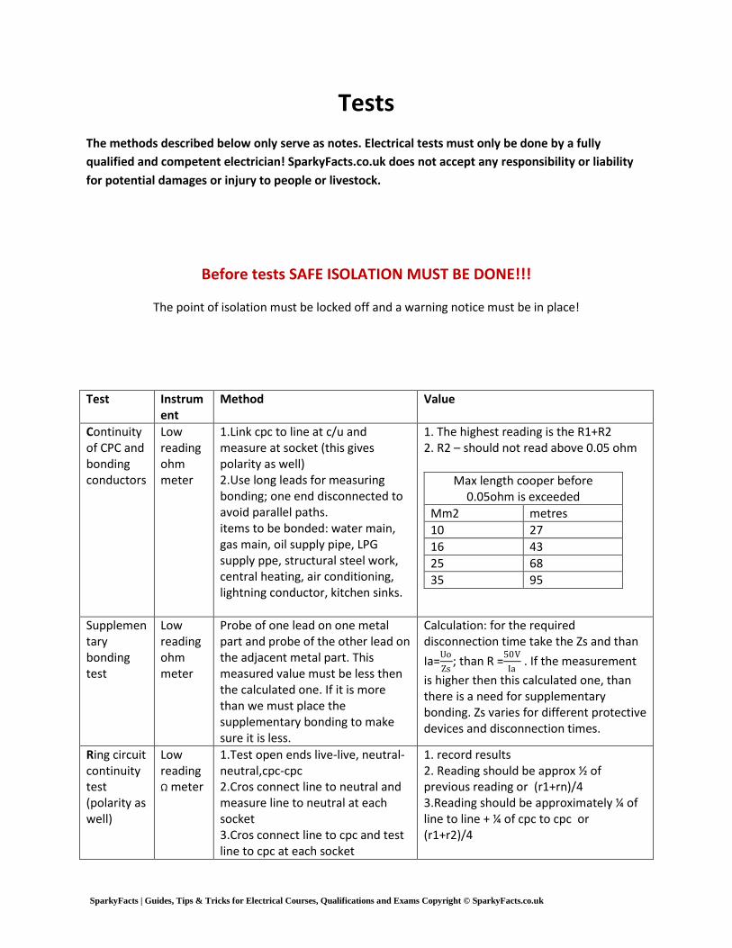
Tests
The methods described below only serve as notes. Electrical tests must only be done by a fully
qualified and competent electrician! SparkyFacts.co.uk does not accept any responsibility or liability
for potential damages or injury to people or livestock.
Before tests SAFE ISOLATION MUST BE DONE!!!
The point of isolation must be locked off and a warning notice must be in place!
Test Instrument
Method Value
Continuity of CPC and bonding conductors
Low reading ohm meter
1.Link cpc to line at c/u and measure at socket (this gives polarity as well) 2.Use long leads for measuring bonding; one end disconnected to avoid parallel paths. items to be bonded: water main, gas main, oil supply pipe, LPG supply ppe, structural steel work, central heating, air conditioning, lightning conductor, kitchen sinks.
1. The highest reading is the R1+R2 2. R2 – should not read above 0.05 ohm
Max length cooper before 0.05ohm is exceeded
Mm2 metres
10 27
16 43
25 68
35 95
Supplementary bonding test
Low reading ohm meter
Probe of one lead on one metal part and probe of the other lead on the adjacent metal part. This measured value must be less then the calculated one. If it is more than we must place the supplementary bonding to make sure it is less.
Calculation: for the required disconnection time take the Zs and than
Ia=Uo
Zs; than R =
50V
Ia . If the measurement
is higher then this calculated one, than there is a need for supplementary bonding. Zs varies for different protective devices and disconnection times.
Ring circuit continuity test (polarity as well)
Low reading Ω meter
1.Test open ends live-live, neutral-neutral,cpc-cpc 2.Cros connect line to neutral and measure line to neutral at each socket 3.Cros connect line to cpc and test line to cpc at each socket
1. record results 2. Reading should be approx ½ of previous reading or (r1+rn)/4 3.Reading should be approximately ¼ of line to line + ¼ of cpc to cpc or (r1+r2)/4

SparkyFacts | Guides, Tips & Tricks for Electrical Courses, Qualifications and Exams Copyright © SparkyFacts.co.uk
Insulation resistance test
Insulation resistance tester – high reading Ω meter
Isolate circuit! Lamps and equipment removed!! Main switch, MCB`s and all switches on. Test at the DB on the incoming side of the main switch. Test L-CPC , N-CPC, L-N, or where equipment is vulnerable test between LN together and CPC. For 3 phase test between all L conductors, then between all L and N, then between all L and CPC, then between N and CPC.
SELV and PELV 250V min 0.5 Mohm ; LV 500V min 1 Mohm Values lower then 2Mohm needs further investigation ; circuits must be tested separately.
Polarity dead
Low reading Ω meter
1.Link line and cpc at c/u 2. Neutral with long leed
1. R1+R2 2. Rn
Polarity live
Volt meter
Live test! At the incoming side of the main switch. 1.Line to neutral 2.Line to earth 3.Neutral to earth
1. 230V 2. 230V 3. 0V
Loop tests – Ze, Zs and earth electrode
Earth Loop Impedance tester – low reading in Ω
WARNING – NEVER test between Line and Line (400V)!!!!!! Ze – LIVE TEST!!! Supply on, but the installation isolated! The earthing conductor disconnected. Test at the incoming (live) side of the main switch and the supply earth. Green lead to incoming earth. Test between N and L. For 3phase test between N-L1 , N-L2 , N-L3. The highest reading is the Ze. Zs – The whole installation energised!! Measure at all sockets and outlets with eider using three leads or socket plug. The highest value is the Zs. For 3 phase measure with green on earth, black on neutral and red on L1, than red on L2 then red on L3. The highest is Zs. If Zs test trips the RCD than we can use the “no trip” function of the tester if we have one, or we can calculate the Zs. Earth electrode test – 1. With proprietary tester and two other electrodes. All three electrodes connected to the tester.
Ze – low reading ohm Zs – low reading ohm
Earth electrode- max 200 ohm in practice
max measured Zs for Type B MCB`s (by rule of thumb)
3 A 6 A 10 A 16 A 20 A 25 A 32 A
11.6 Ω
5.82 Ω
3.49 Ω
2.18 Ω
1.74 Ω
1.39 Ω
1.08 Ω

SparkyFacts | Guides, Tips & Tricks for Electrical Courses, Qualifications and Exams Copyright © SparkyFacts.co.uk
2.With earth loop impedance tester the same way as Ze.
Earth fault current and short circuit current
Prospective fault current tester
We measure these values at the same turn every time when measure Ze. Live test!!! Supply on, but the installation isolated! Test on the incoming side of the main switch. Earth fault current – green lead to earth. Test between N-L. For 3phase test between N-L1 , N-L2 , N-L3. The highest value is the earth fault current. Short circuit current – Green on neutral as well. Test between N-L. For 3phase test between N-L1 , N-L2 , N-L3. The highest value is the short circuit current. PFC to enter on documentations – whichever is the higher of the two determined test values on single phase. For 3phase double the highest measured Line to Neutral value to get the PFC.
High value in Amps. The protective device must be able to clear this value For single phase the higher value of the two tests should be recorded on the test certificate. For 3 phase take the highest value between Line and Neutral and double it, this should be recorded. On TNCS systems we can calculate by:
PSCC=230v
Ze= A
Examples PSCC
Semi-enclosed BS 3036
1kA to 4kA depending on type
BS1361 Type 1 16.5 kA
BS 1361 Type 2 33 kA
BS 88-2.1 50 kA at 415V
BS 88-6 16.5 kA at 240V 80 kA at 415V
RCD and other functional tests
RCD tester
LIVE test!!! Test with 50%, 100% and when RCD is a supplementary protection then 500% as well. Test by plugging in the tester to a RCD protected socket and test both side of an AC wave for max 2 sec. After the tests manually test by pushing the test button on the RCD.
Max trip time
Test current
BS 4293 BSEN 61008
BSEN 61009
50% In No trip No trip No trip
100% In 200ms 300ms 300ms
500% In 40ms 40ms 40ms
After these tests all switches, isolators, thermostats and circuit breakers should be checked to work
properly.
SparkyFacts | Guides, Tips & Tricks for Electrical Courses, Qualifications and Exams Copyright © SparkyFacts.co.uk
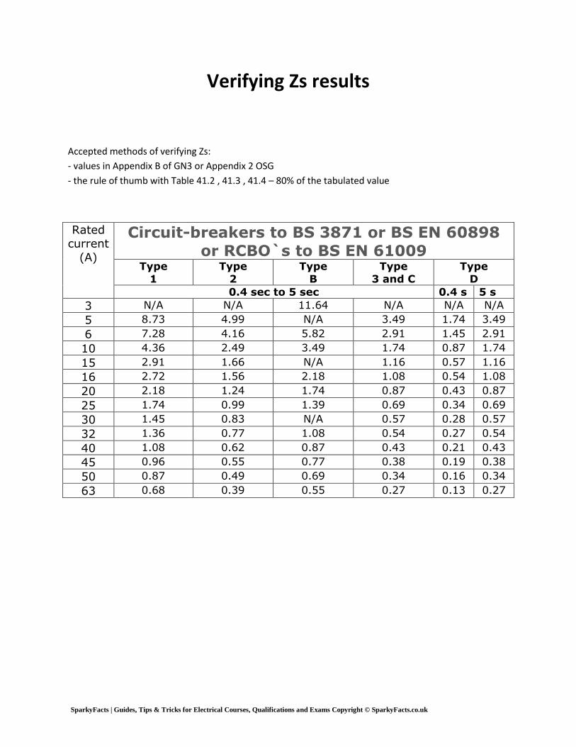
Verifying Zs results
Accepted methods of verifying Zs:
- values in Appendix B of GN3 or Appendix 2 OSG
- the rule of thumb with Table 41.2 , 41.3 , 41.4 – 80% of the tabulated value
Rated current
(A)
Circuit-breakers to BS 3871 or BS EN 60898
or RCBO`s to BS EN 61009 Type
1
Type
2
Type
B
Type
3 and C
Type
D
0.4 sec to 5 sec 0.4 s 5 s
3 N/A N/A 11.64 N/A N/A N/A
5 8.73 4.99 N/A 3.49 1.74 3.49
6 7.28 4.16 5.82 2.91 1.45 2.91
10 4.36 2.49 3.49 1.74 0.87 1.74
15 2.91 1.66 N/A 1.16 0.57 1.16
16 2.72 1.56 2.18 1.08 0.54 1.08
20 2.18 1.24 1.74 0.87 0.43 0.87
25 1.74 0.99 1.39 0.69 0.34 0.69
30 1.45 0.83 N/A 0.57 0.28 0.57
32 1.36 0.77 1.08 0.54 0.27 0.54
40 1.08 0.62 0.87 0.43 0.21 0.43
45 0.96 0.55 0.77 0.38 0.19 0.38
50 0.87 0.49 0.69 0.34 0.16 0.34
63 0.68 0.39 0.55 0.27 0.13 0.27

SparkyFacts | Guides, Tips & Tricks for Electrical Courses, Qualifications and Exams Copyright © SparkyFacts.co.uk
Voltage drop
It is part of the inspection process.
1. Method – measure the voltage at the origin of the circuit, and then measure the voltage at the end of
the circuit with load connected and switched on.
2. Method – Insulation resistance test between the phase and neutral. The measured resistance should
be multiplied by the current that will flow in the circuit. This gives the voltage drop.
Determining if a part is extraneous or just a piece
of metal
A test should be made using an insulation resistance tester set on Mohm supplying 500V. Connect one
test lead to the metal part and the other lead to a known earth. If the measured value is >0.02 Mohm
than there is no need for supplementary bonding if less than supplementary bonding should be carried
out.
SparkyFacts | Guides, Tips & Tricks for Electrical Courses, Qualifications and Exams Copyright © SparkyFacts.co.uk
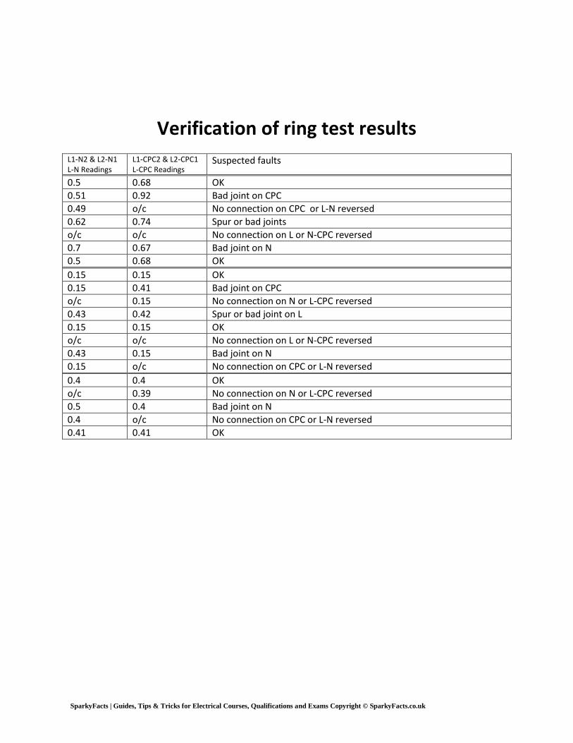
Verification of ring test results
L1-N2 & L2-N1 L-N Readings
L1-CPC2 & L2-CPC1 L-CPC Readings
Suspected faults
0.5 0.68 OK
0.51 0.92 Bad joint on CPC
0.49 o/c No connection on CPC or L-N reversed
0.62 0.74 Spur or bad joints
o/c o/c No connection on L or N-CPC reversed
0.7 0.67 Bad joint on N
0.5 0.68 OK
0.15 0.15 OK
0.15 0.41 Bad joint on CPC
o/c 0.15 No connection on N or L-CPC reversed
0.43 0.42 Spur or bad joint on L
0.15 0.15 OK
o/c o/c No connection on L or N-CPC reversed
0.43 0.15 Bad joint on N
0.15 o/c No connection on CPC or L-N reversed
0.4 0.4 OK
o/c 0.39 No connection on N or L-CPC reversed
0.5 0.4 Bad joint on N
0.4 o/c No connection on CPC or L-N reversed
0.41 0.41 OK
SparkyFacts | Guides, Tips & Tricks for Electrical Courses, Qualifications and Exams Copyright © SparkyFacts.co.uk
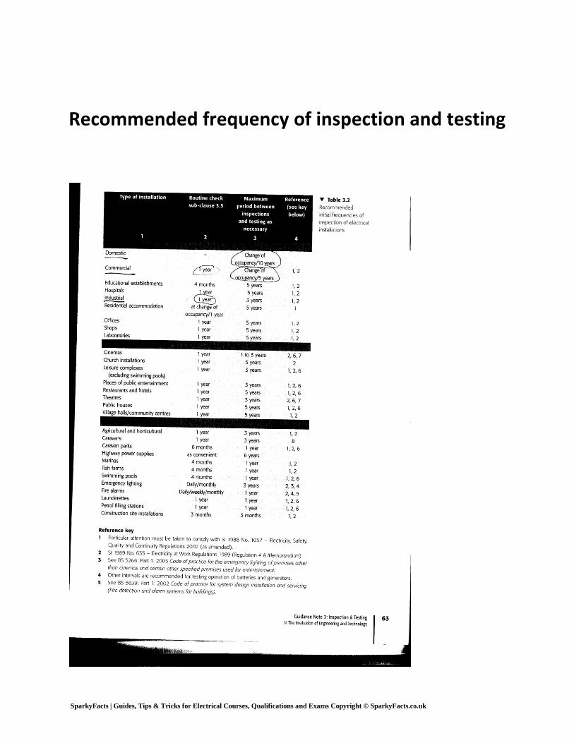
Recommended frequency of inspection and testing