input and design features
TRANSCRIPT

www.sgh.com
DES
IGN
INV
ESTIG
ATE
REHA
BILI
TATE
Introduction to the Capabilities of CANDE-2007
Input and Design Features
Tim McGrath
CANDE 2007 – Design By AASHTO
• ASD (Called service in the Tutorial)– analysis for service loads– computes factors of safety for comparison with target values
• LRFD– AASHTO LRRFD Bridge Design Specifications, 4th Ed– Input load and resistance factors – Analysis for factored loads– Compares factored load to factored capacity
5 August 2009 CANDE 2007 Capabilities 2
AAHSTO LRFD
• Load Modifiers – Section 1– ductility, redundance, importance– culverts – live load redundant, earth load is not
• Load Factors – Section 3 – Earth, live, water
• Resistance Factors – Section 12– Vary by material and limit state
5 August 2009 CANDE 2007 Capabilities 3

Corrugated Metal Design Criteria
5 August 2009 CANDE 2007 Capabilities 4
Design Criterion (Strength limits)
Demand Capacity
Thrust stress (psi) max maxσ = N /A yf = yield strength Global Buckling (psi) max maxσ = N /A bf = buckling capacity Seam strength (psi) max maxσ = N /A sf = seamstrength Plastic Penetration % pp = computed % plastic
failure = 100%
(Performance Limits) Allowable deflection %
maxΔ = computed deflect %
Allowable = 5% (Long Spans = 2%)

Concrete Design Criteria
5 August 2009 CANDE 2007 Capabilities 5
Design Criterion (Strength limits)
Demand Capacity
Steel yielding (psi) maxf = max steel stress yf = yield strength
Concrete crushing (psi) maxσ = max compression cf = compressivestrength′
Shear failure (lb/in) maxV = max shear force ultV = concrete shear capacity
Radial tension failure (psi) maxt = max radial stress ultt = ultimate radial strength
(Performance Limits)
Allowable crack (in) maxCW = max crack width ( )AllowCW = allowable CW 0.01inch

Thermoplastic Design Criteria
5 August 2009 CANDE 2007 Capabilities 6
Design Criterion (Strength limits)
Demand Capacity
Thrust stress (psi) max maxσ = N /A uf = ultimatestrength Global Buckling (psi) max maxσ = N /A bf = buckling capacity Combined strain (in/in) maxε = bending + thrust ultε = ultimatestrain (Performance Limits)
Allowable tensile strain -maxtε = max tensilestrain
t-allowε = allowable tensilestrain
Allowable deflection % maxΔ = computed deflect %
Allowable = 5% (recommended)

16 Tutorial Problems
5 August 2009 CANDE 2007 Capabilities 7
ExampleNo.
SolutionLevel
MaterialType
StructureType
InstallationType
ExecutionMode
Method of Analysis/ Design
…
7 2 R/C Box Embankment Analysis LRFD
8 2 Steel Pipe Embankment Analysis LRFD
9 2 Steel Arch Trench Analysis Service
10 2 R/C Pipe Embankment Design LRFD
11 2 Plastic Pipe Trench Analysis Service
12 3 R/C Box Embankment Analysis LRFD…

16 Tutorial Problems
5 August 2009 CANDE 2007 Capabilities 8
ExampleNo. Design Features CANDE Interface Features
…7 N/A N/A
8Uses slotted joints and Level 2 extended to add smaller construction steps above the crown of the pipe
N/A
9Uses interface elements, Level 2 extended to apply live load, and large deformation / buckling analysis
Shows inputting interface angles using the graphic interface.
10 Includes soft backpacking soil around Pipe
Shows how to modify chart properties of graphs plotted using 'view/graphs.'
11
Profile analysis, includes interface elements, Level 2 extended to add soft haunches, long-term load duration, and global and local buckling calculations
Shows how to modify the input file using the text input including inputting a user defined soil material and how to compute interface angles for a pipe
12 Identical to Problem 7, except Level 3 Shows a user generated Level 3 mesh
…

16 Tutorial Problems
5 August 2009 CANDE 2007 Capabilities 9
ExampleNo. Design Features CANDE Interface Features
…7 N/A N/A
8Uses slotted joints and Level 2 extended to add smaller construction steps above the crown of the pipe
N/A
9Uses interface elements, Level 2 extended to apply live load, and large deformation / buckling analysis
Shows inputting interface angles using the graphic interface.
10 Includes soft backpacking soil around Pipe
Shows how to modify chart properties of graphs plotted using 'view/graphs.'
11
Profile analysis, includes interface elements, Level 2 extended to add soft haunches, long-term load duration, and global and local buckling calculations
Shows how to modify the input file using the text input including inputting a user defined soil material and how to compute interface angles for a pipe
12 Identical to Problem 7, except Level 3 Shows a user generated Level 3 mesh
…
Uses interface elements, Level 2 extended to apply live load, and large deformation / buckling analysis

16 Tutorial Problems
5 August 2009 CANDE 2007 Capabilities 10
ExampleNo. Design Features CANDE Interface Features
…7 N/A N/A
8Uses slotted joints and Level 2 extended to add smaller construction steps above the crown of the pipe
N/A
9Uses interface elements, Level 2 extended to apply live load, and large deformation / buckling analysis
Shows inputting interface angles using the graphic interface.
10 Includes soft backpacking soil around Pipe
Shows how to modify chart properties of graphs plotted using 'view/graphs.'
11
Profile analysis, includes interface elements, Level 2 extended to add soft haunches, long-term load duration, and global and local buckling calculations
Shows how to modify the input file using the text input including inputting a user defined soil material and how to compute interface angles for a pipe
12 Identical to Problem 7, except Level 3 Shows a user generated Level 3 mesh
…
Shows inputting interface angles using the graphic interface.

Problem 1 (P1) – Level 1, 60 in. CSP, Design
5 August 2009 CANDE 2007 Capabilities 11

P1 – Selected Input Parameters
5 August 2009 CANDE 2007 Capabilities 12
Method of analysis/design - Design - LRFD
Interface - Fully bonded (Slip is the other option)
Joint slip - No joint slip
Material behavior - Linear stress/strain
Analysis mode - Small deformation
Average diameter of pipe - Centroid of pipe wall = 61 in.
Number of load steps - Apply load in 10 equal load steps of 3 ft of soil.
LRFD load factor - 1.95
Load modifier - 1.05 (non-redundant for earth load)
Combined load factor = 1.95 x 1.05 = 2.05

P1 - Level 1 – Input Wizard, Screen 1
5 August 2009 CANDE 2007 Capabilities 13

P1 - Level 1 – Input Wizard, Screen 2
5 August 2009 CANDE 2007 Capabilities 14

P1 - Master Control Screen
5 August 2009 CANDE 2007 Capabilities 15
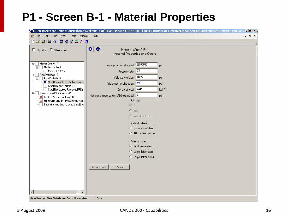
P1 - Screen B-1 - Material Properties
5 August 2009 CANDE 2007 Capabilities 16

P1 - Screen B-2 - Design Weights
5 August 2009 CANDE 2007 Capabilities 17

P1 - Screen B-3 - Resistance Factors
5 August 2009 CANDE 2007 Capabilities 18

P1 - Screen C-1 - Major Input Parameters
5 August 2009 CANDE 2007 Capabilities 19

P1 - Screen C-2 - Fill Height, Soil Parameters
5 August 2009 CANDE 2007 Capabilities 20

P1 - Screen C-3 – LRFD Load Factors
5 August 2009 CANDE 2007 Capabilities 21
Note: Load factor includes load modifier

P1 – Design Solution
5 August 2009 CANDE 2007 Capabilities 22

Problem 6 (P6) – Concrete Arch, Level 2
5 August 2009 CANDE 2007 Capabilities 23

P6 – Input Wizard - Screen 1
5 August 2009 CANDE 2007 Capabilities 24
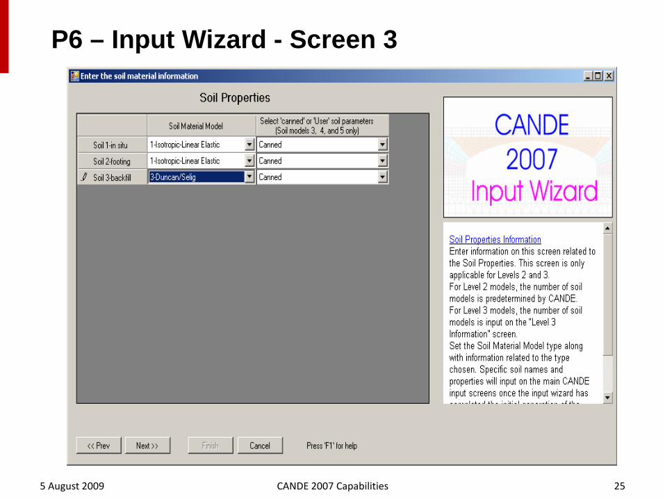
P6 – Input Wizard - Screen 3
5 August 2009 CANDE 2007 Capabilities 25

P6 - Master Control A-1
5 August 2009 CANDE 2007 Capabilities 26

P6 – Screen B-3 - Reinforcement
5 August 2009 CANDE 2007 Capabilities 27
CANDE 2007 Does not include the current crack control equation for box sections. The Heger McGrath method is more conservative and generally does not control design.

P6 – Screen CX-4 – Boundary Conditions (LL)
5 August 2009 CANDE 2007 Capabilities 28

P6 – Screen D-1 – Soil Definition
5 August 2009 CANDE 2007 Capabilities 29

P6 – Mesh, Soil Zones, and Load Increments
5 August 2009 CANDE 2007 Capabilities 30
Live load boundary conditions

P6 – Output Design Assesment
5 August 2009 CANDE 2007 Capabilities 31
5 August 2009 CANDE 2007 Capabilities 32
Up Next –
Tim Toliver

(Culvert ANalysis and DEsign)
TRB WebinarCANDE Overview
August 5, 2009
Presented byMike Katona
CANDE 2007

CANDE BACKGROUND
• CANDE Purpose
• CANDE History
• CANDE Users

- CANDE PURPOSE -
CANDE is a plane-strain structural analysis and design computer program for buried structures incorporating soil and structure.
Plastics Reinforced Concrete
CorrugatedMetal
SoilLayers
Live Loads
X
Y
Z

- CANDE HISTORY -
DATE COMMENTS SPONSOR
1976 • First release to culvert community• Mainframe computer required
FHWA
1980 • Incorporate Duncan Soil model• Improve r/concrete model• Add slotted joints for corrugated steel
FHWA
1989 • Develop PC version • Add Level 2 Arch• Improve Duncan/Selig soil model
FHWA
2007 • Graphical user interface for input/output• Large deformation and buckling prediction• Multiple pipe type capability (groups)• LRFD design criteria and methodology• Bandwidth minimizer
AASHTO• NCHRP 15-28• Report 619

-- CANDE-2007 DEVELOPERS -
Principal Investigators for CANDE-2007 (NCHRP 15-28)
• Mark Mlynarski (Michael Baker Jr, Inc.)Responsible for graphical user interface input/output and oversight.
• Tim McGrath (SGH)Responsible for LRFD interpretations and tutorial manual.
• Mike KatonaResponsible for CANDE Engine, new capabilities and models.

- CANDE USERS –
1. DOT Engineers and Consultants* Evaluate alternative new culvert designs
* Check safety of existing culverts and rehabilitation methods
2. Culvert Manufacturers and Suppliers* Develop new culvert products and installation methods
* Design specific solutions for customers
3. Researchers and Investigators* Interpret experimental data from field and laboratory
* Test bed for new theoretical soil and pipe models

CANDE CAPABILITY OVERVIEW - 1
Major Input Selections (user choices)• Execution Mode – Analysis or Design
• Evaluation Method – Working stress or LRFD
• Pipe Type(s) – CMP, R/C and Plastic
• Solution Level – Level 1, 2 or 3
• System Choices – Soil models, interfaces, loading, etc.

- EXECUTION MODE: DESIGN or ANALYSIS -Pipe Type Design Criteria Analysis Design Goal
Corrugated Metal • Thrust yielding• Buckling• Seam failure• Plastic hinging• Deflection limit
Evaluatesafety
Specify safety.Find corrugation size and gage
Reinforced Concrete • Steel yielding• Concrete crush• Shear failure• Radial tension• Crack width
Evaluatesafety
Specify safety.Find steel areas.
Plastic • Thrust yielding• Buckling• Combined strain• Tensile strain• Deflection
Evaluatesafety
Specify safety.Find thickness.

CANDE CAPABILITY OVERVIEW - 2
Major Input Selections (user choices)• Execution Mode – Analysis or Design
• Evaluation Method – Working stress or LRFD
• Pipe Type(s) – CMP, R/C and Plastic
• Solution Level – Level 1, 2 or 3
• System Choices – Soil models, interfaces, loading, etc.
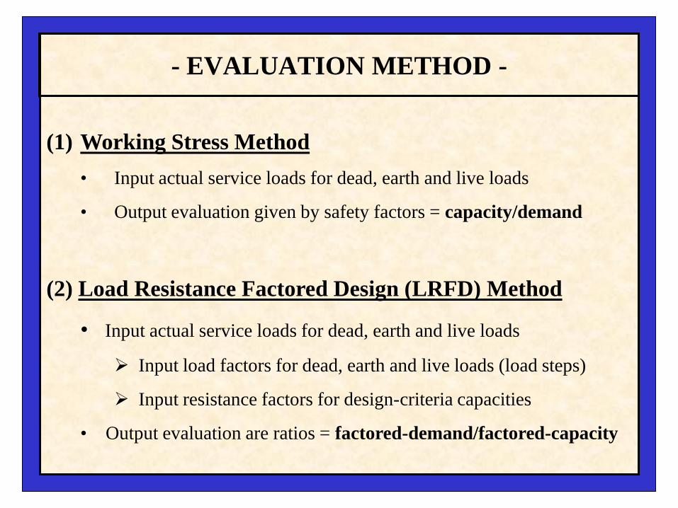
- EVALUATION METHOD -
(1) Working Stress Method• Input actual service loads for dead, earth and live loads
• Output evaluation given by safety factors = capacity/demand
(2) Load Resistance Factored Design (LRFD) Method
• Input actual service loads for dead, earth and live loads
Input load factors for dead, earth and live loads (load steps)
Input resistance factors for design-criteria capacities
• Output evaluation are ratios = factored-demand/factored-capacity

CANDE CAPABILITY OVERVIEW - 3
Major Input Selections (user choices)• Execution Mode – Analysis or Design
• Evaluation Method – Working stress or LRFD
• Pipe Type(s) – CM, R/C and Plastic
• Solution Level – Level 1, 2 or 3
• System Choices – Soil models, interfaces, loading, etc.

- PIPE TYPES -
Pipe type refers to material and cross-section geometry
• Corrugated Metal (Aluminum or Steel)
• Reinforced Concrete
• Thermoplastic
• Basic (generic)
Each pipe type is described by input for:
• Cross-section geometry
• Material stress-strain model parameters
• Design criteria (later)

-- CORRUGATED METAL CROSS SECTION --
Aluminum and Steel Cross-section Properties
PA = Area (in2/inch)
PI = Moment inertia (in4/inch)
PS = Section mod. (in3/inch)
Aluminum(CANDE Table 5.4-1)
1.5-x-0.25, 2.67-x-0.50, 3.0-x-1.06.0-x-1.0, 9.0-x-2.5
Steel(CANDE Table 5.4-4)
1.5-x-0.25, 2.67-x-0.50, 3.0-x-1.05.0-x-1.0, 6.0-x-2.0
Standard corrugation sizes, pitch-x-height (inch-x-inch)

-- CORRUGATED METAL MATERIAL --
Aluminum and Steel Behavior• Bi-linear stress-strain response
• Elastic unloading from plastic
• Identical in compression/tension
Model Parameter Aluminum Steel
PE (Elastic modulus) - ksi 10,000 29,000
PYIELD (Yield stress) - ksi 24 33
PE2 (Hardening modulus) - ksi 5% of PE 0.0
Poisson ratio 0.33 0.30
Aluminum and Steel Default Values

-- R/CONCRETE CROSS SECTION --
PT = Concrete wall thickness (inches)
ASI = Inner wall steel area (in2/inch)
ASO = Outer wall steel area (in2/inch)
TBI = Concrete cover to c.g. of ASI (inches)
TBO = Concrete cover to c.g. of ASO (inches)
Other geometry parameters for steel cage details are used for crack width predictions.

-- CONCRETE MATERIAL --
PFPC Concrete strength (4000 psi)
PCE Elastic modulus (3,834 ksi)
Strain-1 Tensile cracking strain (0.0)
Strain-2 Initial yielding strain (0.0005 in/in)
Strain-3 Initial plastic strain (0.002 in/in)
PNU Poisson ratio (0.17)
Concrete stress-strain model
• Abrupt tensile cracking with tensile stress release and no subsequent healing.
•Tri-linear compression curve becomes fully plastic at compressive strength limit.
• Elastic unloading from plastic zones.
Key model parameters (default values).

-- REINFORCING STEEL --
Reinforcement stress-strain behavior• Elastic-perfectly-plastic model
• Identical in tension and compression
• PSE = Elastic modulus (29,000 ksi)
• PFSY = Yield strength (60 ksi)

-- PLASTIC CROSS SECTIONS --
Solid Wall General Wall
• PT and PC = Wall height and centroid (in)
• PA = Area (in2/inch)
• PI = Moment inertia (in4/inch)
PT = Wall height (in)
Link (4)Link (4) Crest (3)
Valley (1) Valley (1)Liner (2)
WebWeb
Period
Height
Profile WallProfile Period and height
Web Angle, thickness, k-value
(1) Valley Thickness, length, k-value
(2) Liner Thickness, length, k-value
(3) Crest Thickness, length, k-value
(4) Link Thickness, length, k-value
Profile Input Geometry

-- PLASTIC MATERIALS --
Thermoplastic stress-strain • Linear elastic representation
• Long-term and short-term properties
• Prescribed strength limits
Default values for
• HDPE (high density polyethylene)
• PVC (polyvinyl chloride)
• PP (polypropylene)

-- PROFILE LOCAL BUCKLING --
Compressive strains in profile elements cause interior wrinkling (buckles) that reduce cross-section effectiveness.
Unloaded profile Loaded profile
CANDE damage analysis performed on each profile element at each node around pipe.**** Local damage based on AASHTO LRFD 12.12.3.5.3

CANDE CAPABILITY OVERVIEW - 4
Major Input Selections (user choices)• Execution Mode – Analysis or Design
• Evaluation Method – Working stress or LRFD
• Pipe Type(s) – CMP, R/C and Plastic
• Solution Level – Level 1, 2 or 3
• System Choices – Soil models, interfaces, loading, etc.

- SOLUTION LEVELS -
• Level 1 – Elasticity solution by Burns and Richard.Idealized model useful for insights and simple design
• Level 2 – Finite element method with automated meshes.Realistic models for symmetric installations ( work horse)
Choices: (1) Pipe-mesh (2) Box-mesh (s) Arch-mesh
• Level 3 – Finite element method with user-defined mesh.Unlimited modeling fidelity within 2-D framework.

-- LEVEL 1 --
Conceptual model Input parameters• Pipe radius (R)
• Soil density (γ)
• Load steps
• Interface condition
• Soil properties, depth (E, ν, H)
Output around pipe• Displacements
• Moment, Thrust and Shear
• Interface normal and shear stress
• Pipe-type dependent responses

-- LEVEL 2 CHOICES --
Automated Finite Element Meshes (symmetric) for:
• Pipe Mesh (circular or elliptical)
• Box Mesh (square or rectangular)
• Arch mesh ( 2-or-3 segments, curved or straight)
Extended Level 2
• Adjust geometry
• Change material zones (e.g. create voids)
• Add live loads

-- LEVEL 2 PIPE MESH --
Embankment mesh Trench mesh

-- LEVEL 2 BOX MESH --
Embankment mesh Trench mesh

-- LEVEL 2 ARCH MESH --
Choices: (1) Embankment or trench installation
(2) Two segment or three segment arch shapes
(3) Straight or curved segments

-- LEVEL 2 EXTENDED --
For any Level 2 mesh configuration:
• Change coordinates of nodes
• Change properties of elements
• Add or change boundary conditions
Change bedding shape Change to soft void Add live load on surface
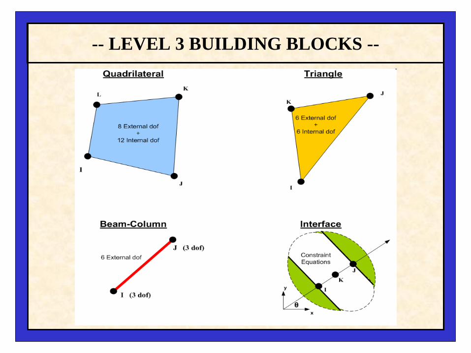
-- LEVEL 3 BUILDING BLOCKS --

-- LEVEL 3 EXAMPLE MESH --
Three reinforced/concrete arches (92’ span each)• 8,586 elements total
• 4 pipe groups including side tunnel
• 10 soil material zones including pile supports
• 12 construction increments plus live load

CANDE CAPABILITY OVERVIEW - 5
Major Input Selections (user choices)• Execution Mode – Analysis or Design
• Evaluation Method – Working stress or LRFD
• Pipe Type(s) – CMP, R/C and Plastic
• Solution Level – Level 1, 2 or 3
• System Choices – Soil models, interfaces, loading, etc.

- SYSTEM CHOICES -
Other major choices include:
1. Soil model choices:• Linear elastic (isotropic and orthotropic)
• Overburden dependent (canned and user supplied)
• Duncan/Selig soil models (canned and user supplied)
• Extended Hardin soil model (canned and user supplied)
2. Interface properties (angle, friction and tension)
3. Large deformation and buckling (on or off)
4. Nonlinear controls (iteration limit and bypass)

OVERVIEW COMPLETE
Next: LRFD Design Criteria and GUI Input
Then: GUI Output and Illustrations

Master

INTRODUCTION TO CAPABILITIES OF
CANDE-2007(Culvert ANalysis and DEsign)
August 5, 2009
Advanced Pipe ServicesAdvanced Pipe Services
Presented by:Tim Toliver, P.E.www.4pipe.com
TRB Webinar

8/6/2009
IntroductionOutput data and Viewing Options
• Graphical User Interface (GUI) output options • Files generated by CANDE• How to make a report based on FEA analysis
results. – View output report– Mesh generation– Graphical outputs
Most of the examples are from a project Dr. Katona and I worked on.

8/6/2009
Six Cases Analyzed
Case 6 - Damaged host pipe + plastic liner + fair grout
Case 3 - Damaged host pipe + plastic liner + fairgrout
Case 5 - Damaged host pipe + plastic liner + good grout
Case 2 - Damaged host pipe + plastic liner + good grout
Case 4 - Damaged host pipe onlyCase 1 - Damaged host pipe only
Poor Soil SeriesGood Soil Series
• Diameters 18” to 72” (total of 10 diameter)
• Dead Load
• Live Load
• Good Soil – 3,000 psi Modulus (125 pcf)
• Poor Soil – 1,000 psi Modulus (120 pcf)
• Good Grout – 70 pcf; 211,000 psi Modulus; 770 psi Strength
• Fair Grout – 40 pcf; 69,000 psi Modulus; 200 psi Strength

8/6/2009
File Generation
Input file
Typically begin with one input file

8/6/2009
File GenerationNew files after running input files
CID file is the input file and most critical.
All others may be deleted, however if deleted to view an output report you will need to re-run the input file.

8/6/2009
OUTPUT AND GUI
After running input file, open “View” tab shown below.
Key Selection Choices• Output Report (CANDE) – most comprehensive source of information
• Mesh plot – finite element mesh topology and stress/stain contours
• Graphs – Pipe-group plots of structural responses like moment diagrams

8/6/2009
OUTPUT REPORT CANDE
• Output report can be quite large depending upon mesh complexity and number of load steps.
• Interactive table contents locates data of interest and is divided into three parts:
• Master Control
• Input Data
• Output Data

8/6/2009
Output Report
• The .OUTfile is a word compatible file.• The .OUTfile can get very large• The preceding example had:
– 683 pages– 38,912 lines of text– 1,168,949 characters of text
• Minimizing the report and summarizing the results is important.

8/6/2009
Presenting Data• Rather than using the “.OUTfile”, you can
customize the report by using the results generator.– To start the results generator
• Select View>Output Generator (from the CANDE Toolbar).

8/6/2009
Customizing Report
• To further customize your report you can accomplished by cutting and pasting portions of the report.
• One easy way to do this is to use the interactive table of content to go directly to the are of interest in the report.
• Copy using the <control><C> command• Then insert text directly into a word
document.
8/6/2009
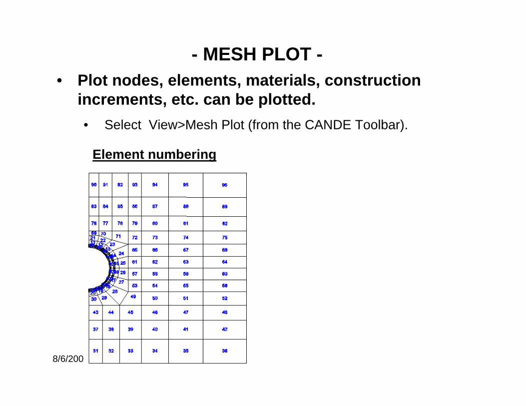
• Plot nodes, elements, materials, construction increments, etc. can be plotted. • Select View>Mesh Plot (from the CANDE Toolbar).
Element numbering
- MESH PLOT -

8/6/2009
Element numbering
- MESH PLOT -
Host Pipe
Interface
Grout
Interface
Liner
12
3
4
5
6
7
8
910
9798
99
100
101
102
103
104
105106
107 108109
110
111
112
113
114115
116
117 118
119
120
121
122
123
124
125
126127
128 129
130
131
132
133
134
135
136137138
Added Elements≅ Grout 97 – 106≅ Liner 107-116≅ Interface grout-host 117-127≅ Interface liner-grout 128-138
Element numbering
• At times the element numbering may be too close together or on top of each other in the case of interface elements.
• In the case of interface elements may be necessary to generate a second diagram to illustrate the element layout.

8/6/2009
Construction Increments
- MESH PLOT -
Backfill Materials
Other options include

8/6/2009
Mesh Plot Output• Plot can be customized using the Mesh viewer options
feature.
Mesh Viewer Options Button
specifies plotting
parameter

8/6/2009
Plot stress/strain color contours (vertical, horizontal shear)
- MESH PLOT (output) -
Vertical Strain

8/6/2009
GRAPHS FOR PIPE GROUPSPlot diagrams for moments, thrust, shears and many key responses

8/6/2009
Graph Properties Page
Graph properties page (right click on graph) can format you graphical presentation of the data.

Thank youfor Attending the TRB Webinar
INTRODUCTION TO CAPABILITIES OF CANDE-2007
(Culvert ANalysis and DEsign)
Advanced Pipe ServicesAdvanced Pipe Services
Presented by:Tim Toliver, P.E.www.4pipe.com
E-mail contact: [email protected]