high-speed input and pulse output features · pdf filehigh-speed input and pulse output...
TRANSCRIPT
13High-Speed Input andPulse Output Features
In This Chapter. . . .— Introduction— Choosing the HSIO Operating Mode— Mode 10: High-Speed Counter— Mode 20: Quadrature Counter— Mode 30: Pulse Output— Mode 40: High-Speed Interrupt— Mode 50: Pulse Catch Input— Mode 60: Filtered Inputs

High-Speed
Inputand
Pulse
OutputFeatures
3--2High-speed Input and Pulse Output Features
DL105 PLC User Manual, 3rd Edition
Introduction
Many machine control applicationsrequire various types of simplehigh-speedmonitoring and control. Theseapplications usually involve some type ofmotion control, or high-speed interruptsfor time-critical events. The DL105 MicroPLC solves this traditionally expensiveproblem with built-in CPU enhancements.Let’s take a closer look at the availablehigh-speed I/O features.
The available high-speed input features are:S High Speed Counter (5 kHz max.) with up to 24 counter presets and
built-in interrupt subroutine, counts up only, with resetS Quadrature encoder inputs to measure counts and clockwise or counter
clockwise direction (5 kHz max.), counts up or down, with resetS High-speed interrupt input for immediate response to critical or
time-sensitive tasksS Pulse catch feature to monitor one input point, having a pulse width as
small as 100μS (0.1ms)S Programmable discrete filtering (both on and off delay up to 99ms) to
ensure input signal integrity (this is the default mode for inputs X0--X3)The available pulse output features are:
S Single-axis programmable pulse output (7 kHz max.) with three profiletypes, including trapezoidal moves, registration, and velocity control
IMPORTANT: Please note the following restrictions on availability of features:S High-speed input options are available only on DL105s with DC inputs.S Pulse output options are available only on DL105s with DC outputs.S Only one HSIO feature may be in use at one time. You cannot use a
high--speed input feature and the pulse output at the same time.
DL105Part Number
DiscreteInput Type
DiscreteOutput Type
High-SpeedInput
PulseOutput
F1--130AR AC Relay No No
F1--130DR DC Relay Yes No
F1--130AD AC DC No Yes
F1--130DD DC DC Yes Yes
F1--130AA AC AC No No
F1--130DA DC AC Yes No
F1--130DR--D DC Relay Yes No
F1--130DD--D DC DC Yes Yes
Built-in MotionControl Solution
Availability ofHSIO Features
High-S
peedInputand
Pulse
OutputF
eatures3--3
High-Speed Input and Pulse Output Features
DL105 PLC User Manual, 3rd Edition
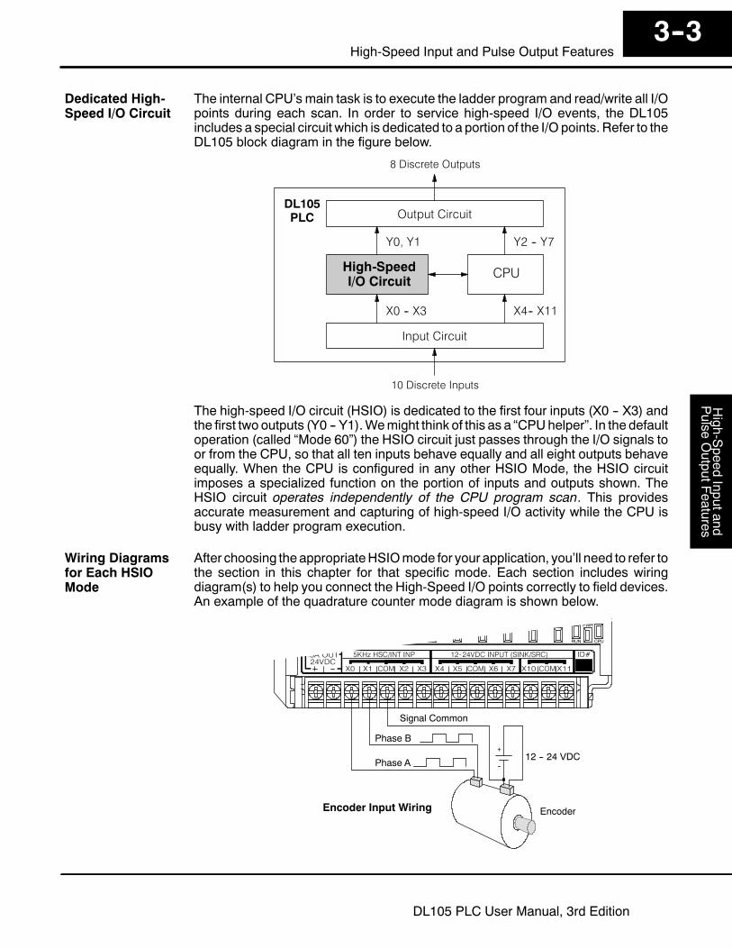
The internal CPU’s main task is to execute the ladder program and read/write all I/Opoints during each scan. In order to service high-speed I/O events, the DL105includes a special circuit which is dedicated to a portion of the I/O points. Refer to theDL105 block diagram in the figure below.
Output Circuit
Input Circuit
CPU
10 Discrete Inputs
8 Discrete Outputs
PLCDL105
High-SpeedI/O Circuit
X0 -- X3
Y0, Y1
X4-- X11
Y2 -- Y7
The high-speed I/O circuit (HSIO) is dedicated to the first four inputs (X0 -- X3) andthe first two outputs (Y0 -- Y1).Wemight think of this as a “CPUhelper”. In the defaultoperation (called “Mode 60”) the HSIO circuit just passes through the I/O signals toor from the CPU, so that all ten inputs behave equally and all eight outputs behaveequally. When the CPU is configured in any other HSIO Mode, the HSIO circuitimposes a specialized function on the portion of inputs and outputs shown. TheHSIO circuit operates independently of the CPU program scan. This providesaccurate measurement and capturing of high-speed I/O activity while the CPU isbusy with ladder program execution.
After choosing theappropriateHSIOmode for your application, you’ll need to refer tothe section in this chapter for that specific mode. Each section includes wiringdiagram(s) to help you connect the High-Speed I/O points correctly to field devices.An example of the quadrature counter mode diagram is shown below.
Encoder Input Wiring
+
--12 -- 24 VDC
Phase A
Phase B
Encoder
Signal Common
Dedicated High-Speed I/O Circuit
Wiring Diagramsfor Each HSIOMode
High-Speed
Inputand
Pulse
OutputFeatures
3--4High-speed Input and Pulse Output Features
DL105 PLC User Manual, 3rd Edition
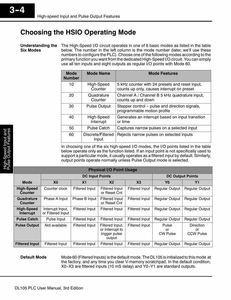
Choosing the HSIO Operating Mode
The High-Speed I/O circuit operates in one of 6 basic modes as listed in the tablebelow. The number in the left column is the mode number (later, we’ll use thesenumbers to configure the PLC). Choose one of the followingmodes according to theprimary function youwant from the dedicatedHigh-Speed I/O circuit. You can simplyuse all ten inputs and eight outputs as regular I/O points with Mode 60.
ModeNumber
Mode Name Mode Features
10 High-SpeedCounter
5 kHz counter with 24 presets and reset input,counts up only, causes interrupt on preset
20 QuadratureCounter
Channel A / Channel B 5 kHz quadrature input,counts up and down
30 Pulse Output Stepper control -- pulse and direction signals,programmable motion profile
40 High-SpeedInterrupt
Generates an interrupt based on input transitionor time
50 Pulse Catch Captures narrow pulses on a selected input
60 Discrete/FilteredInput
Rejects narrow pulses on selected inputs
In choosing one of the six high-speed I/O modes, the I/O points listed in the tablebelow operate only as the function listed. If an input point is not specifically used tosupport a particular mode, it usually operates as a filtered input by default. Similarly,output points operate normally unless Pulse Output mode is selected.
Physical I/O Point UsageDC Input Points DC Output Points
Mode X0 X1 X2 X3 Y0 Y1
High-SpeedCounter
Counter clock Filtered Input Filtered Inputor Reset Cnt
Filtered Input Regular Output Regular Output
QuadratureCounter
Phase A Input Phase B Input FIltered Inputor Reset Cnt
Filtered Input Regular Output Regular Output
High-SpeedInterrupt
Interrupt Input,or Filtered Input
Filtered Input Filtered Input Filtered Input Regular Output Regular Output
Pulse Catch Pulse Input Filtered Input Filtered Input Filtered Input Regular Output Regular Output
Pulse Output Not available Filtered Input Filtered Input,or Interrupt totrigger pulse
output
Filtered Input Pulseor
CW Pulse
Directionor
CCW Pulse
Filtered Input Filtered Input Filtered Input Filtered Input Filtered Input Regular Output Regular Output
Mode60 (Filtered Inputs) is the defaultmode. TheDL105 is initialized to thismode atthe factory, and any time you clear V-memory scratchpad. In the default condition,X0--X3 are filtered inputs (10 mS delay) and Y0--Y1 are standard outputs.
Understanding theSix Modes
Default Mode
High-S
peedInputand
Pulse
OutputF
eatures3--5
High-Speed Input and Pulse Output Features
DL105 PLC User Manual, 3rd Edition
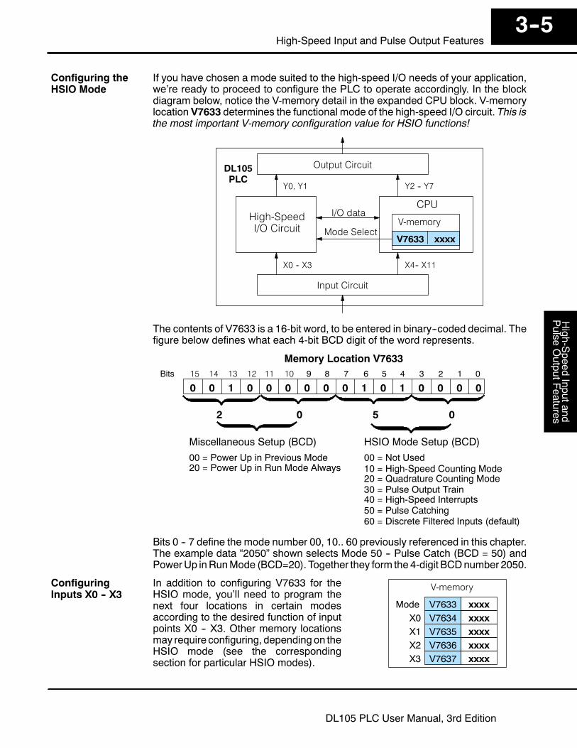
If you have chosen a mode suited to the high-speed I/O needs of your application,we’re ready to proceed to configure the PLC to operate accordingly. In the blockdiagram below, notice the V-memory detail in the expanded CPU block. V-memorylocation V7633 determines the functional mode of the high-speed I/O circuit. This isthe most important V-memory configuration value for HSIO functions!
Output Circuit
Input Circuit
CPU
PLCDL105
High-SpeedI/O Circuit
X0 -- X3
Y0, Y1
X4-- X11
Y2 -- Y7
V-memory
V7633 xxxxMode Select
I/O data
The contents of V7633 is a 16-bit word, to be entered in binary--coded decimal. Thefigure below defines what each 4-bit BCD digit of the word represents.
015 14 13 12
Memory Location V763311 10 123456789Bits
001 00010100
HSIO Mode Setup (BCD)Miscellaneous Setup (BCD)
0 0 0 0
00 = Power Up in Previous Mode20 = Power Up in Run Mode Always
00 = Not Used10 = High-Speed Counting Mode20 = Quadrature Counting Mode30 = Pulse Output Train
2 0 0
40 = High-Speed Interrupts50 = Pulse Catching60 = Discrete Filtered Inputs (default)
5
0
Bits 0 -- 7 define the mode number 00, 10.. 60 previously referenced in this chapter.The example data “2050” shown selects Mode 50 -- Pulse Catch (BCD = 50) andPowerUp inRunMode (BCD=20). Together they form the 4-digit BCDnumber 2050.
In addition to configuring V7633 for theHSIO mode, you’ll need to program thenext four locations in certain modesaccording to the desired function of inputpoints X0 -- X3. Other memory locationsmay require configuring, depending on theHSIO mode (see the correspondingsection for particular HSIO modes).
V-memory
V7633 xxxxModeV7634 xxxxX0V7635 xxxxX1V7636 xxxxX2V7637 xxxxX3
Configuring theHSIO Mode
ConfiguringInputs X0 -- X3
High-Speed
Inputand
Pulse
OutputFeatures
3--6High-speed Input and Pulse Output Features
DL105 PLC User Manual, 3rd Edition
Mode 10: High-Speed Counter
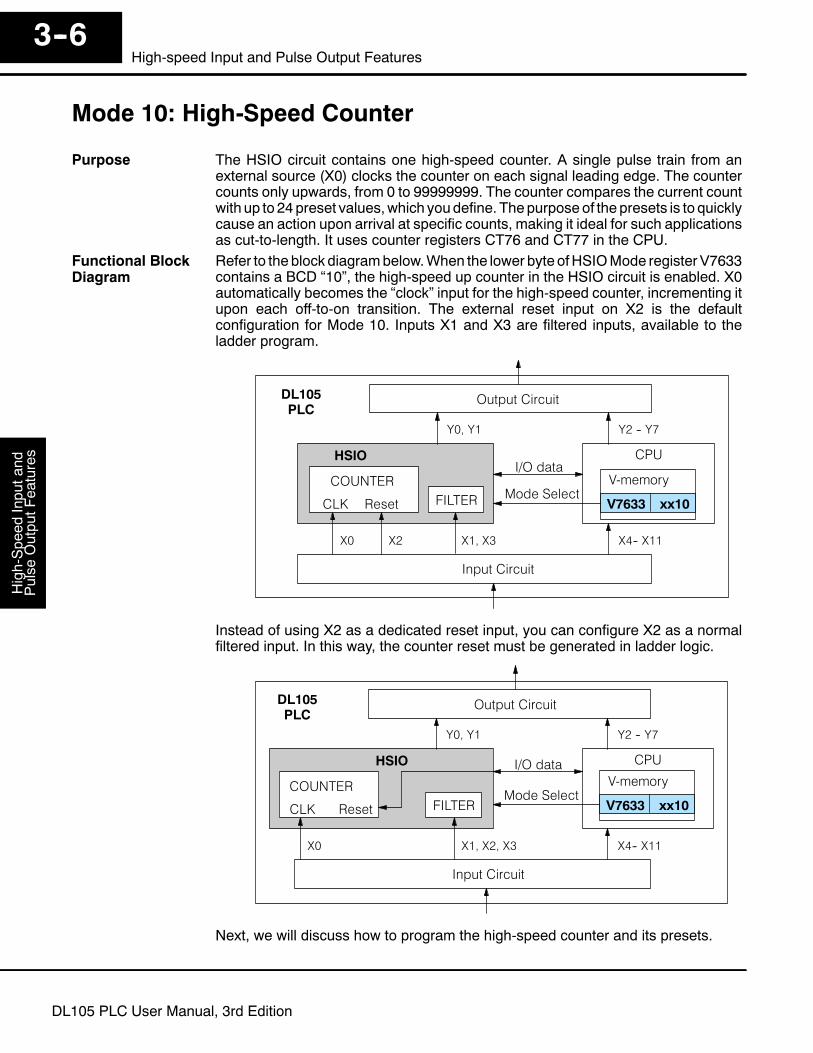
The HSIO circuit contains one high-speed counter. A single pulse train from anexternal source (X0) clocks the counter on each signal leading edge. The countercounts only upwards, from 0 to 99999999. The counter compares the current countwith up to 24preset values,which youdefine. Thepurpose of the presets is to quicklycause an action upon arrival at specific counts, making it ideal for such applicationsas cut-to-length. It uses counter registers CT76 and CT77 in the CPU.Refer to the block diagrambelow.When the lower byte ofHSIOMode registerV7633contains a BCD “10”, the high-speed up counter in the HSIO circuit is enabled. X0automatically becomes the “clock” input for the high-speed counter, incrementing itupon each off-to-on transition. The external reset input on X2 is the defaultconfiguration for Mode 10. Inputs X1 and X3 are filtered inputs, available to theladder program.
Output Circuit
Input Circuit
CPU
PLCDL105
X0
Y0, Y1
X4-- X11
Y2 -- Y7
V-memory
V7633 xx10Mode Select
I/O dataHSIO
COUNTER
CLK Reset
X2 X1, X3
FILTER
Instead of using X2 as a dedicated reset input, you can configure X2 as a normalfiltered input. In this way, the counter reset must be generated in ladder logic.
Output Circuit
Input Circuit
CPU
PLCDL105
X0
Y0, Y1
X4-- X11
Y2 -- Y7
V-memory
V7633 xx10Mode Select
I/O dataHSIO
COUNTER
CLK Reset
X1, X2, X3
FILTER
Next, we will discuss how to program the high-speed counter and its presets.
Purpose
Functional BlockDiagram

High-S
peedInputand
Pulse
OutputF
eatures3--7
High-Speed Input and Pulse Output Features
DL105 PLC User Manual, 3rd Edition
A general wiring diagram for counters/encoders to the DL105 in HSIO Mode 10 isshown below. Many types of pulse-generating devices may be used, such asproximity switches, single-channel encoders, magnetic or optical sensors, etc.Devices with sinking outputs (NPN open collector) are probably the best choice forinterfacing. If the counter sources to the inputs, it must output 12 to 24 VDC. Notethat devices with 5V sourcing outputs will not work with DL105 inputs.
Counter Input WiringSignal Common
Signal
The DL105’s DC inputs are flexible in that they detect current flow in either direction,so they can be wired to a counter with either sourcing or sinking outputs. In thefollowing circuit, a counter has open-collector NPN transistor outputs. It sinkscurrent from the PLC input point, which sources current. The power supply can bethe +24VDCauxiliary supply or another supply (+12VDCor +24VDC), as long as theinput specifications are met.
Counter Output
+--
X0 Input
Output
Ground
Input
Common
12-24 VDC Supply
(sinking) (sourcing)
In the next circuit, an encoder has open-emitter PNP transistor outputs. It sourcescurrent to the PLC input point, which sinks the current back to ground. Since theencoder sources current, no additional power supply is required. However, note thatthe encoder output must be 12 to 24 volts (5V encoder outputs will not work).
X0 Input
Output (sourcing)
Ground
Input
Common
+12 to 24VDC
(sinking)
Counter Output
Wiring Diagram
Interfacing toCounter Outputs

High-Speed
Inputand
Pulse
OutputFeatures
3--8High-speed Input and Pulse Output Features
DL105 PLC User Manual, 3rd Edition
Recall that V7633 is theHSIOModeSelect register. Refer to the diagrambelow.UseBCD 10 in the lower byte to select High-Speed Counter Mode. Use BCD 00 or 20 intheupper byte as required.Combine the twobytes into adataword “xx10”, forwritingto V7633.
015 14 13 12
Memory Location V763311 10 123456789Bits
001 00010000
HSIO Mode Setup (BCD)Miscellaneous Setup (BCD)
0 0 0 0
00 = Power Up in Previous Mode20 = Power Up in Run Mode Always 10 = High-Speed Counter
2 0 01
0
Choose the most convenient method of programming V7633 from the following:S Include load and out instructions in your ladder programS DirectSOFT’s memory editorS Use the Handheld Programmer D2--HPP
We recommend using the first method above so that the HSIO setup becomes anintegral part of your application program. An example program later in this sectionshows how to to this.The goal of counting is to do a special actionwhen the count reaches a preset value.Refer to the figure below. The counter features 24 presets, which you can program.Apreset is a number you derive and store so that the counterwill constantly comparethe current count with the preset. When the two are equal, a special relay contact isenergized and program execution jumps to the interrupt routine. We recommendusing the special relay(s) in the interrupt service routine to cause any immediateaction you desire. After the interrupt service routine is complete, the CPU returns tothe ladder program, resuming program execution from the point of interruption. Thecompare function is ready for the next preset event.
X0, counter clock
CPU Scan
Counter
Reset
X2, external reset
Current
Value
V-memory Preset Data
V2320 0000V2322 0000V2324 0000V2326 0000
1000200025003175
V2376 0921 0000
InputUpdate
LadderProgramExecution
OutputUpdate
DoesCount =Preset?
SPxxx
INT
HSIOInterruptRoutineProgram
IRT
=
Currentinstruction
Setup for Mode 10
Presets andSpecial Relays

High-S
peedInputand
Pulse
OutputF
eatures3--9
High-Speed Input and Pulse Output Features
DL105 PLC User Manual, 3rd Edition
V7630 is a pointer location which points tothe beginning of the Preset Data Table.The default starting location for the PresetData Table is V2320 (default afterinitializing scratchpad V-memory).However, you may change this byprogramming a different value in V7630.Use the LDA and OUT instructions asshown:
Preset Data
V2000 0000V2002 0000V2004 0000V2006 0000
1000200025003175
V2076 0000 0000
V7630 2000
Preset Table Pointer
LDAO2000
Load the octal address,convert to hex, leaveresult in accumulator.
OUTV7630
Output this address toV7630, the location of thepointer to the Preset data.
When using fewer than 24 presetregisters, the HSIO looks for “0000 FFFF”(use LDD Kffff) in the next preset locationto indicate the last preset has beenreached. The example to the right usesfour presets. The 0000 FFFF inV2331-V2330 indicates the previouspreset was the last.
Preset Data
V2320 0000V2322 0000V2324 0000V2326 0000
1000200025003175
V2330 0000 FFFF
NOTE: Each successive preset must be greater than the previous preset value. If apreset value is less than a lower-numbered preset value, the CPU cannot comparefor that value, since the counter can only count upwards.
The following table lists all 24 preset register default locations. Each occupies two16-bit V-memory registers. The corresponding special relay contact number is in thenext column. Wemight also call these “equal” relay contacts, because they are true(closed) when the present high-speed counter value is equal to the preset value.Each contact remains closed until the counter value equals the next preset value.
Preset PresetV-memory Regis-
ter
SpecialRelayNumber
Preset PresetV-memory Regis-
ter
SpecialRelayNumber
1 V2321 / V2320 SP540 13 V2351 / V2350 SP554
2 V2323 / V2322 SP541 14 V2353 / V2352 SP555
3 V2325 / V2324 SP542 15 V2355 / V2354 SP556
4 V2327 / V2326 SP543 16 V2357 / V2356 SP557
5 V2331 / V2330 SP544 17 V2361 / V2360 SP560
6 V2333 / V2332 SP545 18 V2363 / V2362 SP561
7 V2335 / V2334 SP546 19 V2365 / V2364 SP562
8 V2337 / V2336 SP547 20 V2367 / V2366 SP563
9 V2341 / V2340 SP550 21 V2371 / V2370 SP564
10 V2343 / V2342 SP551 22 V2373 / V2372 SP565
11 V2345 / V2344 SP552 23 V2375 / V2374 SP566
12 V2347 / V2346 SP553 24 V2377 / V2376 SP567
Preset DataStarting Location
Using Fewer than24 Presets
Equal RelayNumbers

High-Speed
Inputand
Pulse
OutputFeatures
3--10High-speed Input and Pulse Output Features
DL105 PLC User Manual, 3rd Edition
The preset values occupy two data words each. They can range in value from 00000000 to 9999 9999, just like the high-speed counter value. All twenty-four values areabsolute values, meaning that each one is an offset from the counter zero value.The preset values must be individually derived for each application. In the industriallathe diagram below, the PLC monitors the position of the lead screw by countingpulses. At points A, B, and C along the linear travel, the cutter head pushes into thework material and cuts a groove.
PLCIndustrial Lathe
Start
A B C
CounterDevice
X0, counter clock
Motor
The timing diagram below shows the duration of each equal relay contact closure.Each contact remains on until the next one closes. All go off when the counter resets.
Equal Relays
SP540
SP541
SP542
A B C
NOTE: Each successive preset must have a greater value than the previous presetvalue. In the industrial lathe example, B > A and C > B.
The configurable discrete input options for High-Speed Counter Mode are listed inthe table below. Input X0 is dedicated for the counter clock input. Inputs X1 and X3can only be filtered inputs. The section on Mode 60 operation at the end of thischapter describes programming the filter time constants. Input X2 can be configuredas the counter reset, with or without the interrupt option. The interrupt option allowsthe reset input (X2) to cause an interrupt like presets do, but there is no SP relaycontact closure (instead, X2 will be on during the interrupt routine, for 1 scan). Orfinally, X2 may be left simply as a filtered input like X1 and X3.
Input ConfigurationRegister
Function Hex CodeRequired
X0 V7634 Counter Clock 0001
X1 V7635 Filtered Input xx06 (xx = filter time)
X2 V7636 Counter Reset (no interrupt) 0007
Counter Reset (with interrupt) 0107
FIltered Input xx06 (xx = filter time)
X3 V7637 FIltered Input xx06 (xx = filter time)
Calculating YourPreset Values
X InputConfiguration
High-S
peedInputand
Pulse
OutputF
eatures3--11
High-Speed Input and Pulse Output Features
DL105 PLC User Manual, 3rd Edition
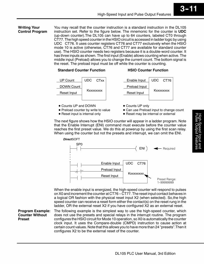
You may recall that the counter instruction is a standard instruction in the DL105instruction set. Refer to the figure below. The mnemonic for the counter is UDC(up-down counter).The DL105 can have up to 64 counters, labeled CT0 throughCT77. Thehigh speed counter in theHSIOcircuit is accessed in ladder logic byusingUDC CT76. It uses counter registers CT76 and CT77 exclusively when the HSIOmode 10 is active (otherwise, CT76 and CT77 are available for standard counteruse). The HSIO counter needs two registers because it is a double-word counter. Ithas three inputs as shown. The first input (Enable) allows countingwhen active. Themiddle input (Preload) allows you to change the current count. The bottom signal isthe reset. The preload input must be off while the counter is counting.
Reset Input
UDC CT76
Kxxxxxxxx
Enable Input
Preload Input
Reset Input
UDC CTxx
Kxxxxxxxx
UP Count
DOWN Count
Standard Counter Function HSIO Counter Function
D Counts UP and DOWN D Counts UP only
D Reset input is internal only D Reset may be internal or externalD Preload counter by write to value D Can use Preload input to change count
The next figure shows how the HSIO counter will appear in a ladder program. Notethat the Enable Interrupt (ENI) command must execute before the counter valuereaches the first preset value. We do this at powerup by using the first scan relay.When using the counter but not the presets and interrupt, we can omit the ENI.
DirectSOFT
Required
Preset Range:1--99999999
Reset Input
UDC CT76
Kxxxxxxxx
Enable Input
Preload Input
ENISP0
When the enable input is energized, the high-speed counter will respond to pulsesonX0and increment the counter atCT76 -- CT77. The reset input contact behaves ina logical OR fashion with the physical reset input X2 (when selected). So,the highspeed counter can receive a reset form either the contact(s) on the reset rung in theladder, OR the external reset X2 if you have configured X2 as an external reset.The following example is the simplest way to use the high-speed counter, whichdoes not use the presets and special relays in the interrupt routine. The programconfigures theHSIOcircuit forMode10operation, soX0 is automatically the counterclock input. It uses the Compare-double (CMPD) instruction to cause action atcertain count values.Note that this allows you to havemore than 24 “presets”.Then itconfigures X2 to be the external reset of the counter.
Writing YourControl Program
Program Example:Counter WithoutPreset

High-Speed
Inputand
Pulse
OutputFeatures
3--12High-speed Input and Pulse Output Features
DL105 PLC User Manual, 3rd Edition
SP0LDK10
Load constant K10 into the accumulator. Thisselects Mode 10 as the HSIO mode.
OUTV7633
Output the constant K10 to V7633, thelocation of HSIO Mode select register.
LDK1
Load the constant required to configure X0 asthe counter clock.
OUTV7634
Output the constant K1 to V7634, the location ofthe setup parameter for X0.
First Scan Only
DirectSOFT
UDC CT76
KxxxxxxxxSP1
SP1
SP1
END END coil marks the end of the main program.
CT76 is the HSIO counter. The first rung’s SP1always enables the counter. The preload contact inthe middle is always off. The third rung’s Resetinput is always off, because we will use theexternal reset.
LDK7
Load the constant required to configure X2 asan external reset without interrupt.
OUTV7636
Output the constant K7 to V7636, the location ofthe setup parameter for X2.
LDK1006
Load the constant required to configure inputsas filtered inputs.
OUTV7635
Output the constant K1006 to V7635, the locationof setup parameter for X1.
OUTV7637
Output the constant K1006 to V7637, the locationof setup parameter for X3.
Mode 10
ConfigureInputs
SP1LDDV1076
Load the current count of the HSIO counter inV1076 and V1077 into the accumulator
CMPDK309482
Use the Compare-double instruction to comparethe double word in the accumulator to the constantK309482
SP62
OUT The execution of the above CMPD instruction turnson special relay contact SP62 if the current countis greater than the comparison number (K309482).
Y0
The compare double instruction above uses the current count of theHSIOcounter toturn on Y0. This technique can make more than 24 comparisons, but it is scan-timedependent. However, use the 24 built-in presets with the interrupt routine if yourapplication needs a very fast response time, as shown in the next example.
ProgramExample Cont’d

High-S
peedInputand
Pulse
OutputF
eatures3--13
High-Speed Input and Pulse Output Features
DL105 PLC User Manual, 3rd Edition
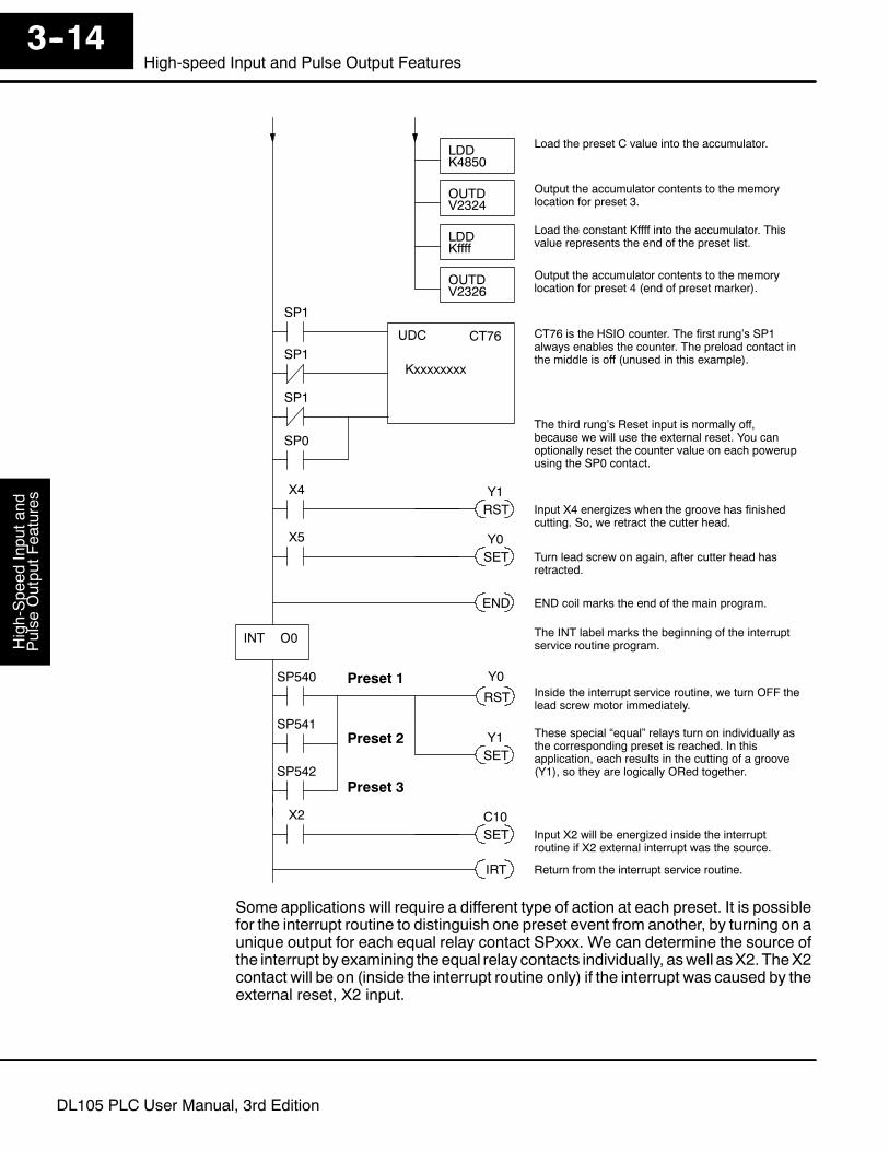
The following example shows how to program the HSIO circuit to trigger on threepreset values. Youmay recall the industrial lathe example from the beginning of thischapter. This example program shows how to control the lathe cutter head to makethree grooves in the work-piece at precise positions.When the lead screw turns, thecounter device generates pulses which the DL105 can count. The three presetvariables A, B, and C represent the positions (number of pulses) corresponding toeach of the three grooves.
Industrial Lathe
Counter
A
Preset Data V2320 0000V2322 0000V2324 0000V2326 0000
150037804850FFFF
B C
ABC
Device StartLead screwCutter head
X5 -- Cutter head retractedY0 -- Lead screw motorY1 -- Cutter head solenoid
X4 -- Cutter head extendedI/OAssignments
SP0LDK10
Load constant K10 into the accumulator. Thisselects Mode 10 as the HSIO mode.
OUTV7633
Output this address to V7633, the location ofHSIO Mode select register.
LDK107
Load the constant required to configure X2 asan external reset with interrupt.
OUTV7636
Output the constant to V7636, the location of thesetup parameter for X2.
Select Mode 10
DirectSOFTSP0
ENIEnable Interrupts before reaching a presetgenerates an interrupt. Special Relay SP0 is onduring the first CPU scan.
LDDK1500
Load the preset A value into the accumulator.
OUTDV2320
Output the accumulator contents to the memorylocation for preset 1.
LDDK3780
Load the preset B value into the accumulator.
OUTDV2322
Output the accumulator contents to the memorylocation for preset 2.
Load Presets
SP0
LDAO2320
Load the octal address O2320 into theaccumulator. This instruction automaticallyconverts the address into hex.
OUTV7630
Output this address to V7630, the location ofthe pointer to the Preset Table.
LDK1
Load the constant required to configure X0 asthe counter clock.
OUTV7634
Output the constant K1 to V7634, the location ofthe setup parameter for X0.
Counter WithPresetsProgram Example
High-Speed
Inputand
Pulse
OutputFeatures
3--14High-speed Input and Pulse Output Features
DL105 PLC User Manual, 3rd Edition
UDC CT76
KxxxxxxxxSP1
SP1
SP1
END END coil marks the end of the main program.
INT O0
CT76 is the HSIO counter. The first rung’s SP1always enables the counter. The preload contact inthe middle is off (unused in this example).
IRT Return from the interrupt service routine.
Y0SP540Inside the interrupt service routine, we turn OFF thelead screw motor immediately.
The INT label marks the beginning of the interruptservice routine program.
RST
X4
RST Input X4 energizes when the groove has finishedcutting. So, we retract the cutter head.
Y1
X5
SET Turn lead screw on again, after cutter head hasretracted.
Y0
LDDK4850
Load the preset C value into the accumulator.
OUTDV2324
Output the accumulator contents to the memorylocation for preset 3.
LDDKffff
Load the constant Kffff into the accumulator. Thisvalue represents the end of the preset list.
OUTDV2326
Output the accumulator contents to the memorylocation for preset 4 (end of preset marker).
SP541
SP542
These special “equal” relays turn on individually asthe corresponding preset is reached. In thisapplication, each results in the cutting of a groove(Y1), so they are logically ORed together.
Preset 1
Preset 2
Preset 3
SETY1
SP0
X2
SET Input X2 will be energized inside the interruptroutine if X2 external interrupt was the source.
C10
The third rung’s Reset input is normally off,because we will use the external reset. You canoptionally reset the counter value on each powerupusing the SP0 contact.
Some applications will require a different type of action at each preset. It is possiblefor the interrupt routine to distinguish one preset event from another, by turning on aunique output for each equal relay contact SPxxx. We can determine the source ofthe interrupt by examining theequal relay contacts individually, aswell asX2. TheX2contact will be on (inside the interrupt routine only) if the interrupt was caused by theexternal reset, X2 input.

High-S
peedInputand
Pulse
OutputF
eatures3--15
High-Speed Input and Pulse Output Features
DL105 PLC User Manual, 3rd Edition
The following example shows how you can preload the current count with anothervalue. When the preload command input (X4 in this example) is energized, wedisable the counter from counting with C0. Then we write the value K3000 to thecount register (V1076-V1077). By pulsingC1 on, we preload the current count of thecounter with K3000. When the preload command (X4) is turned off, the counterresumes counting any pulses, but now starting from K3000.
SP0LDK10
Load constant K10 into the accumulator. Thisselects Mode 10 as the HSIO mode.
OUTV7633
Output this address to V7633, the location ofHSIO Mode select register.
LDK107
Load the constant required to configure X2 asan external reset with interrupt.
OUTV7636
Output the constant to V7636, the location of thesetup parameter for X2.
Select Mode 10
DirectSOFT
SET Set C0 on at powerup to enable counting.C0
X4
RST
When the preload request is made, the user turnson X4. First we disable counting by resetting C0,the counter’s enable input.
UDC CT76
K99999999C1
C0
C2
CT76 is the HSIO counter. The first rung’s C0contact enables the counter. The preload contactin the middle is off until the logic near the end ofthis program turns it on.
C0
PDGenerate a preload counter input pulse, whichcauses the counter to preload from V1076-V1077.
C1
SP0
LDDK3000
Load the BCD value K3000 into theaccumulator.
OUTDV1076
Output the constant to V1076/V1077, the locationof the accumulated count for CT76.
END END coil marks the end of the main program.
C1C0
SETC0
Enable the counter by setting C0, when thepreolad pulse on C1 has occurred (C1 is off).
LDK1
Load the constant required to configure X0 asthe counter clock.
OUTV7634
Output the constant K1 to V7634, the location ofthe setup parameter for X0.
The third rung’s Reset input is normally off,because we will use the external reset. You canoptionally reset the counter value on each powerupusing the SP0 contact.
Counter WithPreloadProgram Example

High-Speed
Inputand
Pulse
OutputFeatures
3--16High-speed Input and Pulse Output Features
DL105 PLC User Manual, 3rd Edition
If you’re having trouble with Mode 10 operation, please study the followingsymptoms and possible causes. The most common problems are listed below.
Symptom: The counter does not count.Possible causes:
1. Field sensor and wiring -- Verify that the encoder, proximity switch,orcounter actually turns on and illuminates the status LED for X0. Theproblem could be due to sinking-sourcing wiring problem, etc. Rememberto check the signal ground connection. Also verify that the pulse on-time islong enough for the PLC to recognize it.
2. Configuration -- make sure all of the configuration parameters are correct.V7633 must be set to 10, and V7634 must be set to 1 to enable the HSIOcounter mode.
3. Stuck in reset -- check the input status of the reset input, X2. If X2 is on, thecounter will not count because it is being held in reset.
4. Ladder program -- make sure you are using counter CT76 in yourprogram. The top input is the enable signal for the counter. It must be onbefore the counterwill count. Themiddle input is the preload input andmustbe off for the counter to count. The bottom input is the counter reset, andmust be off during counting.
Symptom: The counter counts but the presets do not function.Possible causes:
1. Configuration -- Ensure the preset values are correct. The presets are32-bit BCDvalues having a range of 0 to 99999999.Make sure youwrite all32 bits to the reserved locations by using the LDD and OUTD instructions.Use only even--numbered addresses, from V2320 to V2376. If using lessthan 24 presets, be sure to place “0000FFFF” in the location after the lastpreset used.
2. Interrupt routine -- Only use Interrupt #0.Make sure the interrupt has beenenabled by executing an ENI instruction prior to needing the interrupt. Theinterrupt routinemust be placed after themain program, using the INT labeland ending with an interrupt return IRT.
3. Special relays -- Check the special relay numbers in your program. UseSP540 for Preset 1, SP541 for Preset 2, etc. Remember that only onespecial equal relay contact is on at a time.When the counter value reachesthe next preset, the SP contact which is on now goes off and the next oneturns on.
Symptom: The counter counts up but will not reset.Possible causes:
1. Check the LED status indicator for X2 to make sure it is active when youwant a reset. Or, if you are using an internal reset, use the status mode ofDirectSOFT to monitor the reset input to the counter.
TroubleshootingGuide for Mode 10

High-S
peedInputand
Pulse
OutputF
eatures3--17
High-Speed Input and Pulse Output Features
DL105 PLC User Manual, 3rd Edition
Mode 20: Quadrature Counter
The counter in the HSIO circuit can count two quadrature signal pulses instead of asingle pulse train (mode10operation).Quadrature signals are commonly generatedfrom incremental encoders, which may be rotary or linear. The quadrature counterhas a range from0 to 99999999, and can count at up to a 5 kHz rate, usingCT76 andCT77. Unlike Mode 10 operation, the quadrature counter can count UP or DOWN,but does not feature automated preset values or “interrupt on external reset”capability. However, you have the standard ladder instruction preset of CT76.The diagram below shows HSIO functionality in Mode 20. When the lower byte ofHSIOMode register V7633 contains aBCD “20”, the quadrature counter in theHSIOcircuit is enabled. Input X0 is dedicated to the Phase A quadrature signal, and inputX1 receives Phase B signal. X2 is dedicated to reset the counter to zero value whenenergized. X3 can only be a regular filtered input in Mode 20.
Output Circuit
Input Circuit
CPU
PLCDL105
X0
Y0, Y1
X4-- X11
Y2 -- Y7
V-memory
V7633 xx20Mode Select
I/O dataHSIO
COUNTER
PhaseA
PhaseB
X2 X3
Reset
X1
FILTER
Quadrature encoder signals contain position and direction information, while theirfrequency represents speed of motion. Phase A and B signals shown below arephase-shifted 90 degrees, thus the quadrature name. When the rising edge ofPhase A precedes Phase B’s leading edge (indicates clockwise motion byconvention), the HSIO counter counts UP. If Phase B’s rising edge precedes PhaseA’s rising edge (indicates counter-clockwise motion), the counter counts DOWN.
90° phase shift
Phase A
Phase B
Leading Edge Signal
Phase A
Phase B
Leading Edge Signal
Clockwise sequence
Counterclockwise sequence
one cycle
Purpose
Functional BlockDiagram
QuadratureEncoder Signals

High-Speed
Inputand
Pulse
OutputFeatures
3--18High-speed Input and Pulse Output Features
DL105 PLC User Manual, 3rd Edition
A general wiring diagram for encoders to the DL105 in HSIO Mode 20 is shownbelow. Encoders with sinking outputs (NPN open collector) are probably the bestchoice for interfacing. If the encoder sources to the inputs, it must output 12 to 24VDC. Note that encoders with 5V sourcing outputs will not work with DL105 inputs.
Encoder Input Wiring
+
--DC Supply
Phase A
Phase B
Encoder
Signal Common
The DL105’s DC inputs are flexible in that they detect current flow in either direction,so they can be wired to an encoder with either sourcing or sinking outputs. In thefollowing circuit, an encoder has open-collector NPN transistor outputs. It sinkscurrent from the PLC input point, which sources current. The power supply can bethe +24VDCauxiliary supply or another supply (+12VDCor +24VDC), as long as theinput specifications are met.
Encoder Output,(one phase)
+--
Phase A or B Input
Output
Ground
Input
Common
12-24 VDC Supply
(sinking) (sourcing)
In the next circuit, an encoder has open-emitter PNP transistor outputs. It sourcescurrent to the PLC input point, which sinks the current back to ground. Since theencoder sources current, no additional power supply is required. However, note thatthe encoder output must be 12 to 24 volts (5V encoder outputs will not work).
Phase A or B Input
Output (sourcing)
Ground
Input
Common
+12 to 24VDC
(sinking)
Encoder Output,(one phase)
Wiring Diagram
Interfacing toEncoder Outputs
High-S
peedInputand
Pulse
OutputF
eatures3--19
High-Speed Input and Pulse Output Features
DL105 PLC User Manual, 3rd Edition
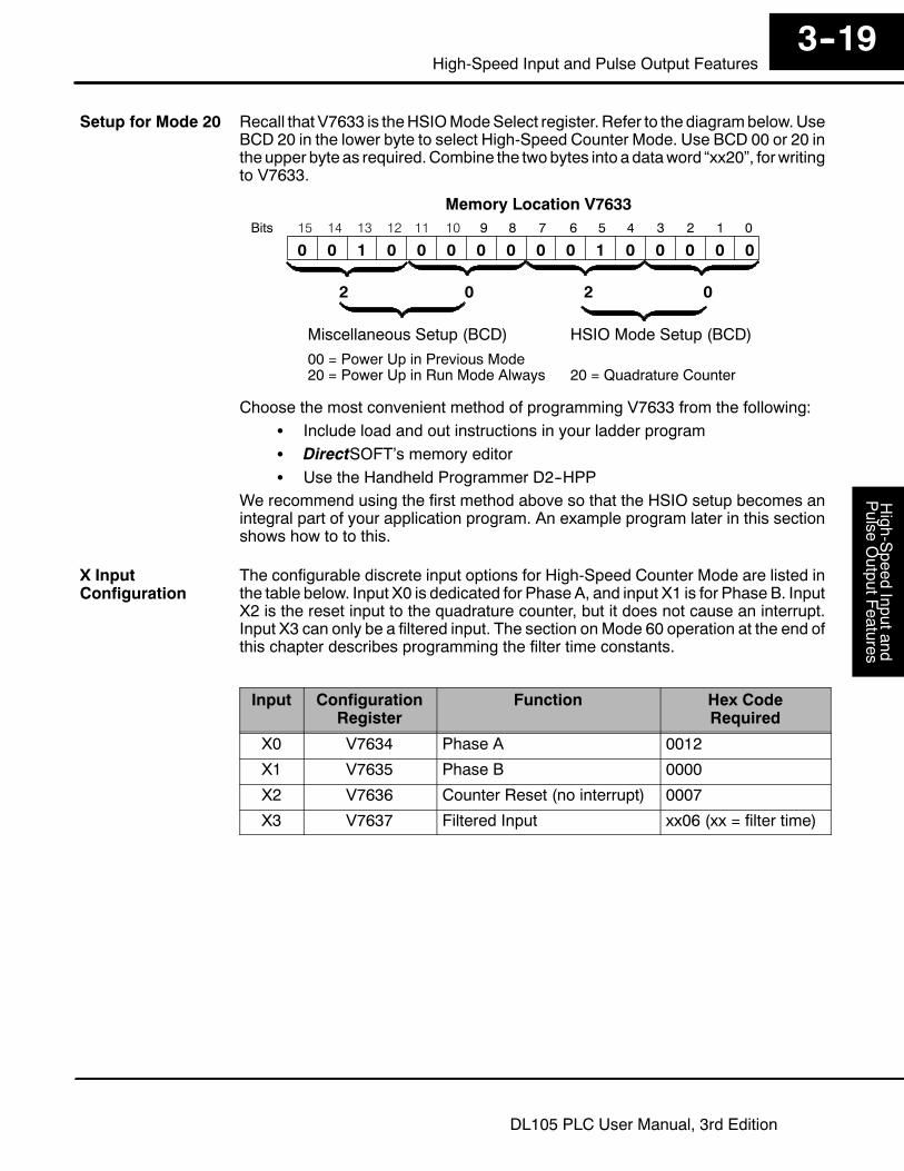
Recall that V7633 is theHSIOModeSelect register. Refer to the diagrambelow.UseBCD 20 in the lower byte to select High-Speed Counter Mode. Use BCD 00 or 20 intheupper byte as required.Combine the twobytes into adataword “xx20”, forwritingto V7633.
015 14 13 12
Memory Location V763311 10 123456789Bits
001 00001000
HSIO Mode Setup (BCD)Miscellaneous Setup (BCD)
0 0 0 0
00 = Power Up in Previous Mode20 = Power Up in Run Mode Always 20 = Quadrature Counter
2 0 02
0
Choose the most convenient method of programming V7633 from the following:S Include load and out instructions in your ladder programS DirectSOFT’s memory editorS Use the Handheld Programmer D2--HPP
We recommend using the first method above so that the HSIO setup becomes anintegral part of your application program. An example program later in this sectionshows how to to this.
The configurable discrete input options for High-Speed Counter Mode are listed inthe table below. Input X0 is dedicated for Phase A, and input X1 is for Phase B. InputX2 is the reset input to the quadrature counter, but it does not cause an interrupt.Input X3 can only be a filtered input. The section onMode 60 operation at the end ofthis chapter describes programming the filter time constants.
Input ConfigurationRegister
Function Hex CodeRequired
X0 V7634 Phase A 0012
X1 V7635 Phase B 0000
X2 V7636 Counter Reset (no interrupt) 0007
X3 V7637 Filtered Input xx06 (xx = filter time)
Setup for Mode 20
X InputConfiguration

High-Speed
Inputand
Pulse
OutputFeatures
3--20High-speed Input and Pulse Output Features
DL105 PLC User Manual, 3rd Edition
You may recall that the Up-Down counter instruction is standard in the DL105instruction set. Refer to the figure below. The mnemonic for the counter is UDC(up-down counter).The DL105 can have up to 64 counters, labeled CT0 throughCT77. The quadrature counter in the HSIO circuit is accessed in ladder logic byusing UDC CT76. It uses counter registers CT76 and CT77 exclusively when theHSIO mode 20 is active (otherwise, CT76 and CT77 are available for standardcounter use). The HSIO counter needs two registers because it is a double-wordcounter. It also has three inputs as shown, but they are redefined. The first input isthe enable signal, the middle is a preload (write), and the bottom is the reset. Theenable input must be on before the counter will count. The preload input allows youto write a new value to the current count. The enable input must be off during apreload.
Reset Input
UDC CT76
Kxxxxxxxx
Enable Input
Preload Input
Reset Input
UDC CTxx
Kxxxxxxxx
UP Count
DOWN Count
Standard Counter Function HSIO Counter Function
D Counts UP and DOWN D Counts UP and DOWN (from X0, X1)
D Reset input is internal only D Reset may be internal or externalD Preload counter by write to value D Can use Preload input to change count
The next figure shows the how the HSIO quadrature counter will appear in a ladderprogram.
Preset Range:--8,388,608 to+8,388,607
Reset Input
UDC CT76
Kxxxxxxxx
Enable Input
Preload Input
When the enable input is energized, the counter will respond to quadrature pulseson X0 and X1, incrementing or decrementing the counter at CT76 -- CT77. The resetinput contact behaves in a logical OR fashion with the physical reset input X2. Thismeans the quadrature counter can receive a reset from either the contact(s) on thereset rung in the ladder, OR the external reset X2.
Since presets are not available in quadrature counting, this mode is best suited forsimple counting andmeasuring. The example programon the following page showshow to configure the quadrature counter. The program configures the HSIO circuitfor Mode 20 operation, so X0 is Phase A and X1 is Phase B clock inputs.
Writing YourControl Program
QuadratureCounter w/PreloadProgram Example
High-S
peedInputand
Pulse
OutputF
eatures3--21
High-Speed Input and Pulse Output Features
DL105 PLC User Manual, 3rd Edition
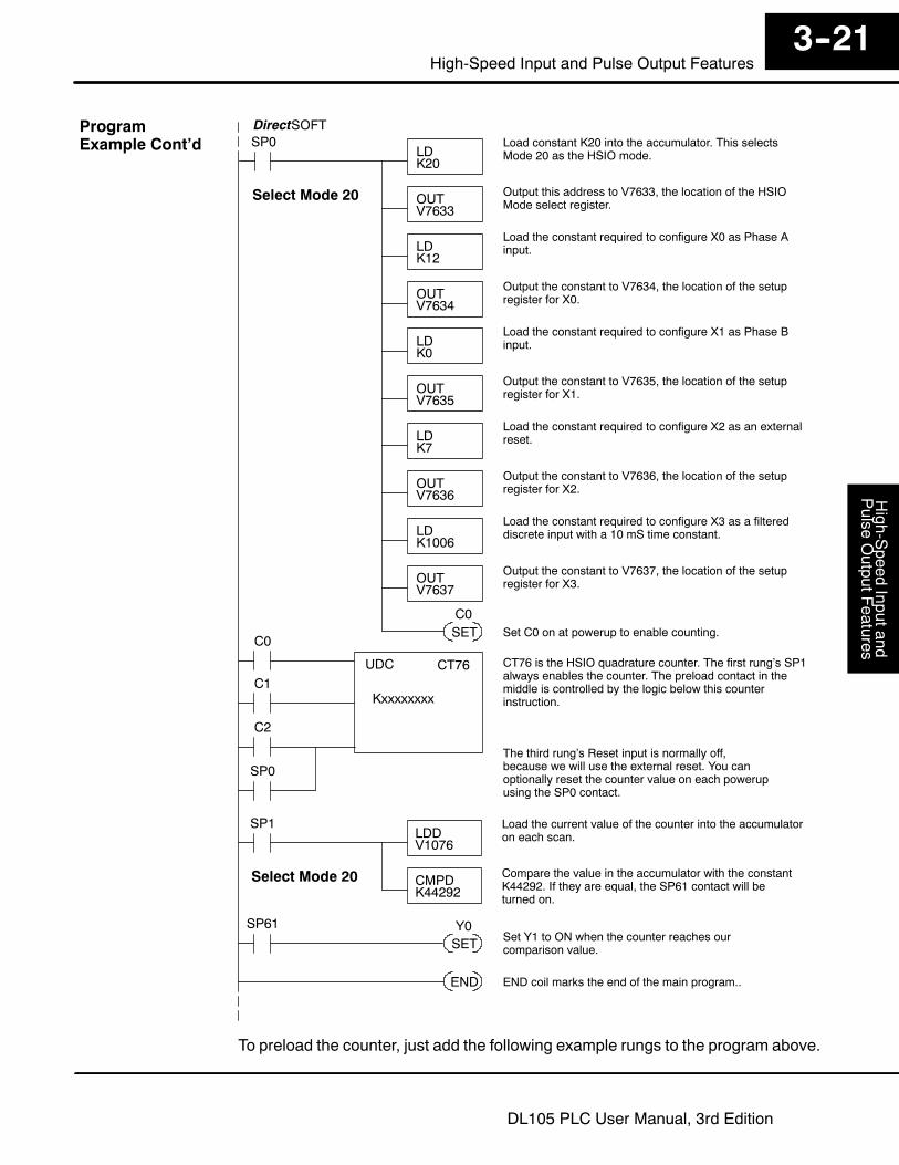
SP0LDK20
Load constant K20 into the accumulator. This selectsMode 20 as the HSIO mode.
OUTV7633
Output this address to V7633, the location of the HSIOMode select register.
LDK12
Load the constant required to configure X0 as Phase Ainput.
OUTV7634
Output the constant to V7634, the location of the setupregister for X0.
DirectSOFT
UDC CT76
KxxxxxxxxC1
C0
C2
END END coil marks the end of the main program..
CT76 is the HSIO quadrature counter. The first rung’s SP1always enables the counter. The preload contact in themiddle is controlled by the logic below this counterinstruction.
LDK0
Load the constant required to configure X1 as Phase Binput.
OUTV7635
Output the constant to V7635, the location of the setupregister for X1.
LDK7
Load the constant required to configure X2 as an externalreset.
OUTV7636
Output the constant to V7636, the location of the setupregister for X2.
LDK1006
Load the constant required to configure X3 as a filtereddiscrete input with a 10 mS time constant.
OUTV7637
Output the constant to V7637, the location of the setupregister for X3.
SET Set C0 on at powerup to enable counting.C0
SP0
Select Mode 20
The third rung’s Reset input is normally off,because we will use the external reset. You canoptionally reset the counter value on each powerupusing the SP0 contact.
SP1LDDV1076
Load the current value of the counter into the accumulatoron each scan.
CMPDK44292
Compare the value in the accumulator with the constantK44292. If they are equal, the SP61 contact will beturned on.
Select Mode 20
SP61
SETY0
Set Y1 to ON when the counter reaches ourcomparison value.
To preload the counter, just add the following example rungs to the program above.
ProgramExample Cont’d
High-Speed
Inputand
Pulse
OutputFeatures
3--22High-speed Input and Pulse Output Features
DL105 PLC User Manual, 3rd Edition
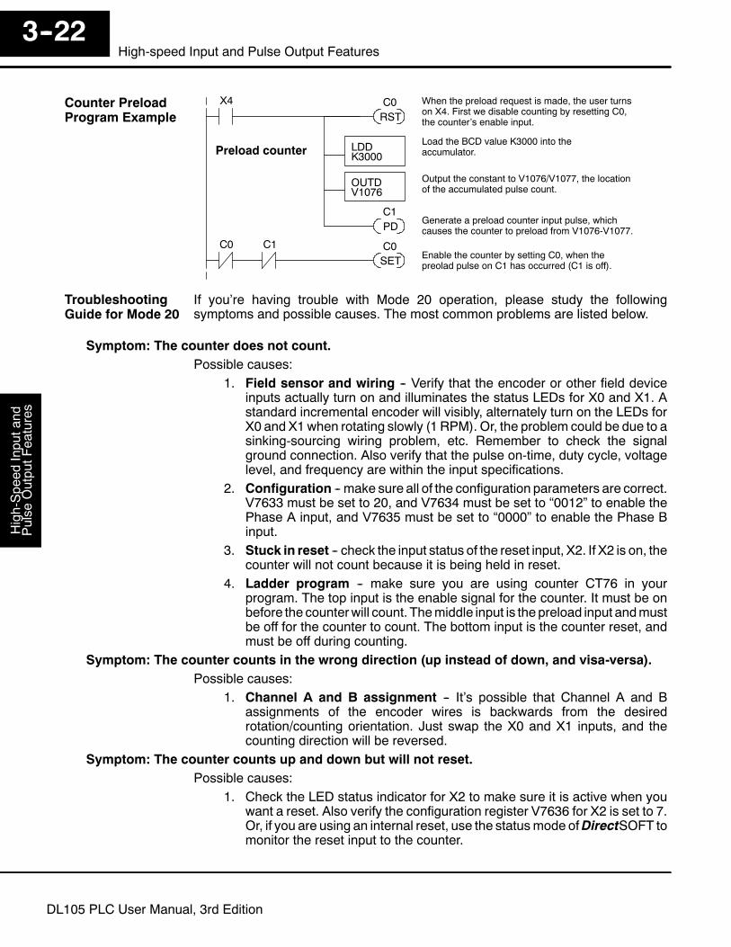
X4
RST
When the preload request is made, the user turnson X4. First we disable counting by resetting C0,the counter’s enable input.
C0
PDGenerate a preload counter input pulse, whichcauses the counter to preload from V1076-V1077.
C1
LDDK3000
Load the BCD value K3000 into theaccumulator.
OUTDV1076
Output the constant to V1076/V1077, the locationof the accumulated pulse count.
Preload counter
C1C0
SETC0
Enable the counter by setting C0, when thepreolad pulse on C1 has occurred (C1 is off).
If you’re having trouble with Mode 20 operation, please study the followingsymptoms and possible causes. The most common problems are listed below.
Symptom: The counter does not count.Possible causes:
1. Field sensor and wiring -- Verify that the encoder or other field deviceinputs actually turn on and illuminates the status LEDs for X0 and X1. Astandard incremental encoder will visibly, alternately turn on the LEDs forX0 and X1when rotating slowly (1 RPM). Or, the problem could be due to asinking-sourcing wiring problem, etc. Remember to check the signalground connection. Also verify that the pulse on-time, duty cycle, voltagelevel, and frequency are within the input specifications.
2. Configuration -- make sure all of the configuration parameters are correct.V7633 must be set to 20, and V7634 must be set to “0012” to enable thePhase A input, and V7635 must be set to “0000” to enable the Phase Binput.
3. Stuck in reset -- check the input status of the reset input, X2. If X2 is on, thecounter will not count because it is being held in reset.
4. Ladder program -- make sure you are using counter CT76 in yourprogram. The top input is the enable signal for the counter. It must be onbefore the counterwill count. Themiddle input is the preload input andmustbe off for the counter to count. The bottom input is the counter reset, andmust be off during counting.
Symptom: The counter counts in the wrong direction (up instead of down, and visa-versa).Possible causes:
1. Channel A and B assignment -- It’s possible that Channel A and Bassignments of the encoder wires is backwards from the desiredrotation/counting orientation. Just swap the X0 and X1 inputs, and thecounting direction will be reversed.
Symptom: The counter counts up and down but will not reset.Possible causes:
1. Check the LED status indicator for X2 to make sure it is active when youwant a reset. Also verify the configuration register V7636 for X2 is set to 7.Or, if you are using an internal reset, use the statusmode ofDirectSOFT tomonitor the reset input to the counter.
Counter PreloadProgram Example
TroubleshootingGuide for Mode 20
High-S
peedInputand
Pulse
OutputF
eatures3--23
High-Speed Input and Pulse Output Features
DL105 PLC User Manual, 3rd Edition
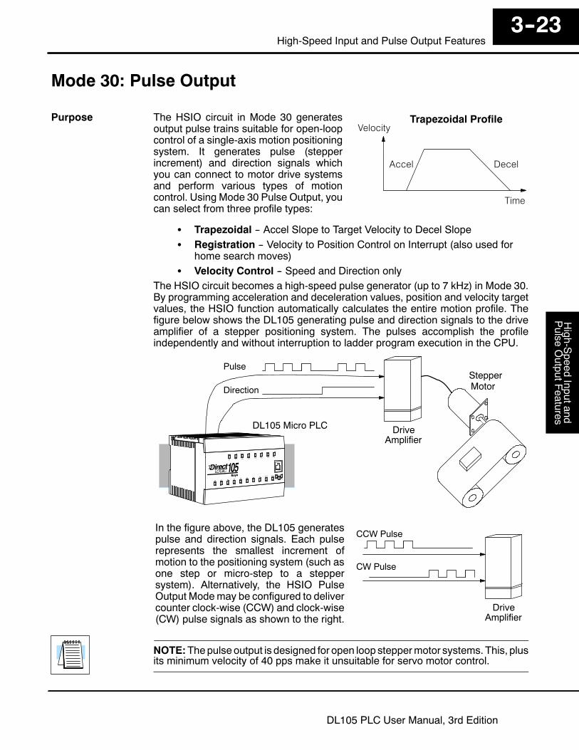
Mode 30: Pulse Output
The HSIO circuit in Mode 30 generatesoutput pulse trains suitable for open-loopcontrol of a single-axis motion positioningsystem. It generates pulse (stepperincrement) and direction signals whichyou can connect to motor drive systemsand perform various types of motioncontrol. Using Mode 30 Pulse Output, youcan select from three profile types:
Trapezoidal Profile
Time
Accel Decel
Velocity
S Trapezoidal -- Accel Slope to Target Velocity to Decel SlopeS Registration -- Velocity to Position Control on Interrupt (also used for
home search moves)S Velocity Control -- Speed and Direction only
The HSIO circuit becomes a high-speed pulse generator (up to 7 kHz) in Mode 30.By programming acceleration and deceleration values, position and velocity targetvalues, the HSIO function automatically calculates the entire motion profile. Thefigure below shows the DL105 generating pulse and direction signals to the driveamplifier of a stepper positioning system. The pulses accomplish the profileindependently and without interruption to ladder program execution in the CPU.
DriveAmplifier
StepperMotor
Pulse
Direction
DL105 Micro PLC
In the figure above, the DL105 generatespulse and direction signals. Each pulserepresents the smallest increment ofmotion to the positioning system (such asone step or micro-step to a steppersystem). Alternatively, the HSIO PulseOutput Modemay be configured to delivercounter clock-wise (CCW) and clock-wise(CW) pulse signals as shown to the right.
CCW Pulse
CW Pulse
DriveAmplifier
NOTE:Thepulse output is designed for open loop steppermotor systems. This, plusits minimum velocity of 40 pps make it unsuitable for servo motor control.
Purpose

High-Speed
Inputand
Pulse
OutputFeatures
3--24High-speed Input and Pulse Output Features
DL105 PLC User Manual, 3rd Edition
The diagram below shows HSIO functionality in Mode 30. When the lower byte ofHSIO Mode register V7633 contains a BCD “30”, the pulse output capability in theHSIO circuit is enabled. The pulse outputs use Y0 and Y1 terminals on the outputconnector. Remember that the outputs can only be DC type to operate.
Output Circuit
Input Circuit
CPU
PLCDL105
X0
Y0
X4-- X11
Y2 -- Y7
V-memory
V7633 xx30Mode Select
Y1 Preload Position Value
PULSE GEN.
X2 X1, X3
Interrupt
Y1
X0 Profile Complete
Y0 Start Profile
not used
HSIO
X1, X3 Filtered Inputs
(Pulse / CW) (Direction / CCW)
FILTER
IMPORTANT NOTE: In Pulse Output Mode, X0, Y0, and Y1 references areredefined or are used differently in two ways. Physical references refer to terminalscrews, while logical references refer to I/O references in the ladder program.Please read the items below to understand this very crucial point.
Notice the I/O point assignment and usage in the above diagram:S Physical input X0 is not used, so the terminal screw will not be wired.
However, the HSIO function uses logical reference X0 for “ProfileComplete” contact, which is available for ladder program use.
S X1 and X3 can only be filtered inputs in Pulse Output Mode, and theyare available as input contacts to the ladder program.
S X2 behaves as an external interrupt to the pulse generator forregistration profiles. In other profile modes, it can be used as a filteredinput just like X1 and X3 (registration mode configuration shown above).
S References “Y0” and “Y1” are used in two different ways. At the outputconnector, Y0 and Y1 terminals deliver the pulses to the motion system.The ladder program uses logical references Y0 and Y1 to initiate “StartProfile” and “Load Position Value” HSIO functions in Mode 30.
Hopefully, the above discussion will explain why some I/O reference names havedual meanings in Pulse Output Mode. Please read the remainder of this sectionwith care, to avoid confusion about which actual I/O function is being discussed.
Functional BlockDiagram
High-S
peedInputand
Pulse
OutputF
eatures3--25
High-Speed Input and Pulse Output Features
DL105 PLC User Manual, 3rd Edition
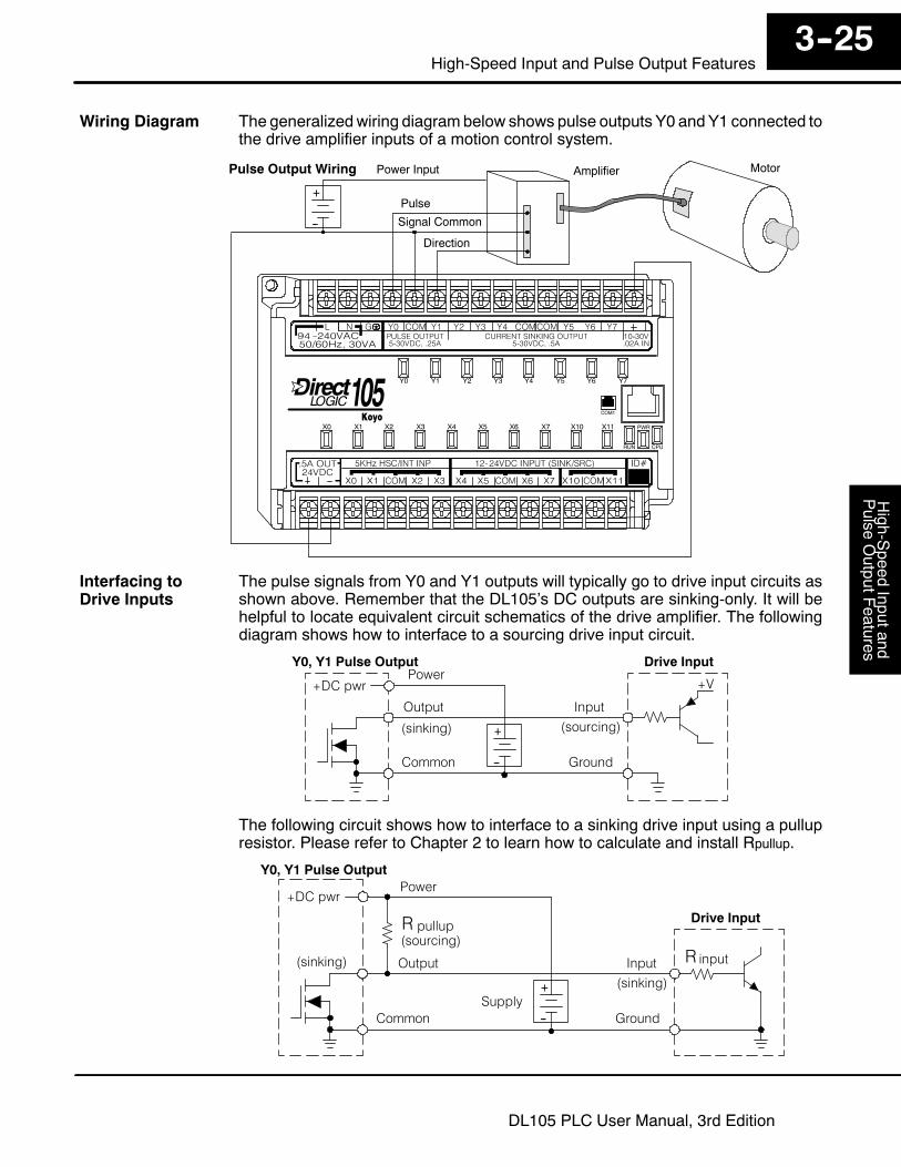
The generalizedwiring diagrambelow shows pulse outputs Y0 andY1 connected tothe drive amplifier inputs of a motion control system.
Signal Common
MotorAmplifierPulse Output Wiring
Pulse
Direction
Power Input
+
--
The pulse signals from Y0 and Y1 outputs will typically go to drive input circuits asshown above. Remember that the DL105’s DC outputs are sinking-only. It will behelpful to locate equivalent circuit schematics of the drive amplifier. The followingdiagram shows how to interface to a sourcing drive input circuit.
Drive Input
Output
Ground
Input
Common
+V
Y0, Y1 Pulse Output
+DC pwr
+
--
(sourcing)(sinking)
Power
The following circuit shows how to interface to a sinking drive input using a pullupresistor. Please refer to Chapter 2 to learn how to calculate and install Rpullup.
Drive Input
Output
Ground
Input
Common
Y0, Y1 Pulse Output
+DC pwr
+
--
(sourcing)
(sinking)
Power
(sinking)
pullup
Supply
R
inputR
Wiring Diagram
Interfacing toDrive Inputs
High-Speed
Inputand
Pulse
OutputFeatures
3--26High-speed Input and Pulse Output Features
DL105 PLC User Manual, 3rd Edition
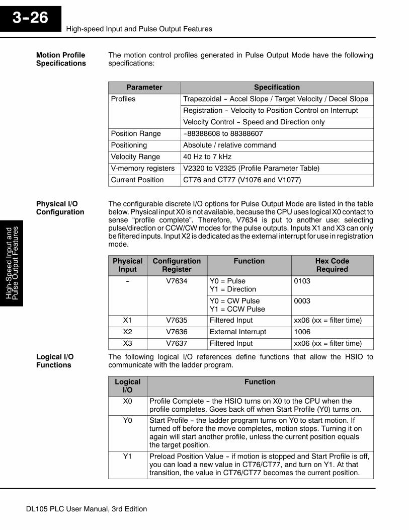
The motion control profiles generated in Pulse Output Mode have the followingspecifications:
Parameter Specification
Profiles Trapezoidal -- Accel Slope / Target Velocity / Decel Slope
Registration -- Velocity to Position Control on Interrupt
Velocity Control -- Speed and Direction only
Position Range --88388608 to 88388607
Positioning Absolute / relative command
Velocity Range 40 Hz to 7 kHz
V-memory registers V2320 to V2325 (Profile Parameter Table)
Current Position CT76 and CT77 (V1076 and V1077)
The configurable discrete I/O options for Pulse Output Mode are listed in the tablebelow.Physical inputX0 is not available, because theCPUuses logical X0 contact tosense “profile complete”. Therefore, V7634 is put to another use: selectingpulse/direction or CCW/CWmodes for the pulse outputs. Inputs X1 and X3 can onlybe filtered inputs. InputX2 is dedicatedas theexternal interrupt for use in registrationmode.
PhysicalInput
ConfigurationRegister
Function Hex CodeRequired
-- V7634 Y0 = PulseY1 = Direction
0103
Y0 = CW PulseY1 = CCW Pulse
0003
X1 V7635 Filtered Input xx06 (xx = filter time)
X2 V7636 External Interrupt 1006
X3 V7637 Filtered Input xx06 (xx = filter time)
The following logical I/O references define functions that allow the HSIO tocommunicate with the ladder program.
LogicalI/O
Function
X0 Profile Complete -- the HSIO turns on X0 to the CPU when theprofile completes. Goes back off when Start Profile (Y0) turns on.
Y0 Start Profile -- the ladder program turns on Y0 to start motion. Ifturned off before the move completes, motion stops. Turning it onagain will start another profile, unless the current position equalsthe target position.
Y1 Preload Position Value -- if motion is stopped and Start Profile is off,you can load a new value in CT76/CT77, and turn on Y1. At thattransition, the value in CT76/CT77 becomes the current position.
Motion ProfileSpecifications
Physical I/OConfiguration
Logical I/OFunctions
High-S
peedInputand
Pulse
OutputF
eatures3--27
High-Speed Input and Pulse Output Features
DL105 PLC User Manual, 3rd Edition
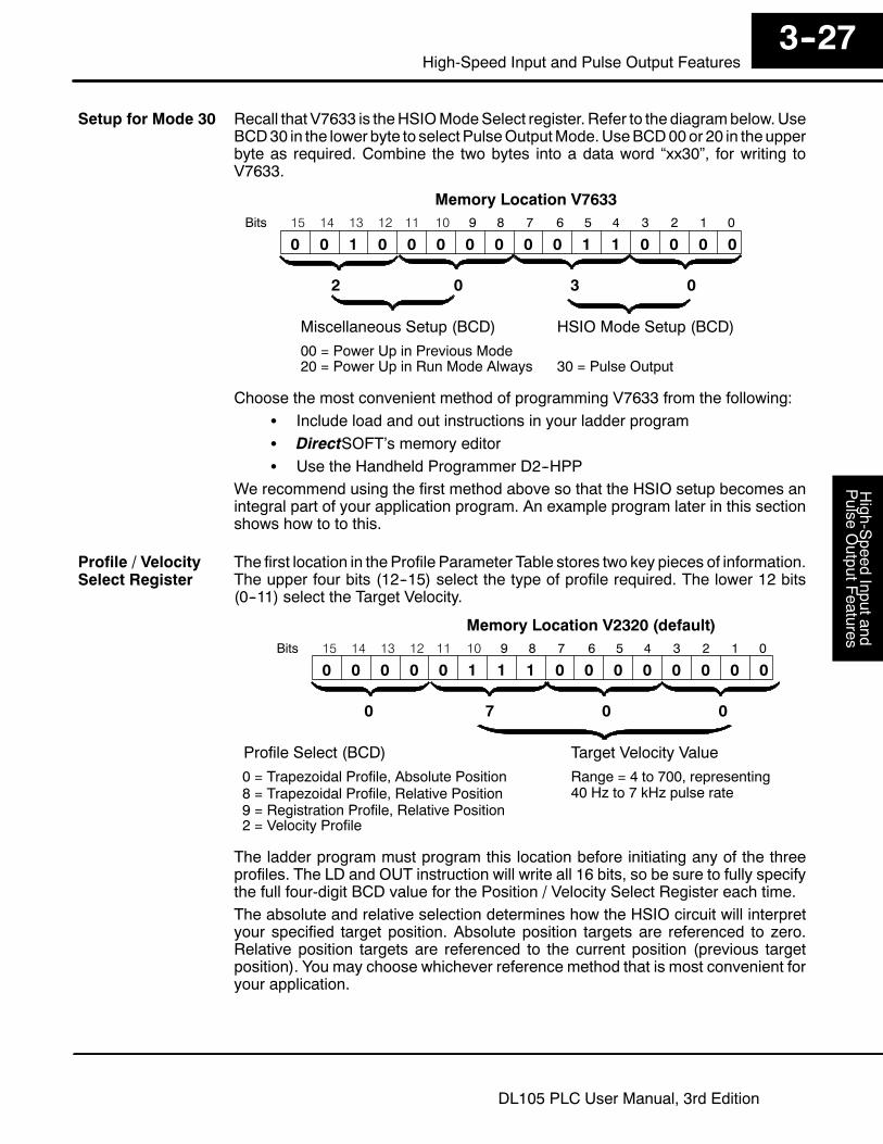
Recall that V7633 is theHSIOModeSelect register. Refer to the diagrambelow.UseBCD30 in the lower byte to select PulseOutputMode.UseBCD00or 20 in theupperbyte as required. Combine the two bytes into a data word “xx30”, for writing toV7633.
015 14 13 12
Memory Location V763311 10 123456789Bits
001 00011000
HSIO Mode Setup (BCD)Miscellaneous Setup (BCD)
0 0 0 0
00 = Power Up in Previous Mode20 = Power Up in Run Mode Always 30 = Pulse Output
2 0 03
0
Choose the most convenient method of programming V7633 from the following:S Include load and out instructions in your ladder programS DirectSOFT’s memory editorS Use the Handheld Programmer D2--HPP
We recommend using the first method above so that the HSIO setup becomes anintegral part of your application program. An example program later in this sectionshows how to to this.
The first location in the Profile Parameter Table stores two key pieces of information.The upper four bits (12--15) select the type of profile required. The lower 12 bits(0--11) select the Target Velocity.
015 14 13 12
Memory Location V2320 (default)11 10 123456789Bits
000 00000000
Target Velocity ValueProfile Select (BCD)
0 1 1 1
0 = Trapezoidal Profile, Absolute Position8 = Trapezoidal Profile, Relative Position
Range = 4 to 700, representing40 Hz to 7 kHz pulse rate
0 7 00
0
9 = Registration Profile, Relative Position2 = Velocity Profile
The ladder program must program this location before initiating any of the threeprofiles. The LD and OUT instruction will write all 16 bits, so be sure to fully specifythe full four-digit BCD value for the Position / Velocity Select Register each time.The absolute and relative selection determines how the HSIO circuit will interpretyour specified target position. Absolute position targets are referenced to zero.Relative position targets are referenced to the current position (previous targetposition). You may choose whichever reference method that is most convenient foryour application.
Setup for Mode 30
Profile / VelocitySelect Register
High-Speed
Inputand
Pulse
OutputFeatures
3--28High-speed Input and Pulse Output Features
DL105 PLC User Manual, 3rd Edition
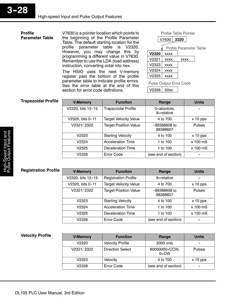
V7630 is a pointer location which points tothe beginning of the Profile ParameterTable. The default starting location for theprofile parameter table is V2320.However, you may change this byprogramming a different value in V7630.Remember to use the LDA (load address)instruction, converting octal into hex.The HSIO uses the next V-memoryregister past the bottom of the profileparameter table to indicate profile errors.See the error table at the end of thissection for error code definitions.
Profile Parameter TableV2320 xxxxV2321 xxxxV2323 xxxxV2324 xxxx
xxxx
V7630 2320
Profile Table Pointer
V2325 xxxx
V2326 00xx
Pulse Output Error Code
V-Memory Function Range Units
V2320, bits 12--15 Trapezoidal Profile 0=absolute,8=relative
--
V2320, bits 0--11 Target Velocity Value 4 to 700 x 10 pps
V2321/ 2322 Target Position Value --88388608 to88388607
Pulses
V2323 Starting Velocity 4 to 100 x 10 pps
V2324 Acceleration Time 1 to 100 x 100 mS
V2325 Deceleration Time 1 to 100 x 100 mS
V2326 Error Code (see end of section) --
V-Memory Function Range Units
V2320, bits 12--15 Registration Profile 9=relative --
V2320, bits 0--11 Target Velocity Value 4 to 700 x 10 pps
V2321/ 2322 Target Position Value --88388608 to88388607
Pulses
V2323 Starting Velocity 4 to 100 x 10 pps
V2324 Acceleration Time 1 to 100 x 100 mS
V2325 Deceleration Time 1 to 100 x 100 mS
V2326 Error Code (see end of section) --
V-Memory Function Range Units
V2320 Velocity Profile 2000 only --
V2321/ 2322 Direction Select 80000000=CCW,0=CW
Pulses
V2323 Velocity 4 to 700 x 10 pps
V2326 Error Code (see end of section) --
ProfileParameter Table
Trapezoidal Profile
Registration Profile
Velocity Profile
High-S
peedInputand
Pulse
OutputF
eatures3--29
High-Speed Input and Pulse Output Features
DL105 PLC User Manual, 3rd Edition
Pulse Output Mode generates three types of motion profiles. Most applications useone type for most moves. However, each move can be different if required.
S Trapezoidal -- Accel Slope to Target Velocity to Decel SlopeS Registration -- Velocity to Position Control on InterruptS Velocity Control -- Speed and Direction only
The trapezoidal profile is the mostcommon positioning profile. It moves theload to a pre-defined target position bycreating a move profile. The accelerationslope is applied at the starting position.The deceleration slope is appliedbackwards from the target position. Theremainder of the move in the middle isspent traveling at a defined velocity.
Trapezoidal Profile
Time
Accel Decel
Velocity
Start position Target position
Fixed Velocity
Trapezoidal profiles are best for simple point-to-point moves, when the distancebetween the starting and ending positions of the move is known in advance.
Registration profiles solve a class ofmotion control problems. In someapplications, product material in workmoves past a work tool such as a drillstation. Shown to the right, registrationmarks on the scrap area of the work-pieceallow amachine tool to register its positionrelative to the rectangle, to drill properly.Home search moves allow open-loopmotion systems to re-calibrate (preload)the current position value at powerup.Registration profiles are a combination ofvelocity and position control modes. Themove begins by accelerating to aprogrammed velocity. The velocity issustained and the move is of indefiniteduration. When an external interruptsignal occurs (due to registrationsensing), the profile switches fromvelocityto position control. The move ends bycontinuing motion a pre-defined distancepast the interrupt point (such as a drill holelocation). The deceleration ramp isapplied in advance of the target position.
Registration Profile
Accel Decel
Velocity
Interrupt
VelocityControl
PositionControl
Registration marks
Finished part areaScrapArea
Target position
direction of motion
The velocity profile controls only thedirection and speed of motion. There is notarget position specified, so the move canbe of indefinite length. Only the firstvelocity value needs to be defined. Theremaining velocity values can be createdwhile motion in in progress. Arrows in theprofile shown indicate velocity changes.
Velocity Profile
Time
Velocity
Choosing theProfile Type
TrapezoidalProfile Defined
Registration andHome SearchProfiles Defined
Velocity ProfileDefined

High-Speed
Inputand
Pulse
OutputFeatures
3--30High-speed Input and Pulse Output Features
DL105 PLC User Manual, 3rd Edition
Trapezoidal Profile Operation
The trapezoidal profile is best suited for simple point-to-pointmoves,when the targetposition is known in advance. Starting velocities must be within the rage of 40 pps to1 kpps. The remainder of the profile parameters are in the profile parameter table.
Trapezoidal Profile
Time
Accel Decel
Velocity
Start position Target position
Target Velocity
StartingVelocity
Start
ProfileComplete
Y0
X0
The time line of signal traces below the profile indicates the order of events.The HSIO uses logical output Y0 as the Start input to the HSIO, which starts theprofile. Immediately the HSIO turns off the Profile Complete signal (logical X0), sothe ladder program can monitor the progress of the move. Typically a ladderprogram will monitor this bit so it knows when to initiate the next profile move.If you are familiar with motion control, you’ll notice that we do not have to specify thedirection of themove. The HSIO function examines the target position relative to thecurrent position, and automatically outputs the correct direction information to themotor drive.Notice that themotion accelerates immediately to the starting velocity. This segmentis useful in stepper systems so we can jump past low speed areas when low-torqueproblems or a resonant point in themotormight cause a stall. (Whena steppermotorstalls, we have lost the position of the load in open-loop positioning systems).However, is is preferable not to make the starting velocity too large, because thestepper motor will also “slip” some pulses due to the inertia of the system.When you need to change the current position value, use logical Y1 output coil toload a new value into the HSIO counter. If the ladder program loads a new value inCT76/CT77 (V1076/V1077), then energizing Y1 will copy that value into the HSIOcircuit counter. Thismust occur before the profile begins, because the HSIO ignoresY1 during motion.
Trapezoidal ProfileApplications
High-S
peedInputand
Pulse
OutputF
eatures3--31
High-Speed Input and Pulse Output Features
DL105 PLC User Manual, 3rd Edition
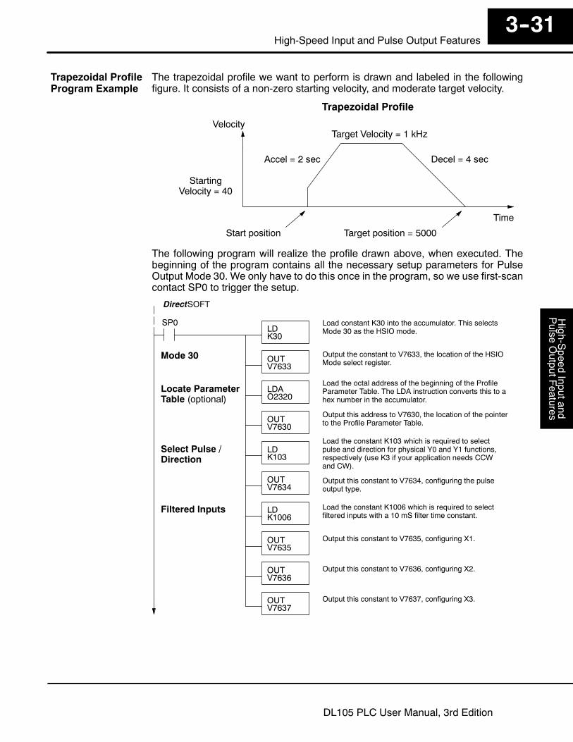
The trapezoidal profile we want to perform is drawn and labeled in the followingfigure. It consists of a non-zero starting velocity, and moderate target velocity.
Trapezoidal Profile
Time
Accel = 2 sec Decel = 4 sec
Velocity
Start position Target position = 5000
Target Velocity = 1 kHz
StartingVelocity = 40
The following program will realize the profile drawn above, when executed. Thebeginning of the program contains all the necessary setup parameters for PulseOutput Mode 30. We only have to do this once in the program, so we use first-scancontact SP0 to trigger the setup.
SP0LDK30
Load constant K30 into the accumulator. This selectsMode 30 as the HSIO mode.
OUTV7633
Output the constant to V7633, the location of the HSIOMode select register.
LDAO2320
Load the octal address of the beginning of the ProfileParameter Table. The LDA instruction converts this to ahex number in the accumulator.
OUTV7630
Output this address to V7630, the location of the pointerto the Profile Parameter Table.
DirectSOFT
Mode 30
LDK1006
Load the constant K1006 which is required to selectfiltered inputs with a 10 mS filter time constant.
OUTV7635
Output this constant to V7635, configuring X1.
Filtered Inputs
OUTV7636
Output this constant to V7636, configuring X2.
OUTV7637
Output this constant to V7637, configuring X3.
LDK103
Load the constant K103 which is required to selectpulse and direction for physical Y0 and Y1 functions,respectively (use K3 if your application needs CCWand CW).
OUTV7634
Output this constant to V7634, configuring the pulseoutput type.
Select Pulse /Direction
Locate ParameterTable (optional)
Trapezoidal ProfileProgram Example
High-Speed
Inputand
Pulse
OutputFeatures
3--32High-speed Input and Pulse Output Features
DL105 PLC User Manual, 3rd Edition
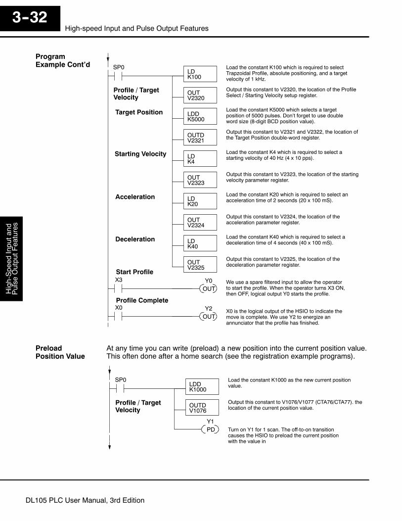
Profile / TargetVelocity
LDK100
Load the constant K100 which is required to selectTrapzoidal Profile, absolute positioning, and a targetvelocity of 1 kHz.
OUTV2320
Output this constant to V2320, the location of the ProfileSelect / Starting Velocity setup register.
Target Position
SP0
LDDK5000
Load the constant K5000 which selects a targetposition of 5000 pulses. Don’t forget to use doubleword size (8-digit BCD position value).
OUTDV2321
Output this constant to V2321 and V2322, the location ofthe Target Position double-word register.
OUTV2323
Output this constant to V2323, the location of the startingvelocity parameter register.
LDK4
Load the constant K4 which is required to select astarting velocity of 40 Hz (4 x 10 pps).
Starting Velocity
OUTV2324
Output this constant to V2324, the location of theacceleration parameter register.
LDK20
Load the constant K20 which is required to select anacceleration time of 2 seconds (20 x 100 mS).Acceleration
OUTV2325
Output this constant to V2325, the location of thedeceleration parameter register.
LDK40
Load the constant K40 which is required to select adeceleration time of 4 seconds (40 x 100 mS).Deceleration
X3
OUTWe use a spare filtered input to allow the operatorto start the profile. When the operator turns X3 ON,then OFF, logical output Y0 starts the profile.
Y0Start Profile
X0
OUTX0 is the logical output of the HSIO to indicate themove is complete. We use Y2 to energize anannunciator that the profile has finished.
Y2Profile Complete
At any time you can write (preload) a new position into the current position value.This often done after a home search (see the registration example programs).
Profile / TargetVelocity
LDDK1000
Load the constant K1000 as the new current positionvalue.
OUTDV1076
Output this constant to V1076/V1077 (CTA76/CTA77). thelocation of the current position value.
SP0
PD Turn on Y1 for 1 scan. The off-to-on transitioncauses the HSIO to preload the current positionwith the value in
Y1
ProgramExample Cont’d
PreloadPosition Value
High-S
peedInputand
Pulse
OutputF
eatures3--33
High-Speed Input and Pulse Output Features
DL105 PLC User Manual, 3rd Edition
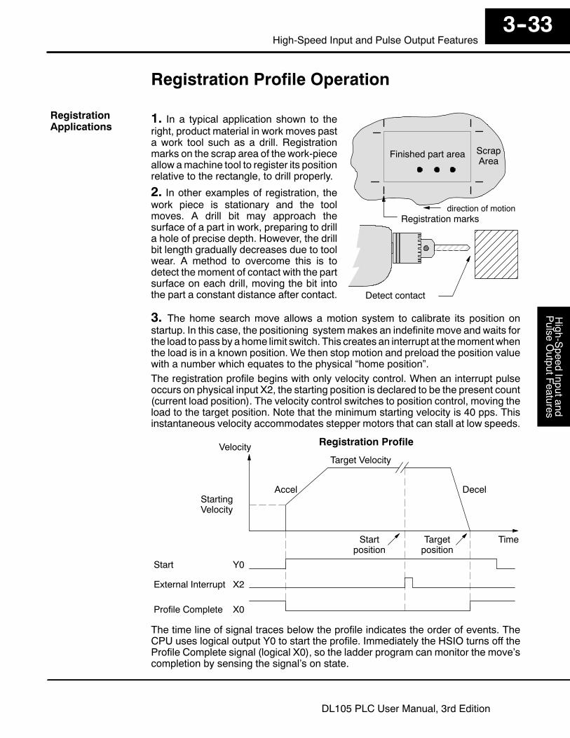
Registration Profile Operation
1. In a typical application shown to theright, product material in work moves pasta work tool such as a drill. Registrationmarks on the scrap area of the work-pieceallow amachine tool to register its positionrelative to the rectangle, to drill properly.
2. In other examples of registration, thework piece is stationary and the toolmoves. A drill bit may approach thesurface of a part in work, preparing to drilla hole of precise depth. However, the drillbit length gradually decreases due to toolwear. A method to overcome this is todetect the moment of contact with the partsurface on each drill, moving the bit intothe part a constant distance after contact. Detect contact
Finished part area ScrapArea
Registration marksdirection of motion
3. The home search move allows a motion system to calibrate its position onstartup. In this case, the positioning systemmakes an indefinite move and waits forthe load to pass by a home limit switch. This creates an interrupt at themomentwhenthe load is in a known position. We then stop motion and preload the position valuewith a number which equates to the physical “home position”.The registration profile begins with only velocity control. When an interrupt pulseoccurs on physical input X2, the starting position is declared to be the present count(current load position). The velocity control switches to position control, moving theload to the target position. Note that the minimum starting velocity is 40 pps. Thisinstantaneous velocity accommodates stepper motors that can stall at low speeds.
Registration Profile
Time
Accel Decel
Velocity
Startposition
Targetposition
Target Velocity
StartingVelocity
Start
External Interrupt
Y0
X2
Profile Complete X0
The time line of signal traces below the profile indicates the order of events. TheCPU uses logical output Y0 to start the profile. Immediately the HSIO turns off theProfile Complete signal (logical X0), so the ladder program can monitor the move’scompletion by sensing the signal’s on state.
RegistrationApplications
High-Speed
Inputand
Pulse
OutputFeatures
3--34High-speed Input and Pulse Output Features
DL105 PLC User Manual, 3rd Edition
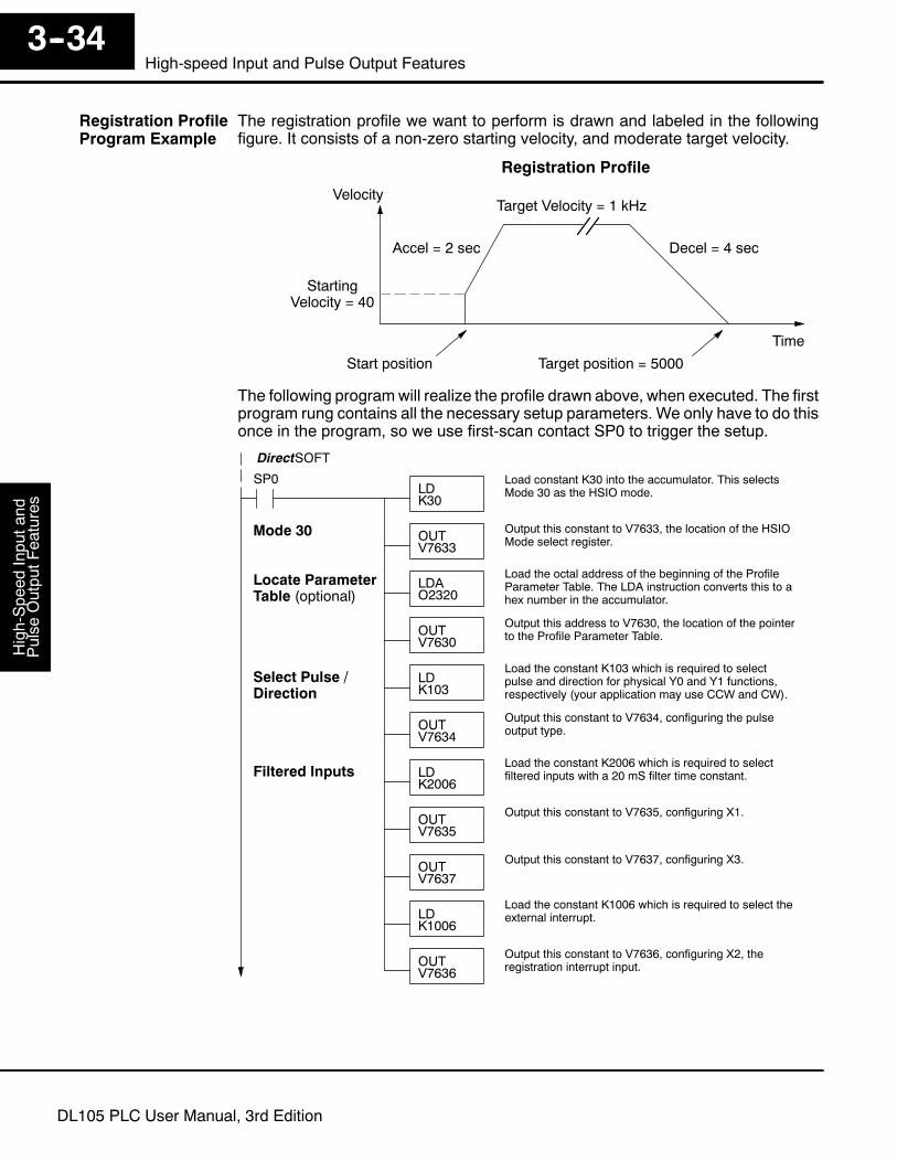
The registration profile we want to perform is drawn and labeled in the followingfigure. It consists of a non-zero starting velocity, and moderate target velocity.
Registration Profile
Time
Accel = 2 sec Decel = 4 sec
Velocity
Start position Target position = 5000
Target Velocity = 1 kHz
StartingVelocity = 40
The following programwill realize the profile drawn above, when executed. The firstprogram rung contains all the necessary setup parameters. We only have to do thisonce in the program, so we use first-scan contact SP0 to trigger the setup.
SP0LDK30
Load constant K30 into the accumulator. This selectsMode 30 as the HSIO mode.
OUTV7633
Output this constant to V7633, the location of the HSIOMode select register.
LDAO2320
Load the octal address of the beginning of the ProfileParameter Table. The LDA instruction converts this to ahex number in the accumulator.
OUTV7630
Output this address to V7630, the location of the pointerto the Profile Parameter Table.
DirectSOFT
Mode 30
LDK2006
Load the constant K2006 which is required to selectfiltered inputs with a 20 mS filter time constant.Filtered Inputs
OUTV7635
Output this constant to V7635, configuring X1.
OUTV7637
Output this constant to V7637, configuring X3.
LDK103
Load the constant K103 which is required to selectpulse and direction for physical Y0 and Y1 functions,respectively (your application may use CCW and CW).
OUTV7634
Output this constant to V7634, configuring the pulseoutput type.
Select Pulse /Direction
LDK1006
Load the constant K1006 which is required to select theexternal interrupt.
OUTV7636
Output this constant to V7636, configuring X2, theregistration interrupt input.
Locate ParameterTable (optional)
Registration ProfileProgram Example

High-S
peedInputand
Pulse
OutputF
eatures3--35
High-Speed Input and Pulse Output Features
DL105 PLC User Manual, 3rd Edition
Start Profile
Profile / TargetVelocity
LDK9100
Load the constant K9100 which is required to selectRegistration Profile, relative positioning, and a targetvelocity of 1 kHz (9xxx times 10 pps).
OUTV2320
Output this constant to V2320, the location of the ProfileSelect / Starting Velocity setup register.
Target Position
SP0
LDDK5000
Load the constant K5000 which selects a targetposition of 5000 pulses. Don’t forget to use doubleword size (8-digit BCD position value).
OUTDV2321
Output this constant to V2321 and V2322, the location ofthe Target Position double-word register.
OUTV2323
Output this constant to V2323, the location of the startingvelocity parameter register.
LDK4
Load the constant K4 which is required to select astarting velocity of 40 Hz (4 x 10 pps).
Starting Velocity
OUTV2324
Output this constant to V2324, the location of theacceleration parameter register.
LDK20
Load the constant K20 which is required to select anacceleration time of 2 seconds (20 x 100 mS).Acceleration
OUTV2325
Output this constant to V2325, the location of thedeceleration parameter register.
LDK40
Load the constant K40 which is required to select adeceleration time of 4 seconds (40 x 100 mS).Deceleration
X3
SET We use a spare filtered input to allow the operatorto start the profile. X3 is a momentary Start switch.When the operator turns X3 ON, logical output Y0starts the profile.
Y0
X0
OUT X0 is the logical output of the HSIO to indicate themove is complete. We use Y2 to energize anannunciator that the profile has finished. This won’toccur until after the interrupt from X2 has occurredand the profile is complete.
Y2
Profile Complete
PDC0
C0
RSTY0
The profile will begin when the start input (X3) is given. Then the motion begins anindefinitemove, which lasts until an external interrupt onX2 occurs. Then themotioncontinues on for 5000 more pulses before stopping.
ProgramExample Cont’d

High-Speed
Inputand
Pulse
OutputFeatures
3--36High-speed Input and Pulse Output Features
DL105 PLC User Manual, 3rd Edition
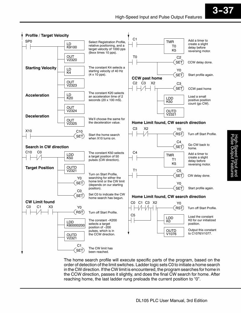
One of themore challenging aspects of motion control is the establishment of actualposition at powerup. This is especially true for open-loop systemswhich do not havea position feedback device. However, a simple limit switch located at an exactlocation on the positioningmechanism can provide “position feedback” at one point.For most stepper control systems, this method is a good and economical solution.
MotionNumbering System
Motor
Load
CCW limit (X1) CW limit (X3)Home limit (X2)
0 1000 2000 3000--1000--2000--3000
Limit Switches
Positioning System
In the drawing above, the load moves left or right depending on the CCW/CWdirection of motor rotation. The PLC ladder program senses the CCW and CW limitswitches to stop the motor, before the load moves out-of-bounds and damages themachine. The home limit switch is used at powerup to establish the actual position.The numbering system is arbitrary, depending on a machine’s engineering units.At powerup, we do not knowwhether the load is located to the left or to the right of thehome limit switch. Therefore, we will initiate a home search profile, using theregistration mode. The home limit switch is wired to X2, causing the interrupt. Wechoose an arbitrary initial search direction, moving in the CW (left-to-right) direction.
S If the home limit switch closes first, then we stop and initialize theposition (this value is typically “0”, but it may be different if preferred).
S However, if the CW limit switch closes first, we must reverse the motorand move until the home limit switch closes, stopping just past it.
In the latter case, we repeat the first move, because we always need to make thefinal approach to the home limit switch from the same direction, so that the finalphysical position is the same in either case!
SP0LDK30
Selects Mode 30 asthe HSIO mode.
OUTV7633
LDAO2320
OUTV7630
Configure the addressof the parameter table.
DirectSOFT
Mode 30
LDK103
Configure the Y0 and Y1pulse outputs for pulseand direction, respectively.
OUTV7634
Select Pulse /Direction
LocateParameterTable (optional)
LDK2006
The constant K2006selects a 20 mS filtertime constant.
OUTV7635
Output this constant toV7635, configuring X1.
OUTV7637
Output this constant toV7637, configuring X3.
LDK1006
The constant K1006selects a 10 mS filtertime constant.
OUTV7636
Output this constant toV7636, configuring X2, theregistration interrupt input.
Filtered Inputs
Home SearchProgram Example
High-S
peedInputand
Pulse
OutputF
eatures3--37
High-Speed Input and Pulse Output Features
DL105 PLC User Manual, 3rd Edition
Profile / Target Velocity
LDK9100
Select Registration Profile,relative positioning, and atarget velocity of 1000 pps(9xxx times 10 pps).
OUTV2320
Target Position
SP0
LDDK50
The constant K50 selectsa target position of 50pulses (CW direction).
OUTDV2321
OUTV2323
LDK4
The constant K4 selects astarting velocity of 40 Hz(4 x 10 pps).
Starting Velocity
OUTV2324
LDK20
The constant K20 selectsan acceleration time of 2seconds (20 x 100 mS).
Acceleration
OUTV2325
We’ll choose the same forthe deceleration value.
Deceleration
C10
SET
Turn on Start Profile,searching for either thehome limit or the CW limit(depends on our startingposition).
Y0
Search in CW direction
C0
RSTY0
LDDK80000200
The constant --K200selects a targetposition of --200pulses, which is inthe CCW direction.OUTD
V2321
CW Limit found
C3 X2
RSTY0
LDDK0
Load the constantK0 for our initializedposition.
OUTDV1076
Output this constantto C1076/V1077.
SETGo CW back tohome.
C4
Home Limit found, CW search direction
Turn off Start Profile.
SETThe CW limit hasbeen reached.
C1
C0
RSTY0
Home Limit found, CW search direction
Turn off Start Profile.Turn off Start Profile.
SETC0
Set C0 to indicate the CWhome search has begun.
C0
C1 X3
X10
SETC10
Start the home searchwhen X10 turns on.
C1TMR
K5
Add a timer tocreate a slightdelay beforereversing motor.
T0
T0
SETC2
CCW delay done.
SET Start profile again.Y0
C2
SETC3
LDDK50
Load a smallpositive positioncount (go CW).
OUTDV2321
CCW past home
CCW past home
C3 X2
C4TMR
K5
Add a timer tocreate a slightdelay beforereversing motor.
T1
T1
SETC5
CW delay done.
SET Start profile again.Y0
C1 C3 X2
C5
The home search profile will execute specific parts of the program, based on theorder of detection of the limit switches. Ladder logic sets C0 to initiate a home searchin theCWdirection. If theCW limit is encountered, the programsearches for home inthe CCW direction, passes it slightly, and does the final CW search for home. Afterreaching home, the last ladder rung preloads the current position to “0”.
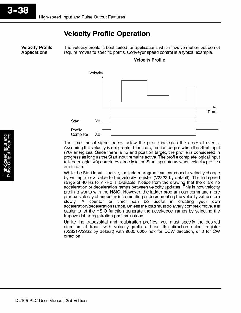
High-Speed
Inputand
Pulse
OutputFeatures
3--38High-speed Input and Pulse Output Features
DL105 PLC User Manual, 3rd Edition
Velocity Profile Operation
The velocity profile is best suited for applications which involve motion but do notrequire moves to specific points. Conveyor speed control is a typical example.
Velocity Profile
Time
Velocity
Start
ProfileComplete
Y0
X0
The time line of signal traces below the profile indicates the order of events.Assuming the velocity is set greater than zero, motion begins when the Start input(Y0) energizes. Since there is no end position target, the profile is considered inprogress as long as the Start input remains active. The profile complete logical inputto ladder logic (X0) correlates directly to the Start input status when velocity profilesare in use.While the Start input is active, the ladder program can command a velocity changeby writing a new value to the velocity register (V2323 by default). The full speedrange of 40 Hz to 7 kHz is available. Notice from the drawing that there are noacceleration or deceleration ramps between velocity updates. This is how velocityprofiling works with the HSIO. However, the ladder program can command moregradual velocity changes by incrementing or decrementing the velocity value moreslowly. A counter or timer can be useful in creating your ownacceleration/deceleration ramps. Unless the loadmust do a very complexmove, it iseasier to let the HSIO function generate the accel/decel ramps by selecting thetrapezoidal or registration profiles instead.Unlike the trapezoidal and registration profiles, you must specify the desireddirection of travel with velocity profiles. Load the direction select register(V2321/V2322 by default) with 8000 0000 hex for CCW direction, or 0 for CWdirection.
Velocity ProfileApplications
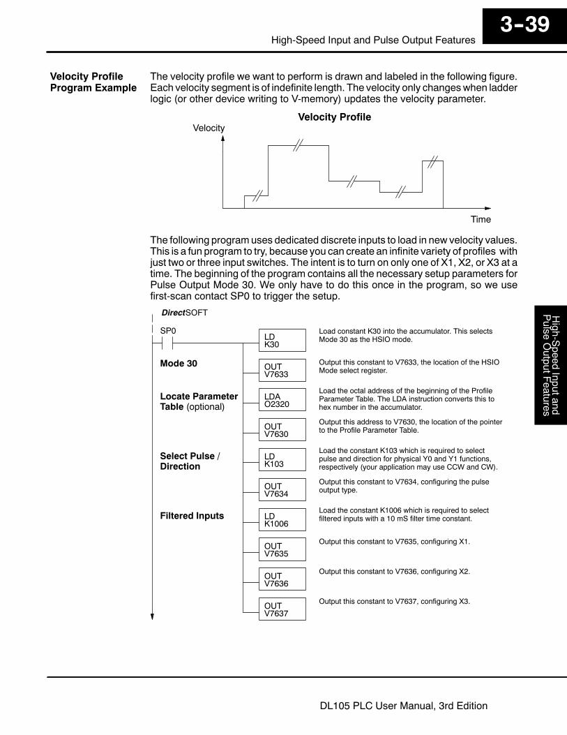
High-S
peedInputand
Pulse
OutputF
eatures3--39
High-Speed Input and Pulse Output Features
DL105 PLC User Manual, 3rd Edition
The velocity profile we want to perform is drawn and labeled in the following figure.Each velocity segment is of indefinite length. The velocity only changeswhen ladderlogic (or other device writing to V-memory) updates the velocity parameter.
Velocity Profile
Time
Velocity
The following programuses dedicated discrete inputs to load in new velocity values.This is a fun program to try, because you can create an infinite variety of profiles withjust two or three input switches. The intent is to turn on only one of X1, X2, or X3 at atime. The beginning of the program contains all the necessary setup parameters forPulse Output Mode 30. We only have to do this once in the program, so we usefirst-scan contact SP0 to trigger the setup.
SP0LDK30
Load constant K30 into the accumulator. This selectsMode 30 as the HSIO mode.
OUTV7633
Output this constant to V7633, the location of the HSIOMode select register.
LDAO2320
Load the octal address of the beginning of the ProfileParameter Table. The LDA instruction converts this tohex number in the accumulator.
OUTV7630
Output this address to V7630, the location of the pointerto the Profile Parameter Table.
DirectSOFT
Mode 30
LDK1006
Load the constant K1006 which is required to selectfiltered inputs with a 10 mS filter time constant.
OUTV7635
Output this constant to V7635, configuring X1.
Filtered Inputs
OUTV7636
Output this constant to V7636, configuring X2.
OUTV7637
Output this constant to V7637, configuring X3.
LDK103
Load the constant K103 which is required to selectpulse and direction for physical Y0 and Y1 functions,respectively (your application may use CCW and CW).
OUTV7634
Output this constant to V7634, configuring the pulseoutput type.
Select Pulse /Direction
Locate ParameterTable (optional)
Velocity ProfileProgram Example

High-Speed
Inputand
Pulse
OutputFeatures
3--40High-speed Input and Pulse Output Features
DL105 PLC User Manual, 3rd Edition
Profile / TargetVelocity
LDK2000
Load the constant K2000 which is required to selectVelocity Profile. This data word contains no velocityinformation in the case of velocity mode.
OUTV2320
Output this constant to V2320, the location of the ProfileSelect setup register.
Select Direction
SP0
LDDK80000000
Load the constant K80000000 which selects CCWdirection for Velocity Profiles. Don’t forget to use doubleword size (8-digit BCD position value).
OUTDV2321
Output this constant to V2321 and V2322, the location ofthe Target Position double-word register.
OUTV2323
Output this constant to V2323, the location of the velocityparameter register. After the program is running, we canwrite here again, using discrete input switches.
LDK10
Load the constant K10 which is required to select aninitial velocity of 100 pps (uses x10 multiplier).
Set Velocity
X1
OUT We use a spare filtered input to allow the operatorto start the profile. When the operator turns X1 ONand leaves it on, logical output Y0 starts the profile.
Y0
Start Profile
LDK50
OUTV2323
X2
Output this constant to V2323, the location of the velocityparameter register. The speed will change immediately.
Load the constant K50 which is required to select avelocity of 500 pps when the operator closes X2.
Go Slow
LDK200
OUTV2323
X3
Output this constant to V2323, the location of the velocityparameter register. The speed will change immediately.
Load the constant K200 which is required to select avelocity of 2000 pps when the operator closes X3.
Go Moderately
LDK600
OUTV2323
X4
Output this constant to V2323, the location of the velocityparameter register. The speed will change immediately.
Load the constant K600 which is required to select avelocity of 6000 pps when the operator closes X4.
Go Fast
ProgramExample Cont’d
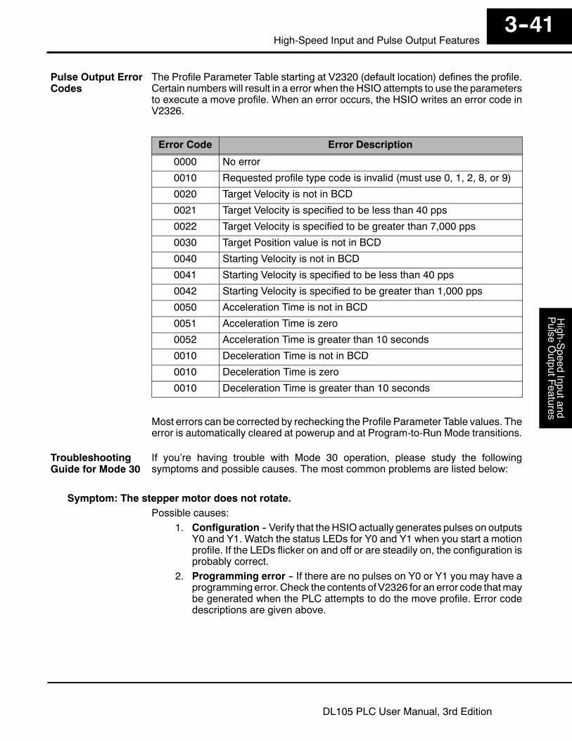
High-S
peedInputand
Pulse
OutputF
eatures3--41
High-Speed Input and Pulse Output Features
DL105 PLC User Manual, 3rd Edition
The Profile Parameter Table starting at V2320 (default location) defines the profile.Certain numbers will result in a error when the HSIO attempts to use the parametersto execute a move profile. When an error occurs, the HSIO writes an error code inV2326.
Error Code Error Description
0000 No error
0010 Requested profile type code is invalid (must use 0, 1, 2, 8, or 9)
0020 Target Velocity is not in BCD
0021 Target Velocity is specified to be less than 40 pps
0022 Target Velocity is specified to be greater than 7,000 pps
0030 Target Position value is not in BCD
0040 Starting Velocity is not in BCD
0041 Starting Velocity is specified to be less than 40 pps
0042 Starting Velocity is specified to be greater than 1,000 pps
0050 Acceleration Time is not in BCD
0051 Acceleration Time is zero
0052 Acceleration Time is greater than 10 seconds
0010 Deceleration Time is not in BCD
0010 Deceleration Time is zero
0010 Deceleration Time is greater than 10 seconds
Most errors can be corrected by rechecking the Profile Parameter Table values. Theerror is automatically cleared at powerup and at Program-to-Run Mode transitions.
If you’re having trouble with Mode 30 operation, please study the followingsymptoms and possible causes. The most common problems are listed below:
Symptom: The stepper motor does not rotate.Possible causes:
1. Configuration -- Verify that the HSIO actually generates pulses on outputsY0 and Y1. Watch the status LEDs for Y0 and Y1 when you start a motionprofile. If the LEDs flicker on and off or are steadily on, the configuration isprobably correct.
2. Programming error -- If there are no pulses on Y0 or Y1 you may have aprogramming error. Check the contents of V2326 for an error code thatmaybe generated when the PLC attempts to do the move profile. Error codedescriptions are given above.
Pulse Output ErrorCodes
TroubleshootingGuide for Mode 30
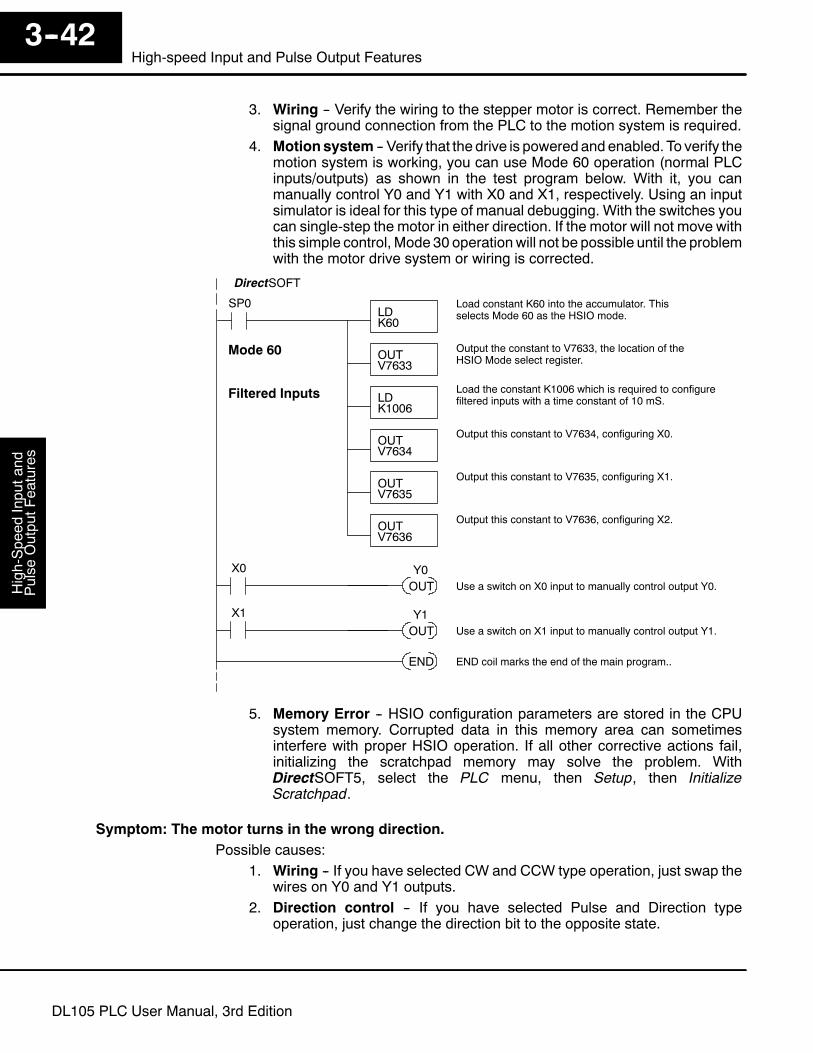
High-Speed
Inputand
Pulse
OutputFeatures
3--42High-speed Input and Pulse Output Features
DL105 PLC User Manual, 3rd Edition
3. Wiring -- Verify the wiring to the stepper motor is correct. Remember thesignal ground connection from the PLC to the motion system is required.
4. Motionsystem -- Verify that the drive is powered and enabled. To verify themotion system is working, you can use Mode 60 operation (normal PLCinputs/outputs) as shown in the test program below. With it, you canmanually control Y0 and Y1 with X0 and X1, respectively. Using an inputsimulator is ideal for this type of manual debugging. With the switches youcan single-step the motor in either direction. If the motor will not move withthis simple control, Mode 30 operationwill not be possible until the problemwith the motor drive system or wiring is corrected.
SP0LDK60
Load constant K60 into the accumulator. Thisselects Mode 60 as the HSIO mode.
OUTV7633
Output the constant to V7633, the location of theHSIO Mode select register.
DirectSOFT
Mode 60
OUTV7635
Output this constant to V7635, configuring X1.
Filtered Inputs
OUTV7636
Output this constant to V7636, configuring X2.
LDK1006
Load the constant K1006 which is required to configurefiltered inputs with a time constant of 10 mS.
OUTV7634
Output this constant to V7634, configuring X0.
END END coil marks the end of the main program..
X0
OUT Use a switch on X0 input to manually control output Y0.Y0
X1
OUT Use a switch on X1 input to manually control output Y1.Y1
5. Memory Error -- HSIO configuration parameters are stored in the CPUsystem memory. Corrupted data in this memory area can sometimesinterfere with proper HSIO operation. If all other corrective actions fail,initializing the scratchpad memory may solve the problem. WithDirectSOFT5, select the PLC menu, then Setup, then InitializeScratchpad.
Symptom: The motor turns in the wrong direction.Possible causes:
1. Wiring -- If you have selected CW and CCW type operation, just swap thewires on Y0 and Y1 outputs.
2. Direction control -- If you have selected Pulse and Direction typeoperation, just change the direction bit to the opposite state.

High-S
peedInputand
Pulse
OutputF
eatures3--43
High-Speed Input and Pulse Output Features
DL105 PLC User Manual, 3rd Edition
Mode 40: High-Speed Interrupts
The HSIO Mode 40 provides a high-speed interrupt to the ladder program. Thiscapability is provided for your choice of the following application scenarios:
S An external event needs to trigger an interrupt subroutine in the CPU.Using immediate I/O instructions in the subroutine is typical.
S An interrupt routine needs to occur on a timed basis which is differentfrom the CPU scan time (either faster or slower). The timed interrupt isprogrammable, from 5 to 999 mS.
TheHSIO circuit creates the high-speed interrupt to theCPU. The following diagramshows the external interrupt option, which usesX0. In this configuration, X1, X2, andX3 are all normal filtered inputs.
Output Circuit
Input Circuit
CPU
PLCDL105
X0
Y0, Y1
X4-- X11
Y2 -- Y7
V-memory
V7633 xx40Mode Select
I/O dataHSIO
Interrupt
X1, X2, X3
Interrupt
FILTER
Alternately, you may configure the HSIO circuit to generate interrupts based on atimer, as shown below. In this configuration, inputs X0 through X3 are filtered inputs.
Output Circuit
Input Circuit
CPU
PLCDL105
Y0, Y1
X4-- X11
Y2 -- Y7
V-memory
V7633 xx40Mode Select
I/O dataHSIO
Timer
X0, X1, X2, X3
InterruptInterrupt
FILTER
Purpose
Functional BlockDiagram
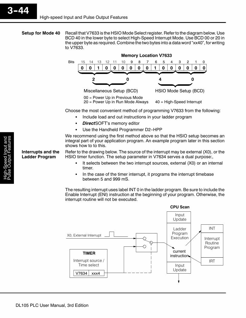
High-Speed
Inputand
Pulse
OutputFeatures
3--44High-speed Input and Pulse Output Features
DL105 PLC User Manual, 3rd Edition
Recall that V7633 is theHSIOModeSelect register. Refer to the diagrambelow.UseBCD 40 in the lower byte to select High-Speed Interrupt Mode. Use BCD 00 or 20 intheupper byte as required.Combine the twobytes into adataword “xx40”, forwritingto V7633.
015 14 13 12
Memory Location V763311 10 123456789Bits
001 00000100
HSIO Mode Setup (BCD)Miscellaneous Setup (BCD)
0 0 0 0
00 = Power Up in Previous Mode20 = Power Up in Run Mode Always 40 = High-Speed Interrupt
2 0 04
0
Choose the most convenient method of programming V7633 from the following:S Include load and out instructions in your ladder programS DirectSOFT’s memory editorS Use the Handheld Programmer D2--HPP
We recommend using the first method above so that the HSIO setup becomes anintegral part of your application program. An example program later in this sectionshows how to to this.Refer to the drawing below. The source of the interrupt may be external (X0), or theHSIO timer function. The setup parameter in V7634 serves a dual purpose:,
S It selects between the two interrupt sources, external (X0) or an internaltimer.
S In the case of the timer interrupt, it programs the interrupt timebasebetween 5 and 999 mS.
The resulting interrupt uses label INT 0 in the ladder program. Be sure to include theEnable Interrupt (ENI) instruction at the beginning of your program. Otherwise, theinterrupt routine will not be executed.
X0, External Interrupt
CPU Scan
Interrupt source /Time select
V7634 xxx4
InputUpdate
LadderProgramExecution
InputUpdate
currentinstruction
INT
InterruptRoutineProgram
IRT
TIMER
Setup for Mode 40
Interrupts and theLadder Program

High-S
peedInputand
Pulse
OutputF
eatures3--45
High-Speed Input and Pulse Output Features
DL105 PLC User Manual, 3rd Edition
Signal pulses at X0 must meet certain timing criteria to guarantee an interrupt willresult. Refer to the timing diagram below. The input characteristics of X0 are fixed (itis not a programmable filtered input). The minimum pulse width is 0.1 mS. Theremust be some delay before the next interrupt pulse arrives, such that the interruptperiod cannot be smaller than 0.5 mS.
Time
ExternalInterrupt X0
0.1 mS minimum
0.5 mS minimum
When the timed interrupt is selected, the HSIO generates the interrupt to ladderlogic. There is no interrupt “pulse width” in this case, but the interrupt period can beadjusted from 5 to 999 mS.
Time
TimedInterrupt
5 mS to 999 mS
The configurable discrete input options for High-Speed Interrupt Mode are listed inthe table below. Input X0 is the external interrupt when “0004” is in V7634. If youneed a timed interrupt instead, then V7634 contains the interrupt time period, andinput X0 becomes a filtered input (uses X1’s filter time constant by default). InputsX1, X2, and X3 can only be filtered inputs, having individual configuration registersand filter time constants. However, X0 will have the same filter time constant as X1when the timed interrupt is selected.
Input ConfigurationRegister
Function Hex CodeRequired
X0 V7634 External Interrupt 0004
Uses X1’s codein V7635
Filtered Input (when timedinterrupt is in use)
0054 to 9994, which isthe timed INT timebase
X1 V7635 Filtered Input xx06 (xx = filter time)
X2 V7636 Filtered Input xx06 (xx = filter time)
X3 V7637 Filtered Input xx06 (xx = filter time)
External InterruptTiming Parameters
Timed InterruptParameters
X Input / TimedINT Configuration
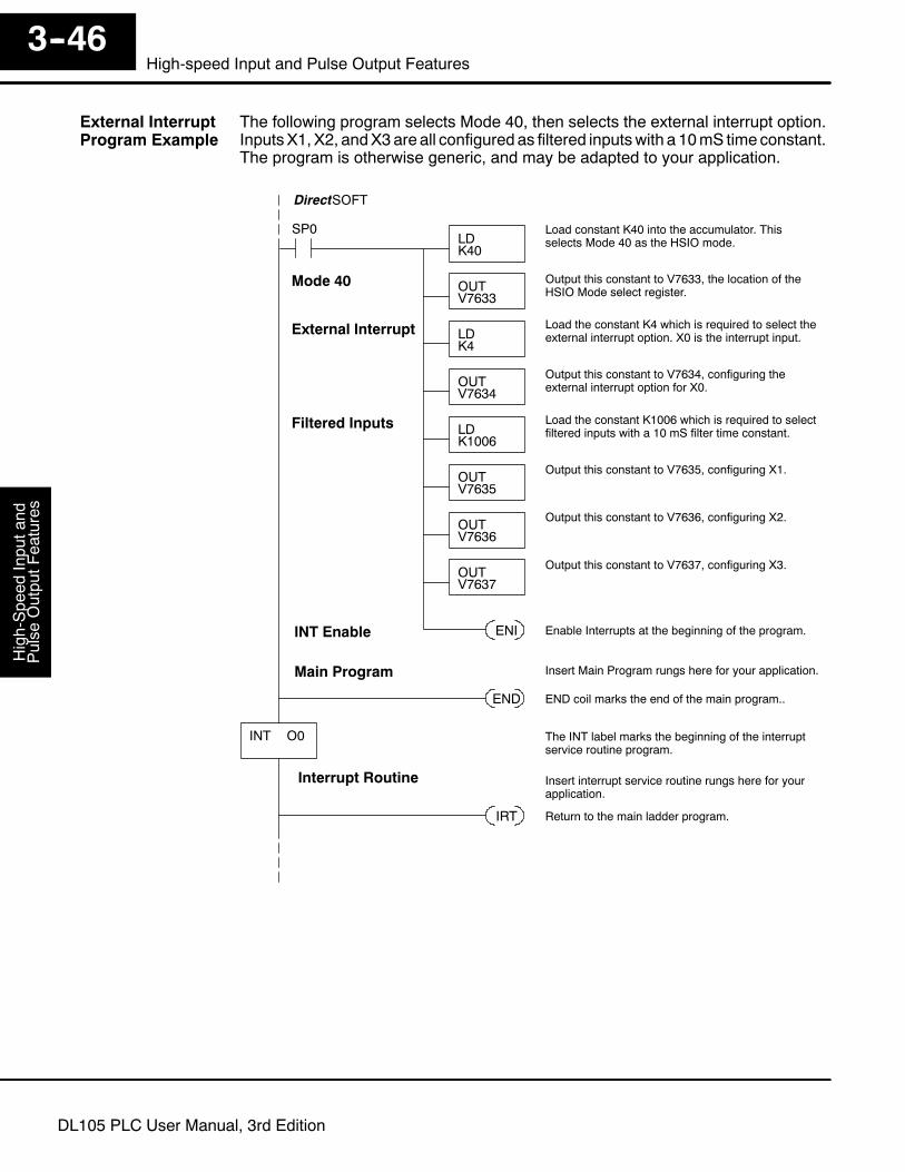
High-Speed
Inputand
Pulse
OutputFeatures
3--46High-speed Input and Pulse Output Features
DL105 PLC User Manual, 3rd Edition
The following program selects Mode 40, then selects the external interrupt option.InputsX1, X2, andX3are all configured as filtered inputswith a 10mS time constant.The program is otherwise generic, and may be adapted to your application.
SP0LDK40
Load constant K40 into the accumulator. Thisselects Mode 40 as the HSIO mode.
OUTV7633
Output this constant to V7633, the location of theHSIO Mode select register.
DirectSOFT
Mode 40
LDK1006
Load the constant K1006 which is required to selectfiltered inputs with a 10 mS filter time constant.
OUTV7635
Output this constant to V7635, configuring X1.
Filtered Inputs
OUTV7636
Output this constant to V7636, configuring X2.
OUTV7637
Output this constant to V7637, configuring X3.
LDK4
Load the constant K4 which is required to select theexternal interrupt option. X0 is the interrupt input.
OUTV7634
Output this constant to V7634, configuring theexternal interrupt option for X0.
External Interrupt
INT Enable ENI Enable Interrupts at the beginning of the program.
END END coil marks the end of the main program..
INT O0
IRT Return to the main ladder program.
The INT label marks the beginning of the interruptservice routine program.
Main Program Insert Main Program rungs here for your application.
Interrupt Routine Insert interrupt service routine rungs here for yourapplication.
External InterruptProgram Example

High-S
peedInputand
Pulse
OutputF
eatures3--47
High-Speed Input and Pulse Output Features
DL105 PLC User Manual, 3rd Edition
The following program selects Mode 40, then selects the timed interrupt option, withan interrupt period of 100 mS.
Time
TimedInterrupt
100 mS
Inputs X0, X1, X2, and X3 are all configured as filtered inputs with a 10 mS timeconstant. Note that X0 uses the time constant from X1. The program is otherwisegeneric, and may be adapted to your application.
SP0LDK40
Load constant K40 into the accumulator. Thisselects Mode 40 as the HSIO mode.
OUTV7633
Output this constant to V7633, the location of theHSIO Mode select register.
DirectSOFT
Mode 40
LDK1006
Load the constant K1006 which is required to selectfiltered inputs with a 10 mS filter time constant.
OUTV7635
Output this constant to V7635, configuring X1 and X0.
Filtered Inputs
OUTV7636
Output this constant to V7636, configuring X2.
OUTV7637
Output this constant to V7637, configuring X3.
LDK1004
Load the constant K1004 which is required to selectthe timed interrrupt option, with a period of 100 mS.
OUTV7634
Output this constant to V7634, configuring the timedinterrupt for 100 mS period.
Timed Interrupt
INT Enable ENI Enable Interrupts at the beginning of the program.
END END coil marks the end of the main program..
INT O0
IRT Return to the main ladder program.
The INT label marks the beginning of the interruptservice routine program.
Main Program Insert Main Program rungs here for your application.
Interrupt Routine Insert interrupt service routine rungs here for yourapplication.
Timed InterruptProgram Example
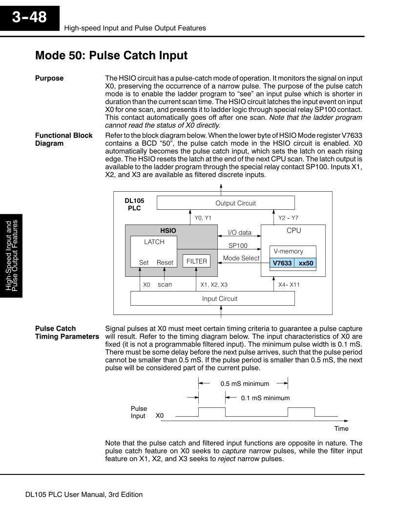
High-Speed
Inputand
Pulse
OutputFeatures
3--48High-speed Input and Pulse Output Features
DL105 PLC User Manual, 3rd Edition
Mode 50: Pulse Catch Input
TheHSIO circuit has a pulse-catchmode of operation. It monitors the signal on inputX0, preserving the occurrence of a narrow pulse. The purpose of the pulse catchmode is to enable the ladder program to “see” an input pulse which is shorter induration than the current scan time. TheHSIOcircuit latches the input event on inputX0 for one scan, and presents it to ladder logic through special relay SP100 contact.This contact automatically goes off after one scan. Note that the ladder programcannot read the status of X0 directly.Refer to the block diagrambelow.When the lower byte ofHSIOMode registerV7633contains a BCD “50”, the pulse catch mode in the HSIO circuit is enabled. X0automatically becomes the pulse catch input, which sets the latch on each risingedge. The HSIO resets the latch at the end of the next CPU scan. The latch output isavailable to the ladder program through the special relay contact SP100. Inputs X1,X2, and X3 are available as filtered discrete inputs.
Output Circuit
Input Circuit
CPU
PLCDL105
X0
Y0, Y1
X4-- X11
Y2 -- Y7
V-memory
V7633 xx50Mode Select
I/O dataHSIO
LATCH
Set Reset
X1, X2, X3scan
SP100
FILTER
Signal pulses at X0 must meet certain timing criteria to guarantee a pulse capturewill result. Refer to the timing diagram below. The input characteristics of X0 arefixed (it is not a programmable filtered input). The minimum pulse width is 0.1 mS.There must be some delay before the next pulse arrives, such that the pulse periodcannot be smaller than 0.5 mS. If the pulse period is smaller than 0.5 mS, the nextpulse will be considered part of the current pulse.
Time
PulseInput X0
0.1 mS minimum
0.5 mS minimum
Note that the pulse catch and filtered input functions are opposite in nature. Thepulse catch feature on X0 seeks to capture narrow pulses, while the filter inputfeature on X1, X2, and X3 seeks to reject narrow pulses.
Purpose
Functional BlockDiagram
Pulse CatchTiming Parameters

High-S
peedInputand
Pulse
OutputF
eatures3--49
High-Speed Input and Pulse Output Features
DL105 PLC User Manual, 3rd Edition
Recall that V7633 is theHSIOModeSelect register. Refer to the diagrambelow.UseBCD 50 in the lower byte to select High-Speed Counter Mode. Use BCD 00 or 20 intheupper byte as required.Combine the twobytes into adataword “xx50”, forwritingto V7633.
015 14 13 12
Memory Location V763311 10 123456789Bits
001 00010100
HSIO Mode Setup (BCD)Miscellaneous Setup (BCD)
0 0 0 0
00 = Power Up in Previous Mode20 = Power Up in Run Mode Always 50 = Pulse Catch Input
2 0 05
0
Choose the most convenient method of programming V7633 from the following:S Include load and out instructions in your ladder programS DirectSOFT’s memory editorS Use the Handheld Programmer D2--HPP
We recommend using the first method above so that the HSIO setup becomes anintegral part of your application program. An example program later in this sectionshows how to to this.
The configurable discrete input options for Pulse Catch Mode are listed in the tablebelow. Input X0 is the pulse input, and must have “0005” loaded into it configurationregister V7634. Inputs X1, X2, and X3 can only be filtered inputs. Each input has itsown configuration register and filter time constant.
Input ConfigurationRegister
Function Hex CodeRequired
X0 V7634 Pulse Catch Input 0005
X1 V7635 Filtered Input xx06 (xx = filter time)
X2 V7636 Filtered Input xx06 (xx = filter time)
X3 V7637 Filtered Input xx06 (xx = filter time)
Setup for Mode 50
X InputConfiguration

High-Speed
Inputand
Pulse
OutputFeatures
3--50High-speed Input and Pulse Output Features
DL105 PLC User Manual, 3rd Edition
The following program selects Mode 50, then programs the pulse catch code for X0.InputsX1, X2, andX3are all configured as filtered inputswith 10, 30, and 50mS timeconstants respectively. The program is otherwise generic, and may be adapted toyour application.
SP0LDK50
Load constant K50 into the accumulator. Thisselects Mode 50 as the HSIO mode.
OUTV7633
Output this constant to V7633, the location of theHSIO Mode select register.
DirectSOFT
Mode 50
LDK1006
Load the constant K1006 which is required to selectfiltered inputs with a 10 mS filter time constant.
OUTV7635
Output this constant to V7635, configuring X1.
Filtered Inputs
OUTV7636
Output this constant to V7636, configuring X2.
OUTV7637
Output this constant to V7637, configuring X3.
LDK5
Load the constant K5 which is required to configure X0as the pulse catch input.
OUTV7634
Output this constant to V7634, configuring the pulsecatch option for X0.
Pulse Catch
END END coil marks the end of the main program..
Main Program
Use the pulse catch input to set output Y0 on. This willwork even for a very short pulse on X0.
LDK3006
Load the constant K3006 which is required to selectfiltered inputs with a 30 mS filter time constant.
LDK5006
Load the constant K5006 which is required to selectfiltered inputs with a 50 mS filter time constant.
SP100
SETY0
Pulse CatchProgram Example
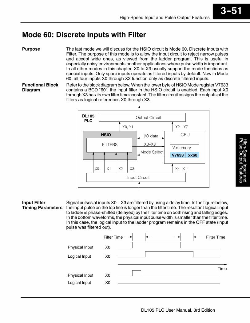
High-S
peedInputand
Pulse
OutputF
eatures3--51
High-Speed Input and Pulse Output Features
DL105 PLC User Manual, 3rd Edition
Mode 60: Discrete Inputs with Filter
The last mode we will discuss for the HSIO circuit is Mode 60, Discrete Inputs withFilter. The purpose of this mode is to allow the input circuit to reject narrow pulsesand accept wide ones, as viewed from the ladder program. This is useful inespecially noisy environments or other applications where pulse width is important.In all other modes in this chapter, X0 to X3 usually support the mode functions asspecial inputs. Only spare inputs operate as filtered inputs by default. Now in Mode60, all four inputs X0 through X3 function only as discrete filtered inputs.Refer to the block diagrambelow.When the lower byte ofHSIOMode registerV7633contains a BCD “60”, the input filter in the HSIO circuit is enabled. Each input X0throughX3has its own filter time constant. The filter circuit assigns the outputs of thefilters as logical references X0 through X3.
Output Circuit
Input Circuit
CPU
PLCDL105
X0
Y0, Y1
X4-- X11
Y2 -- Y7
V-memory
V7633 xx60Mode Select
I/O dataHSIO
FILTERS X0--X3
X1 X2 X3
Signal pulses at inputs X0 -- X3 are filtered by using a delay time. In the figure below,the input pulse on the top line is longer than the filter time. The resultant logical inputto ladder is phase-shifted (delayed) by the filter time on both rising and falling edges.In the bottomwaveforms, the physical input pulsewidth is smaller than the filter time.In this case, the logical input to the ladder program remains in the OFF state (inputpulse was filtered out).
Time
Physical Input X0
Filter Time
Logical Input X0
Physical Input X0
Logical Input X0
Filter Time
Purpose
Functional BlockDiagram
Input FilterTiming Parameters
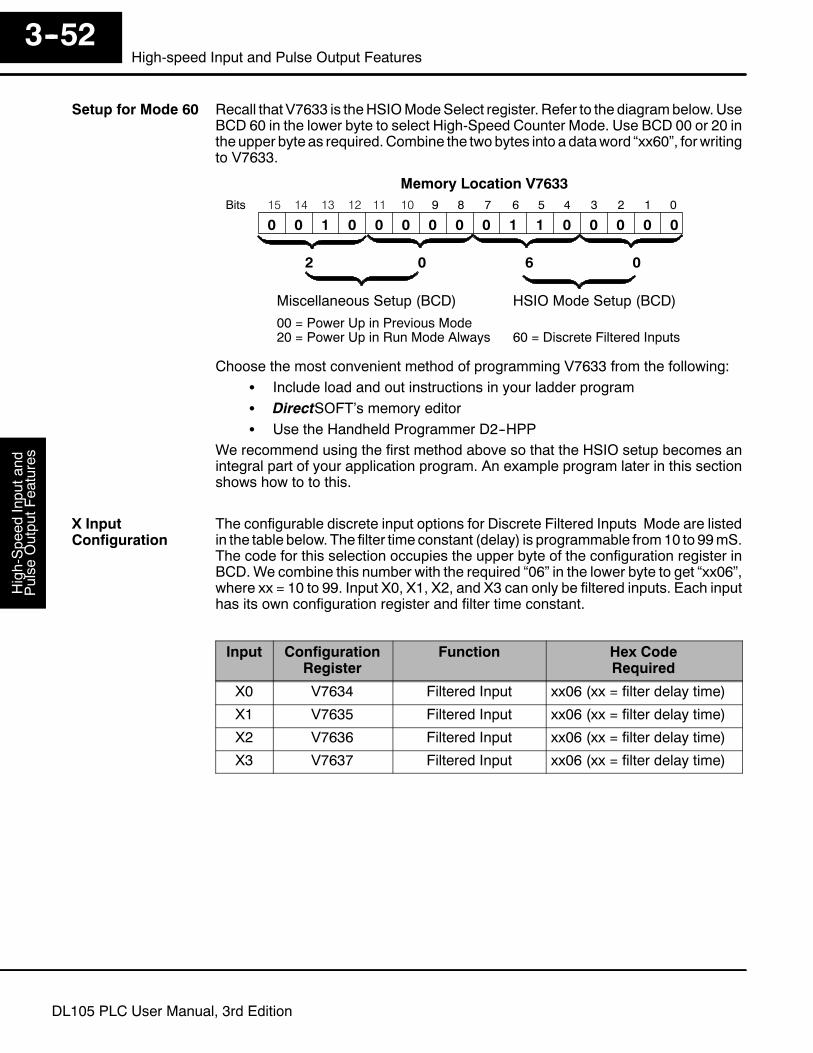
High-Speed
Inputand
Pulse
OutputFeatures
3--52High-speed Input and Pulse Output Features
DL105 PLC User Manual, 3rd Edition
Recall that V7633 is theHSIOModeSelect register. Refer to the diagrambelow.UseBCD 60 in the lower byte to select High-Speed Counter Mode. Use BCD 00 or 20 intheupper byte as required.Combine the twobytes into adataword “xx60”, forwritingto V7633.
015 14 13 12
Memory Location V763311 10 123456789Bits
001 00001100
HSIO Mode Setup (BCD)Miscellaneous Setup (BCD)
0 0 0 0
00 = Power Up in Previous Mode20 = Power Up in Run Mode Always 60 = Discrete Filtered Inputs
2 0 06
0
Choose the most convenient method of programming V7633 from the following:S Include load and out instructions in your ladder programS DirectSOFT’s memory editorS Use the Handheld Programmer D2--HPP
We recommend using the first method above so that the HSIO setup becomes anintegral part of your application program. An example program later in this sectionshows how to to this.
The configurable discrete input options for Discrete Filtered Inputs Mode are listedin the table below. The filter time constant (delay) is programmable from10 to 99mS.The code for this selection occupies the upper byte of the configuration register inBCD.We combine this number with the required “06” in the lower byte to get “xx06”,where xx = 10 to 99. Input X0, X1, X2, and X3 can only be filtered inputs. Each inputhas its own configuration register and filter time constant.
Input ConfigurationRegister
Function Hex CodeRequired
X0 V7634 Filtered Input xx06 (xx = filter delay time)
X1 V7635 Filtered Input xx06 (xx = filter delay time)
X2 V7636 Filtered Input xx06 (xx = filter delay time)
X3 V7637 Filtered Input xx06 (xx = filter delay time)
Setup for Mode 60
X InputConfiguration
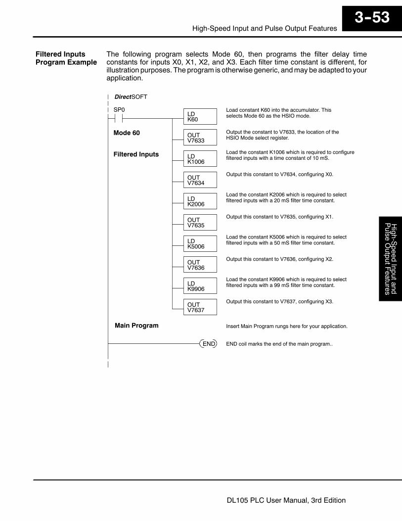
High-S
peedInputand
Pulse
OutputF
eatures3--53
High-Speed Input and Pulse Output Features
DL105 PLC User Manual, 3rd Edition
The following program selects Mode 60, then programs the filter delay timeconstants for inputs X0, X1, X2, and X3. Each filter time constant is different, forillustration purposes. The program is otherwise generic, andmay beadapted to yourapplication.
SP0LDK60
Load constant K60 into the accumulator. Thisselects Mode 60 as the HSIO mode.
OUTV7633
Output the constant to V7633, the location of theHSIO Mode select register.
DirectSOFT
Mode 60
LDK2006
Load the constant K2006 which is required to selectfiltered inputs with a 20 mS filter time constant.
OUTV7635
Output this constant to V7635, configuring X1.
Filtered Inputs
OUTV7636
Output this constant to V7636, configuring X2.
OUTV7637
Output this constant to V7637, configuring X3.
LDK1006
Load the constant K1006 which is required to configurefiltered inputs with a time constant of 10 mS.
OUTV7634
Output this constant to V7634, configuring X0.
END END coil marks the end of the main program..
Main Program Insert Main Program rungs here for your application.
LDK5006
Load the constant K5006 which is required to selectfiltered inputs with a 50 mS filter time constant.
LDK9906
Load the constant K9906 which is required to selectfiltered inputs with a 99 mS filter time constant.
Filtered InputsProgram Example