innovative techniques in non-destructive testing and
TRANSCRIPT
Procedia Engineering 46 ( 2012 ) 266 – 278
1877-7058 © 2012 The Authors. Published by Elsevier Ltd. Selection and/or peer-review under responsibility of the Scientifi c Committee of SYMPHOS 2011doi: 10.1016/j.proeng.2012.09.472
1st International Symposium on Innovation and Technology in the Phosphate Industry [SYMPHOS 2011]
Innovative Techniques in Non-Destructive Testing and Industrial Applications on Pressure Equipment
Mohammed Cherfaouia*
Centre Technique des Industries Mécaniques (CETIM), 52, avenue Félix Louat – 60300 SENLIS - France
Abstract
The average age of pressure vessels in service worldwide is increasing from year to year. A major concern of industrial operators is to ensure the security of their facilities and people, while extending the life of their fleet of pressure vessels. In this context, it is necessary to control the health of this type of structure, and also be able to assess the residual life of a device. Through a real case, the study presented in this article shows all the stages of implementation of a process that allowed initially to make an accurate diagnosis of the condition of a sphere of storage and to evaluate its lifetime, then in a second time, to ensure the operations back into compliance to ensure a reactivation of this structure. This process is fully insured by the CETIM, involved the following: • A hydraulic test with acoustic emission monitoring, • Testing additional relevant Non Destructive testing (NDT) (TOFD, Ultrasonic, Magnetic ...) • Checks by the method of metallographic replicas and / or levies, • A study of life, estimated by calculations based on NDT and metallurgical studies, • Writing a procedure recommendations repair by welding of critical defects, • The supervision during repairs and the testing after repairs. This approach is developed by Cetim based on Innovative Non destructive testing.
© 2012 The Authors. Published by Elsevier Ltd. Selection and/or peer-review under responsibility of the Selection and /or peer-review under responsibility of the scientific committee of SYMPHOS 2011.
Keywords: NDT, non destructive testing, pressure equipment, thermography, acoustic emission, calculation
1. Introduction
The term "Non-Destructive Inspections" or "Non-Destructive Testing" (NDI / NDT) reminds the diagnosis that a physician expresses during the examination of his/her patient. The same principle applied to industrial parts and equipment consists in implementing investigation methods to assess the health condition of those parts and equipment without destruction and expressing an opinion on their ability to fulfil the function which they are intended to.
When considered under this aspect of operability, the definition implies good knowledge of all the phenomena involved, in particular the harmfulness of the defects, their evolution over time and the general laws of failure mechanics. In practice, Non-Destructive Testing specialists are rather faced with problems of interpretation of the inspection results with respect to
* * Corresponding author. Tel.: +33-(0)3.44.67.33.18 E-mail address: [email protected]
Available online at www.sciencedirect.com
© 2012 The Authors. Published by Elsevier Ltd. Selection and/or peer-review under responsibility of the Scientifi c Committee of SYMPHOS 2011 Open access under CC BY-NC-ND license.
Open access under CC BY-NC-ND license.
brought to you by COREView metadata, citation and similar papers at core.ac.uk
provided by Elsevier - Publisher Connector
267 Mohammed Cherfaoui / Procedia Engineering 46 ( 2012 ) 266 – 278
criteria established in cooperation with the designer of the part. Therefore, a definition of Non-Destructive Inspections more in line with industrial reality consists in saying that the
purpose is to "qualify, without necessarily quantifying, the condition of a product without altering its characteristics with respect to acceptance standards".
The execution of this task requires good knowledge of the investigation methods implemented, their limits and above all perfect adequacy between the detection power of each method and the criteria applied for implementation. Therefore, one will understand that great importance is attached to the training of Non-Destructive Testing operators.
The purpose of this article is to demonstrate how much these techniques stemming from the medical field have contributed to the industrial world. They have developed first in the transport industry (aeronautics, railway, car manufacturing, etc.) and in the energy sector (nuclear, oil, chemical industries, etc.).
Examples of application will be dealt with in the case of pressure equipment, such equipment being subject to regulations in order to control the pressure risk.
2. Main non-destructive testing methods
The non-destructive testing methods [1] which are most currently used can be classified in two main families depending on the type of anomaly searched for in the part:
Surface inspection methods (anomalies on the outer surface): Visual testing (VT) Penetrant testing (PT) Magnetic particle testing (MT) Eddy current testing (ET)
Volumetric inspection methods (anomalies within the part): Ultrasonic, conventional, TOFD, Phased array testing (UT) Radiography testing (RT) , tomography testing Guided wave (specific to pipes and tubes …)
Other methods exist and they have the advantage of being overall and real time. These are, in particular: Active thermography Acoustic emission
This list of methods is far from exhaustive. We still could mention, among others, sealing, whose complexity of implementation can significantly vary depending on the type and size of the anomalies searched for, or else those methods which use particular effects to characterise materials or parts (Barkhausen effect for instance). At last, new methods are emerging: FAST, non-linear methods, etc.
We will only deal with 2 methods in this article.
3. Contribution of simulation and phased array techniques
In the field of non-destructive testing of materials, the phased array ultrasonic technology offers many advantages: better sensitivity and accuracy thanks to beam focusing, imaging, traceability or also fast execution of an inspection, etc.
Designing an inspection which implements such a technology for a complex industrial case requires simultaneous setting of several parameters (type of transducer, position and displacements of the transducer, calculation of the time delay laws, etc.).
CETIM still uses the CIVA software to design complex inspection solutions. The view of the ultrasound beam within the part and the study of its interaction with the geometry and the defects make it possible to study the feasibility of the inspection, propose solutions of improvement and demonstrate the performance of these solutions.
The work carried out showed the consistency between the numerical and experimental results obtained within the framework of the development of a phased array ultrasonic inspection of a multiple-section shaft. These results therefore substantiate the use of simulation to design realistic inspection solutions (figure 1 to 3).
3.1 Context and ultrasonic testing
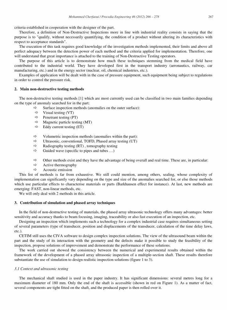
The mechanical shaft studied is used in the paper industry. It has significant dimensions: several metres long for a maximum diameter of 180 mm. Only the end of the shaft is accessible (shown in red on Figure 1). As a matter of fact, several components are tight fitted on the shaft, and the produced paper is then rolled over it.
268 Mohammed Cherfaoui / Procedia Engineering 46 ( 2012 ) 266 – 278
Figure 1: Presentation of the shaft in its industrial context: awaiting (left), with rolled paper (right)
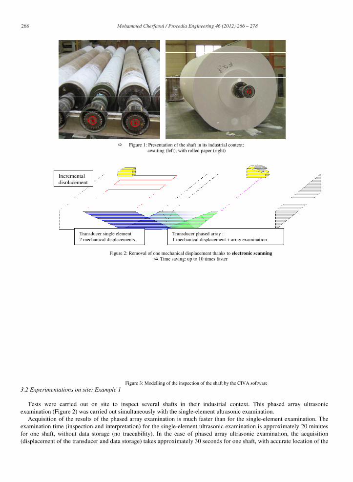
Figure 2: Removal of one mechanical displacement thanks to electronic scanning Time saving: up to 10 times faster
Figure 3: Modelling of the inspection of the shaft by the CIVA software3.2 Experimentations on site: Example 1
Tests were carried out on site to inspect several shafts in their industrial context. This phased array ultrasonic examination (Figure 2) was carried out simultaneously with the single-element ultrasonic examination.
Acquisition of the results of the phased array examination is much faster than for the single-element examination. The examination time (inspection and interpretation) for the single-element ultrasonic examination is approximately 20 minutes for one shaft, without data storage (no traceability). In the case of phased array ultrasonic examination, the acquisition (displacement of the transducer and data storage) takes approximately 30 seconds for one shaft, with accurate location of the
Transducer single element 2 mechanical displacements
Transducer phased array : 1 mechanical displacement + array examination
Incremental displacement
269 Mohammed Cherfaoui / Procedia Engineering 46 ( 2012 ) 266 – 278
indications. The analysis of the results takes from 3 to 5 minutes for the entire shaft. Time saving, improved accuracy, easier interpretation and better result traceability provided by the phased array
examinations are therefore the main advantages of this technology for this type of inspection.
4. Contribution of active thermography
Today, infrared thermography has become the reference method in many applications such as inspection of electrical facilities or inspection of the thermal insulation of buildings. But in the last years, the evolutions of the equipment and the data processing tools have also allowed thermography to become a full NDT method.
Therefore, by subjecting the inspected component to a controlled external excitation and by analysing the propagation of heat in the examined zone, it is possible to detect surface or subsurface defects such as cracks, delamination, or corrosion. In this case, this is active infrared thermography.
We will present here the various possibilities provided by active thermography and we will discuss the interest of this method with respect to conventional methods and their future use.
4.1. Principle
Infrared thermography is an inspection method widely used in the diagnosis of buildings or the inspection of electrical cabinets [2]. It consists in acquiring, using a thermal camera, the heat flux naturally emitted by the examined body. In this case, this is passive infrared thermography. The image obtained, called "thermograph", can therefore reveal an abnormal variation of the thermal flux and evidence a defect.
However, in the case of applications in Non-destructive testing, production or maintenance, the parts to be inspected often do not emit heat. By disturbing the analysed sample through heating and by analysing its thermal response, it is possible to have access to data which is not transmitted spontaneously. This is therefore active infrared thermography. In the case of faulty parts, the analysis of the sequence of images makes it possible to detect heat transfer discontinuities. It is therefore possible to detect and determine the dimensions of these discontinuities which correspond to the defects (delamination, cracks, water infiltration, etc.).
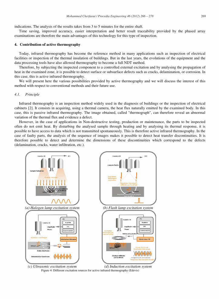
(a) Halogen lamp excitation system (b) Flash lamp excitation system
(c) Ultrasonic excitation system (d) Induction excitation system Figure 4: Different excitation sources for active infrared thermography (Edevis)
270 Mohammed Cherfaoui / Procedia Engineering 46 ( 2012 ) 266 – 278
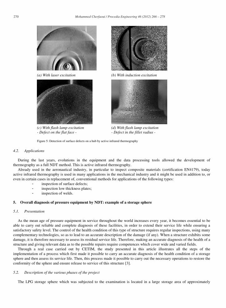
(a) With laser excitation (b) With induction excitation
(c) With flash lamp excitation - Defect on the flat face -
(d) With flash lamp excitation - Defect in the fillet radius -
Figure 5: Detection of surface defects on a hub by active infrared thermography
4.2. Applications
During the last years, evolutions in the equipment and the data processing tools allowed the development of thermography as a full NDT method. This is active infrared thermography.
Already used in the aeronautical industry, in particular to inspect composite materials (certification EN4179), today active infrared thermography is used in many applications in the mechanical industry and it might be used in addition to, or even in certain cases in replacement of, conventional methods for applications of the following types:
- inspection of surface defects; - inspection low thickness plates; - inspection of welds.
5. Overall diagnosis of pressure equipment by NDT: example of a storage sphere
5.1. Presentation
As the mean age of pressure equipment in service throughout the world increases every year, it becomes essential to be able to carry out reliable and complete diagnosis of these facilities, in order to extend their service life while ensuring a satisfactory safety level. The control of the health condition of this type of structure requires regular inspections, using many complementary technologies, so as to lead to an accurate description of the damage (if any). When a structure exhibits some damage, it is therefore necessary to assess its residual service life. Therefore, making an accurate diagnosis of the health of a structure and giving relevant data as to the possible repairs require competences which cover wide and varied fields.
Through a real case carried out by CETIM, the study presented in this article illustrates all the steps of the implementation of a process which first made it possible to carry an accurate diagnosis of the health condition of a storage sphere and then assess its service life. Then, this process made it possible to carry out the necessary operations to restore the conformity of the sphere and ensure release to service of this structure [3].
5.2. Description of the various phases of the project
The LPG storage sphere which was subjected to the examination is located in a large storage area of approximately
271 Mohammed Cherfaoui / Procedia Engineering 46 ( 2012 ) 266 – 278
15,000 m3. The target in the scope of this project was to carry out all the necessary operations to assess the integrity of this sphere,
and in the end, to be able to release it to service. The various steps are described in the paragraphs below.
A process, composed of six steps, was proposed and implemented: • A hydraulic test with acoustic emission testing, to provide an overall assessment of the sphere, • Targeted additional inspections (TOFD, ultrasonic, magnetic particle, etc.), • Metallographic inspections by means of the replica method and sampling of boat-shaped specimens, • Assessment of the service life, estimated through calculations, based on the NDT and on the metallurgical studies, • Drafting of a recommendation procedure for repair of critical defects by welding, supervision of repairs, • Inspection after repair.
5.3. Experimentation, Phase 1: Acoustic emission testing
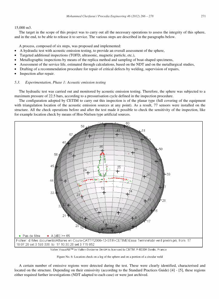
The hydraulic test was carried out and monitored by acoustic emission testing. Therefore, the sphere was subjected to a maximum pressure of 22.5 bars, according to a pressurisation cycle defined in the inspection procedure.
The configuration adopted by CETIM to carry out this inspection is of the planar type (full covering of the equipment with triangulation location of the acoustic emission sources at any point). As a result, 77 sensors were installed on the structure. All the check operations before and after the test made it possible to check the sensitivity of the inspection, like for example location check by means of Hsu-Nielsen type artificial sources.
Figure No. 6: Location check on a leg of the sphere and on a portion of a circular weld
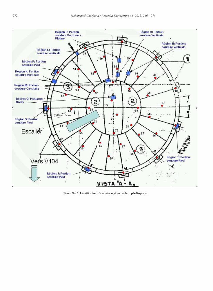
A certain number of emissive regions were detected during the test. These were clearly identified, characterised and located on the structure. Depending on their emissivity (according to the Standard Practices Guide) [4] - [5], these regions either required further investigations (NDT adapted to each case) or were just archived.
272 Mohammed Cherfaoui / Procedia Engineering 46 ( 2012 ) 266 – 278
Figure No. 7: Identification of emissive regions on the top half-sphere
273 Mohammed Cherfaoui / Procedia Engineering 46 ( 2012 ) 266 – 278
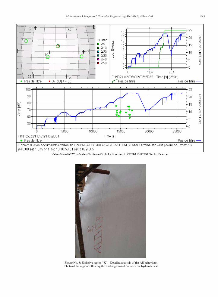
Figure No. 8: Emissive region “K” – Detailed analysis of the AE behaviour, Photo of the region following the tracking carried out after the hydraulic test
274 Mohammed Cherfaoui / Procedia Engineering 46 ( 2012 ) 266 – 278
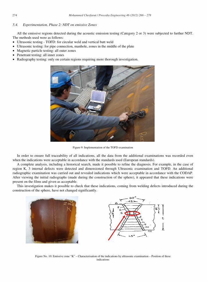
5.4. Experimentation, Phase 2: NDT on emissive Zones
All the emissive regions detected during the acoustic emission testing (Category 2 or 3) were subjected to further NDT. The methods used were as follows: • Ultrasonic testing - TOFD: for circular weld and vertical butt weld • Ultrasonic testing: for pipe connection, manhole, zones in the middle of the plate • Magnetic particle testing: all outer zones • Penetrant testing: all inner zones • Radiography testing: only on certain regions requiring more thorough investigation.
Figure 9: Implementation of the TOFD examination
In order to ensure full traceability of all indications, all the data from the additional examinations was recorded even when the indications were acceptable in accordance with the standards used (European standards).
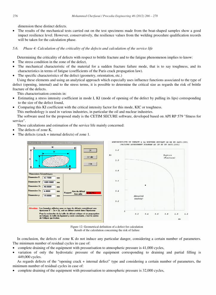
A complete analysis, including a historical search, made it possible to refine the diagnosis. For example, in the case of region K, 3 internal defects were detected and dimensioned through Ultrasonic examination and TOFD. An additional radiographic examination was carried out and revealed indications which were acceptable in accordance with the CODAP. After viewing the initial radiographs (made during the construction of the sphere), it appeared that these indications were present on the films and given as acceptable.
This investigation makes it possible to check that these indications, coming from welding defects introduced during the construction of the sphere, have not changed significantly.
Figure No. 10: Emissive zone “K” – Characterisation of the indications by ultrasonic examination – Position of these indications

275 Mohammed Cherfaoui / Procedia Engineering 46 ( 2012 ) 266 – 278
Three cracked zones located at the weld beads had been detected by magnetic particle testing (zones which had not been revealed by the acoustic emission testing). In order to obtain more data concerning the dimension of these cracks, CETIM implemented several techniques (conventional ultrasonic examination, phased array ultrasonic examination, TOFD). As it was difficult to distinguish these indications, CETIM recommended to flush machine the weld bead (with a perfectly flat surface condition) in order to carry out more accurate ultrasonic examinations and try to determine the dimensions of these indications more accurately.
The combination of these techniques made it possible to accurately determine the dimensions of two cracked zones. Note that the last crack is detectable only by magnetic particle testing.
This specific case demonstrates that it is necessary to combine different technologies to obtain a complete and accurate diagnosis. Remaining objective and trying to understand the results obtained allows technical progress to be made. Additional investigations will make it possible to give relevant explanations as to these defects and their ability to be detected by any non-destructive testing method.
5.5. Experimentation, Phase 3: Replicas and metallurgical sampling
This part brought many technical and objective elements. It made it possible to answer certain questions raised during the previous steps.
Metallurgical replicas were made on the cracked zones detected by magnetic particle and ultrasonic examinations. They made it possible to confirm the presence of opening defects and to check the metallurgical condition of the welded zone.
In order to fully characterise these defects and understand their root cause, it was decided to carry out a sampling operation (also called "boat-shaped" sampling). The analyses and examinations carried out in CETIM laboratories on these boat-shaped samples were as follows: • Opening of the cracks and study of the cracking planes, • Analysis of the decohesion mode with a scanning electron microscope, • Macrographic and micrographic examinations, • Making of impact test specimens on the boat-shaped sample in order to estimate a toughness value necessary for the
calculation.
Figure 11: Implementation of the boat-shaped sampling operation
After performing these various examinations, the conclusions are as follows: The morphologies and the dimensions measured showed 2 types of defects:
• Surface opening crack. This crack is shallow; it probably occurred during the manufacturing process and has almost not changed. As the cracking planes are dulled and as the crack is not changing, this explains why it was not detected by the acoustic emission testing.
• Internal defect, which is a lack of fusion probably due to incorrect configuration of the welding chamfer. Again, as its possible evolution is very slow, this explains why it was not detected by the acoustic emission testing.
• These metallurgical examinations reveal shallow cracks. They explain and confirm the US, TOFD or phased array examinations which rather correctly detected the initiation of the crack and which also detected a response at a slightly bigger depth but had difficulty to correctly "see" in between. This explains why it was particularly difficult to detect any
276 Mohammed Cherfaoui / Procedia Engineering 46 ( 2012 ) 266 – 278
dimension these distinct defects. • The results of the mechanical tests carried out on the test specimens made from the boat-shaped samples show a good
impact resilience level. However, conservatively, the resilience values from the welding procedure qualification records will be taken for the calculation phase.
5.6. Phase 4: Calculation of the criticality of the defects and calculation of the service life
Determining the criticality of defects with respect to brittle fracture and to the fatigue phenomenon implies to know: • The stress condition in the zone of the defect, • The mechanical characteristic of the material for a sudden fracture failure mode, that is to say toughness, and its
characteristics in terms of fatigue (coefficients of the Paris crack propagation law). • The specific characteristics of the defect (geometry, orientation, etc.)
Using these elements and using an analytical approach which especially uses influence functions associated to the type of defect (opening, internal) and to the stress terms, it is possible to determine the critical size as regards the risk of brittle fracture of the defects.
This characterisation consists in: • Estimating a stress intensity coefficient in mode I, KI (mode of opening of the defect by pulling its lips) corresponding
to the size of the defect found, • Comparing this KI coefficient with the critical intensity factor for this mode, KIC or toughness.
This methodology is used in various industries, in particular the oil and nuclear industries. The software used for the proposed study is the CETIM SECURE software, developed based on API RP 579 "fitness for
service". These calculations and estimation of the service life mainly concerned:
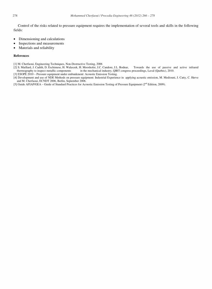
• The defects of zone K, • The defects (crack + internal defects) of zone 1.
Figure 12: Geometrical definition of a defect for calculation Result of the calculation concerning the risk of failure
In conclusion, the defects of zone K do not induce any particular danger, considering a certain number of parameters. The minimum number of residual cycles in case of: • complete draining of the equipment with pressurisation to atmospheric pressure is 41,000 cycles, • variation of only the hydrostatic pressure of the equipment corresponding to draining and partial filling is
449,000 cycles. As regards defects of the “opening crack + internal defect” type and considering a certain number of parameters, the
minimum number of residual cycles in case of: • complete draining of the equipment with pressurisation to atmospheric pressure is 32,000 cycles,

277 Mohammed Cherfaoui / Procedia Engineering 46 ( 2012 ) 266 – 278
• variation of only the hydrostatic pressure of the equipment corresponding to draining and partial filling is 530,000 cycles.
5.7. Phase 5: Recommendations for repair by welding – Supervision of repairs
The results obtained following the harmfulness study showed that the residual service life of the sphere allowed it to be kept in service and that none of the defects was harmful.
However, considering the samples taken for the metallurgical examination, and by precaution, it was decided to carry out repairs in the following zones: • zones containing surface indications: repair by grinding or opening and resurfacing by welding; • zone of the boat-shaped sample: resurfacing by welding.
CETIM gave repair recommendations for each repair zone. Following the previous phases, CETIM supervised the welding operations. This welding work was carried out in line with CETIM’s recommendations, in accordance with the welding process
qualification and in accordance with the requirements of construction code ASME Section IX. The process and the welders had been previously qualified. All the steps allowing perfect control of this operation were taken:
• Previous visual examination, • Surface preparation by grinding in order to remove all oxides, • Measurement of the opening depths, • Magnetic particle testing before and during the welding operation, • Execution of the welding process with all required heating phases, number of passes, welding parameters, etc., • Finishing by grinding. 5.8. Phase 6: Non-destructive testing of the repairs
The last step consisted in inspecting the zones of the sphere, which had undergone repairs. The different methods below were implemented:
- TOFD examination carried out from the inside and from the outside, - Ultrasonic examinations carried out with 45°, 60° and 70° sensors, - Magnetic particle testing carried out from the inside (only the repaired or resurfaced zone).
During these inspections, small linear indications were detected by the magnetic particle test; they were hardly visible with the ultrasonic testing and not detectable with the TOFD testing. These indications were very superficial and slight grinding was enough to remove them.
In conclusion, no unacceptable indication was detected by the NDT procedures carried out, on the zones concerned. The repairs were therefore validated and the sphere then becomes fit again for a hydraulic test followed-up by an approved organisation, with a view to decennial requalification in accordance with the local regulations in force. Subsequently, an inspection plan of the sphere, that is to say periodical NDTs, will be implemented by the user in order to keep the equipment under control.
5.9. Summary of the overall diagnosis
Controlling the health condition of risk structures requires regular inspections, using many complementary technologies leading to an accurate description of all possible damage. When a structure exhibits any deterioration, then it is necessary to assess its residual service life. Therefore, giving an accurate diagnosis as to the health of a structure and giving all relevant data as to any possible repairs are tasks which require skills covering wide and varied fields.
Thanks to the real case carried out by CETIM and presented in this article, one can realise the necessity of the multiple skills necessary to implement such a process: • Non-destructive testing, • Metallurgical analysis, • Calculation, • Welding, etc.
However, for a successful operation, all these actions will have to be connected, synthesised and coordinated. Thanks to its very wide field of competence, CETIM has the ideal structure to ensure this type of operations. 6. Conclusion
278 Mohammed Cherfaoui / Procedia Engineering 46 ( 2012 ) 266 – 278
Control of the risks related to pressure equipment requires the implementation of several tools and skills in the following fields:
• Dimensioning and calculations • Inspections and measurements • Materials and reliability
References
[1] M. Cherfaoui, Engineering Techniques, Non-Destructive Testing, 2006 [2] S. Maillard, J. Cadith, D. Eschimese, H. Walaszek, H. Mooshofer, J.C. Candore, J.L. Bodnar, Towards the use of passive and active infrared
thermography to inspect metallic components in the mechanical industry, QIRT congress proceedings, Laval (Quebec), 2010. [3] ESOPE 2010 – Pressure equipment under embankment: Acoustic Emission Testing. [4] Development and use of NDE Methods on pressure equipment: Industrial Experience in applying acoustic emission, M. Mediouni, J. Catty, C. Herve
and M. Cherfaoui, ECNDT 2006, Berlin, September 2006. [5] Guide AFIAP/GEA – Guide of Standard Practices for Acoustic Emission Testing of Pressure Equipment (2nd Edition, 2009).