innova 40i dro manual - amtc40i- operation/installation - dro description - (3/26) 1 dro description...
TRANSCRIPT
Innova 40i / 40i-BInstallation / Operation ManualManual code: 14460086Manual version: 0808Software version: 2.00
INDEX
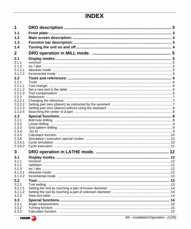
1 DRO description ........................................................................................ 31.1 Front plate: ....................................................................................................................... 31.2 Main screen description: ................................................................................................ 41.3 Function bar description: ............................................................................................... 41.4 Turning the unit on and off ............................................................................................. 42 DRO operation in MILL mode. ................................................................. 52.1 Display modes. ................................................................................................................ 52.1.1 mm/inch ...........................................................................................................................................52.1.2 inc / abs ...........................................................................................................................................52.1.2.1 Absolute mode: ................................................................................................................................52.1.2.2 Incremental mode: ...........................................................................................................................52.2 Tools and references: ..................................................................................................... 62.2.1 Tools: ...............................................................................................................................................62.2.1.1 Tool change: ....................................................................................................................................62.2.1.2 Set a new tool in the table: ...............................................................................................................62.2.1.3 Tool compensation: ..........................................................................................................................62.2.2 Reference: .......................................................................................................................................72.2.2.1 Changing the reference: ..................................................................................................................72.2.2.2 Setting part zero (datum) as instructed by the assistant: .................................................................72.2.2.3 Setting part zero (datum) without using the assistant: .....................................................................82.2.2.4 Searching the center of a part: .........................................................................................................82.3 Special functions. ............................................................................................................ 82.3.1 Bolt-hole drilling. ..............................................................................................................................82.3.2 Linear drilling. ...................................................................................................................................92.3.3 Grid pattern drilling. ..........................................................................................................................92.3.4 Go to: ..............................................................................................................................................92.3.5 Calculator function. ........................................................................................................................102.3.6 Simulation / execution special modes: ...........................................................................................102.3.6.1 Cycle simulation: ............................................................................................................................102.3.6.2 Cycle execution: .............................................................................................................................11
3 DRO operation in LATHE mode. ............................................................ 123.1 Display modes. .............................................................................................................. 123.1.1 mm/inch .........................................................................................................................................12
40i - Installation/Operation - (1/26)
3.1.2 rad/diam .........................................................................................................................................123.1.3 inc / abs .........................................................................................................................................123.1.3.1 Absolute mode: ..............................................................................................................................123.1.3.2 Incremental mode: .........................................................................................................................133.2 Tool:................................................................................................................................ 133.2.1 Tool setting: ...................................................................................................................................133.2.1.1 Setting the tool by touching a part of known diameter: ..................................................................143.2.1.2 Setting the tool by touching a part of unknown diameter: ..............................................................143.2.2 View tool table: ...............................................................................................................................143.3 Special functions. .......................................................................................................... 143.3.1 Angle measurement. ......................................................................................................................153.3.2 Turning function. ............................................................................................................................153.3.3 Calculator function. ........................................................................................................................15
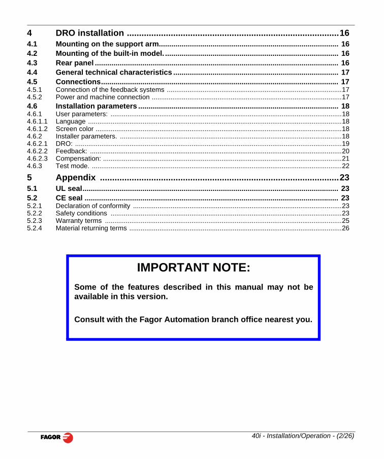
4 DRO installation .......................................................................................164.1 Mounting on the support arm....................................................................................... 164.2 Mounting of the built-in model. .................................................................................... 164.3 Rear panel ...................................................................................................................... 164.4 General technical characteristics ................................................................................ 174.5 Connections................................................................................................................... 174.5.1 Connection of the feedback systems .............................................................................................174.5.2 Power and machine connection .....................................................................................................174.6 Installation parameters ................................................................................................. 184.6.1 User parameters: ...........................................................................................................................184.6.1.1 Language .......................................................................................................................................184.6.1.2 Screen color ...................................................................................................................................184.6.2 Installer parameters. ......................................................................................................................184.6.2.1 DRO: ..............................................................................................................................................194.6.2.2 Feedback: ......................................................................................................................................204.6.2.3 Compensation: ...............................................................................................................................214.6.3 Test mode. .....................................................................................................................................22
5 Appendix ..................................................................................................235.1 UL seal............................................................................................................................ 235.2 CE seal ........................................................................................................................... 235.2.1 Declaration of conformity ...............................................................................................................235.2.2 Safety conditions ...........................................................................................................................235.2.3 Warranty terms ..............................................................................................................................255.2.4 Material returning terms .................................................................................................................26
IMPORTANT NOTE:Some of the features described in this manual may not beavailable in this version.
Consult with the Fagor Automation branch office nearest you.
40i - Installation/Operation - (2/26)
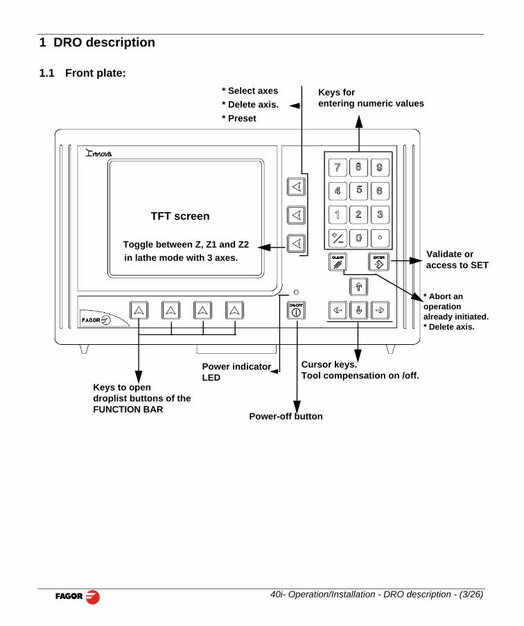
eys for ntering numeric values
Validate oraccess to SET
or keys.compensation on /off.
* Abort an operation already initiated.* Delete axis.
1 DRO description
1.1 Front plate:
TFT screen
* Select axes* Delete axis.* Preset
Ke
Power indicatorLED
Keys to opendroplist buttons of theFUNCTION BAR
Power-off button
CursTool
Toggle between Z, Z1 and Z2in lathe mode with 3 axes.
40i- Operation/Installation - DRO description - (3/26)
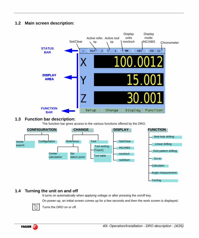
1.2 Main screen description:
1.3 Function bar description:The function bar gives access to the various functions offered by the DRO.
DISPLAYAREA
Active refer. Nr
Active toolNr
Displayunits
mm/inch
Displaymode:
INC/ABSSet/Clear Chronometer
DISPLAYAREA
DISPLAYAREA
STATUSBAR
FUNCTIONBAR
Homesearch
Configuration Reference Tool
Centercalculation
Setdatum point
Calculator
Go to
Grid pattern drilling
CONFIGURATION CHANGE DISPLAY FUNCTION
Linear drilling
Bolt-hole drilling Set/Clear
INC/ABS
mm/inch
rad/diam
Tool setting(Teach)
Tool table
40i- Operation/Installation - DRO description - (4/26)
1.4 Turning the unit on and offIt turns on automatically when applying voltage or after pressing the on/off key.
On power-up, an initial screen comes up for a few seconds and then the work screen is displayed.
Turns the DRO on or off.
Angle measurement
Turning
2 DRO operation in MILL mode.
2.1 Display modes. Display
2.1.1 mm/inch
Toggle units between mm and inches.
This toggle is possible if the installer parameters have been set as toggle .
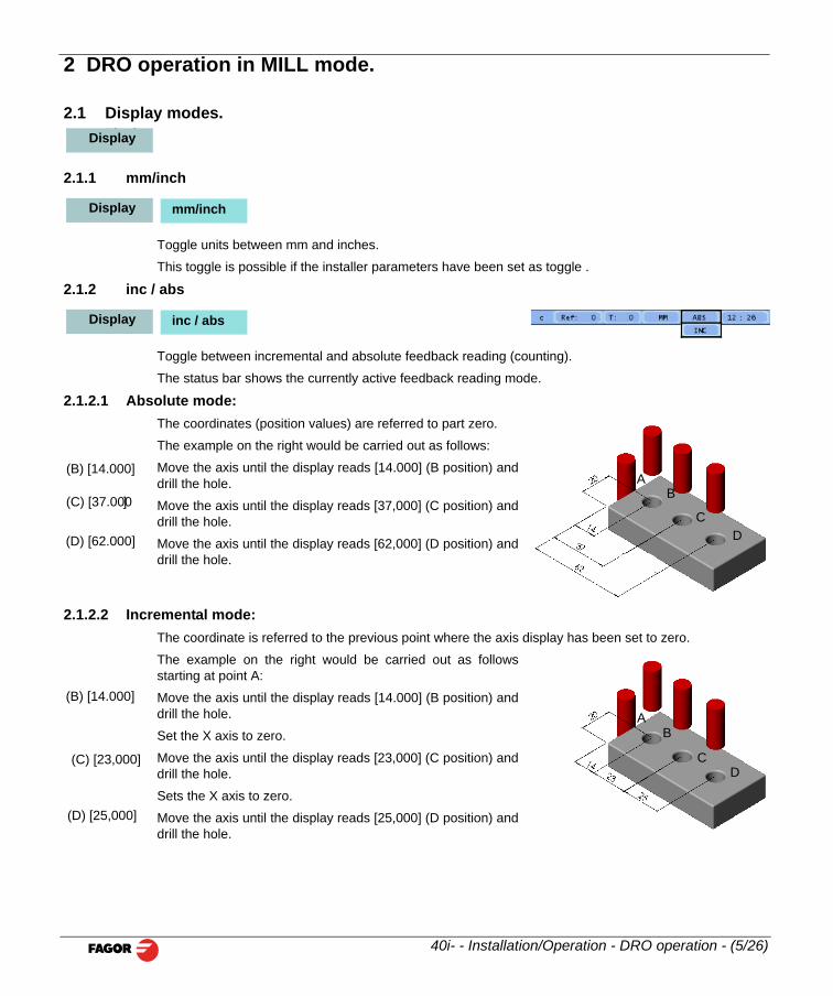
2.1.2 inc / abs
Toggle between incremental and absolute feedback reading (counting).
The status bar shows the currently active feedback reading mode.
2.1.2.1 Absolute mode:The coordinates (position values) are referred to part zero.
The example on the right would be carried out as follows:
Move the axis until the display reads [14.000] (B position) anddrill the hole.
Move the axis until the display reads [37,000] (C position) anddrill the hole.
Move the axis until the display reads [62,000] (D position) anddrill the hole.
2.1.2.2 Incremental mode:The coordinate is referred to the previous point where the axis display has been set to zero.
The example on the right would be carried out as followsstarting at point A:
Move the axis until the display reads [14.000] (B position) and
Display
Display mm/inch
Display inc / abs
B
CD
A(B) [14.000]
(C) [37.000]
(D) [62.000]
(B) [14.000]
40i- - Installation/Operation - DRO operation - (5/26)
drill the hole.
Set the X axis to zero.
Move the axis until the display reads [23,000] (C position) anddrill the hole.
Sets the X axis to zero.
Move the axis until the display reads [25,000] (D position) anddrill the hole.
B
CD
A
(C) [23,000]
(D) [25,000]
2.2 Tools and references:
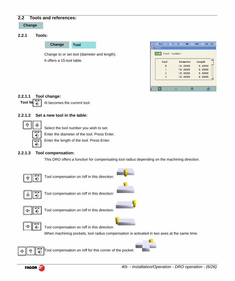
2.2.1 Tools:
Change to or set tool (diameter and length).
It offers a 15-tool table.
2.2.1.1 Tool change:IIt becomes the current tool.
2.2.1.2 Set a new tool in the table:
Select the tool number you wish to set.
Enter the diameter of the tool. Press Enter.
Enter the length of the tool. Press Enter.
2.2.1.3 Tool compensation:This DRO offers a function for compensating tool radius depending on the machining direction.
Tool compensation on /off in this direction:
Tool compensation on /off in this direction:
Change
Change Tool
Tool Nr.
40i- - Installation/Operation - DRO operation - (6/26)
Tool compensation on /off in this direction:
Tool compensation on /off in this direction:
When machining pockets, tool radius compensation is activated in two axes at the same time.
Tool compensation on /off for this corner of the pocket:
Tool compensation on /off for this corner of the pocket:
Tool compensation on /off for this corner of the pocket:
Tool compensation on /off for this corner of the pocket:
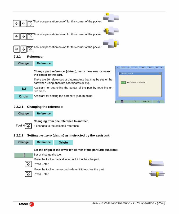
2.2.2 Reference:
Change part reference (datum), set a new one or searchthe center of the part.There are 50 references or datum points that may be set for thepart when using absolute coordinates (0-49).
Assistant for searching the center of the part by touching ontwo sides.
Assistant for setting the part zero (datum point).
2.2.2.1 Changing the reference:
Changing from one reference to another.It changes to the selected reference.
2.2.2.2 Setting part zero (datum) as instructed by the assistant:
Set the origin at the lower left corner of the part (3rd quadrant).
Change Reference
1/2
Origin
Change Reference
Tool Nr.
Change Reference Origin
40i- - Installation/Operation - DRO operation - (7/26)
Set or change the tool.
Move the tool to the first side until it touches the part.
Press Enter.
Move the tool to the second side until it touches the part.
Press Enter.
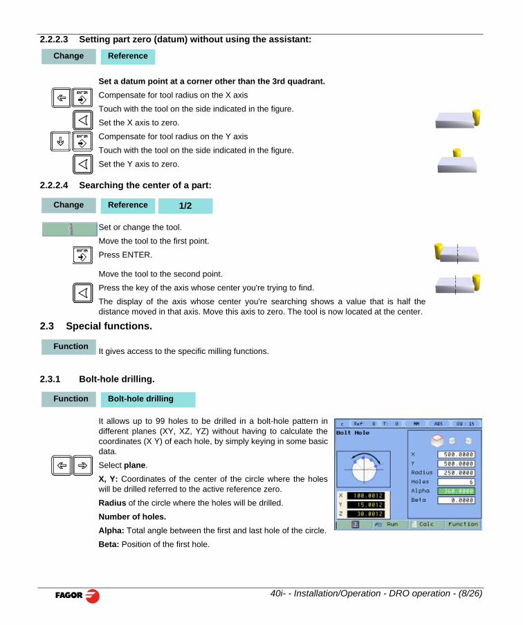
2.2.2.3 Setting part zero (datum) without using the assistant:
Set a datum point at a corner other than the 3rd quadrant.Compensate for tool radius on the X axis
Touch with the tool on the side indicated in the figure.
Set the X axis to zero.
Compensate for tool radius on the Y axis
Touch with the tool on the side indicated in the figure.
Set the Y axis to zero.
2.2.2.4 Searching the center of a part:
Set or change the tool.
Move the tool to the first point.
Press ENTER.
Move the tool to the second point.
Press the key of the axis whose center you're trying to find.
The display of the axis whose center you're searching shows a value that is half thedistance moved in that axis. Move this axis to zero. The tool is now located at the center.
2.3 Special functions.
It gives access to the specific milling functions.
2.3.1 Bolt-hole drilling.
It allows up to 99 holes to be drilled in a bolt-hole pattern indifferent planes (XY, XZ, YZ) without having to calculate thecoordinates (X Y) of each hole, by simply keying in some basic
Change Reference
Change Reference 1/2
Function
Function Bolt-hole drilling
40i- - Installation/Operation - DRO operation - (8/26)
data.
Select plane.
X, Y: Coordinates of the center of the circle where the holeswill be drilled referred to the active reference zero.
Radius of the circle where the holes will be drilled.
Number of holes.Alpha: Total angle between the first and last hole of the circle.
Beta: Position of the first hole.
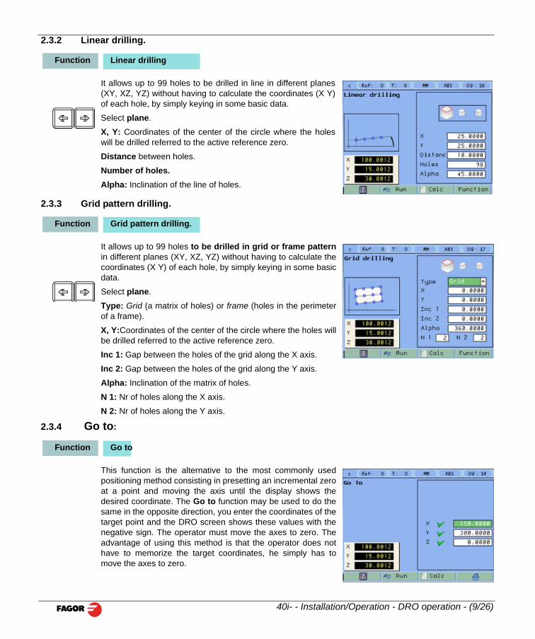
2.3.2 Linear drilling.
It allows up to 99 holes to be drilled in line in different planes(XY, XZ, YZ) without having to calculate the coordinates (X Y)of each hole, by simply keying in some basic data.
Select plane.
X, Y: Coordinates of the center of the circle where the holeswill be drilled referred to the active reference zero.
Distance between holes.
Number of holes.Alpha: Inclination of the line of holes.
2.3.3 Grid pattern drilling.
It allows up to 99 holes to be drilled in grid or frame patternin different planes (XY, XZ, YZ) without having to calculate thecoordinates (X Y) of each hole, by simply keying in some basicdata.
Select plane.
Type: Grid (a matrix of holes) or frame (holes in the perimeterof a frame).
X, Y:Coordinates of the center of the circle where the holes willbe drilled referred to the active reference zero.
Inc 1: Gap between the holes of the grid along the X axis.
Inc 2: Gap between the holes of the grid along the Y axis.
Alpha: Inclination of the matrix of holes.
N 1: Nr of holes along the X axis.
N 2: Nr of holes along the Y axis.
2.3.4 Go to:
Function Linear drilling
Function Grid pattern drilling.
Function Go to
40i- - Installation/Operation - DRO operation - (9/26)
This function is the alternative to the most commonly usedpositioning method consisting in presetting an incremental zeroat a point and moving the axis until the display shows thedesired coordinate. The Go to function may be used to do thesame in the opposite direction, you enter the coordinates of thetarget point and the DRO screen shows these values with thenegative sign. The operator must move the axes to zero. Theadvantage of using this method is that the operator does nothave to memorize the target coordinates, he simply has tomove the axes to zero.
When presetting a value on an axis, press ENTER to go on to the next axis and validate the data justentered.
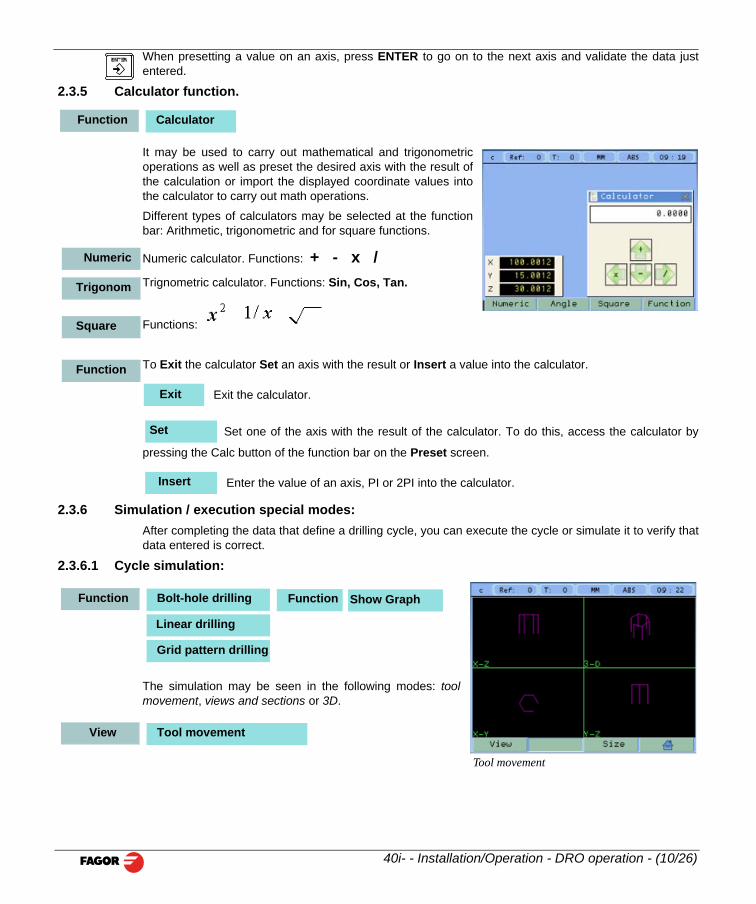
2.3.5 Calculator function.
It may be used to carry out mathematical and trigonometricoperations as well as preset the desired axis with the result ofthe calculation or import the displayed coordinate values intothe calculator to carry out math operations.
Different types of calculators may be selected at the functionbar: Arithmetic, trigonometric and for square functions.
Numeric calculator. Functions: + - x /Trignometric calculator. Functions: Sin, Cos, Tan.
Functions:
To Exit the calculator Set an axis with the result or Insert a value into the calculator.
Exit the calculator.
Set one of the axis with the result of the calculator. To do this, access the calculator by
pressing the Calc button of the function bar on the Preset screen.
Enter the value of an axis, PI or 2PI into the calculator.
2.3.6 Simulation / execution special modes:After completing the data that define a drilling cycle, you can execute the cycle or simulate it to verify thatdata entered is correct.
2.3.6.1 Cycle simulation:
Function Calculator
Numeric
Trigonom
Square
Function
Exit
Set
Insert
Function Bolt-hole drilling
Linear drilling
Function Show Graph
40i- - Installation/Operation - DRO operation - (10/26)
The simulation may be seen in the following modes: toolmovement, views and sections or 3D.
Tool movement
Grid pattern drilling
View Tool movement
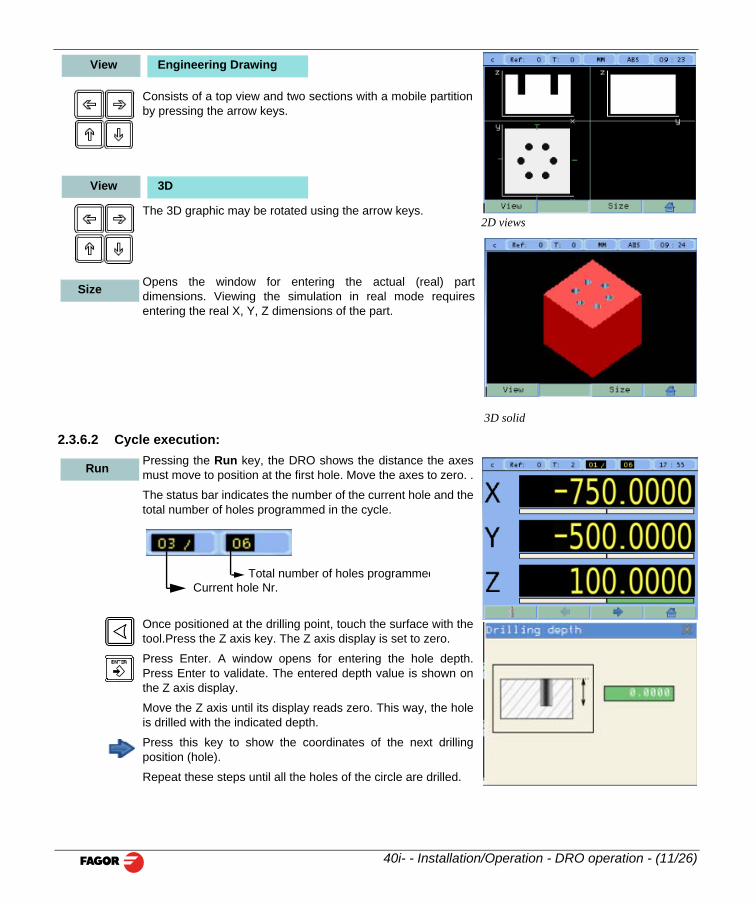
Consists of a top view and two sections with a mobile partitionby pressing the arrow keys.
The 3D graphic may be rotated using the arrow keys.
Opens the window for entering the actual (real) partdimensions. Viewing the simulation in real mode requiresentering the real X, Y, Z dimensions of the part.
2.3.6.2 Cycle execution:Pressing the Run key, the DRO shows the distance the axesmust move to position at the first hole. Move the axes to zero. .
The status bar indicates the number of the current hole and thetotal number of holes programmed in the cycle.
Once positioned at the drilling point, touch the surface with thetool.Press the Z axis key. The Z axis display is set to zero.
2D views
View Engineering Drawing
View 3D
3D solid
Size
Run
Current hole Nr.Total number of holes programmed
40i- - Installation/Operation - DRO operation - (11/26)
Press Enter. A window opens for entering the hole depth.Press Enter to validate. The entered depth value is shown onthe Z axis display.
Move the Z axis until its display reads zero. This way, the holeis drilled with the indicated depth.
Press this key to show the coordinates of the next drillingposition (hole).
Repeat these steps until all the holes of the circle are drilled.
3 DRO operation in LATHE mode.
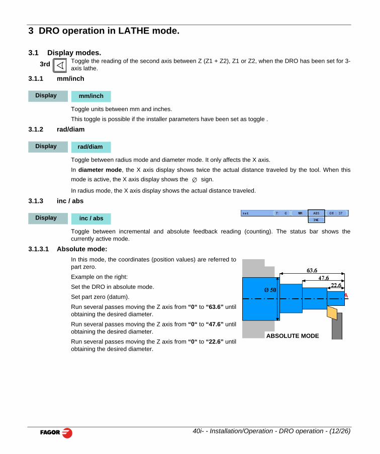
3.1 Display modes. Toggle the reading of the second axis between Z (Z1 + Z2), Z1 or Z2, when the DRO has been set for 3-axis lathe.
3.1.1 mm/inch
Toggle units between mm and inches.
This toggle is possible if the installer parameters have been set as toggle .
3.1.2 rad/diam
Toggle between radius mode and diameter mode. It only affects the X axis.
In diameter mode, the X axis display shows twice the actual distance traveled by the tool. When thismode is active, the X axis display shows the sign.
In radius mode, the X axis display shows the actual distance traveled.
3.1.3 inc / abs
ñ
Toggle between incremental and absolute feedback reading (counting). The status bar shows thecurrently active mode.
3.1.3.1 Absolute mode:In this mode, the coordinates (position values) are referred topart zero.
Example on the right:
Set the DRO in absolute mode.
Set part zero (datum).
Run several passes moving the Z axis from “0“ to “63.6” untilobtaining the desired diameter.
3rd
Display mm/inch
Display rad/diam
Display inc / abs
A
40i- - Installation/Operation - DRO operation - (12/26)
Run several passes moving the Z axis from “0“ to “47.6” untilobtaining the desired diameter.
Run several passes moving the Z axis from “0“ to “22.6” untilobtaining the desired diameter.
ABSOLUTE MODE
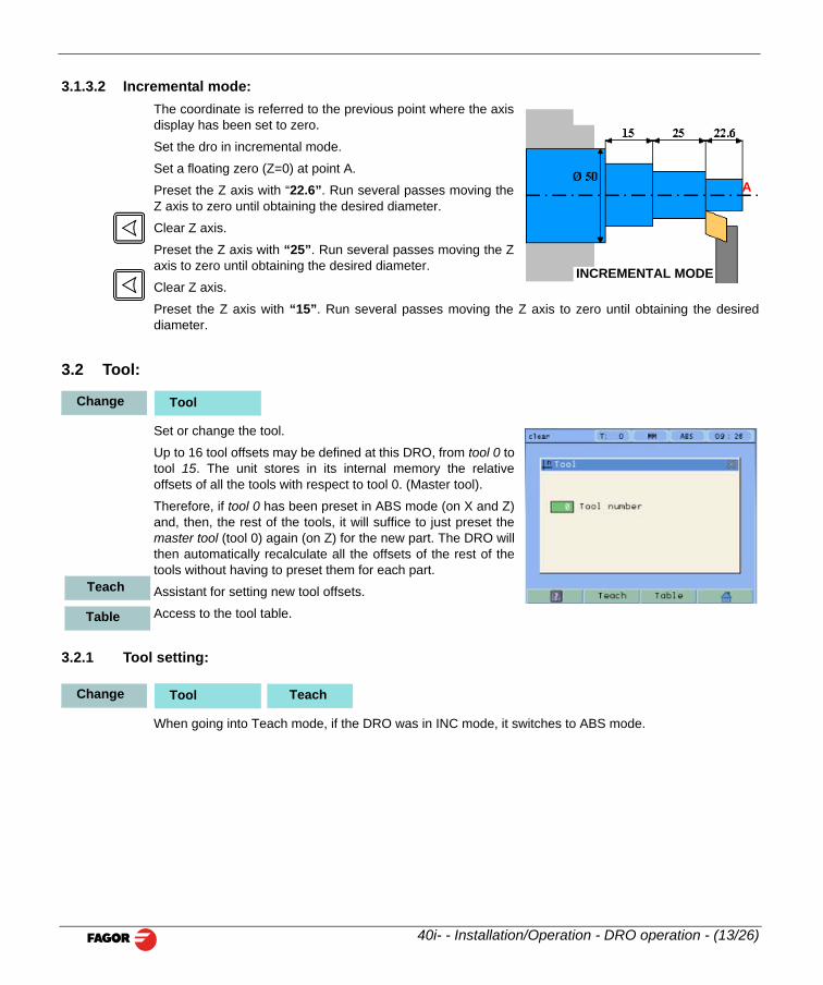
3.1.3.2 Incremental mode:The coordinate is referred to the previous point where the axisdisplay has been set to zero.
Set the dro in incremental mode.
Set a floating zero (Z=0) at point A.
Preset the Z axis with “22.6”. Run several passes moving theZ axis to zero until obtaining the desired diameter.
Clear Z axis.
Preset the Z axis with “25”. Run several passes moving the Zaxis to zero until obtaining the desired diameter.
Clear Z axis.
Preset the Z axis with “15”. Run several passes moving the Z axis to zero until obtaining the desireddiameter.
3.2 Tool:
Set or change the tool.
Up to 16 tool offsets may be defined at this DRO, from tool 0 totool 15. The unit stores in its internal memory the relativeoffsets of all the tools with respect to tool 0. (Master tool).
Therefore, if tool 0 has been preset in ABS mode (on X and Z)and, then, the rest of the tools, it will suffice to just preset themaster tool (tool 0) again (on Z) for the new part. The DRO willthen automatically recalculate all the offsets of the rest of thetools without having to preset them for each part.
Assistant for setting new tool offsets.
Access to the tool table.
3.2.1 Tool setting:
INCREMENTAL MODE
A
Change Tool
Teach
Table
Change Tool Teach
40i- - Installation/Operation - DRO operation - (13/26)
When going into Teach mode, if the DRO was in INC mode, it switches to ABS mode.
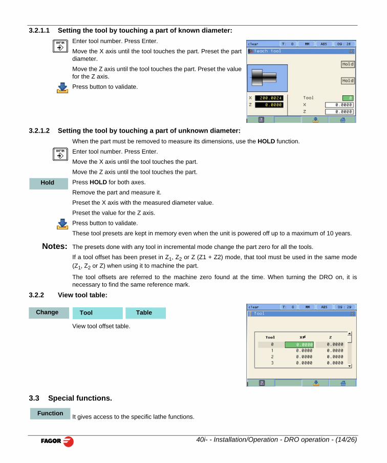
3.2.1.1 Setting the tool by touching a part of known diameter:Enter tool number. Press Enter.
Move the X axis until the tool touches the part. Preset the partdiameter.
Move the Z axis until the tool touches the part. Preset the valuefor the Z axis.
Press button to validate.
3.2.1.2 Setting the tool by touching a part of unknown diameter:When the part must be removed to measure its dimensions, use the HOLD function.
Enter tool number. Press Enter.
Move the X axis until the tool touches the part.
Move the Z axis until the tool touches the part.
Press HOLD for both axes.
Remove the part and measure it.
Preset the X axis with the measured diameter value.
Preset the value for the Z axis.
Press button to validate.
These tool presets are kept in memory even when the unit is powered off up to a maximum of 10 years.
Notes: The presets done with any tool in incremental mode change the part zero for all the tools.
If a tool offset has been preset in Z1, Z2 or Z (Z1 + Z2) mode, that tool must be used in the same mode(Z1, Z2 or Z) when using it to machine the part.
The tool offsets are referred to the machine zero found at the time. When turning the DRO on, it isnecessary to find the same reference mark.
3.2.2 View tool table:
View tool offset table.
Hold
Change Tool Table
40i- - Installation/Operation - DRO operation - (14/26)
3.3 Special functions.
It gives access to the specific lathe functions.Function
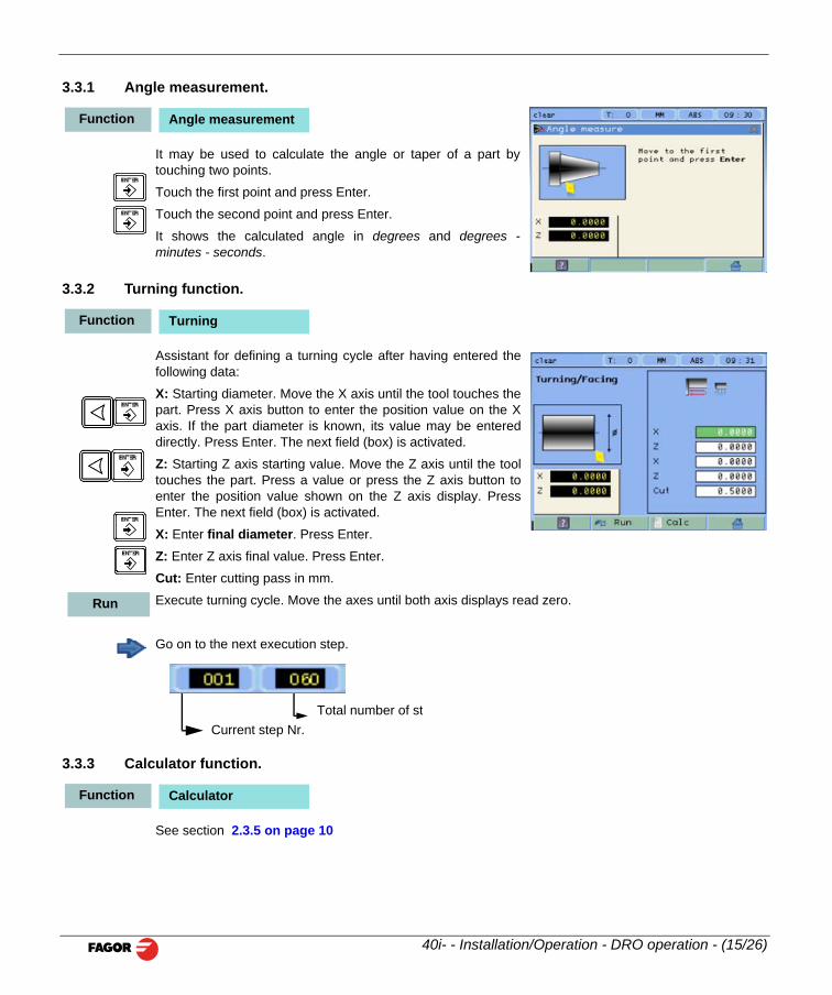
3.3.1 Angle measurement.
It may be used to calculate the angle or taper of a part bytouching two points.
Touch the first point and press Enter.
Touch the second point and press Enter.
It shows the calculated angle in degrees and degrees -minutes - seconds.
3.3.2 Turning function.
Assistant for defining a turning cycle after having entered thefollowing data:
X: Starting diameter. Move the X axis until the tool touches thepart. Press X axis button to enter the position value on the Xaxis. If the part diameter is known, its value may be entereddirectly. Press Enter. The next field (box) is activated.
Z: Starting Z axis starting value. Move the Z axis until the tooltouches the part. Press a value or press the Z axis button toenter the position value shown on the Z axis display. PressEnter. The next field (box) is activated.
X: Enter final diameter. Press Enter.
Z: Enter Z axis final value. Press Enter.
Cut: Enter cutting pass in mm.
Execute turning cycle. Move the axes until both axis displays read zero.
Go on to the next execution step.
Function Angle measurement
Function Turning
Run
40i- - Installation/Operation - DRO operation - (15/26)
3.3.3 Calculator function.
See section 2.3.5 on page 10
Current step Nr.Total number of st
Function Calculator
4 DRO installation
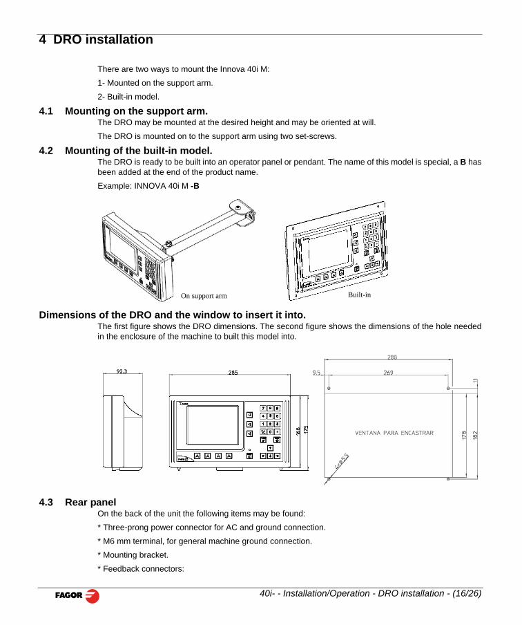
There are two ways to mount the Innova 40i M:
1- Mounted on the support arm.
2- Built-in model.
4.1 Mounting on the support arm.The DRO may be mounted at the desired height and may be oriented at will.
The DRO is mounted on to the support arm using two set-screws.
4.2 Mounting of the built-in model.The DRO is ready to be built into an operator panel or pendant. The name of this model is special, a B hasbeen added at the end of the product name.
Example: INNOVA 40i M -B
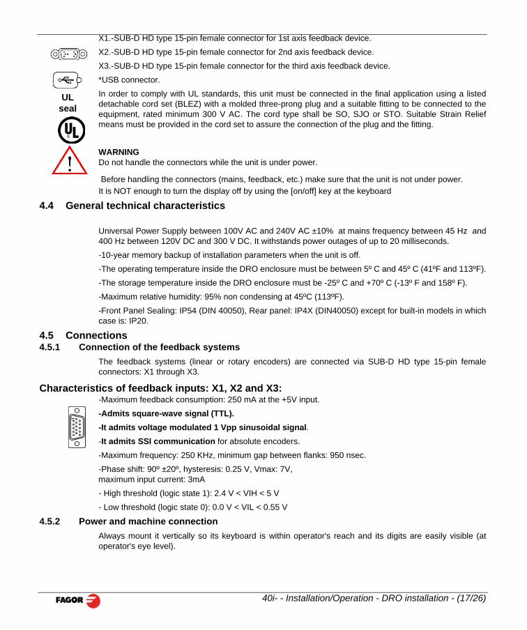
Dimensions of the DRO and the window to insert it into.The first figure shows the DRO dimensions. The second figure shows the dimensions of the hole neededin the enclosure of the machine to built this model into.
On support arm Built-in
40i- - Installation/Operation - DRO installation - (16/26)
4.3 Rear panelOn the back of the unit the following items may be found:
* Three-prong power connector for AC and ground connection.
* M6 mm terminal, for general machine ground connection.
* Mounting bracket.
* Feedback connectors:
X1.-SUB-D HD type 15-pin female connector for 1st axis feedback device.
X2.-SUB-D HD type 15-pin female connector for 2nd axis feedback device.
X3.-SUB-D HD type 15-pin female connector for the third axis feedback device.
*USB connector.
In order to comply with UL standards, this unit must be connected in the final application using a listeddetachable cord set (BLEZ) with a molded three-prong plug and a suitable fitting to be connected to theequipment, rated minimum 300 V AC. The cord type shall be SO, SJO or STO. Suitable Strain Reliefmeans must be provided in the cord set to assure the connection of the plug and the fitting.
WARNINGDo not handle the connectors while the unit is under power.
Before handling the connectors (mains, feedback, etc.) make sure that the unit is not under power. It is NOT enough to turn the display off by using the [on/off] key at the keyboard
4.4 General technical characteristics
Universal Power Supply between 100V AC and 240V AC ±10% at mains frequency between 45 Hz and400 Hz between 120V DC and 300 V DC. It withstands power outages of up to 20 milliseconds.
-10-year memory backup of installation parameters when the unit is off.
-The operating temperature inside the DRO enclosure must be between 5º C and 45º C (41ºF and 113ºF).
-The storage temperature inside the DRO enclosure must be -25º C and +70º C (-13º F and 158º F).
-Maximum relative humidity: 95% non condensing at 45ºC (113ºF).
-Front Panel Sealing: IP54 (DIN 40050), Rear panel: IP4X (DIN40050) except for built-in models in whichcase is: IP20.
4.5 Connections4.5.1 Connection of the feedback systems
The feedback systems (linear or rotary encoders) are connected via SUB-D HD type 15-pin femaleconnectors: X1 through X3.
Characteristics of feedback inputs: X1, X2 and X3:-Maximum feedback consumption: 250 mA at the +5V input.
-Admits square-wave signal (TTL).-It admits voltage modulated 1 Vpp sinusoidal signal.-It admits SSI communication for absolute encoders.
ULseal
1
40i- - Installation/Operation - DRO installation - (17/26)
-Maximum frequency: 250 KHz, minimum gap between flanks: 950 nsec.
-Phase shift: 90º ±20º, hysteresis: 0.25 V, Vmax: 7V, maximum input current: 3mA
- High threshold (logic state 1): 2.4 V < VIH < 5 V
- Low threshold (logic state 0): 0.0 V < VIL < 0.55 V
4.5.2 Power and machine connectionAlways mount it vertically so its keyboard is within operator's reach and its digits are easily visible (atoperator's eye level).
Do not connect or disconnect the DRO connectors while it is under power.
Connect all metallic parts to a common point on the machine tool and it to the general ground point. Usecables of enough gage (no thinner than 8 mm 2 ) for this connection.
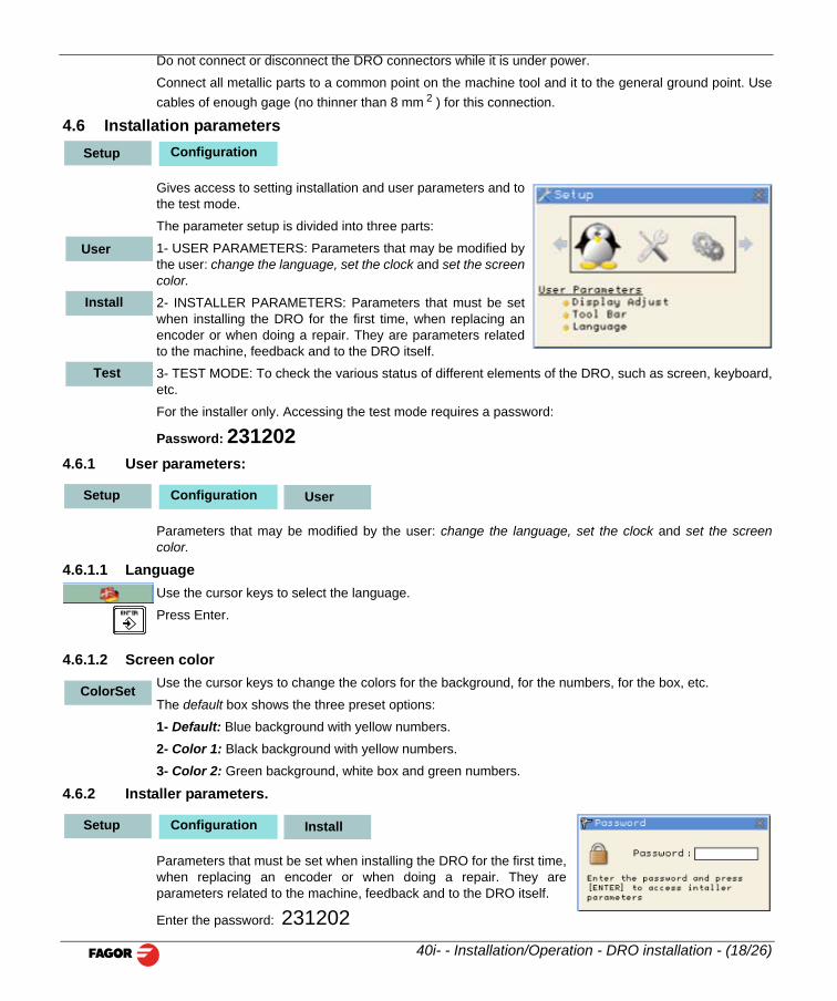
4.6 Installation parameters
Gives access to setting installation and user parameters and tothe test mode.
The parameter setup is divided into three parts:
1- USER PARAMETERS: Parameters that may be modified bythe user: change the language, set the clock and set the screencolor.
2- INSTALLER PARAMETERS: Parameters that must be setwhen installing the DRO for the first time, when replacing anencoder or when doing a repair. They are parameters relatedto the machine, feedback and to the DRO itself.
3- TEST MODE: To check the various status of different elements of the DRO, such as screen, keyboard,etc.
For the installer only. Accessing the test mode requires a password:
Password: 2312024.6.1 User parameters:
Parameters that may be modified by the user: change the language, set the clock and set the screencolor.
4.6.1.1 LanguageUse the cursor keys to select the language.
Press Enter.
4.6.1.2 Screen colorUse the cursor keys to change the colors for the background, for the numbers, for the box, etc.
ConfigurationSetup
User
Install
Test
ConfigurationSetup User
ColorSet
40i- - Installation/Operation - DRO installation - (18/26)
The default box shows the three preset options:
1- Default: Blue background with yellow numbers.
2- Color 1: Black background with yellow numbers.
3- Color 2: Green background, white box and green numbers.
4.6.2 Installer parameters.
Parameters that must be set when installing the DRO for the first time,when replacing an encoder or when doing a repair. They areparameters related to the machine, feedback and to the DRO itself.
Enter the password: 231202
ConfigurationSetup Install
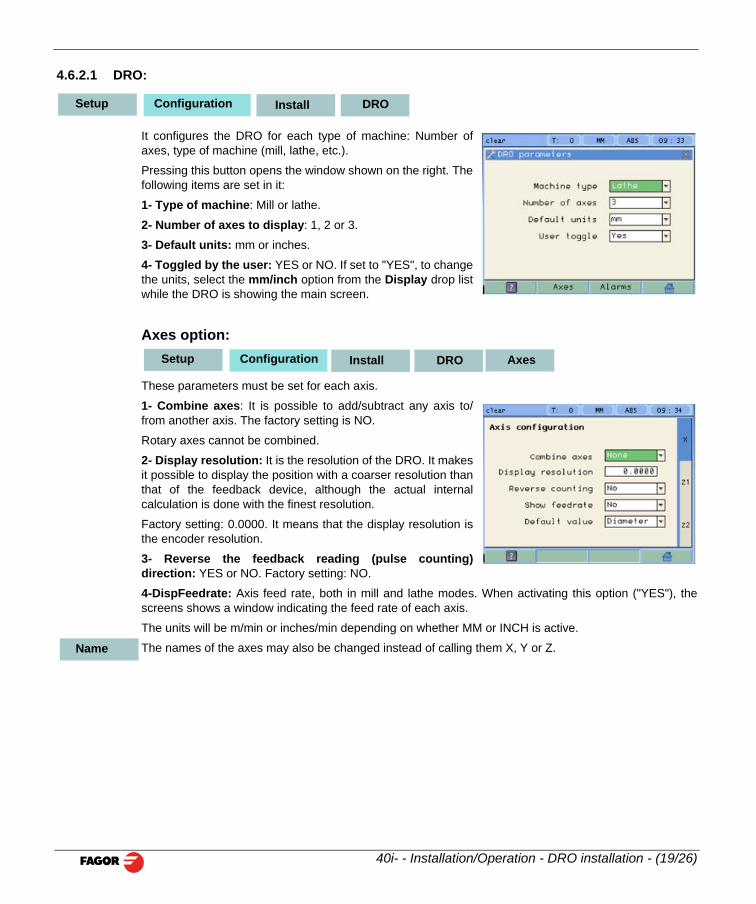
4.6.2.1 DRO:
It configures the DRO for each type of machine: Number ofaxes, type of machine (mill, lathe, etc.).
Pressing this button opens the window shown on the right. Thefollowing items are set in it:
1- Type of machine: Mill or lathe.
2- Number of axes to display: 1, 2 or 3.
3- Default units: mm or inches.
4- Toggled by the user: YES or NO. If set to "YES", to changethe units, select the mm/inch option from the Display drop listwhile the DRO is showing the main screen.
Axes option:
These parameters must be set for each axis.
1- Combine axes: It is possible to add/subtract any axis to/from another axis. The factory setting is NO.
Rotary axes cannot be combined.
2- Display resolution: It is the resolution of the DRO. It makesit possible to display the position with a coarser resolution thanthat of the feedback device, although the actual internalcalculation is done with the finest resolution.
Factory setting: 0.0000. It means that the display resolution isthe encoder resolution.
3- Reverse the feedback reading (pulse counting)direction: YES or NO. Factory setting: NO.
4-DispFeedrate: Axis feed rate, both in mill and lathe modes. When activating this option ("YES"), thescreens shows a window indicating the feed rate of each axis.
The units will be m/min or inches/min depending on whether MM or INCH is active.
ConfigurationSetup Install DRO
ConfigurationSetup Install DRO Axes
40i- - Installation/Operation - DRO installation - (19/26)
The names of the axes may also be changed instead of calling them X, Y or Z. Name
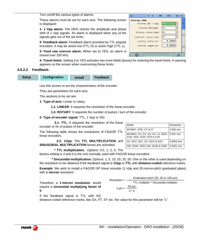
Turn on/off the various types of alarms.
These alarms must be set for each axis. The following screenis displayed:
1- 1 Vpp alarm: The DRO checks the amplitude and phaseshift of 1 Vpp signals. An alarm is displayed when any of thesignals gets out of the set limits.
2- Feedback alarm: Feedback alarm provided by TTL angularencoders. It may be active low (TTL O) or active high (TTL 1).
3- Feed rate overrun alarm: When set to YES, an alarm isissued over 200 kHz.
4- Travel limits: Setting it to YES activates two more fields (boxes) for entering the travel limits. A warningappears on the screen when overrunning these limits.
4.6.2.2 Feedback:
Use this screen to set the characteristics of the encoder.
They are parameters for each axis.
The sections to be set are:
1- Type of axis: Linear or rotary.
1.1- LINEAR: It requests the resolution of the linear encoder.
1.2- ROTARY: It requests the number of pulses / turn of the encoder.
2- Type of encoder signal: TTL, 1 Vpp or SSI.
2.1- TTL: It requests the resolution of the linearencoder or Nr of pulses of the encoder.
The following table shows the resolutions of FAGOR TTLlinear encoders.
2.2- 1Vpp: The TTL MULTIPLICATION andSINUSOIDAL MULTIPLICATION boxes are activated.
* TTL multiplication. Options: 0.5, 1, 2, 4. Thefactory setting is 4 and it is the one normally used with FAGOR linear encoders.
* Sinusoidal multiplication. Options: 1, 5, 10, 20, 25, 50. One or the other is used depending onthe resolution to be obtained if the feedback signal is 1Vpp or TTL with distance-coded reference marks.
ConfigurationSetup Install Feedback
Model Resolution
MT/MKT, MTD, CT & FT 0.005 mm
MX/MKX, CX, SX, GX, FX, LX, MOX,COX, SOX, GOX, FOX & LOX
0.001 mm
SY, SOY, SSY, GY, GOY & GSY 0.0005 mm
SW, SOW, SSW, GW, GOW & GSW 0.0001 mm
40i- - Installation/Operation - DRO installation - (20/26)
Example: We wish to install a FAGOR GP linear encoder (1 Vpp and 20-micron-pitch graduated glass)with 1 micron resolution.
:
Therefore, a 1-micron resolution, wouldrequire a sinusoidal multiplying factor of5.
If the feedback signal is TTL with NOdistance-coded reference marks, like GX, FT, SY etc. the value for this parameter will be "1".
Resolution =Graduation pitch (20, 40 or 100 µm)TTL multiplier * Sinusoidal multiplier
1 µm =20 µm4 * 5
If the feedback signal is TTL with NO distance-coded reference marks, like GX, FT, SY etc. the value forthis parameter will be "1".
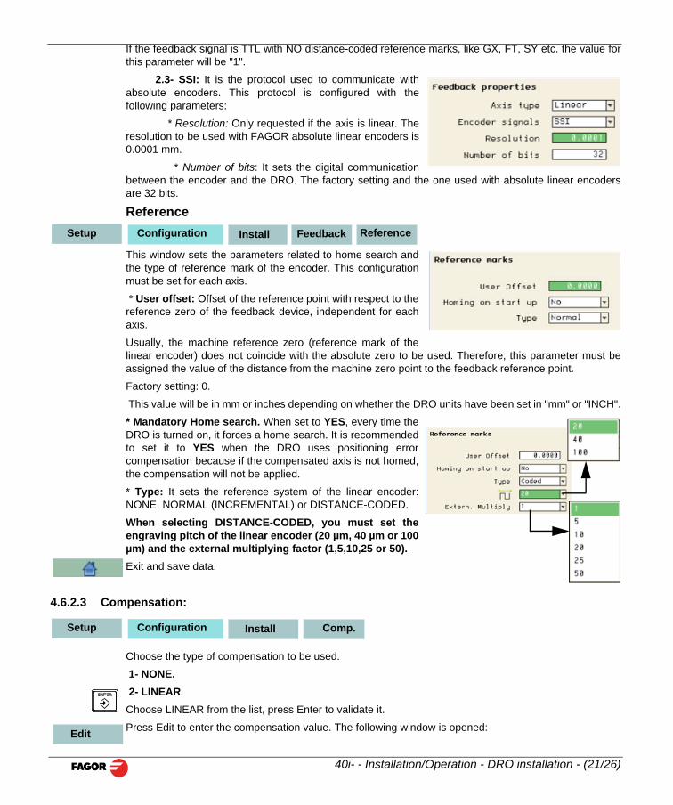
2.3- SSI: It is the protocol used to communicate withabsolute encoders. This protocol is configured with thefollowing parameters:
* Resolution: Only requested if the axis is linear. Theresolution to be used with FAGOR absolute linear encoders is0.0001 mm.
* Number of bits: It sets the digital communicationbetween the encoder and the DRO. The factory setting and the one used with absolute linear encodersare 32 bits.
Reference
This window sets the parameters related to home search andthe type of reference mark of the encoder. This configurationmust be set for each axis.
* User offset: Offset of the reference point with respect to thereference zero of the feedback device, independent for eachaxis.
Usually, the machine reference zero (reference mark of thelinear encoder) does not coincide with the absolute zero to be used. Therefore, this parameter must beassigned the value of the distance from the machine zero point to the feedback reference point.
Factory setting: 0.
This value will be in mm or inches depending on whether the DRO units have been set in "mm" or "INCH".
* Mandatory Home search. When set to YES, every time theDRO is turned on, it forces a home search. It is recommendedto set it to YES when the DRO uses positioning errorcompensation because if the compensated axis is not homed,the compensation will not be applied.
* Type: It sets the reference system of the linear encoder:NONE, NORMAL (INCREMENTAL) or DISTANCE-CODED.
When selecting DISTANCE-CODED, you must set theengraving pitch of the linear encoder (20 µm, 40 µm or 100µm) and the external multiplying factor (1,5,10,25 or 50).
ConfigurationSetup Install Feedback Reference
40i- - Installation/Operation - DRO installation - (21/26)
Exit and save data.
4.6.2.3 Compensation:
Choose the type of compensation to be used.
1- NONE. 2- LINEAR.
Choose LINEAR from the list, press Enter to validate it.
Press Edit to enter the compensation value. The following window is opened:
ConfigurationSetup Install Comp.
Edit
Even when working in inches, this value must always be in mm.
Enter the linear compensation value and press Enter.
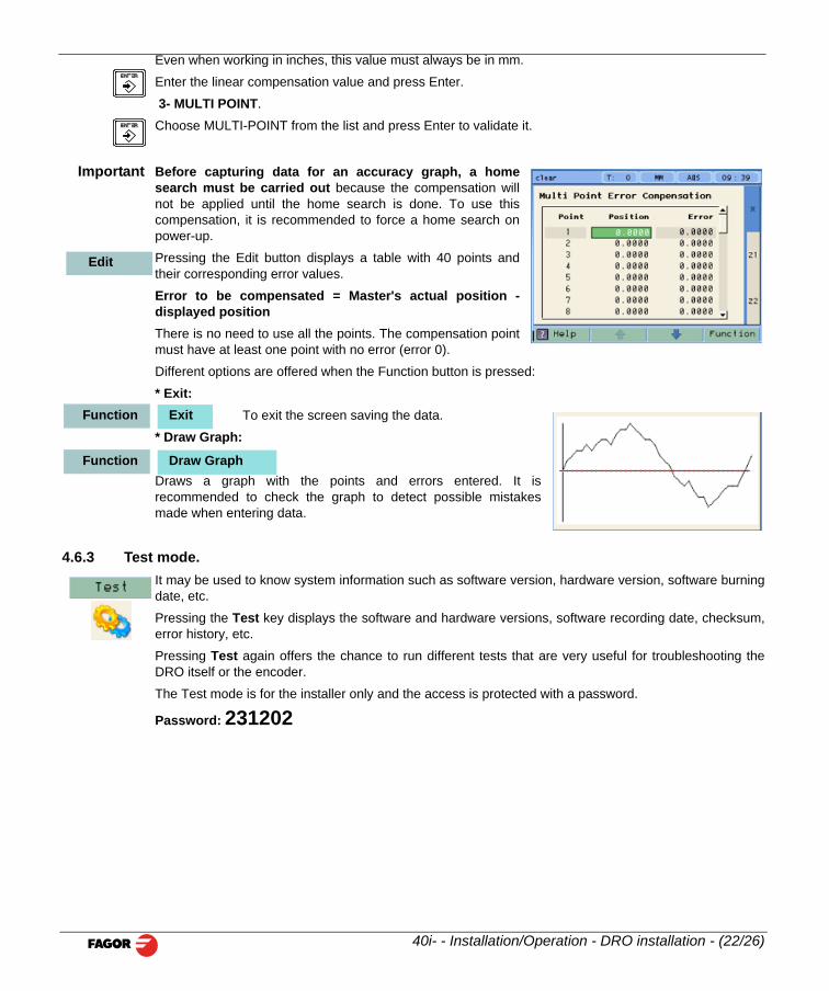
3- MULTI POINT.
Choose MULTI-POINT from the list and press Enter to validate it.
Important Before capturing data for an accuracy graph, a homesearch must be carried out because the compensation willnot be applied until the home search is done. To use thiscompensation, it is recommended to force a home search onpower-up.
Pressing the Edit button displays a table with 40 points andtheir corresponding error values.
Error to be compensated = Master's actual position -displayed positionThere is no need to use all the points. The compensation pointmust have at least one point with no error (error 0).
Different options are offered when the Function button is pressed:
* Exit: To exit the screen saving the data.
* Draw Graph:
Draws a graph with the points and errors entered. It isrecommended to check the graph to detect possible mistakesmade when entering data.
4.6.3 Test mode.It may be used to know system information such as software version, hardware version, software burningdate, etc.
Pressing the Test key displays the software and hardware versions, software recording date, checksum,error history, etc.
Pressing Test again offers the chance to run different tests that are very useful for troubleshooting theDRO itself or the encoder.
The Test mode is for the installer only and the access is protected with a password.
Edit
ExitFunction
Draw GraphFunction
40i- - Installation/Operation - DRO installation - (22/26)
Password: 231202

5 Appendix
5.1 UL seal see "Rear panel" (page 16).
5.2 CE seal
WarningBefore starting up the DRO, carefully read the instructions of Chapter 2 in this manual.The DRO must not be powered-on until verifying that the machine complies with the "89/392/CEE" Directive.
5.2.1 Declaration of conformityManufacturer: Fagor Automation, S. Coop.
Barrio de San Andrés 19, C.P. 20500, Mondragón -Guipúzcoa (ESPAÑA)
We hereby declare, under our responsibility that the product:
Fagor Digital Readout: 40i, 40i-B
meets the following directives:
SAFETY EN 60204-1Machine safety. Electrical equipment of the machines
ELECTROMAGNETIC COMPATIBILITY:EN 61000-6-4Emission, EN 55011Radiated. Class A, Group 1, EN 55011Conducted. Class A, Group 1,EN 61000-3-2Harmonics, EN 61000-3-3Flickers, EN 61000-6-2Immunity, EN 61000-4-2Electrostaticdischarges, EN 61000-4-3Electromagnetic fields radiated in radiofrequency, EN 61000-4-4Rapidtransients and blasts, EN 61000-4-5Shockwaves, EN 61000-4-6Disturbances conducted by fields inradiofrequency, EN 61000-4-8Magnetic fields at mains frequency, EN 61000-4-11Voltage variations andoutages, ENV 50204 Electromagnetic fields irradiated by radio telephones.
As instructed by the European Community Directives on Low Voltage: 73/23/EEC, (and the 93/68/EECamendment) on Machine Safety 89/392/EEC and 89/336/EEC on Electromagnetic Compatibility.
In Mondragón, April 1st, 2005
40i - Installation/Operation - Appendix - (23/26)
5.2.2 Safety conditionsRead the following safety measures in order to prevent damage to personnel, to this product and to thoseproducts connected to it.
Fagor Automation shall not be held responsible for any physical or material damage derived from theviolation of these basic safety regulations.
Do not manipulate the inside of the unitOnly personnel authorized by Fagor Automation may manipulate the inside of this unit.
Do not handle the connectors while the unit is under power. Before handling the connectors (mains, feedback, etc.) make sure that the unit is not under power.
Use proper Mains AC power cables.To avoid risks, use only the Mains AC cables recommended for this unit.
Avoid electrical overloadsIn order to avoid electrical discharges and fire hazards, do not apply electrical voltage outside the rangeindicated in chapter 2 of this manual
Ground connectionIn order to avoid electrical discharges, connect the ground terminals of all the modules to the main groundterminal. Before connecting the inputs and outputs of this unit, make sure that all the groundingconnections are properly made.
Before powering the unit up, make sure that it is connected to groundIn order to avoid electrical discharges, make sure that all the grounding connections are properly made.
Ambient conditionsRespect the limits for temperature and relative humidity indicated in chapter
Do not work in explosive environmentsIn order to avoid risks, damage, do not work in explosive environments.
Work environmentThis unit is ready to be used in Industrial Environments complying with the directives and regulationseffective in the European Community.
Install this DRO vertically so its power switch of the back panel is at a distance between 0.7 m (27.5inches) and 1.7 m (5.6 ft) off the floor and away from coolants, chemical products, blows etc that coulddamage it. Keep it away from direct sunlight, extremely hot air, high voltage and high current sources aswell as from relays, or high electromagnetic fields (about 0.5 m or 20 inches).
40i - Installation/Operation - Appendix - (24/26)
This unit complies with the European directives on electromagnetic compatibility. Nevertheless, it isrecommended to keep it away from sources of electromagnetic disturbance such as.
- Powerful loads connected to the same AC power line as this equipment.
-Nearby portable transmitters (Radio-telephones, Ham radio transmitters).
-Nearby radio / TC transmitters.
-Nearby arc welding machines.
-Nearby High Voltage power lines.
-Disturbance generating elements of the machine.
-Etc.
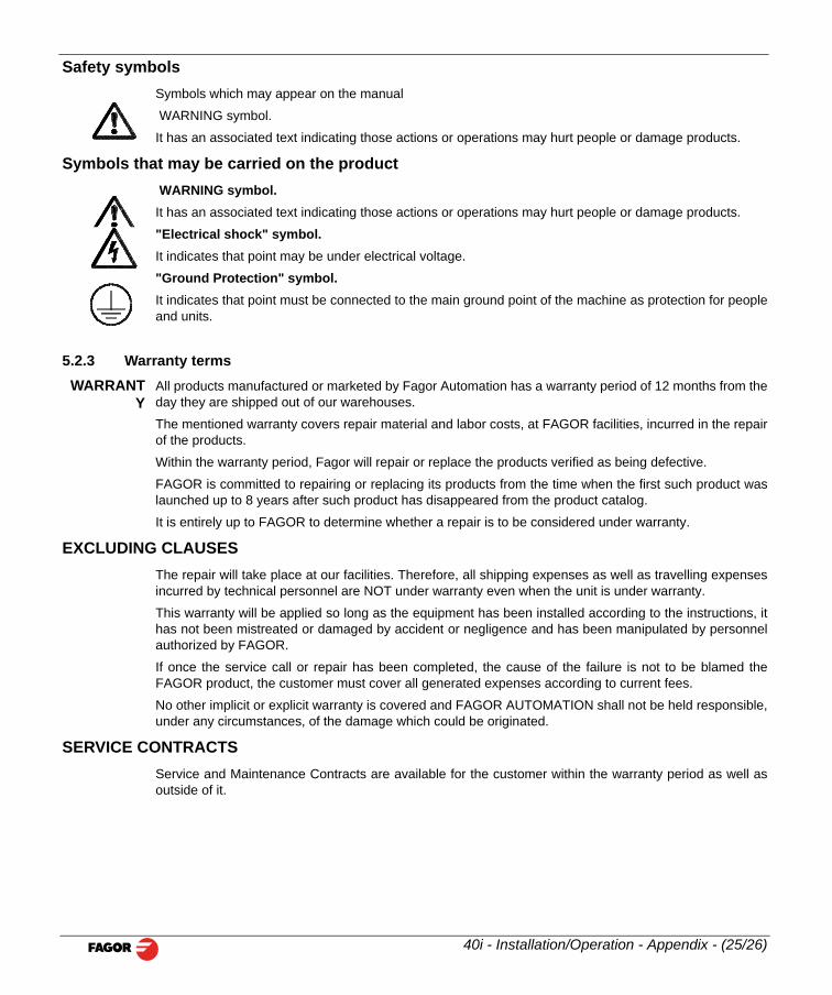
Safety symbolsSymbols which may appear on the manual
WARNING symbol.
It has an associated text indicating those actions or operations may hurt people or damage products.
Symbols that may be carried on the product WARNING symbol. It has an associated text indicating those actions or operations may hurt people or damage products.
"Electrical shock" symbol.It indicates that point may be under electrical voltage.
"Ground Protection" symbol.It indicates that point must be connected to the main ground point of the machine as protection for peopleand units.
5.2.3 Warranty termsWARRANT
YAll products manufactured or marketed by Fagor Automation has a warranty period of 12 months from theday they are shipped out of our warehouses.
The mentioned warranty covers repair material and labor costs, at FAGOR facilities, incurred in the repairof the products.
Within the warranty period, Fagor will repair or replace the products verified as being defective.
FAGOR is committed to repairing or replacing its products from the time when the first such product waslaunched up to 8 years after such product has disappeared from the product catalog.
It is entirely up to FAGOR to determine whether a repair is to be considered under warranty.
EXCLUDING CLAUSESThe repair will take place at our facilities. Therefore, all shipping expenses as well as travelling expensesincurred by technical personnel are NOT under warranty even when the unit is under warranty.
This warranty will be applied so long as the equipment has been installed according to the instructions, ithas not been mistreated or damaged by accident or negligence and has been manipulated by personnelauthorized by FAGOR.
If once the service call or repair has been completed, the cause of the failure is not to be blamed theFAGOR product, the customer must cover all generated expenses according to current fees.
No other implicit or explicit warranty is covered and FAGOR AUTOMATION shall not be held responsible,
40i - Installation/Operation - Appendix - (25/26)
under any circumstances, of the damage which could be originated.
SERVICE CONTRACTSService and Maintenance Contracts are available for the customer within the warranty period as well asoutside of it.
5.2.4 Material returning termsWhen returning the DRO, pack it in its original package and with its original packaging material. If notavailable, pack it as follows:
Get a cardboard box whose three inside dimensions are at least 15 cm (6 inches) larger than those of theunit. The cardboard being used to make the box must have a resistance of 170 Kg (375 lb.).
When sending it to a Fagor Automation office for repair, attach a label indicating the owner of the unit,person to contact, type of unit, serial number, symptom and a brief description of the problem.
Wrap the unit in a polyethylene roll or similar material to protect it.
Pad the unit inside the cardboard box with polyurethane foam on all sides.
Seal the cardboard box with packing tape or industrial staples.
MaintenanceCleaning: An accumulation of dirt in the equipment can act as a screen preventing proper dissipation of the heat
generated by the internal electronic circuits with the consequent danger of overheating and DRO fault.
Accumulated dirt can also, in some cases, provide a conductive path for electricity which could give rise tofaults in the internal circuits of the equipment, especially in high humidity conditions.
To clean the equipment nonabrasive dish-washing detergents are recommended (in liquid, never powderform) or 75% isotropic alcohol with a clean cloth. DO NOT USE aggressive solvents, (benzol, acetones,etc.) which could damage the materials the equipment is made with.
Do not use high pressure compressed air to clean the item as this could give rise to an accumulation ofcharges which in turn lead to electrostatic discharges.
The plastics used in the front panel of the DRO stand up to: Grease and mineral oil, alkalis and bleaches,dissolved detergents and alcohol.
Avoid the effect of solvents such as Chlorohydrocarbons, Benzol, Esters and Ethers because these coulddamage the plastics with which the front of the equipment is made.
Preventive InspectionIf the DRO does not come on press the rear switch for starting, make sure it is properly connected andbeing supplied with the proper mains voltage.
FAGOR AUTOMATION S. COOP.
Bª San Andrés Nº 19
Apdo de correos 144
20500 Arrasate/Mondragón
Web: www.fagorautomation.com
Email: [email protected]
Tel.: (34) 943 719200
Fax: (34) 943 791712
40i - Installation/Operation - Appendix - (26/26)
Fagor shall not be held responsible for any printing or transcribing errors in this manual and reserves theright to make any modifications to the characteristics of their products without prior notice.
- Spain -