innova 40i ts dro manual - fagor · pdf file40i ts - v1205 - installation/operation - (3/29) 1...
TRANSCRIPT

Innova 40i TS / 40i TS-BInstallation / Operation Manual
Manual version: 1205Software version: 2.00
Manual code: 14460114

INDEX
1 DRO description ........................................................................................ 31.1 Front plate: ....................................................................................................................... 31.2 Turning the unit on and off ............................................................................................. 31.3 Main screen description: ................................................................................................ 41.4 Function bar..................................................................................................................... 41.4.1 Access to functions: .........................................................................................................................4
2 DRO operation ........................................................................................... 52.1 Display modes. ................................................................................................................ 52.1.1 mm / inch .........................................................................................................................................52.1.2 rad/diam ...........................................................................................................................................52.1.3 inc / abs ...........................................................................................................................................52.1.3.1 Absolute mode: ................................................................................................................................52.1.3.2 Incremental mode: ...........................................................................................................................52.2 Set/Clear ........................................................................................................................... 62.2.1 In "Set" mode (indicated with an "S" on the upper status bar) .........................................................62.2.2 In "Clear" mode (indicated with a "C" on the upper status bar) .......................................................62.3 Machine reference (home) search ................................................................................. 62.4 Tool:.................................................................................................................................. 62.4.0.1 Tool setting: .....................................................................................................................................72.4.0.2 Setting the tool by touching a part of known diameter: ....................................................................72.4.0.3 Setting the tool by touching a part of unknown diameter: ................................................................72.4.1 View tool table: .................................................................................................................................72.5 Machine control ............................................................................................................... 82.5.1 Spindle Control ................................................................................................................................82.5.1.1 Potentiometer Control ......................................................................................................................82.5.2 Range (gear) change. ......................................................................................................................82.5.3 Control of maximum spindle speed ..................................................................................................92.5.4 Spindle orientation ...........................................................................................................................92.5.5 Emergency input ..............................................................................................................................92.6 Special functions. ............................................................................................................ 92.6.1 Set RPM .........................................................................................................................................102.6.2 Set Constant Surface Speed, CSS ................................................................................................102.6.3 Angle measurement. ......................................................................................................................102.6.4 Turning function. ............................................................................................................................112.6.5 Calculator function. ........................................................................................................................11
3 DRO installation ...................................................................................... 123.1 Mounting on the support arm....................................................................................... 123.2 Mounting of the built-in model. .................................................................................... 123.3 Rear panel ...................................................................................................................... 133.4 General technical characteristics ................................................................................ 143.5 Connections................................................................................................................... 143.5.1 Connection of the feedback systems .............................................................................................143.5.2 Input/output connection 37-pin connector ......................................................................................153.5.2.1 Connection diagram .......................................................................................................................163.5.2.2 Connection example ......................................................................................................................163.5.3 Power and machine connection .....................................................................................................17
40i TS - v1205 - Installation/Operation - (1/29)

3.6 Installation parameters ................................................................................................. 173.6.1 Accessing installation parameters .................................................................................................173.6.2 User parameters: ...........................................................................................................................173.6.2.1 Language .......................................................................................................................................173.6.2.2 Screen color ...................................................................................................................................173.6.3 Installer parameters .......................................................................................................................183.6.3.1 Parameter backup into USB memory ............................................................................................183.6.3.2 DRO: ..............................................................................................................................................183.6.3.3 Feedback: ......................................................................................................................................203.6.3.4 Compensation: ...............................................................................................................................213.6.4 Test mode. .....................................................................................................................................223.6.5 Machine Control .............................................................................................................................223.6.5.1 Spindle Configuration .....................................................................................................................233.6.5.2 Spindle orientation .........................................................................................................................233.6.5.3 Range configuration .......................................................................................................................243.6.5.4 RPM table for each range ..............................................................................................................243.6.5.5 Gear (range) detection inputs ........................................................................................................243.6.5.6 Active level configuration ...............................................................................................................253.6.5.7 External device or box for speed limitation ....................................................................................25
4 Appendix .................................................................................................. 264.1 UL seal............................................................................................................................ 264.2 CE seal............................................................................................................................ 264.2.1 Declaration of conformity ...............................................................................................................264.2.1.1 Electromagnetic compatibility: .......................................................................................................264.2.2 Safety conditions ............................................................................................................................264.2.3 Warranty terms ..............................................................................................................................284.2.4 Material returning terms .................................................................................................................28
IMPORTANT NOTE
Some of the features described in this manual may not beavailable in this version.
Consult with the Fagor Automation branch office nearest you.
40i TS - v1205 - Installation/Operation - (2/29)

1 DRO description
1.1 Front plate:
1.2 Turning the unit on and offIt turns on automatically when applying voltage or after pressing the on/off key.
On power-up, an initial screen comes up for a few seconds and then the work screen is displayed.
Turns the DRO on or off.
Keys for entering numeric values
Power-off button
Cursor keys
Keys for axes
Validate
Abort
Power indicator LED
Keys to open droplist buttons of theFUNCTION BAR
TFT screen
Spindle keys
40i TS - v1205 - Installation/Operation - (3/29)

t
1.3 Main screen description:
When the spindle is off, the RPM and CSS displays show the programmed values.
When the spindle is ON and there is an encoder on the spindle, the RPM and CSS displays will showthe current value; but if there is no encoder, they will show their theoretical values.
1.4 Function barThe function bar gives access to the various functions offered by the DRO.
1.4.1 Access to functions:
Active tool Nr.
Display units mm/inch Display mode: INC/ABS
Set/Clear Chronometer
DISPLAY AREA
STATUS BAR
FUNCTION BAR
Current tool Current/programmed RPM Current/programmed CSS CSS mode ON
Spindle orientation
Current range
TOOL
Set tool Nr.
Teach-in Tool table
DISPLAY
Set/Clear
inc/abs
mm/inch
FUNCTION
Home search
Setup
Setup
RPM
Angle measuremen
Calculator
CSS
Turning
rad/diam
40i TS - v1205 - Installation/Operation - (4/29)

2 DRO operation
2.1 Display modes. Toggle the reading of the second axis between Z (Z1 + Z2), Z1 or Z2, when the DRO has been set for3-axis lathe.
2.1.1 mm / inch
Toggle units between mm and inches.
This toggle is possible if the installer parameters have been set as toggle .
2.1.2 rad/diam
Toggle between radius mode and diameter mode. It only affects the X axis.
In diameter mode, the X axis display shows twice the actual distance traveled by the tool. When this
mode is active, the X axis display shows the sign.
In radius mode, the X axis display shows the actual distance traveled.
2.1.3 inc / abs
ñ
Toggle between incremental and absolute feedback reading (counting). The status bar shows thecurrently active mode.
2.1.3.1 Absolute mode:
In this mode, the coordinates (position values) arereferred to part zero.
Example on the right:
Set the DRO in absolute mode.
Set part zero (datum).
Run several passes moving the Z axis from “0“ to “63.6”until obtaining the desired diameter.
Run several passes moving the Z axis from “0“ to “47.6”until obtaining the desired diameter.
Run several passes moving the Z axis from “0“ to “22.6”until obtaining the desired diameter.
2.1.3.2 Incremental mode:
The coordinate is referred to the previous point where theaxis display has been set to zero.
Set the dro in incremental mode.
Set a floating zero (Z=0) at point A.
Preset the value “22.6” for the Z axis. Run several passesmoving the Z axis from “0“ to “63.6” until obtaining thedesired diameter.
Clear Z axis.
Preset the value “25” for the Z axis. Run several passesmoving the Z axis from “0“ to “63.6” until obtaining thedesired diameter.
Clear Z axis.
Preset the value “15” for the Z axis. Run several passes moving the Z axis from “0“ to “63.6” untilobtaining the desired diameter.
3rd
Display mm/inch
Display rad/diam
Display inc/abs
ABSOLUTE MODE
A
INCREMENTAL MODE
A
40i TS - v1205 - Installation/Operation - (5/29)
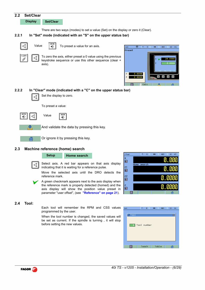
2.2 Set/Clear
There are two ways (modes) to set a value (Set) on the display or zero it (Clear).
2.2.1 In "Set" mode (indicated with an "S" on the upper status bar)
To preset a value for an axis.
To zero the axis, either preset a 0 value using the previouskeystroke sequence or use this other sequence (clear +axis).
2.2.2 In "Clear" mode (indicated with a "C" on the upper status bar)
Set the display to zero.
To preset a value:
And validate the data by pressing this key.
Or ignore it by pressing this key.
2.3 Machine reference (home) search
Select axis. A red bar appears on that axis displayindicating that it is waiting for a reference pulse.
Move the selected axis until the DRO detects thereference mark.
A green checkmark appears next to the axis display whenthe reference mark is properly detected (homed) and theaxis display will show the position value preset inparameter "user offset", (see "Reference" on page 21).
2.4 Tool:Each tool will remember the RPM and CSS valuesprogrammed by the user.
When the tool number is changed, the saved values willbe set as current. If the spindle is turning , it will stopbefore setting the new values.
Display Set/Clear
Value
Value
Setup Home search
40i TS - v1205 - Installation/Operation - (6/29)

2.4.0.1 Tool setting:
When going into Teach mode, if the DRO was in INC mode, it switches to ABS mode.
2.4.0.2 Setting the tool by touching a part of known diameter:
Enter tool number. Press Enter.
Move the X axis until the tool touches the part. Preset thepart diameter.
Move the Z axis until the tool touches the part. Preset thevalue for the Z axis.
Press button to validate.
2.4.0.3 Setting the tool by touching a part of unknown diameter:
When the part must be removed to measure its dimensions, use the HOLD function.
Enter tool number. Press Enter.
Move the X axis until the tool touches the part.
Move the Z axis until the tool touches the part.
Press HOLD for both axes.
Remove the part and measure it.
Preset the X axis with the measured diameter value.
Preset the value for the Z axis.
Press button to validate.
These tool presets are kept in memory even when the unit is powered off up to a maximum of 10years.
Notes: The presets done with any tool in incremental mode change the part zero for all the tools.
If a tool offset has been preset in Z1, Z2 or Z (Z1 + Z2) mode, that tool must be used in the same
mode (Z1, Z2 or Z) when using it to machine the part.
The tool offsets are referred to the machine zero found at the time. When turning the DRO on, it isnecessary to find the same reference mark.
2.4.1 View tool table:
View tool offset table.
Teach
Hold
Tool Table
40i TS - v1205 - Installation/Operation - (7/29)

2.5 Machine control
This unit offers the possibility to control the spindle as well as the inputs and outputs required for it.
2.5.1 Spindle Control
The Start Stop keys control the machine spindle.
Start spindle in m3.
Start spindle in m4.
Stop the spindle.
Note:
If the spindle is already turning, the m3 and m4 keys will speed up or slow down the spindle.
When starting or stopping the spindle, the machine will follow the programmed acceleration time.
The external JOG keys, M3 and M4, will work in the same way as the DRO keys.
2.5.1.1 Potentiometer Control
The spindle speed can be changed manually using an external potentiometer.
The potentiometer mode will turn on when the digital input called “Potentiometer on/off” is activated(the icon indicates that the potentiometer mode is active). Then, the analog input will be assumed asspindle velocity command. When exiting the potentiometer mode by deactivating the digital input“Potentiometer on/off” and after stopping the spindle, the DRO will return to its previous state, eitherRPM mode or CSS mode.
2.5.2 Range (gear) change.
When selecting a work range other than the current one,the DRO waits for the user to change to the indicatedrange (gear).
When using automatic range (gear) detection, the rangecannot be edited at the DRO, just change the range andaccept the confirmation of the change at the DRO.
The current range value will be read through inputs DM41,DM42, DM43, DM44. The exact combination of inputsDM41...DM44 for each range may be set by parameter.
If it detects that the gear has been changed whilemachining, the spindle stops immediately and it cannot berestarted until the range change is confirmed at the DRO.
The DRO generates digital outputs in order to be able use an automatic gear change.
Outputs M41, M42, M43 and M44 indicate the range (gear) to change to (M41 indicates Gear 1, M42indicates Gear 2, etc.), then, the STROBE signal to command the gear changer to act. It is alsopossible to wait for the “M-done” signal as confirmation for the DRO that the gear change process iscompleted successfully.
M-done
M41...M44
STROBE
40i TS - v1205 - Installation/Operation - (8/29)

2.5.3 Control of maximum spindle speed
Maximum spindle speed may be limited by an external device connected to inputs DT1, DT2, DT3and DT4. A rotary selector switch may be used, binary, bcd, gray, etc. Or an intelligent device forsafety.
It is possible to edit the RPM values for each combination of inputs DT1 to DT4.
The speed indicated by these inputs will be assumed as the maximum allowed at all times, even inpotentiometer mode.
2.5.4 Spindle orientation
For stopping the spindle in an angular position set by theuser. It requires an encoder on the spindle.
How to preset the spindle orientation point.
While the spindle is stopped, access the following screen.
Turn spindle orientation off
Turn spindle orientation on
It takes the value of the current spindle position as the preset position to stop the spindle.
The icon shows that the spindle orientation mode is ON.
How to orient the spindle
While in spindle orientation mode, it will stop at the position preset earlier.
Force a stop.
Pressing STOP twice aborts spindle orientation and the spindle stops.
2.5.5 Emergency input
The emergency input will stop the spindle immediately and disable all the digital outputs.
2.6 Special functions.
It gives access to the specific lathe functions.
OFF
ON
Function
40i TS - v1205 - Installation/Operation - (9/29)

2.6.1 Set RPM
For setting the RPM value for the current tool.
RPM: Desired value in revolutions per minute
Range: Gear range position
Validate the programmed values
Exit without changing values
Note:
The preset value must be between the minimum and the maximum rpm for the selected range (gear).
Setting the RPM value turns the CSS mode OFF.
2.6.2 Set Constant Surface Speed, CSS
For setting the Constant Surface Speed value for thecurrent tool.
CSS: Constant surface speed in m/min or ft/min.
Max RPM: Maximum working RPM value
Range:Gear range position
Disable the CSS mode
Validate the programmed values
Exit without changing values
Note:
When CSS mode is ON, the CSS display of the main window will show a yellow light.
If the X axis value is changed by clearing it or by presetting a new value, the spindle will stop forsafety.
2.6.3 Angle measurement.
It may be used to calculate the angle or taper of a part bytouching two points.
Touch the first point and press Enter.
Touch the second point and press Enter.
It shows the calculated angle in degrees and degrees -minutes - seconds.
Function RPM
Function CSS
Function Angle measurement
40i TS - v1205 - Installation/Operation - (10/29)

2.6.4 Turning function.
Assistant for defining a turning cycle after having enteredthe following data:
X: Starting diameter. Move the X axis until the tooltouches the part. Press X axis button to enter the positionvalue on the X axis. If the part diameter is known, its valuemay be entered directly. Press Enter. The next field (box)is activated.
Z: Initial Z axis value. Place the tool touching the part onthe Z axis. Preset a value and press the button for the Zaxis to enter the value of the Z axis display. Press Enter.The next field (box) is activated.
X: Enter final diameter. Press Enter.
Z: Enter Z axis final value. Press Enter. Press Enter.
Cut: Enter cutting pass in mm. The DRO will use this value also as the safety distance to withdrawafter each pass.
Execute turning cycle. Move the axes until both axis displays read zero.
Go on to the next execution step.
2.6.5 Calculator function.
It may be used to carry out mathematical andtrigonometric operations as well as preset the desired axiswith the result of the calculation or import the displayedcoordinate values into the calculator to carry out mathoperations.
Different types of calculators may be selected at thefunction bar: Arithmetic, trigonometric and for squarefunctions.
Numeric calculator. Functions: + - x /
Trigonometric calculator. Functions: Sin, Cos, Tan.
Functions:
To Exit the calculator Set an axis with the result or Insert a value into the calculator.
Exit the calculator.
Set one of the axis with the result of the calculator. To do this, access the calculator
by pressing the Calc button of the function bar on the Preset screen.
Enter the value of an axis, PI or 2PI into the calculator.
Function Turning
Run
Current step Nr.
Total number of steps.
Function Calculator
Numeric
Trigonom
Square
Function
Exit
Set
Insert
40i TS - v1205 - Installation/Operation - (11/29)

3 DRO installation
There are two ways to mount the Innova 40i TS:
1- Mounted on the support arm.
2- Built-in model.
3.1 Mounting on the support arm.The DRO may be mounted at the desired height and may be oriented at will.
The DRO is mounted on to the support arm using two set-screws.
3.2 Mounting of the built-in model.The DRO is ready to be built into an operator panel or pendant. The name of this model is special, aB has been added at the end of the product name.
Example: INNOVA 40i TS-B
Dimensions of the DRO and the window to insert it into.The first figure shows the DRO dimensions. The second figure shows the dimensions of the holeneeded in the enclosure of the machine to built this model into.
On support arm Built-in
40i TS - v1205 - Installation/Operation - (12/29)

3.3 Rear panelOn the back of the unit the following items may be found:
* Three-prong power connector for AC and ground connection.
* M6 mm terminal, for general machine ground connection.
* Mounting bracket.
* Feedback connectors:
X1.-SUB-D HD type 15-pin female connector for 1st axis feedback device.
X2.-SUB-D HD type 15-pin female connector for 2nd axis feedback device.
X3.-SUB-D HD type 15-pin female connector for the third axis feedback device.
X4.-SUB-D HD type 15-pin female connector for 4th axis (spindle) feedback device.
* 37-pin connector for inputs and outputs.
*USB connector.
In order to comply with UL standards, this unit must be connected in the final application using alisted detachable cord set (BLEZ) with a molded three-prong plug and a suitable fitting to beconnected to the equipment, rated minimum 300 V AC. The cord type shall be SO, SJO or STO.Suitable Strain Relief means must be provided in the cord set to assure the connection of the plugand the fitting.
ETL file number:
WARNINGDo not handle the connectors while the unit is under power.
Before handling the connectors (mains, feedback, etc.) make sure that the unit is not under power.
It is NOT enough to turn the display off by using the [on/off] key at the keyboard
ULseal
40i TS - v1205 - Installation/Operation - (13/29)

3.4 General technical characteristicsUniversal Power Supply between 100V AC and 240V AC ±10% at mains frequency between 45 Hzand 400 Hz between 120V DC and 300 V DC. It withstands power outages of up to 20 milliseconds.
-10-year memory backup of installation parameters when the unit is off.
-The operating temperature inside the DRO enclosure must be between 5º C and 45º C (41ºF and113ºF).
-The storage temperature inside the DRO enclosure must be -25º C and +70º C (-13º F and 158º F).
-Maximum relative humidity: 95% non condensing at 45ºC (113ºF).
-Front Panel Sealing: IP54 (DIN 40050), Rear panel: IP4X (DIN40050) except for built-in models inwhich case is: IP20.
3.5 Connections3.5.1 Connection of the feedback systems
The feedback systems (linear or rotary encoders) are connected via SUB-D HD type 15-pin femaleconnectors: X1 through X4.
Characteristics of feedback inputs: X1, X2, X3 and X4:-Maximum feedback consumption: 250 mA at the +5V input.
-Admits square-wave signal (TTL).
-It admits voltage modulated 1 Vpp sinusoidal signal.
-It admits SSI communication for absolute encoders.
-Maximum frequency: 750 kHz
-Phase shift: 90º ±20º, hysteresis: 0.25 V, Vmax: 7V, maximum input current: 3mA
- High threshold (logic state 1): 2.4 V < VIH< 5 V
- Low threshold (logic state 0): 0.0 V < VIL< 0.55 V
Feedback connection. Connectors X1, X2, X3 and X4
PinSignal1Vpp/TTL
SignalSSI
Function
1 A -
Input for feedback signals
2 /A -
3 B -
4 /B -
5 I0 Data
6 /I0 /Data
7 Alarm Clock
8 /Alarm* /Clock
9 +5V Power supply to feedback devices
10 Not connected
11 0V Power supply to feedback devices
12, 13, 14 Not connected
15 Chassis Shield
1
40i TS - v1205 - Installation/Operation - (14/29)

3.5.2 Input/output connection 37-pin connector
Characteristics of the analog input:
Voltage range: ±10V
Impedance > 10 kOhm
Maximum unshielded cable length: 75mm
Characteristics of the analog output:
Voltage range: ±10V
Minimum impedance of the input to which it is connected: 10 kOhm
Maximum unshielded cable length: 75mm
We recommend using shielded cables joining the shield to the connector housing at each end.
Characteristics of the digital inputs:
Rated voltage: +24 V DC
Maximum voltage: +30 V DC
Minimum voltage: +18V DC
High threshold voltage (logic state 1): > +18V.
Low threshold voltage (logic state 0): < +5V
Typical consumption of each input: 5mA
Maximum consumption of each input: 7mA
Characteristics of the digital outputs:
Rated voltage: 24 V AC or DC
Maximum voltage: 47 V AC or DC.Protection against over-voltage
Maximum load current: 100mA Protection against over-current
Activation time: <3ms
Deactivation time: <3ms
PIN I/O Signal PIN I/O Signal1 Chassis2 I 0V external 20 I 0V external3 I 24V external 21 I 24V external4 S 24V user 22 S 24V user5 S M3 23 I Jog [+]6 S M41 24 S M47 S M43 25 S M428 I Jog [-] 26 S M449 S 27 S M STROBE
10 S 28 S11 I Detect MAX RPM 1 29 S12 I Detect MAX RPM 3 30 I Detect MAX RPM 213 I Emergency 31 I Detect MAX RPM414 I Jog - M3 32 I M-done15 I Detect M41 33 I Jog - M416 I Detect M43 34 I Detect M4217 Chassis 35 I Detect M4418 I Analog potentiometer 36 I Potentiometer
On/Off19 I/O 0V analog 37 S Spindle command
40i TS - v1205 - Installation/Operation - (15/29)

3.5.2.1 Connection diagram
3.5.2.2 Connection example
+24V +24V
R=1KRelay
Out 1
To a digital input
Out 2 Out 4 Out n 0V external
SPINDLE
GEARBOX
RANGECONTROL
MOTORCONTROL
LIMITRPM
EXTERNAL
ANALOG. SPINDLEANALOG. GND
POT. ANALOG.
POTENTIOMETER SWITCH
EMERGENCY
DIGITALGND
24 V
US
ER
PO
TE
NT
IOM
ET
ER
ENCODER
INNOVA 40i TS
40i TS - v1205 - Installation/Operation - (16/29)

3.5.3 Power and machine connection
Always mount it vertically so its keyboard is within operator's reach and its digits are easily visible (atoperator's eye level).
Do not connect or disconnect the DRO connectors while it is under power.
Connect all metallic parts to a common point on the machine tool and it to the general ground point.
Use cables of enough gage (no thinner than 8 mm 2 ) for this connection.
3.6 Installation parameters
3.6.1 Accessing installation parameters
Gives access to setting installation and user parametersand to the test mode.
The parameter setup is divided into three parts:
1- USER PARAMETERS: Parameters that may bemodified by the user: change the language, set the clockand set the screen color.
2- INSTALLER PARAMETERS: Parameters that must beset when installing the DRO for the first time, whenreplacing an encoder or when doing a repair. They areparameters related to the machine, feedback and to theDRO itself.
3- TEST MODE: To check the various status of different elements of the DRO, such as screen,keyboard, etc.
For the installer only. Accessing the test mode requires a password:
Password: 231202
3.6.2 User parameters:
Parameters that may be modified by the user: change the language, set the clock and set the screencolor.
3.6.2.1 Language
Use the cursor keys to select the language.
Press Enter.
Home search Setup
Setup
Test InstallerUser
ColorLanguagePassword231202
DRO(type, axes, alarms)
Feedback(encoders)
Compensation(linear, multi-point)
Machine Control
SetupSetup
User
Install
Test
SetupSetup User
40i TS - v1205 - Installation/Operation - (17/29)

3.6.2.2 Screen color
Use the cursor keys to change the colors for the background, for the numbers, for the box, etc.
The default box shows the three preset options:
1- Default: Blue background with yellow numbers.
2- Color 1: Black background with yellow numbers.
3- Color 2: Green background, white box and green numbers.
3.6.3 Installer parameters
Parameters that must be set when installing the DRO for the firsttime, when replacing an encoder or when doing a repair. They areparameters related to the machine, feedback and to the DROitself.
Enter the password: 231202This window offers the following options:
DRO, feedback, error compensation and machinecontrol.
3.6.3.1 Parameter backup into USB memory
If a USB memory is connected, it is possible to save and recover:
- DRO parameters
- Multi-point compensdation tables
- User programs
3.6.3.2 DRO:
It configures the DRO for each type of machine: Numberof axes, default units, etc.
Pressing this button opens the window shown on the right.The following items are set in it:
1- Type of machine: In this case, it is set for lathe.
2- Number of axes to display: 1, 2 or 3.
This model sets 4 axes. The fourth one is the spindle.
3- Default units: mm or inches.
4- Toggled by the user: Yes or NO. If set to "YES", tochange the units, select the mm/inch option from theDisplay drop list while the DRO is showing the main screen.
ColorSet
SetupSetup Installer parameters
Setup DROInstaller parametersSetup
40i TS - v1205 - Installation/Operation - (18/29)

Axes option:
These parameters must be set for each axis.
Note: To select the spindle axis (the 4th axis), press the 3rd axis key twice.
1- Combine axes: It is possible to add/subtract any axisto/from another axis. The factory setting is NO.
Rotary axes cannot be combined.
2- Display resolution: It is the resolution of the DRO. Itmakes it possible to display the position with a coarserresolution than that of the feedback device, although theactual internal calculation is done with the finestresolution.
Factory setting: 0.0000. It means that the displayresolution is the encoder resolution.
3- Reverse the feedback reading (pulse counting)direction: Yes or NO. Factory setting: NO.
4- Display feedrate: Axis feed rate, both in mill and lathe modes. When activating this option("YES"), the screens shows a window indicating the feed rate of each axis.
5- Default value: Measurement in radius or diameter. Only available for the X axis.
The units will be m/min or inches/min depending on whether MM or INCH is active.
Alarms option:
Turn on/off the various types of alarms.
These alarms must be set for each axis. The followingscreen is displayed:
1- 1 Vpp alarm: The DRO checks the amplitude andphase shift of 1 Vpp signals. An alarm is displayed whenany of the signals gets out of the set limits.
2- Feedback alarm: Feedback alarm provided by TTLangular encoders. It may be active low (TTL 0) or activehigh (TTL 1).
3- Feed rate overrun alarm: When set to YES, an alarmis issued over 200 kHz.
4- Travel limits: Setting it to YES activates two more fields (boxes) for entering the travel limits. Awarning appears on the screen when overrunning these limits.
Setup DRO AxesInstaller parametersSetup
Setup DRO AlarmsInstaller parametersSetup
40i TS - v1205 - Installation/Operation - (19/29)
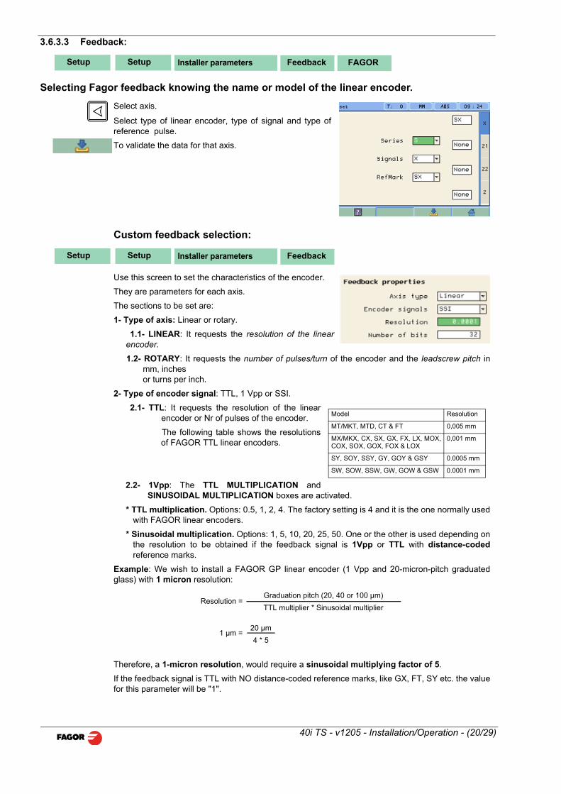
3.6.3.3 Feedback:
Selecting Fagor feedback knowing the name or model of the linear encoder.
Select axis.
Select type of linear encoder, type of signal and type ofreference pulse.
To validate the data for that axis.
Custom feedback selection:
Use this screen to set the characteristics of the encoder.
They are parameters for each axis.
The sections to be set are:
1- Type of axis: Linear or rotary.
1.1- LINEAR: It requests the resolution of the linearencoder.
1.2- ROTARY: It requests the number of pulses/turn of the encoder and the leadscrew pitch inmm, inches or turns per inch.
2- Type of encoder signal: TTL, 1 Vpp or SSI.
2.1- TTL: It requests the resolution of the linearencoder or Nr of pulses of the encoder.
The following table shows the resolutionsof FAGOR TTL linear encoders.
2.2- 1Vpp: The TTL MULTIPLICATION andSINUSOIDAL MULTIPLICATION boxes are activated.
* TTL multiplication. Options: 0.5, 1, 2, 4. The factory setting is 4 and it is the one normally usedwith FAGOR linear encoders.
* Sinusoidal multiplication. Options: 1, 5, 10, 20, 25, 50. One or the other is used depending onthe resolution to be obtained if the feedback signal is 1Vpp or TTL with distance-codedreference marks.
Example: We wish to install a FAGOR GP linear encoder (1 Vpp and 20-micron-pitch graduatedglass) with 1 micron resolution:
Therefore, a 1-micron resolution, would require a sinusoidal multiplying factor of 5.
If the feedback signal is TTL with NO distance-coded reference marks, like GX, FT, SY etc. the valuefor this parameter will be "1".
Setup FeedbackSetup Installer parameters FAGOR
Setup FeedbackSetup Installer parameters
Model Resolution
MT/MKT, MTD, CT & FT 0,005 mm
MX/MKX, CX, SX, GX, FX, LX, MOX,COX, SOX, GOX, FOX & LOX
0,001 mm
SY, SOY, SSY, GY, GOY & GSY 0.0005 mm
SW, SOW, SSW, GW, GOW & GSW 0.0001 mm
Resolution =Graduation pitch (20, 40 or 100 µm)
TTL multiplier * Sinusoidal multiplier
1 µm =20 µm
4 * 5
40i TS - v1205 - Installation/Operation - (20/29)

2.3- SSI: It is the protocol used to communicate withabsolute encoders. This protocol is configured with thefollowing parameters:
* Resolution: Only requested if the axis is linear. Theresolution to be used with FAGOR absolute linearencoders is 0.0001 mm.
*Number of bits: It sets the digital communicationbetween the encoder and the DRO. The factory setting and the one used with absolute linearencoders are 32 bits.
Reference
This window sets the parameters related to home searchand the type of reference mark of the encoder. Thisconfiguration must be set for each axis.
* User offset: Offset of the reference point with respectto the reference zero of the feedback device, independentfor each axis.
Usually, the machine reference zero (reference mark ofthe linear encoder) does not coincide with the absolute zero to be used. Therefore, this parametermust be assigned the value of the distance from the machine zero point to the feedback referencepoint.
Factory setting: 0.
This value will be in mm or inches depending on whether the DRO units have been set in "mm" or"INCH".
* Mandatory Home search. When set to YES, every timethe DRO is turned on, it forces a home search. It isrecommended to set it to YES when the DRO usespositioning error compensation because if thecompensated axis is not homed, the compensation willnot be applied.
* Type: It sets the reference system of the linear encoder:NONE, NORMAL (INCREMENTAL) or DISTANCE-CODED.
When selecting DISTANCE-CODED, you must set theengraving pitch of the linear encoder (20 µm, 40 µmor 100 µm) and the external multiplying factor (1, 5,10, 25 or 50).
Exit and save data.
3.6.3.4 Compensation:
Choose the type of compensation to be used.
1- NONE.
2- LINEAR.
Choose LINEAR from the list, press Enter to validate it.
Press Edit to enter the compensation value. The following window is opened:
Even when working in inches, this value must always be in mm.
Enter the linear compensation value and press Enter.
3- MULTI POINT.
Choose MULTI-POINT from the list and press Enter to validate it.
SetupSetup Feedback ReferenceInstaller parameters
SetupSetup Comp.Installer parameters
Edit
40i TS - v1205 - Installation/Operation - (21/29)

Important Before capturing data for an accuracy graph, a homesearch must be carried out because the compensationwill not be applied until the home search is done. To usethis compensation, it is recommended to force a homesearch on power-up.
Pressing the Edit button displays a table with 105 pointsand their corresponding error values.
Error to be compensated = Master's actual position -displayed position
There is no need to use all the points. The compensationpoint must have at least one point with no error (error 0).
Different options are offered when the Function button is pressed:
To exit the screen saving the data.
Draws a graph with the points and errors entered. It isrecommended to check the graph to detect possible mistakesmade when entering data.
Note: The maximum slope for the compensation graph is ±0.8 mm/m.
3.6.4 Test mode.
It may be used to know system information such as software version, hardware version, softwareburning date, etc.
Pressing the Test key displays the software and hardware versions, software recording date,checksum, error history, etc.
Pressing Test again offers the chance to run different tests that are very useful for troubleshootingthe DRO itself or the encoder.
The Test mode is for the installer only and the access is protected with the password: 231202
3.6.5 Machine Control
For setting the spindle control parameters, inputs andoutputs.
Edit
ExitFunction
Draw GraphFunction
SetupSetup Installer parameters Machine Control
40i TS - v1205 - Installation/Operation - (22/29)

3.6.5.1 Spindle Configuration
For setting the values for spindle control.
Spindle encoder. Defines whether the machine has anencoder connected to the spindle or not.
Spindle control: When selecting closed loop, the DROwill try to follow the programmed rpm.
Acceleration time: Time required by the analog signal togo from 0V to 10V. It is limited to 7 seconds.
Analog output: Depending on the drive, unipolar from 0Vto 10V or bipolar from -10V to +10V.
M3 value: Analog command value for M3 rotation.
RPM inc: The value for RPM UP and DOWN keys.
External JOG only: Disables the M3 and M4 keys of the DRO, the external JOG can only be used tostart the spindle.
3.6.5.2 Spindle orientation
In order to be able to stop the spindle in a particularposition, the system must have an encoder mounted onthe spindle.
Spindle orientation: It turns that option on or off
RPM: RPM during spindle orientation.
Distance: Angular anticipation distance to stop thespindle.
SetupSetup Machine Control Setup SpindleInstaller parameters
SetupSetup Machine Control Setup SpindleInstaller parameters Stop
RPMStop in open loop
Stop position Analog command
Distance
40i TS - v1205 - Installation/Operation - (23/29)

3.6.5.3 Range configuration
It sets the values for range control
Automatic range (gear) detection: For safety, the DROwill control the current range by reading the digital inputs.
External speed box: For safety, an external box orselector that indicates to the DRO the maximum RPMallowed.
Automatic range (gear) change. The gear change canbe done automatically.
M-done signal: For safety, wait for the M-done signalbefore considering that the gear change is completed andmoving the spindle.
3.6.5.4 RPM table for each range
For setting the gear range to control the spindle speed.
Automatic range (gear) configuration: It reads thecorrect position of the gear lever through its digital inputs.
Range: Gear range position
Min: Minimum rpm value that may be preset for this range.
Max: RPM value for an analog signal of 10V.
Comp: Compensation for the analog signal. Useful toadjust the machine when working in open loop.
3.6.5.5 Gear (range) detection inputs
To set the value of the inputs for each range.
SetupSetup Param. Instal. Machine Control Range
SetupSetup Param. Instal. Machine Control RPMRange
SetupSetup Param. Instal. Machine Control RPMRange Inputs
40i TS - v1205 - Installation/Operation - (24/29)

3.6.5.6 Active level configuration
For setting the active level for the digital inputs.
Pressing this key displays the following screen:
For setting the active level for the digital outputs.
3.6.5.7 External device or box for speed limitation
Inputs DT1, DT2, DT3 and DT4 may be used to set up to 16 different levels. Edit the table with the maximum RPM that indicate each level.
SetupSetup Param. Instal. Machine Control Inputs/Outputs
+
SetupSetup Param. Instal. Machine Control Outputs
SetupSetup Param. Instal. Machine Control Range External box
40i TS - v1205 - Installation/Operation - (25/29)

4 Appendix
4.1 UL seal See page 13.
4.2 CE seal
WarningBefore starting up the DRO, carefully read the instructions of Chapter 2 in the Installation Manual.The DRO must not be powered-on until verifying that the machine complies with the "89/392/CEE" Directive.
4.2.1 Declaration of conformity
Manufacturer:Fagor Automation, S. Coop.
Barrio de San Andrés 19,
20500, Mondragón -Guipúzcoa- (SPAIN)
We hereby declare, under our responsibility that the product this manual refers to
Note. Some additional characters may follow the references to the models indicated in this manual.All of them comply with the following regulations:
4.2.1.1 Electromagnetic compatibility:
EN 61000-6-2:2005 Standard on immunity in industrial environments
EN 61000-6-4:2007 Standard on emission in industrial environments
According to the European Directive: 2004/108/CE on electromagnetic compatibility.
In Mondragón, September 1st, 2009
4.2.2 Safety conditions
Read the following safety measures in order to prevent damage to personnel, to this product and tothose products connected to it.
Fagor Automation shall not be held responsible for any physical or material damage derived from theviolation of these basic safety regulations.
Do not manipulate the inside of the unit
Only personnel authorized by Fagor Automation may open this unit.
Do not handle the connectors while the unit is under power.
Before handling the connectors (mains, feedback, etc.) make sure that the unit is not under power.
Use proper Mains AC power cables.
To avoid risks, use only the Mains AC cables recommended for this unit.
Avoid electrical overloads
In order to avoid electrical discharges and fire hazards, do not apply electrical voltage outside therange indicated in chapter 2 of this manual
40i TS - v1205 - Installation/Operation - (26/29)

Ground connection
In order to avoid electrical discharges, connect the ground terminals of all the modules to the mainground terminal. Before connecting the inputs and outputs of this unit, make sure that all thegrounding connections are properly made.
Before powering the unit up, make sure that it is connected to ground
In order to avoid electrical discharges, make sure that all the grounding connections are properlymade.
Ambient conditions
Respect the limits for temperature and relative humidity indicated in chapter
Do not work in explosive environments
In order to avoid risks, damage, do not work in explosive environments.
Work environment
This unit is ready to be used in Industrial Environments complying with the directives and regulationseffective in the European Community.
Install this DRO vertically so its power switch of the back panel is at a distance between 0.7 m (27.5inches) and 1.7 m (5.6 ft) off the floor and away from coolants, chemical products, blows etc thatcould damage it. Keep it away from direct sunlight, extremely hot air, high voltage and high currentsources as well as from relays, or high electromagnetic fields (about 0.5 m or 20 inches).
This unit complies with the European directives on electromagnetic compatibility. Nevertheless, it isrecommended to keep it away from sources of electromagnetic disturbance such as.
- Powerful loads connected to the same AC power line as this equipment.
- Nearby portable transmitters (Radio-telephones, Ham radio transmitters).
- Nearby radio / TC transmitters.
- Nearby arc welding machines.
- Nearby High Voltage power lines.
- Disturbance generating elements of the machine.
- Etc.
Safety symbols
Symbols which may appear on the manual
WARNING symbol
It has an associated text indicating those actions or operations may hurt people or damage products.
Symbols that may be carried on the product
WARNING symbol
It has an associated text indicating those actions or operations may hurt people or damage products.
“Electrical shock” symbol.
It indicates that point may be under electrical voltage.
"Ground Protection" symbol.
It indicates that point must be connected to the main ground point of the machine as protection forpeople and units.
40i TS - v1205 - Installation/Operation - (27/29)
4.2.3 Warranty terms
WARRANTY All products manufactured or marketed by Fagor Automation has a warranty period of 12 monthsfrom the day they are shipped out of our warehouses.
The mentioned warranty covers repair material and labor costs, at FAGOR facilities, incurred in therepair of the products.
Within the warranty period, Fagor will repair or replace the products verified as being defective.
FAGOR is committed to repairing or replacing its products from the time when the first such productwas launched up to 8 years after such product has disappeared from the product catalog.
It is entirely up to FAGOR to determine whether a repair is to be considered under warranty.
EXCLUDING CLAUSES
The repair will take place at our facilities. Therefore, all shipping expenses as well as travellingexpenses incurred by technical personnel are NOT under warranty even when the unit is underwarranty.
This warranty will be applied so long as the equipment has been installed according to theinstructions, it has not been mistreated or damaged by accident or negligence and has beenmanipulated by personnel authorized by FAGOR.
If once the service call or repair has been completed, the cause of the failure is not to be blamed theFAGOR product, the customer must cover all generated expenses according to current fees.
No other implicit or explicit warranty is covered and FAGOR AUTOMATION shall not be heldresponsible, under any circumstances, of the damage which could be originated.
SERVICE CONTRACTS
Service and Maintenance Contracts are available for the customer within the warranty period as wellas outside of it.
4.2.4 Material returning terms
When returning the DRO, pack it in its original package and with its original packaging material. If notavailable, pack it as follows:
Get a cardboard box whose three inside dimensions are at least 15 cm (6 inches) larger than thoseof the unit. The cardboard being used to make the box must have a resistance of 170 Kg (375 lb.).
When sending it to a Fagor Automation office for repair, attach a label indicating the owner of the unit,person to contact, type of unit, serial number, symptom and a brief description of the problem.
Wrap the unit in a polyethylene roll or similar material to protect it.
Pad the unit inside the cardboard box with polyurethane foam on all sides.
Seal the cardboard box with packing tape or industrial staples.
40i TS - v1205 - Installation/Operation - (28/29)

Maintenance
Cleaning: An accumulation of dirt in the equipment can act as a screen preventing proper dissipation of theheat generated by the internal electronic circuits with the consequent danger of overheating andDRO fault.
Accumulated dirt can also, in some cases, provide a conductive path for electricity which could giverise to faults in the internal circuits of the equipment, especially in high humidity conditions.
To clean the equipment nonabrasive dish-washing detergents are recommended (in liquid, neverpowder form) or 75% isotropic alcohol with a clean cloth. DO NOT USE aggressive solvents,(benzol, acetones, etc.) which could damage the materials the equipment is made with.
Do not use high pressure compressed air to clean the item as this could give rise to an accumulationof charges which in turn lead to electrostatic discharges.
The plastics used in the front panel of the DRO stand up to: Grease and mineral oil, alkalis andbleaches, dissolved detergents and alcohol.
Avoid the effect of solvents such as Chlorohydrocarbons, Benzol, Esters and Ethers because thesecould damage the plastics with which the front of the equipment is made.
Preventive Inspection
If the DRO does not come on press the rear switch for starting, make sure it is properly connectedand being supplied with the proper mains voltage.
Fagor shall not be held responsible for any printing or transcribing errors in this manual and reservesthe right to make any modifications to the characteristics of their products without prior notice.
FAGOR AUTOMATION S. COOP.
Bª San Andrés Nº 19
Apdo de correos 144
20500 Arrasate/Mondragón
- Spain -
Web: www.fagorautomation.com
Email: [email protected]
Tel.: (34) 943 719200
Fax: (34) 943 791712
40i TS - v1205 - Installation/Operation - (29/29)