injector and source goals - jefferson lab · injector and source goals 1. ... geant4 simulation...
TRANSCRIPT
Injector and Source Goals
1. Improve performance of CEBAF photoinjector (all Users)
2. Prepare for parity violation experiments (incl. Qweak, PRex)
3. Demonstrate high average current (EIC, FEL)
4. Demonstrate high bunch charge (ILC, CLIC, FEL)
5. Demonstrate high peak current (ILC, CLIC, light sources)
6. Make positrons at CEBAF
Common to all these Goals is a new gun design, with better
vacuum and higher operating voltage…
M.Poelker, P. Adderley, J.Clark, J. Grames, J. Hansknecht, M. Stutzman, R. Suleiman
Students: J. Dumas, A. Jayaprakash, J. McCarter, K. Surles-Law
Director’s Review, March 20, 2009
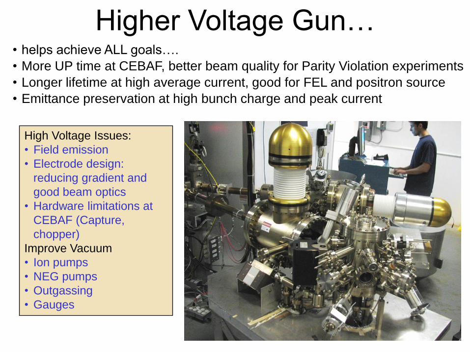
Higher Voltage Gun…• helps achieve ALL goals….
• More UP time at CEBAF, better beam quality for Parity Violation experiments
• Longer lifetime at high average current, good for FEL and positron source
• Emittance preservation at high bunch charge and peak current
High Voltage Issues:
• Field emission
• Electrode design:
reducing gradient and
good beam optics
• Hardware limitations at
CEBAF (Capture,
chopper)
Improve Vacuum
• Ion pumps
• NEG pumps
• Outgassing
• Gauges

0
0.2
0.4
0.6
0.8
1
1.2
50.00 100.00 150.00 200.00
Tran
smis
sio
n
Current (µA)
Transmission Vs Current (µA)
200KeV
115KeV
100KeV
85KeV
70KeV
Measurements at CEBAF/JLab PARMELA Simulation Results
Benchmarking PARMELA Simulation Results Against Beam-Based
Measurements at CEBAF/Jefferson Lab – work of Ashwini Jayaprakash, JLab
Message: Beam quality, including transmission, improves at higher gun voltage
0
50
100
150
200
250
300
0 50 100 150 200
Ele
ctr
on
Bu
nch
len
gth
(ps)
Ave. Gun Current (uA)
Electron Bunchlength vs Gun Voltage
115kV
100kV
85kV
70kV
0102030405060708090
100
0 50 100 150 200
Tran
smis
sio
n (%
)
Ave. Gun Current (uA)
Transmission vs Gun Voltage115kV
100kV
85kV
70kV
Reasonable agreement
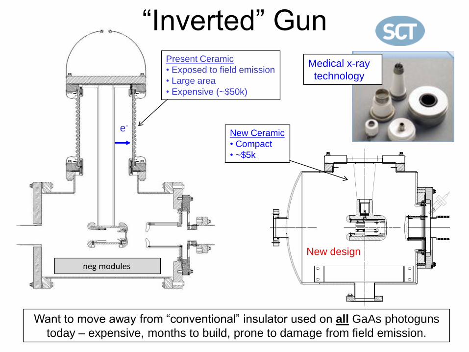
“Inverted” Gun
e-
Present Ceramic
• Exposed to field emission
• Large area
• Expensive (~$50k)
Medical x-ray
technology
New design
New Ceramic
• Compact
• ~$5k
Want to move away from “conventional” insulator used on all GaAs photoguns
today – expensive, months to build, prone to damage from field emission.
neg modules
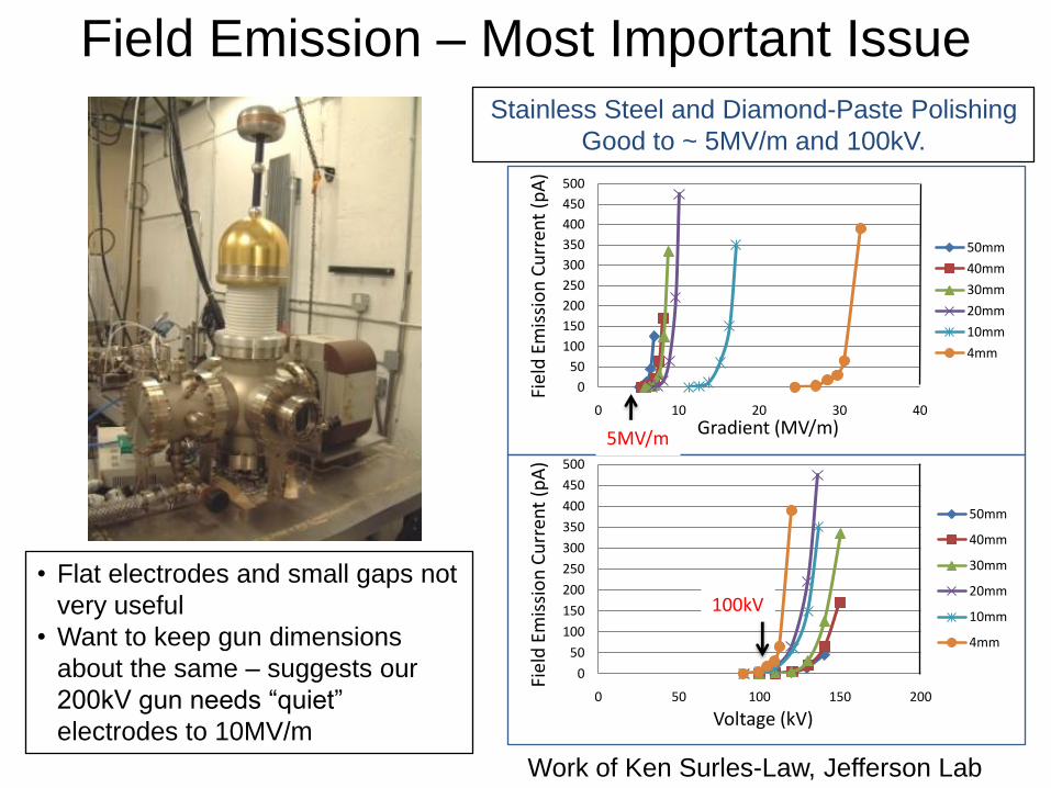
Field Emission – Most Important Issue
• Flat electrodes and small gaps not
very useful
• Want to keep gun dimensions
about the same – suggests our
200kV gun needs “quiet”
electrodes to 10MV/m
0
50
100
150
200
250
300
350
400
450
500
0 10 20 30 40
Fiel
d E
mis
sio
n C
urr
ent
(pA
)
Gradient (MV/m)
50mm
40mm
30mm
20mm
10mm
4mm
0
50
100
150
200
250
300
350
400
450
500
0 50 100 150 200
Fiel
d E
mis
sio
n C
urr
ent
(pA
)
Voltage (kV)
50mm
40mm
30mm
20mm
10mm
4mm
Stainless Steel and Diamond-Paste Polishing
Good to ~ 5MV/m and 100kV.
Work of Ken Surles-Law, Jefferson Lab
5MV/m
100kV

Replace conventional
ceramic insulator with
“Inverted” insulator: no
SF6 and no HV
breakdown outside
chamber
Conventional
geometry: cathode
electrode mounted
on metal support
structure
Single Crystal Niobium:
• Capable of operation at higher voltage
and gradient
• Buffer chemical polish (BCP) much
easier than diamond-paste-polish
Work of Ken Surles-Law, Jefferson Lab
0
20
40
60
80
100
120
140
160
180
0 50 100 150 200
Fiel
d E
mis
sio
n C
urr
ent
(pA
)
Voltage (kV)
BCP Niobium vs Stainless Steel
niobium
304 SS
304 SS #2
Thanks to P. Kneisel, L. Turlington, G. Myneni
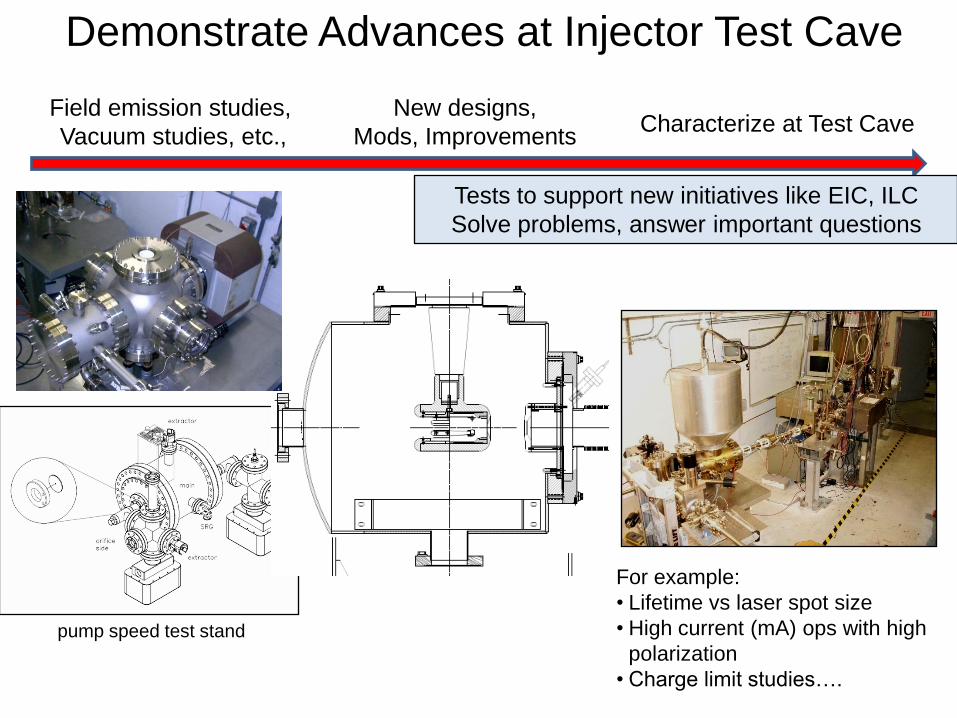
Field emission studies,
Vacuum studies, etc.,
New designs,
Mods, ImprovementsCharacterize at Test Cave
Demonstrate Advances at Injector Test Cave
Tests to support new initiatives like EIC, ILC
Solve problems, answer important questions
For example:
• Lifetime vs laser spot size
• High current (mA) ops with high
polarization
• Charge limit studies….
pump speed test stand
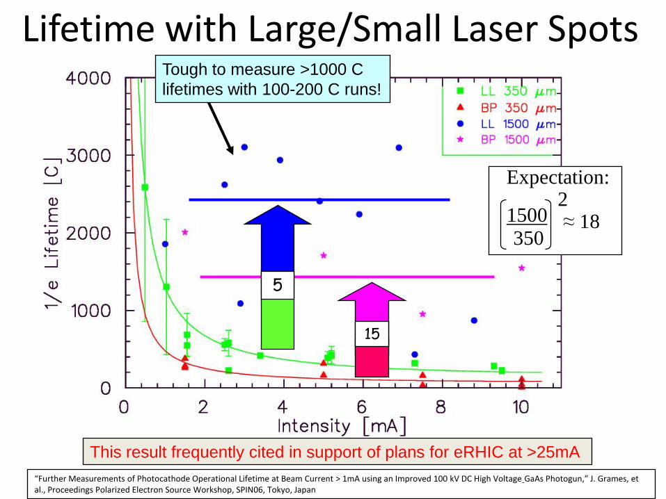
Lifetime with Large/Small Laser SpotsTough to measure >1000 C
lifetimes with 100-200 C runs!
5
15
1500350
2≈ 18
Expectation:
“Further Measurements of Photocathode Operational Lifetime at Beam Current > 1mA using an Improved 100 kV DC High Voltage GaAs Photogun,” J. Grames, et al., Proceedings Polarized Electron Source Workshop, SPIN06, Tokyo, Japan
This result frequently cited in support of plans for eRHIC at >25mA
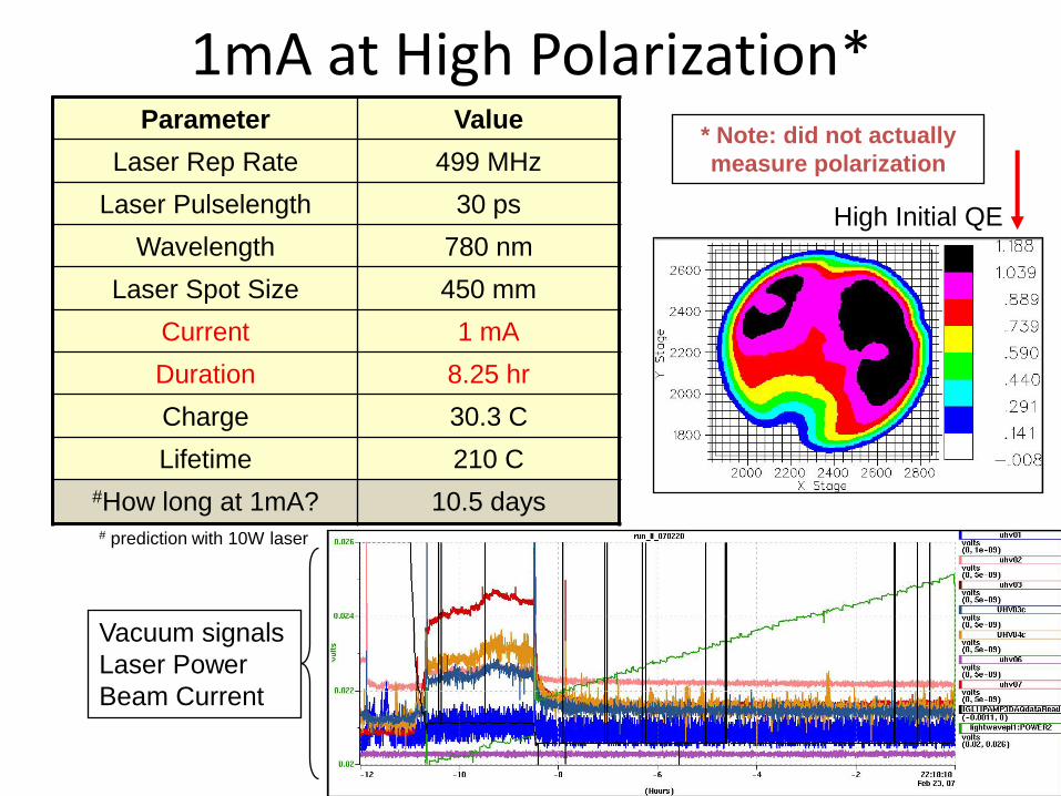
1mA at High Polarization*Parameter Value
Laser Rep Rate 499 MHz
Laser Pulselength 30 ps
Wavelength 780 nm
Laser Spot Size 450 mm
Current 1 mA
Duration 8.25 hr
Charge 30.3 C
Lifetime 210 C
#How long at 1mA? 10.5 days
High Initial QE
Vacuum signals
Laser Power
Beam Current
* Note: did not actually
measure polarization
# prediction with 10W laser
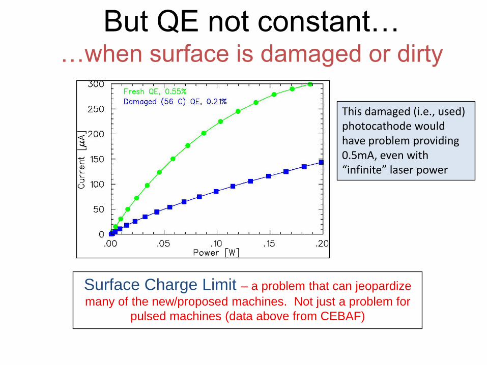
But QE not constant……when surface is damaged or dirty
Surface Charge Limit – a problem that can jeopardize
many of the new/proposed machines. Not just a problem for
pulsed machines (data above from CEBAF)
This damaged (i.e., used) photocathode would have problem providing 0.5mA, even with “infinite” laser power
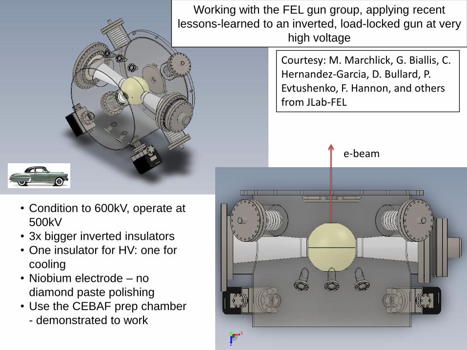
e-beam
• Condition to 600kV, operate at
500kV
• 3x bigger inverted insulators
• One insulator for HV: one for
cooling
• Niobium electrode – no
diamond paste polishing
• Use the CEBAF prep chamber
- demonstrated to work
Working with the FEL gun group, applying recent
lessons-learned to an inverted, load-locked gun at very
high voltage
Courtesy: M. Marchlick, G. Biallis, C. Hernandez-Garcia, D. Bullard, P. Evtushenko, F. Hannon, and others from JLab-FEL
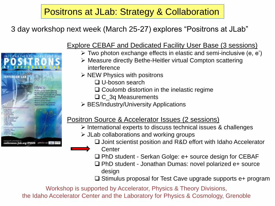
Positrons at JLab: Strategy & Collaboration
Explore CEBAF and Dedicated Facility User Base (3 sessions) Two photon exchange effects in elastic and semi-inclusive (e, e’)
Measure directly Bethe-Heitler virtual Compton scattering
interference
NEW Physics with positrons
U-boson search
Coulomb distortion in the inelastic regime
C_3q Measurements
BES/Industry/University Applications
Positron Source & Accelerator Issues (2 sessions) International experts to discuss technical issues & challenges
JLab collaborations and working groups
Joint scientist position and R&D effort with Idaho Accelerator
Center
PhD student - Serkan Golge: e+ source design for CEBAF
PhD student - Jonathan Dumas: novel polarized e+ source
design
Stimulus proposal for Test Cave upgrade supports e+ program
3 day workshop next week (March 25-27) explores “Positrons at JLab”
Workshop is supported by Accelerator, Physics & Theory Divisions,
the Idaho Accelerator Center and the Laboratory for Physics & Cosmology, Grenoble
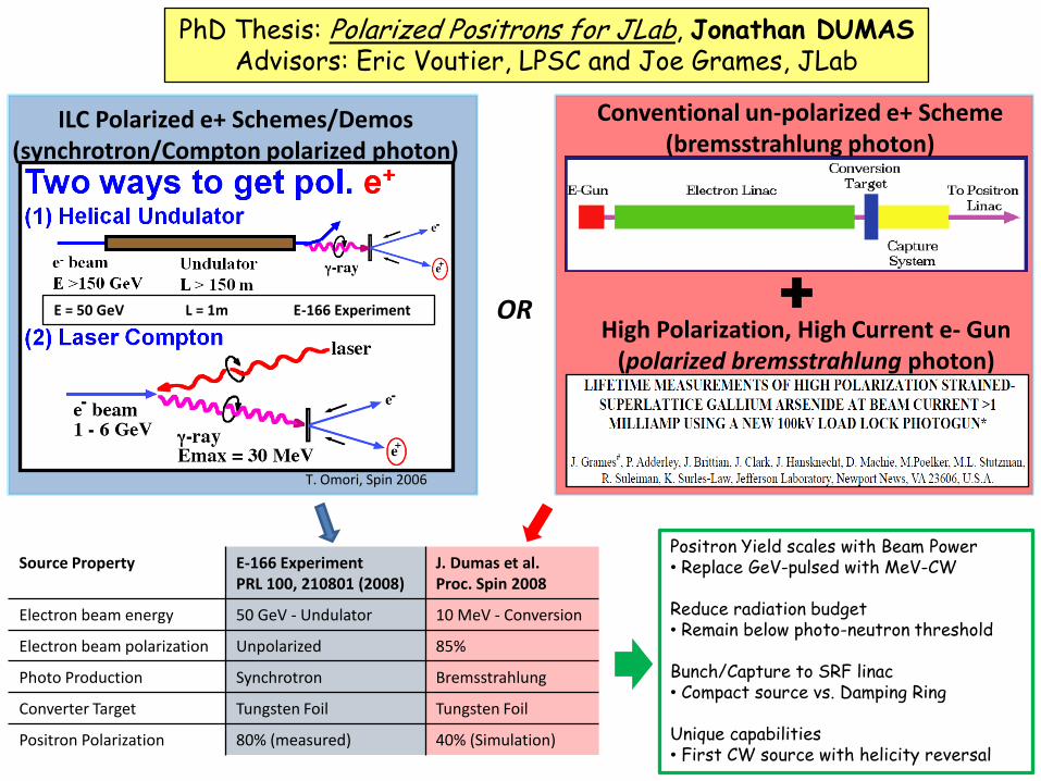
Source Property E-166 ExperimentPRL 100, 210801 (2008)
J. Dumas et al.Proc. Spin 2008
Electron beam energy 50 GeV - Undulator 10 MeV - Conversion
Electron beam polarization Unpolarized 85%
Photo Production Synchrotron Bremsstrahlung
Converter Target Tungsten Foil Tungsten Foil
Positron Polarization 80% (measured) 40% (Simulation)
PhD Thesis: Polarized Positrons for JLab, Jonathan DUMASAdvisors: Eric Voutier, LPSC and Joe Grames, JLab
ILC Polarized e+ Schemes/Demos(synchrotron/Compton polarized photon)
Conventional un-polarized e+ Scheme(bremsstrahlung photon)
High Polarization, High Current e- Gun(polarized bremsstrahlung photon)
OR
Positron Yield scales with Beam Power• Replace GeV-pulsed with MeV-CW
Reduce radiation budget• Remain below photo-neutron threshold
Bunch/Capture to SRF linac• Compact source vs. Damping Ring
Unique capabilities• First CW source with helicity reversal
T. Omori, Spin 2006
E = 50 GeV L = 1m E-166 Experiment
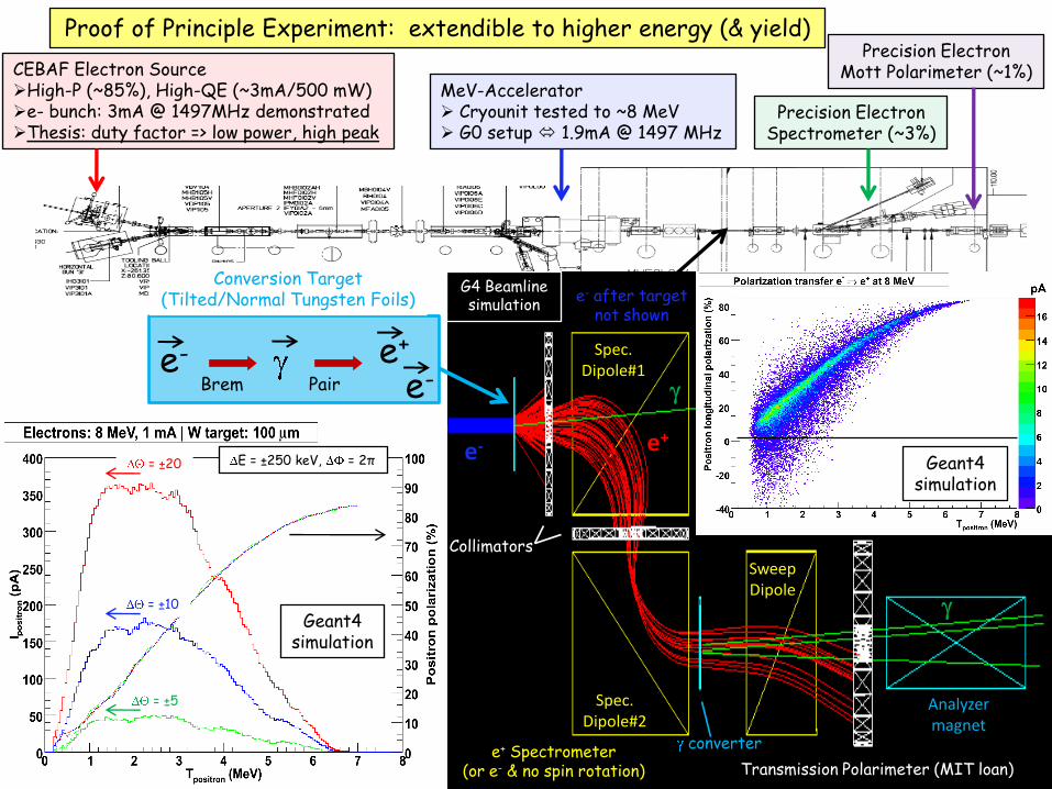
Proof of Principle Experiment: extendible to higher energy (& yield)
Precision ElectronSpectrometer (~3%)
Precision ElectronMott Polarimeter (~1%)
e- e+
e-PairBrem
CEBAF Electron SourceHigh-P (~85%), High-QE (~3mA/500 mW)e- bunch: 3mA @ 1497MHz demonstratedThesis: duty factor => low power, high peak
MeV-Accelerator Cryounit tested to ~8 MeV G0 setup 1.9mA @ 1497 MHz
e+ Spectrometer(or e- & no spin rotation) Transmission Polarimeter (MIT loan)
Conversion Target(Tilted/Normal Tungsten Foils)
= ±20
= ±10
= ±5
Collimators
Analyzer magnet
Spec.Dipole#2
Spec.Dipole#1
SweepDipole
e+
e- after targetnot shown
e-
converter
E = ±250 keV, = 2π
Geant4simulation
Geant4simulation
G4 Beamlinesimulation
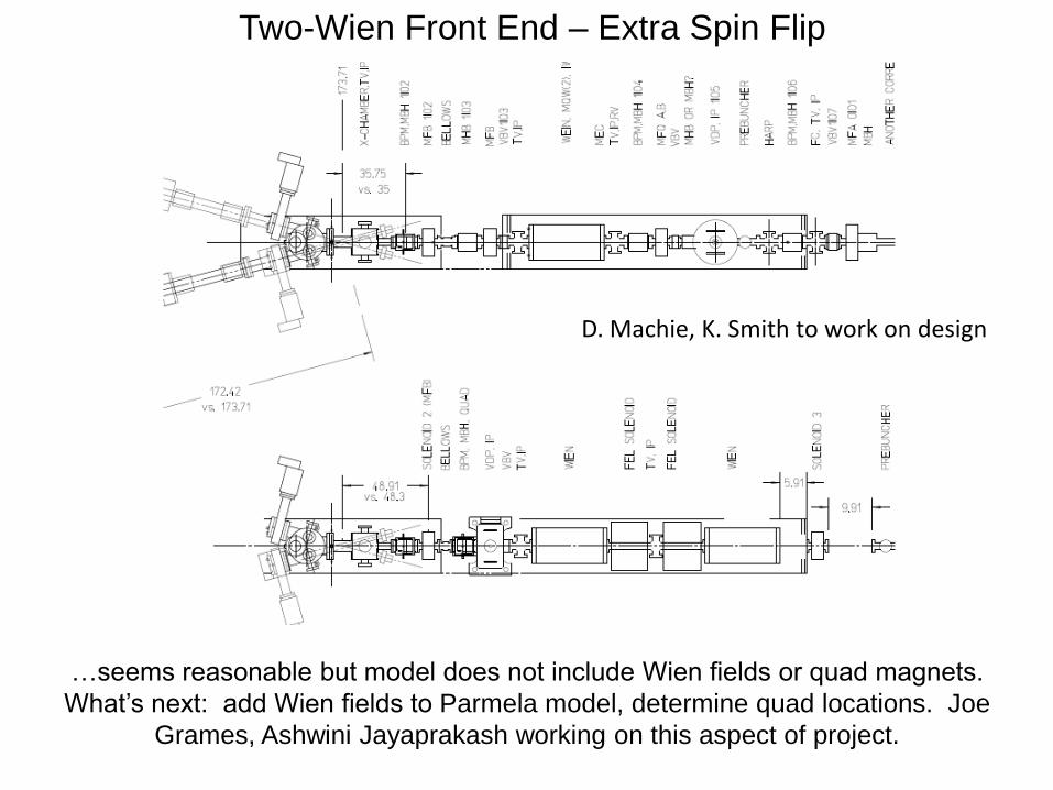
…seems reasonable but model does not include Wien fields or quad magnets.
What’s next: add Wien fields to Parmela model, determine quad locations. Joe
Grames, Ashwini Jayaprakash working on this aspect of project.
D. Machie, K. Smith to work on design
Two-Wien Front End – Extra Spin Flip
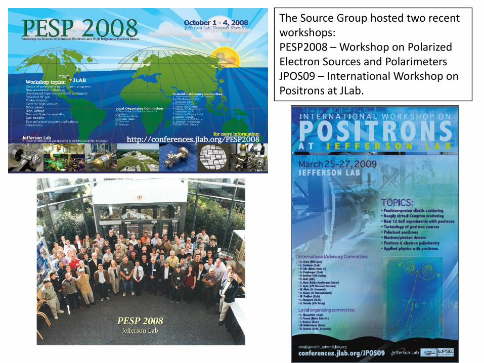
The Source Group hosted two recent workshops: PESP2008 – Workshop on Polarized Electron Sources and PolarimetersJPOS09 – International Workshop on Positrons at JLab.