injection molding of xiameter™ liquid silicone rubber
TRANSCRIPT

Injection Molding of XIAMETER™ Liquid Silicone Rubber
Consumer Solutions
PrefaceNowadays injection molding of liquid silicone rubbers is becoming increasingly important. One reason for this is the increased performance requirements of the finished articles. In addition, more and more producers of rubber parts are seeing benefits in the high level of automation and productivity.
The aim of this brochure is to illustrate to you the basics of XIAMETER™ Liquid Silicone Rubber injection molding. The content includes chapters like: material properties, mold design, and production. The chapter Trouble Shooting should help you to solve problems during the production as well as finding solutions for problems when they appear and prevent them in the future.
Plastics and Rubber
pg 2
Contents Page
Preface . . . . . . . . . . . . . . . . . . . . . . . . . . . . . . . . . . . . . . . . . . . . . . . . . . . . . . . . . . . . . . . . . . . . . . . . . . . . . . . . . . . . . . . . . . . . . . . . . . . . . . . . . . . . 1 XIAMETER™ LSR LIQUID SILICONE RUBBER . . . . . . . . . . . . . . . . . . . . . . . . . . . . . . . . . . . . . . . . . . . . . . . . . . . . . . . . . . . . . . . . . 3 General . . . . . . . . . . . . . . . . . . . . . . . . . . . . . . . . . . . . . . . . . . . . . . . . . . . . . . . . . . . . . . . . . . . . . . . . . . . . . . . . . . . . 3 Handling Precautions. . . . . . . . . . . . . . . . . . . . . . . . . . . . . . . . . . . . . . . . . . . . . . . . . . . . . . . . . . . . . . . . . . . . . . . 3 TECHNOLOGICAL ADVANTAGES OF XIAMETER LSR . . . . . . . . . . . . . . . . . . . . . . . . . . . . . . . . . . . . . . . . . . . . . . . . . . . . . . . . . . 3 APPLICATIONS . . . . . . . . . . . . . . . . . . . . . . . . . . . . . . . . . . . . . . . . . . . . . . . . . . . . . . . . . . . . . . . . . . . . . . . . . . . . . . . . . . . . . . . . . . . . . . . . 4 CHARACTERISTICS AND INJECTION MOLDING OF XIAMETER LSR . . . . . . . . . . . . . . . . . . . . . . . . . . . . . . . . . . . . . . . . . . . 4 Viscosity of XIAMETER LSR. . . . . . . . . . . . . . . . . . . . . . . . . . . . . . . . . . . . . . . . . . . . . . . . . . . . . . . . . . . . . . . . . 4 Injection. . . . . . . . . . . . . . . . . . . . . . . . . . . . . . . . . . . . . . . . . . . . . . . . . . . . . . . . . . . . . . . . . . . . . . . . . . . . . . . . . . . . 4 Holding Pressure . . . . . . . . . . . . . . . . . . . . . . . . . . . . . . . . . . . . . . . . . . . . . . . . . . . . . . . . . . . . . . . . . . . . . . . . . . . 4 Material Cushion . . . . . . . . . . . . . . . . . . . . . . . . . . . . . . . . . . . . . . . . . . . . . . . . . . . . . . . . . . . . . . . . . . . . . . . . . . . 5 Pressure in the Cavity. . . . . . . . . . . . . . . . . . . . . . . . . . . . . . . . . . . . . . . . . . . . . . . . . . . . . . . . . . . . . . . . . . . . . . . 5 Material Supply. . . . . . . . . . . . . . . . . . . . . . . . . . . . . . . . . . . . . . . . . . . . . . . . . . . . . . . . . . . . . . . . . . . . . . . . . . . . . 5 Mixing . . . . . . . . . . . . . . . . . . . . . . . . . . . . . . . . . . . . . . . . . . . . . . . . . . . . . . . . . . . . . . . . . . . . . . . . . . . . . . . . . . . . . . 5 Dosing . . . . . . . . . . . . . . . . . . . . . . . . . . . . . . . . . . . . . . . . . . . . . . . . . . . . . . . . . . . . . . . . . . . . . . . . . . . . . . . . . . . . . 5 Back Pressure. . . . . . . . . . . . . . . . . . . . . . . . . . . . . . . . . . . . . . . . . . . . . . . . . . . . . . . . . . . . . . . . . . . . . . . . . . . . . . 5 Curing Behavior of XIAMETER LSR . . . . . . . . . . . . . . . . . . . . . . . . . . . . . . . . . . . . . . . . . . . . . . . . . . . . . . . . . 6 Post Curing . . . . . . . . . . . . . . . . . . . . . . . . . . . . . . . . . . . . . . . . . . . . . . . . . . . . . . . . . . . . . . . . . . . . . . . . . . . . . . . . 7 PRINCIPLES OF MOLD DESIGN FOR XIAMETER LSR . . . . . . . . . . . . . . . . . . . . . . . . . . . . . . . . . . . . . . . . . . . . . . . . . . . . . . . . . . 8 Shrinkage . . . . . . . . . . . . . . . . . . . . . . . . . . . . . . . . . . . . . . . . . . . . . . . . . . . . . . . . . . . . . . . . . . . . . . . . . . . . . . . . . . 8 Parting Line . . . . . . . . . . . . . . . . . . . . . . . . . . . . . . . . . . . . . . . . . . . . . . . . . . . . . . . . . . . . . . . . . . . . . . . . . . . . . . . . 9 Venting. . . . . . . . . . . . . . . . . . . . . . . . . . . . . . . . . . . . . . . . . . . . . . . . . . . . . . . . . . . . . . . . . . . . . . . . . . . . . . . . . . . . . 9 Injection Point . . . . . . . . . . . . . . . . . . . . . . . . . . . . . . . . . . . . . . . . . . . . . . . . . . . . . . . . . . . . . . . . . . . . . . . . . . . . . . 9 Demolding and Ejector Systems . . . . . . . . . . . . . . . . . . . . . . . . . . . . . . . . . . . . . . . . . . . . . . . . . . . . . . . . . . 10 Mold Materials. . . . . . . . . . . . . . . . . . . . . . . . . . . . . . . . . . . . . . . . . . . . . . . . . . . . . . . . . . . . . . . . . . . . . . . . . . . . 10 Cavity Surface Finish . . . . . . . . . . . . . . . . . . . . . . . . . . . . . . . . . . . . . . . . . . . . . . . . . . . . . . . . . . . . . . . . . . . . . 10 Temperature Control . . . . . . . . . . . . . . . . . . . . . . . . . . . . . . . . . . . . . . . . . . . . . . . . . . . . . . . . . . . . . . . . . . . . . 10 SELECTION OF MACHINE . . . . . . . . . . . . . . . . . . . . . . . . . . . . . . . . . . . . . . . . . . . . . . . . . . . . . . . . . . . . . . . . . . . . . . . . . . . . . . . . . . . . 11 Clamping Force . . . . . . . . . . . . . . . . . . . . . . . . . . . . . . . . . . . . . . . . . . . . . . . . . . . . . . . . . . . . . . . . . . . . . . . . . . . 11 Injection Unit . . . . . . . . . . . . . . . . . . . . . . . . . . . . . . . . . . . . . . . . . . . . . . . . . . . . . . . . . . . . . . . . . . . . . . . . . . . . . . 11 Meter Mixer. . . . . . . . . . . . . . . . . . . . . . . . . . . . . . . . . . . . . . . . . . . . . . . . . . . . . . . . . . . . . . . . . . . . . . . . . . . . . . . . 11 OTHER INJECTION MOLDING TECHNOLOGIES . . . . . . . . . . . . . . . . . . . . . . . . . . . . . . . . . . . . . . . . . . . . . . . . . . . . . . . . . . . . . . 11 Two-Component Injection Molding . . . . . . . . . . . . . . . . . . . . . . . . . . . . . . . . . . . . . . . . . . . . . . . . . . . . . . . . 11 STARTING THE PRODUCTION. . . . . . . . . . . . . . . . . . . . . . . . . . . . . . . . . . . . . . . . . . . . . . . . . . . . . . . . . . . . . . . . . . . . . . . . . . . . . . . 12 Temperature Preset . . . . . . . . . . . . . . . . . . . . . . . . . . . . . . . . . . . . . . . . . . . . . . . . . . . . . . . . . . . . . . . . . . . . . . 12 Injection Stroke and Flow . . . . . . . . . . . . . . . . . . . . . . . . . . . . . . . . . . . . . . . . . . . . . . . . . . . . . . . . . . . . . . . . . 12 Switch Over and Holding Pressure . . . . . . . . . . . . . . . . . . . . . . . . . . . . . . . . . . . . . . . . . . . . . . . . . . . . . . . . 13 Curing Time . . . . . . . . . . . . . . . . . . . . . . . . . . . . . . . . . . . . . . . . . . . . . . . . . . . . . . . . . . . . . . . . . . . . . . . . . . . . . . 13 Demolding . . . . . . . . . . . . . . . . . . . . . . . . . . . . . . . . . . . . . . . . . . . . . . . . . . . . . . . . . . . . . . . . . . . . . . . . . . . . . . . 13 Production End and Clean-Up . . . . . . . . . . . . . . . . . . . . . . . . . . . . . . . . . . . . . . . . . . . . . . . . . . . . . . . . . . . . 13 TROUBLE SHOOTING FOR INJECTION MOLDING OF XIAMETER LSR . . . . . . . . . . . . . . . . . . . . . . . . . . . . . . . . . . . . . . . 14
Injection Molding of XIAMETER™ Liquid Silicone Rubber | 2009

pg 3
General
Description Liquid silicone rubber was pioneered by Dow and introduced to the rubber fabrication marketplace in the late seventies. Today the processing and product advantages of XIAMETER LSR are exploited in many existing and new applications. A broad product line is available.
Key Elements of XIAMETER LSR XIAMETER LSRs are liquids with viscosities that vary from easily pourable to pastes. These two-component materials are mostly
XIAMETER™ LSR Liquid Silicone Rubber
used in a 1-to-1 ratio and consist of poysiloxane polymers or copolymers that are vulcanized by polyaddition.
Packaging XIAMETER liquid silicone rubbers are supplied as lot matched kits in drums or pails. The exact packaging weight does vary, depending on the density of the product.
Usable Life and Storage When stored at or below 32°C in the original unopened containers, Dow will guarantee the usable life of these products until the date indicated on the packaging and they will have a usable life of at
least 6 months when shipped. This date is shown by the letters “EXP” (meaning expire) followed by four digits, which stand for the month (last day) and year).
Example “EXP” 03/10 means use by March 31, 2010.
Handling Precautions A product safety data sheet should be obtained prior to use. Attention: Before handling read product information, product safety data sheet, and container labels for safe end use and physical and/or health hazard information.
Principal Advantages of Addition Cure
• no cure decomposition products (unlike peroxides)
• long pot life at room temperature yet very fast vulcanization above 150°C
Technological Advantages of XIAMETER LSR
• fully compounded, ready to process
• easily pigmented, providing end product flexibility
• automated injection molding process similar to thermoplastic injection molding
• easy demolding with good hot tear
• very short and highly productive cycle times
Technological Advantages of XIAMETER LSR
• flashless molding with tight part size tolerance control
• post curing frequently not needed
• good direct bonding to specific insert components
• superior clarity as well as low odor and neutral taste
• usable over a wide temperature range from -60°C to +180°C
• good elastic properties
• very good UV and ozone resistance as well as atmospheric aging stability
• low moisture pick-up and resistant to many solvents
• good dielectric properties over a wide temperature range
Injection Molding of XIAMETER™ Liquid Silicone Rubber | 2009
pg 4
Applications
Applications for XIAMETER™ LSR
XIAMETER LSRs are widely used in injection molding, fabric coating, dipping, and extrusion coating processes. Applications are very numerous including the automotive, aerospace, appliance, business machine, electrical, and consumers industries.
Food Contact with XIAMETER LSR
Certain XIAMETER LSR grades comply with FDA food regulation 21 CFR 177.2600 and BgVV (formerly BGA) XV when correctly processed.
Extrusion and Flat Textile Coating
Liquid silicone rubbers are very suited to these processes for reasons of:
• solventless with low and versatile viscosity
• easy mixing and pigmentation
• rapid processing compared to solvent dispersions and usually allow a complete coating to be applied in a single pass
• primerless adhesion to glass and certain other substrates
Meter mixed XIAMETER LSR can be dip coated or fed to a crosshead for supported extrusion coating. Standard techniques are used for flat textile coating.
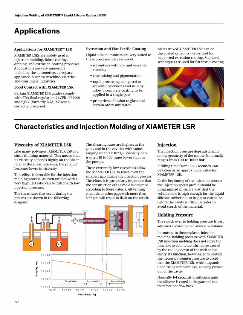
Viscosity of XIAMETER LSRLike many polymers, XIAMETER LSR is a shear thinning material. This means that its viscosity depends highly on the shear rate; as the shear rate rises, the product becomes lower in viscosity.
This effect is favorable for the injection molding process, as even articles with a very high LID ratio can be filled with low injection pressure.
The shear rates that occur during the process are shown in the following diagram:
Characteristics and Injection Molding of XIAMETER LSR
Injection The injection pressure depends mainly on the geometry of the runner. It normally ranges from 100 to 1000 bar.
A filling time from 0.5-3 seconds can be taken as an approximate value for XIAMETER LSR.
At the beginning of the injection process the injection speed profile should be programmed in such a way that the volume flow is high enough for the liquid silicone rubber not to begin to vulcanize before the cavity is filled, in order to avoid scorch of the material.
Holding PressureThe switch over to holding pressure 1s best adjusted according to distance or volume.
In contrast to thermoplastic injection molding, holding pressure with XIAMETER LSR injection molding does not serve the function to counteract shrinkage caused by the cooling down of the melt in the cavity. Its function, however, is to provide the necessary counterpressure to avoid that the XIAMETER LSR, which expands upon rising temperatures, is being pushed out of the cavity.
Normally 1-4 seconds is sufficient until the silicone is cured at the gate and can therefore not flow back.
Injection Molding of XIAMETER™ Liquid Silicone Rubber | 2009
The shearing rates are highest at the gates and in the cavities with values ranging up to 1 x 10⁻⁴ 1/s. Viscosity here is often 10 to 100 times lower than in the pumps.
These extremely low viscosities allow the XIAMETER LSR to reach even the smallest gap during the injection process. Therefore, it is particularly important that the construction of the mold is designed according to these criteria. All venting channels or other gaps with more then 5-7.5 μm will result in flash on the article.
Shear Rate [1/s]
A B
Pump/Mixer Injection Unit Runner/Cavity
Visc
osit
y [P
as]

pg 5
Material CushionTo avoid over loading, it is advisable to drive the material cushion towards zero.
Pressure in the CavityCavity pressure increases gradually as the injected silicone expands upon rising temperature.
This rising pressure caused by the heat expansion occurs earlier than the vulcanization. Due to this effect, even shortly after the filling process, the material can be pressed into small gaps as it is not sufficiently vulcanized in the outer layer. If the cavity is filled precisely with a volume of 98-99%, the remaining filling of the cavity is brought about by the expansion of the material in the hot mold. Since the cavity pressure does not rise so high compared to when a cavity is filled 100% before thermal expansion, flash can thereby be prevented.
This precise filling requires a perfect handling of the injection molding machine. The complete machine movements must be identically repeated again and again with a high precision. Cavity pressure commonly measures up to 300 bar.
Material SupplyThe two XIAMETER LSR components are delivered at a rate of one to one from drums or pails by hydraulically or pneumatically driven reciprocating pumps through flexible pipes to a static mixer. Here the pressure in the XIAMETER LSR measures 150-220 bar. Also, 0.5-6% color additive can be added at this point.
If more than one color is frequently used on the same machine or if more than one injection unit is being supplied from the same pump, further additive pumps can be linked up.
MixingThe two main components and possibly an additive are delivered through a static mixer, which is a pipe with staggered mixing vanes inside and hence almost homogeneously mixed.
DosingThe injection unit often has just one feeding screw for processing XIAMETER LSR. This means, the proportion of compression is 1:1. To guarantee an optimal mixing of the material, sometimes feeding screws with an additional mixing unit in the metering
Injection Speed Profile
zone are employed. Some special machines use a dynamic mixer combined with an injection piston to dose the material.
Special attention should be given to the non-return valve. It must be equipped with an exact and reproducible closing mechanism to avoid variations in the final volume caused by leakage flow.
Due to the very low viscosity as compared with thermoplastic melts, standard non-return valves are often too inert and do not always close immediately when the screw begins the injection process. Good results can be achieved with spring-loaded rings or with such non-return valves, which
have very small closing distances for the particular application.
The dosing speed should be chosen in such a manner that it:
• does not prolong the cycle time,
• does not increase the temperature of the XIAMETER LSR and thereby cause partial curing.
Back PressureThe specific back pressure should be adjusted to 5-30 bar.
Pressure in the Mold
Time [s]
Pres
sure
[bar
]
200
150
100
50
00 2 4 6 8 10
Injection Curing
Runner
Cavity
Injection Molding of XIAMETER™ Liquid Silicone Rubber | 2009
Inje
ctio
n Ve
loci
ty [c
m3 s]
Injection Time [s]
60
50
40
30
20
10
0
0 0.5 1 1.5

pg 6
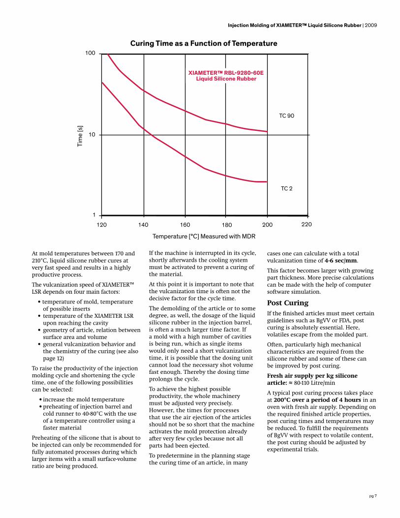
liquid silicone rubber begins to adopt the heat of the chamber, the torque begins to rise due to the beginning of the vulcanization.
The designation TC 2 shows the time at which 2% of the maximum torque is reached during the test. This TC 2 value gives an indication of when the curing starts.
The TC 90 value is important. Here, 90% of the maximum torque is reached and as the curing is so far advanced that during the course of an injection molding process, demolding is possible.
At 25°C it takes several weeks until the material is completely vulcanized. At temperatures above 120°C, however, this reaction takes only a few seconds.
H
C
Si O
H H
CH HH
R Si
H
CH H
CH HH
n
CC
H
H
H
H Si C H
H
HO
O
C H
H
H
Si C H
H
H
CH
H
H
R
Si C H
H
H
CH
H
H
+Pt
Poly-DiMethyl-Siloxane
Catalyst
H
C
Si O
H H
CH HH
R Si
H
CH H
CH HH
n
H
CH
C
H H
Si C H
H
HO
O
C H
H
H
Si C H
H
H
CH
H
H
R
Si C H
H
H
CH
H
H
Injection Molding of XIAMETER™ Liquid Silicone Rubber | 2009
Curing Behavior of XIAMETER™ LSRVinyl and hydrogen functional polysiloxanes are cured using a platinum catalyst. This reaction proceeds at room temperature but is accelerated rapidly by increasing the temperature. A mixed XIAMETER LSR, when stored at room temperature, has a minimum usage time (pot life) of 3 days.
When the curing of a liquid silicone rubber is measured on a rheometer, one obtains the torque as a function of the test time.
The diagram shows the various stages of cure. In the beginning, the sample is mainly plastic and shows very little resistance to the deformation caused by the testing equipment. When the
Curing of XIAMETER LSR
Torq
ue [d
Nm
]
18
16
14
12
10
8
6
4
2
00 2 4 6 8
Time [min]Measured with MOR at 120°C
XIAMETER™ RBL-9280-50E Liquid Silicone Rubber
90 % Cured
XIAMETER™ RBL-9780-50E Liquid Silicone Rubber
pg 7
At mold temperatures between 170 and 210°C, liquid silicone rubber cures at very fast speed and results in a highly productive process.
The vulcanization speed of XIAMETER™ LSR depends on four main factors:
• temperature of mold, temperature of possible inserts
• temperature of the XIAMETER LSR upon reaching the cavity
• geometry of article, relation between surface area and volume
• general vulcanization behavior and the chemistry of the curing (see also page 12)
To raise the productivity of the injection molding cycle and shortening the cycle time, one of the following possibilities can be selected:
• increase the mold temperature• preheating of injection barrel and
cold runner to 40-80°C with the use of a temperature controller using a faster material
Preheating of the silicone that is about to be injected can only be recommended for fully automated processes during which larger items with a small surface-volume ratio are being produced.
If the machine is interrupted in its cycle, shortly afterwards the cooling system must be activated to prevent a curing of the material.
At this point it is important to note that the vulcanization time is often not the decisive factor for the cycle time.
The demolding of the article or to some degree, as well, the dosage of the liquid silicone rubber in the injection barrel, is often a much larger time factor. If a mold with a high number of cavities is being run, which as single items would only need a short vulcanization time, it is possible that the dosing unit cannot load the necessary shot volume fast enough. Thereby the dosing time prolongs the cycle.
To achieve the highest possible productivity, the whole machinery must be adjusted very precisely. However, the times for processes that use the air ejection of the articles should not be so short that the machine activates the mold protection already after very few cycles because not all parts had been ejected.
To predetermine in the planning stage the curing time of an article, in many
cases one can calculate with a total vulcanization time of 4-6 sec/mm.
This factor becomes larger with growing part thickness. More precise calculations can be made with the help of computer software simulation.
Post CuringIf the finished articles must meet certain guidelines such as BgVV or FDA, post curing is absolutely essential. Here, volatiles escape from the molded part.
Often, particularly high mechanical characteristics are required from the silicone rubber and some of these can be improved by post curing.
Fresh air supply per kg silicone article: ≈ 80-110 Litre/min
A typical post curing process takes place at 200°C over a period of 4 hours in an oven with fresh air supply. Depending on the required finished article properties, post curing times and temperatures may be reduced. To fulfill the requirements of BgVV with respect to volatile content, the post curing should be adjusted by experimental trials.
Injection Molding of XIAMETER™ Liquid Silicone Rubber | 2009
Curing Time as a Function of Temperature
Tim
e [s
]
100
10
1
120
Temperature [°C] Measured with MDR
140 160 180 200 220
XIAMETER™ RBL-9280-60E Liquid Silicone Rubber
TC 90
TC 2

pg 8
The design of injection molds for Liquid Silicone Rubber is generally speaking similar to the design of molds for thermoplastic. Nevertheless, a few important differences of the behaviour of XIAMETER™ LSR should be noted.
Due to the relatively low viscosity of the XIAMETER LSR, the filling times of the cavity are very short even at low injection pressures. In order to avoid air entrapments, a good venting of the mold is necessary.
XIAMETER LSR does not shrink in the mold like a thermoplastic material. The liquid silicone rubber expands in the hot mold. Therefore, the articles do not necessarily remain on a core or more generally on the positive side of the mold as desired. Usually, the articles remain in the cavity half with the larger surface area.
ShrinkageEven if the articles do not shrink in the mold, they will shrink about 2.5-3% after the demolding and the following cooling process.
This shrinkage depends on several factors:• tool temperature and demolding temperature• pressure in the cavity and consequently the compression of the materials• location of injection point (shrinkage in the direction of the material flow is usually somewhat higher than perpendicular to the direction of flow)• the dimension of the part (the shrinkage of thicker articles is lower than of thinner articles)• post curing the article causes additional shrinkage of about 0.5-0.7%
Principles of Mold Design for XIAMETER™ LSR
pvt - Diagram XIAMETER™ RBL-9280-50E Liquid Silicone Rubber
Spec
. Vol
ume
[cm
3 /g]
1,025
Temperature [°C ]
0,975
0,925
0,875
0,825
50 100 150 200 250
1 bar
Shrinkage XIAMETER™ RBL-9280-50E Liquid Silicone Rubber
Shrin
kage
[%]
5
Temperature [°C ]
4
3
2
1
140 160 180 200 220
200 bar
Injection Molding of XIAMETER™ Liquid Silicone Rubber | 2009
200 bar
400 bar
600 bar
800 bar
pg 9
20-30˚
45˚
0,2-0,5
Parting LineThe decision about the location of the parting line is one of the first steps during the development of the injection mold.
The venting, which is necessary for the material flow, functions through venting channels that are inserted into the parting line. It should therefore be located in the area the material reaches last. In this manner air entrapments are avoided and the mechanical strength of the articles is not reduced along the weld line.
On the molded article the separation from the mold is always recognizable later on. This area is very sensitive due to the low viscosity of the XIAMETER™ LSR and can easily bring about flash.
Demolding of the articles at a later point in time is influenced by the geometry of the part and location of the parting line. Under cuts here can result in a consistent affinity of the part to the desired cavity half.
VentingThe air that is enclosed in the cavity is first compressed by the injected XIAMETER LSR and than expelled through the venting channels. If the air can not escape entirely, air entrapments in the article occur, which can often be recognized by a white edge along the article.
Special venting channels with 1-3 mm width and 0.004-0.005 mm depth are inserted into the parting line so the air can escape.
Optimum venting is created by a vacuum. To produce such a vacuum, the mold stops during the closing movement at 0.5-2 mm before it is completely closed. A gasket is built into the parting line, so a vacuum pump can draw the air from the cavities. Only when the vacuum has reached a certain reduced pressure or a time cycle has come to its finish, the machine closes the mold completely and the injection process is started.
Some modern injection molding machines allow operating with different clamping forces. Here the mold is held together with low force until the cavities are 90-95% filled. The air can thereby better escape through the parting line.
Then switching to the higher necessary clamping force avoids flash caused by the expanding silicone.
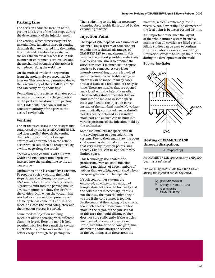
Injection PointThe type of gate depends on a number of factors. Using a system of cold runners exploits the technical advantages of XIAMETER LSR to a maximum. In this manner the highest possible productivity is achieved. The aim is to produce the articles in such a manner that no sprue needs to be removed. A very labor-intensive reworking process is avoided and sometimes considerable savings in material can be made. In many cases this also leads to a reduction of the cycle time. There are nozzles that are opened and closed with the help of a needle. These needles shut off nozzles that are built into the mold or in some special cases are fixed to the injection barrel instead of the standard nozzle. Nowadays pneumatically controlled needle shutoff nozzles can be obtained as a standard mold part and as such can be built into various positions of the injection mold by the toolmaker.
Some moldmakers are specialized in the development of open cold runner systems. Due to their small size, the open cold runner systems makes it possible that very many injection points, and thereby cavities, can be applied in very limited space.
This technology also enables the production, even on small injection molding machines, of large numbers of articles that are of high quality and where no sprue gate needs to be separated.
If such cold runner systems are employed, an efficient separation of temperature between the hot cavity and the cold runner is necessary. If this is not the case, the material might begin to cure if the cold runner is too hot. Furthermore, if the cooling is too strong, too much heat is drawn from the hot mold in the region of the gate so that in this area the liquid silicone rubber does not cure sufficiently. If the articles are injected in a more conventional sprue, like submarine or cone gate, small diameters should always be selected in the beginning as in these areas the
material, which is extremely low in viscosity, can flow easily. The diameter of the feed point is between 0.2 and 0.5 mm.
It is important to balance the layout of the whole runner system in such a manner that all cavities are filled evenly. Filling studies can be used to confirm this information or one can use filling simulation software to design the runner during the development of the mold
Submarine Gate:
Heating of XIAMETER LSR through dissipation:
ΔT Δp/( x cp)
For XIAMETER LSR approximately 4-6K/100 bar can be calculated.
The warming that results from the friction during the injection can be neglected.
Δp pressure gradient density XIAMETER LSRcp heat capacity
XIAMETER LSR
Injection Molding of XIAMETER™ Liquid Silicone Rubber | 2009
pg 10
Demolding and Ejector SystemsDue to the fact that vulcanized liquid silicone rubbers stick to metallic surfaces and that the molded part is flexible, the demolding of injection molded articles is not particularly easy.
The high hot tear resistance of XIAMETER™ liquid silicone rubber makes it possible to demold even articles with big undercuts without damage.
The demolding technologies most often employed are:
• stripper plate• ejector pin• air eject• roller sweep• draw-off plate• robotic handling
When ejector systems are used, compliance with exact tolerances must also be paid close attention. If there is too much clearance between ejector pin and bushing guide or this has been enlarged by wear over the production time, flash must be expected.
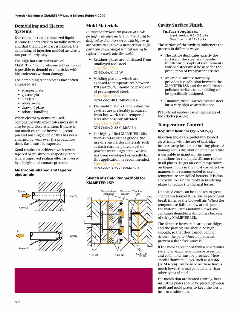
Good results are achieved with reverse tapered or mushroom shaped ejectors where improved sealing effect is favored by a heightened contact pressure.
Mushroom-shaped and tapered ejector pin:
Mold MaterialsDuring the development process of molds for highly abrasive materials, they should be designed so that those areas with high wear are constructed in such a manner that single parts can be exchanged without having to replace the whole injection mold
• Retainer plates are fabricated from unalloyed tool steel.
Steel-No.: 1.1730 DIN-Code: C 45 W
• Molding platens, which are exposed to temperatures between 170 and 210°C, should be made out of pretempered steel.
Steel-No.: 1.2312 DIN-Code: 40 CrMnMoS 8 6
• The mold platens that contain the cavities are preferably produced from hot work steel, tempered later and possibly nitrided.
Steel-No.: 1.2343 DIN-Code: X 38 CrMoV 5 1
• For highly filled XIAMETER LSRs such as oil-resistant grades, the use of even harder materials such as flash chrome-plated steel or powder metallurgy steel, which has been developed especially for this application, is recommended.Steel-No.: 1.2379
DIN-Code: X 155 CrVMo 12 1
Cavity Surface FinishSurface roughness:
Spark erosion: 0.5 - 3.5 μRa Grind, polish: 0.05 - 1 μRa
The surface of the cavities influences the process in different ways:
• The article duplicates exactly the surface of the steel and thereby fulfills various optical requirements. Polished steel must be used for the production of transparent articles.
• An eroded surface normally provides less adhesion between the XIAMETER LSR and the mold than a polished surface, so demolding can be specifically designed.
• Titanium/Nickel surface-treated steel has a very high wear resistance.
PTFE/Nickel renders easier demolding of the articles possible.
Temperature ControlRequired heat energy: ≈ 50 W/kg
Injection molds are preferably heated electrically with the use of cartridge heaters, strip heaters, or heating plates. A homogeneous distribution of temperature is desirable to maintain the same conditions for the liquid silicone rubber in all places. To get an even temperature on larger molds in the most cost-effective manner, it is recommended to use oil temperature-controlled heaters. It is also advisable to case the mold in insulating plates to reduce the thermal losses.
Unheated cores can be exposed to great changes in temperature due to prolonged break times or the blow-off air. When the temperature falls too low at this point, the material cures notably slower and can cause demolding difficulties because of sticky XIAMETER LSR.
The distance between heating cartridges and the parting line should be high enough, so that they cannot bend or deform the plate. Uneven plates can prevent a flash-free process.
If the mold is equipped with a cold runner system, an exact separation between hot and cold mold must be provided. Here special titanium alloys, such as 3.7165 (Ti Al 6 V4), can be used as these have a much lower thermal conductivity than other types of steel.
For molds that are heated entirely, heat insulating plates should be placed between mold and mold plates to keep the loss of heat to a minimum.
Injection Molding of XIAMETER™ Liquid Silicone Rubber | 2009
Sketch of a Cold Runner Mold for XIAMETER LSR
Aireject
Pin
Cavity
Cavity
Aireject
Ejector TemperatureInsulating
Vacuum- Gasket
Titanium Alloy
1.1730 1.2312 1.2343 or 1.2379
pg 11
Clamping Force
Acircle = D2π/4
Upon selection of the machine, the required clamping force must be determined. The expansion of the silicone rubber in the hot mold causes the rise of cavity pressure up to 400 bar. The force needed to clamp the mold can be calculated by multiplying the projected surface of all articles with the cavity pressure.
Due to the relatively low viscosity of the XIAMETER™ LSR, the filling times of the cavity are very short even at low injection pressures. In order to avoid air entrapments, a good venting of the mold is necessary.
Selection of Machine
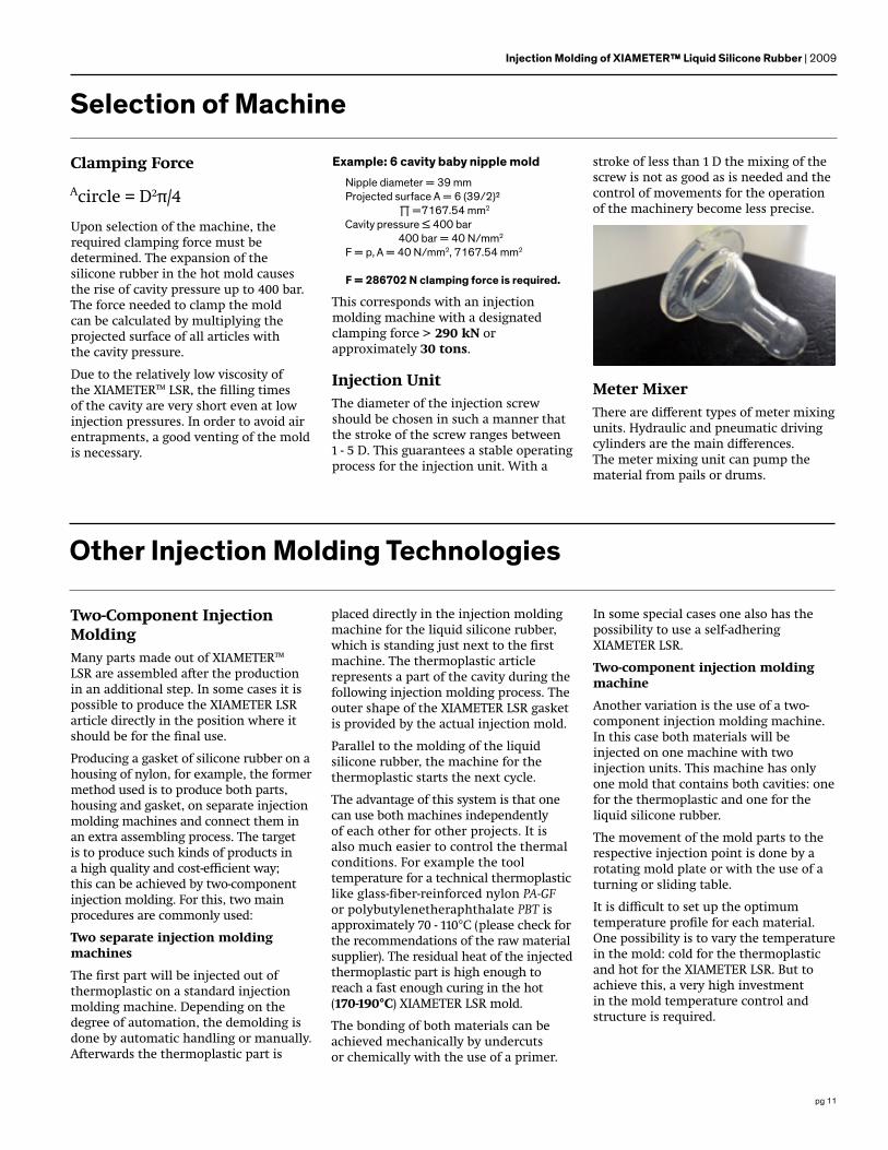
Example: 6 cavity baby nipple moldNipple diameter = 39 mmProjected surface A = 6 (39/2)² Π =7167.54 mm2
Cavity pressure ≤ 400 bar 400 bar = 40 N/mm2
F = p, A = 40 N/mm2, 7167.54 mm2
F = 286702 N clamping force is required.
This corresponds with an injection molding machine with a designated clamping force > 290 kN or approximately 30 tons.
Injection UnitThe diameter of the injection screw should be chosen in such a manner that the stroke of the screw ranges between 1 - 5 D. This guarantees a stable operating process for the injection unit. With a
stroke of less than 1 D the mixing of the screw is not as good as is needed and the control of movements for the operation of the machinery become less precise.
Two-Component Injection Molding Many parts made out of XIAMETER™ LSR are assembled after the production in an additional step. In some cases it is possible to produce the XIAMETER LSR article directly in the position where it should be for the final use.
Producing a gasket of silicone rubber on a housing of nylon, for example, the former method used is to produce both parts, housing and gasket, on separate injection molding machines and connect them in an extra assembling process. The target is to produce such kinds of products in a high quality and cost-efficient way; this can be achieved by two-component injection molding. For this, two main procedures are commonly used:
Two separate injection molding machines
The first part will be injected out of thermoplastic on a standard injection molding machine. Depending on thedegree of automation, the demolding is done by automatic handling or manually. Afterwards the thermoplastic part is
Other Injection Molding Technologies
placed directly in the injection molding machine for the liquid silicone rubber, which is standing just next to the firstmachine. The thermoplastic article represents a part of the cavity during the following injection molding process. Theouter shape of the XIAMETER LSR gasket is provided by the actual injection mold.
Parallel to the molding of the liquid silicone rubber, the machine for the thermoplastic starts the next cycle.
The advantage of this system is that one can use both machines independently of each other for other projects. It is also much easier to control the thermal conditions. For example the tool temperature for a technical thermoplastic like glass-fiber-reinforced nylon PA-GF or polybutylenetheraphthalate PBT is approximately 70 - 110°C (please check for the recommendations of the raw material supplier). The residual heat of the injected thermoplastic part is high enough to reach a fast enough curing in the hot (170-190°C) XIAMETER LSR mold.
The bonding of both materials can be achieved mechanically by undercuts or chemically with the use of a primer.
In some special cases one also has the possibility to use a self-adheringXIAMETER LSR.
Two-component injection molding machine
Another variation is the use of a two-component injection molding machine. In this case both materials will be injected on one machine with two injection units. This machine has only one mold that contains both cavities: one for the thermoplastic and one for the liquid silicone rubber.
The movement of the mold parts to the respective injection point is done by a rotating mold plate or with the use of aturning or sliding table.
It is difficult to set up the optimum temperature profile for each material. One possibility is to vary the temperature in the mold: cold for the thermoplastic and hot for the XIAMETER LSR. But to achieve this, a very high investment in the mold temperature control and structure is required.
Injection Molding of XIAMETER™ Liquid Silicone Rubber | 2009
Meter MixerThere are different types of meter mixing units. Hydraulic and pneumatic driving cylinders are the main differences. The meter mixing unit can pump the material from pails or drums.
pg 12
This type of XIAMETER LSR vulcanizes at lower tool temperatures fast enough to achieve an efficient process.
It is certainly possible to produce other two-component articles in this way or with similar procedures:
• silicone with silicone for multi-color articles
• electrically conductive silicone in combination with insulating ones for high-voltage applications
• injection of silicone gaskets on aluminium housings -MIPG (Mold In Place Gasket)
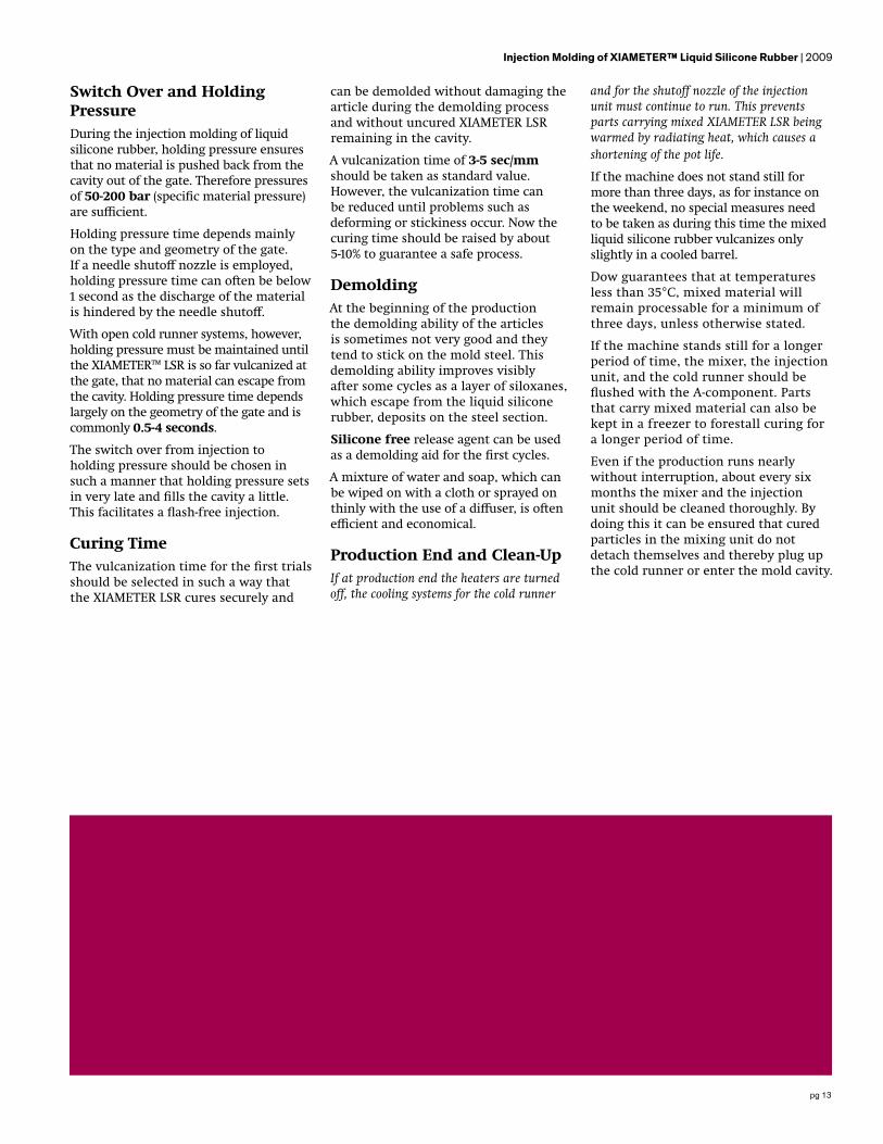
The composition of various silicones, as for the high-voltage technology for example, gives the advantage that the welding line of both materials is nearly as stable as the basic material.
Temperature PresetBefore operating the injection molding machine, all traces of mold protection spray or other rust preventatives must be thoroughly removed.
The injection unit and the cold runner should be cooled down to 20-25°.
According to experience, the first time a new tool is used, the temperature should be set to 180-190°C before beginning production.
Before starting the first cycles, the temperature should be within the desired temperature for a period of 10-20 minutes.If the mold is kept closed during the heating phase, the loss of heat at the parting line is significantly lower and thetemperature of the cavity surfaces rises uniformly with the mold temperature.
This guarantees the desired temperature in all mold parts, even those not heated directly.
With some machines the zero point of the mold can change because of the heat expansion. It makes sense, therefore, toadjust the zero point only at working temperature or to check it again when the working temperature has been reached.
Injection Stroke and FlowIf demolding renders it possible, it should be tried to underfill the first injection molded part so that an overloading can be avoided. In the following cycles
Starting the Production
the dosing volume can be gradually increased to the final shot size.
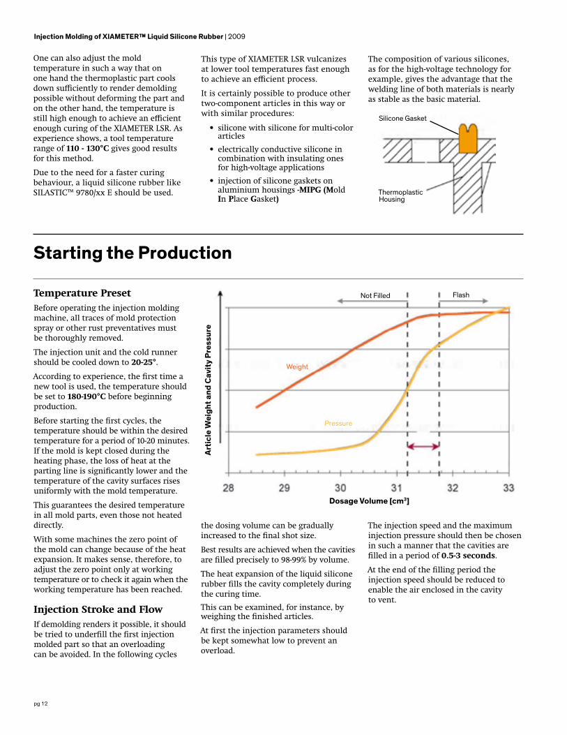
Best results are achieved when the cavities are filled precisely to 98-99% by volume.
The heat expansion of the liquid silicone rubber fills the cavity completely during the curing time.
This can be examined, for instance, by weighing the finished articles.
At first the injection parameters should be kept somewhat low to prevent an overload.
The injection speed and the maximum injection pressure should then be chosen in such a manner that the cavities arefilled in a period of 0.5-3 seconds.
At the end of the filling period the injection speed should be reduced to enable the air enclosed in the cavity to vent.
Art
icle
Wei
ght a
nd C
avit
y Pr
essu
re
Not Filled Flash
Weight
Pressure
Dosage Volume [cm3]
Injection Molding of XIAMETER™ Liquid Silicone Rubber | 2009
Silicone Gasket
ThermoplasticHousing
One can also adjust the mold temperature in such a way that on one hand the thermoplastic part cools down sufficiently to render demolding possible without deforming the part and on the other hand, the temperature is still high enough to achieve an efficient enough curing of the XIAMETER LSR. As experience shows, a tool temperature range of 110 - 130°C gives good results for this method.
Due to the need for a faster curing behaviour, a liquid silicone rubber like SILASTIC™ 9780/xx E should be used.
pg 13
Switch Over and Holding PressureDuring the injection molding of liquid silicone rubber, holding pressure ensures that no material is pushed back from the cavity out of the gate. Therefore pressures of 50-200 bar (specific material pressure) are sufficient.
Holding pressure time depends mainly on the type and geometry of the gate. If a needle shutoff nozzle is employed, holding pressure time can often be below 1 second as the discharge of the material is hindered by the needle shutoff.
With open cold runner systems, however, holding pressure must be maintained until the XIAMETER™ LSR is so far vulcanized at the gate, that no material can escape from the cavity. Holding pressure time depends largely on the geometry of the gate and is commonly 0.5-4 seconds.
The switch over from injection to holding pressure should be chosen in such a manner that holding pressure sets in very late and fills the cavity a little. This facilitates a flash-free injection.
Curing TimeThe vulcanization time for the first trials should be selected in such a way that the XIAMETER LSR cures securely and
can be demolded without damaging the article during the demolding process and without uncured XIAMETER LSR remaining in the cavity.
A vulcanization time of 3-5 sec/mm should be taken as standard value. However, the vulcanization time can be reduced until problems such as deforming or stickiness occur. Now the curing time should be raised by about 5-10% to guarantee a safe process.
DemoldingAt the beginning of the production the demolding ability of the articles is sometimes not very good and they tend to stick on the mold steel. This demolding ability improves visibly after some cycles as a layer of siloxanes, which escape from the liquid silicone rubber, deposits on the steel section.
Silicone free release agent can be used as a demolding aid for the first cycles.
A mixture of water and soap, which can be wiped on with a cloth or sprayed on thinly with the use of a diffuser, is often efficient and economical.
Production End and Clean-UpIf at production end the heaters are turned off, the cooling systems for the cold runner
and for the shutoff nozzle of the injection unit must continue to run. This prevents parts carrying mixed XIAMETER LSR being warmed by radiating heat, which causes a shortening of the pot life.
If the machine does not stand still for more than three days, as for instance on the weekend, no special measures need to be taken as during this time the mixed liquid silicone rubber vulcanizes only slightly in a cooled barrel.
Dow guarantees that at temperatures less than 35°C, mixed material will remain processable for a minimum of three days, unless otherwise stated.
If the machine stands still for a longer period of time, the mixer, the injection unit, and the cold runner should be flushed with the A-component. Parts that carry mixed material can also be kept in a freezer to forestall curing for a longer period of time.
Even if the production runs nearly without interruption, about every six months the mixer and the injection unit should be cleaned thoroughly. By doing this it can be ensured that cured particles in the mixing unit do not detach themselves and thereby plug up the cold runner or enter the mold cavity.
Injection Molding of XIAMETER™ Liquid Silicone Rubber | 2009

pg 14
Trouble Shooting for Injection Molding of XIAMETER LSR
1. Article is underfilled- Part is short- Uneven surface- Underweight part
Cause Solution
a) Injection speed or pressure is not optimal • Raise injection velocity and possibly injection pressure
b) Dosage insufficient • Enlarge dosing volume
c) Poor venting • (See Point 3) Bubbles/Burners
d) Tool temperature too high • Lower tool temperature
e) Switchover and holding pressure not correct
• Delay switchover• Increase holding pressure
f) Machine fault • Check radial screw clearance and non-return valve
g) Cold runner or sprue dimensions faulty
• Check sprue system for soiling or precured areas
• Check dimensions of sprue and possibly enlarge
h) Uneven filling of cavities • Balance runner and gat
i) Precuring in injection unit or supply lines • Clean system
Injection Molding of XIAMETER™ Liquid Silicone Rubber | 2009

pg 15
2. Flashing of mold - Silicone film at parting line
Cause Solution
a) Shot size too large • Reduce dosing volume• Check for even dosing volume
b) Injection speed or pressure is not optimal • Reduce injection velocity and possibly injection pressure
c) Switchover and holding pressure not correct • Set switch point earlier and reduce holdingpressure
d) Venting channels too big • Reduce size of vents
e) Tool temperature too low• Raise temperature and check on even
mold temperature• Check heaters and thermocouples
f) Tool damaged or soiled• Check parting lines and movable parts for
wear and repair or rework• Clean parting line
g) Clamping force too low • Raise clamping force or switch to larger machine if necessary
3. Bubbles / Burners - Blisters visible in finished parts- White edges
Cause Solution
a) Injection speed or pressure too high • Reduce injection velocity and possiblypressure
b) Tool temperature too high • Reduce tool temperature
c) Venting channels soiled or not properly dimensioned
• Clean mold• Deepen vents• Reduce clamping force
d) Vacuum insufficient• Check vacuum pump• Check gasket for defect spots• Prolong time for building up vacuum
e) Air in meter mixer • De-air the unit• Check gaskets
f) Uneven filling • Balance runner and gat
Injection Molding of XIAMETER™ Liquid Silicone Rubber | 2009

pg 16
4. Silicone not cured - Article sticks in the cavity- Article feels tacky
Cause Solution
a) Vulcanization time too short • Prolong vulcanization time
b) Tool temperature too low
• Raise temperature• Check heaters and thermocouples• Check if temperature is even• Shorten break time
c) Mixing proportion not 1:1• Check meter mixer for fluctuation of pressure• Clean supply lines and mixer from precured
particles and areas
d) Curing inhibited
• Check that no sulphur or tin are contaminating the XIAMETER LSR unit (occurs often when organic rubbers are produced close to XIAMETER LSR)
5. Scorch Precuring of the material during the injection process
- Part shows streaks- Strongly appearing flow lines- Orange skin
Cause Solution
a) Injection speed is too low • Raise injection velocity and possibly pressure
b) Tool temperature too high • Lower mold temperature and possibly cold runner temperature
6. Precured particles in finished article - Cured particles appearing in the part- Cured sprue visible in article
Cause Solution
a) Temperature of cold runner at injection point is not low enough
• Control or improve cooling of cold runner• Lower tool temperature at the gate
b) Material leaks from the injection point• Decompression of material in the cold runner
with open system insufficient• Shutoff needles have too much clearance
c) Precured particles are spooled out from the injection unit or mixer • Clean mixed material leading areas
Injection Molding of XIAMETER™ Liquid Silicone Rubber | 2009
pg 17
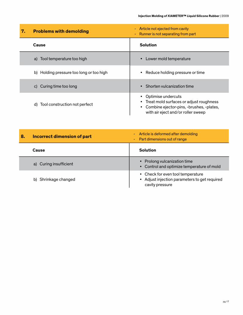
7. Problems with demolding - Article not ejected from cavity- Runner is not separating from part
Cause Solution
a) Tool temperature too high • Lower mold temperature
b) Holding pressure too long or too high • Reduce holding pressure or time
c) Curing time too long • Shorten vulcanization time
d) Tool construction not perfect
• Optimise undercuts• Treat mold surfaces or adjust roughness• Combine ejector-pins, -brushes, -plates,
with air eject and/or roller sweep
8. Incorrect dimension of part - Article is deformed after demolding- Part dimensions out of range
Cause Solution
a) Curing insufficient • Prolong vulcanization time• Control and optimize temperature of mold
b) Shrinkage changed• Check for even tool temperature• Adjust injection parameters to get required
cavity pressure
Injection Molding of XIAMETER™ Liquid Silicone Rubber | 2009

pg 18
9. Irregular cycle times - Varying cycle times during the production
Cause Solution
a) Dosing time varies and is sometimes longer than curing time
• Adjust pressure in the pumping unit evenly• Remove precured material from the mixer• Increase dosing speed• Optimise back pressure• Control hydraulic system of the machine• Check non-return valve
b) Injection time irregular
• Control injection parameters• Lower temperature of cold runner• Control for even dosing volume• Check non-return valve
Injection Molding of XIAMETER™ Liquid Silicone Rubber | 2009
10. Pot lifeMaterial cures in injection unit
- Starting difficulties after a longer production break- Longer injection and dosing times at production start
Cause Solution
a) Material in the mixer and the injection unit be-gins to cure
• Check cooling of injection unit• Spool unit with A-component before a
standstill of more than three days• Disconnect injection unit from the hot
mold even at short breaks• Continue cooling of cold runner after
switching off the tool heating
Cycle
maxt
mint
t

pg 19

In addition to the variety of XIAMETER™ materials showcased in this formulation guide, Dow also offers a wide variety of Dow specialty silicone material and service options as well as other silicon-based materials available to help you keep your innovative edge in the marketplace. Visit consumer.dow.com to learn more about the many additional silicone and silicon-based options available to you from Dow.
www.xiameter.com
Images: Cover – dow_40145791304, Page 3 – dow_40176190938, Page – 4 dow_40176178209, Page 11 – dow_40683052427
LIMITED WARRANTY INFORMATION – PLEASE READ CAREFULLY
The information contained herein is offered in good faith and is believed to be accurate. However, because conditions and methods of use of our products are beyond our control, this information should not be used in substitution for customer’s tests to ensure that our products are safe, effective and fully satisfactory for the intended end use. Suggestions of use shall not be taken as inducements to infringe any patent.
Dow’s sole warranty is that our products will meet the sales specifications in effect at the time of shipment.
Your exclusive remedy for breach of such warranty is limited to refund of purchase price or replacement of any product shown to be other than as warranted.
TO THE FULLEST EXTENT PERMITTED BY APPLICABLE LAW, DOW SPECIFICALLY DISCLAIMS ANY OTHER EXPRESS OR IMPLIED WARRANTY OF FITNESS FOR A PARTICULAR PURPOSE OR MERCHANTABILITY.
DOW DISCLAIMS LIABILITY FOR ANY INCIDENTAL OR CONSEQUENTIAL DAMAGES.
®™ Trademark of The Dow Chemical Company (“Dow”) or an affiliated company of Dow
© 2018 The Dow Chemical Company. All rights reserved.
30023848 Form No. 95-716-01 A