initial flight test of a ground deployed system for flying ... · initial flight test of a ground...
TRANSCRIPT

NASA Technical Memorandum 101700
.T
\
Initial Flight Test of a GroundDeployed System for FlyingQualities Assessment
M.F. Shafer, R. Koehler, E.M. Wilson, and D.R. Levy
(_tACA-TM-]OI700) I_!ITIAL FLIGHT TEST UF A
GROLJN_ DEPLOYED SYSTEM FOR FLYING -_UALITI_S
A_SESSM_NT (NASA) 10 I) CSCL _iC
,',,3/08
N91-15182
August 1989
I_IP_ANational Aeronautics and
Space Administration
https://ntrs.nasa.gov/search.jsp?R=19910005869 2018-07-28T02:02:47+00:00Z

NASATechnicalMemorandum101700
Initial Flight Test of a GroundDeployed System for FlyingQualities Assessment
M.F. Shafer, R. Koehler, E.M. Wilson, and D.R. LevyAmes Research Center, Dryden Flight Research Facility, Edwards, California
1989
National Aeronautics and
Space AdministrationAmes Research Center
Dryden Flight Research FacilityEdwards, California 93523-5000

w
INITIAL FLIGHT TEST OF A GROUND DEPLOYED SYSTEM
FOR FLYING QUALITIES ASSESSMENT
*<
Y
Mary E Shafer*NASA Ames Research Center
Dryden Flight Research Facility
Edwards, California
Ruthard Koehler**
DLR Institute for Flight Mechanics
Brannschweig, FRG
David R. Levyl
USAF Systems Command
DLR Institute for Flight Mechanics
Braunschweig, FRG
Edward M. Wilson t
Air Force Flight Test CenterEdwards AFB, California
Abstract
In order to provide a safe, repeatable, precise, high-
gain flying qualities task a ground deployed system was de-
veloped and tested at the NASA Ames Research Center's
Dryden Flight Research Facility. This system, the adapt-
able target lighting array system (ATLAS), is based on the
German Aerospace Research Establishment's ground attack
test equipment (GRATE). These systems provide a flying-
qualities task, emulating the ground-attack task with ground
deployed lighted targets. These targets light in an unpre-
dictable sequence and the pilot has to aim the aircraft at
whichever target is lighted. Two flight-test programs were
used to assess the suitability of ATLAS. The first program
used the United States Air Force (USAF) NT-33A vari-
ability stability aircraft to establish that ATLAS provided
a task suitable for use in flying qualities research. A head-
up display (HUD) tracking task was used for comparison.
The second program used the X-29A forward-swept wingaircraft to demonstrate that the ATLAS task was suitable
for assessing the flying qualities of a specific experimen-
tal aircraft. In this program, the ground-attack task was
used for comparison. All pilots who used ATLAS found
it to be highly satisfactory and thought it to be superior to
the other tasks used in flying qualities evaluations. They
have recommended that it become a standard for flying
qualities evaluations.
Nomenclature
AGL above ground level
ATLAS adaptable target lighting array system
DFRF Dryden Flight Research Facility
*Senior Aerospace Engineer. Associate Fellow, AIAA."*Senior Research Scientist.
t Captain, USAF.
tCaptain. USAF. Member, AIAA.
This paper is declared a work of the U.S. Government and is not subject
to copyright protection in the United States.
DLR
FDL
GRATE
HAVE ATLAS
HUD
KIAS
LAMARS
NASA
USAF
WRDC
German Aerospace Research Estab-
lishment, formerly DFVLR
Flight Dynamics Laboratory
ground attack test equipment
USAF Test Pilot School-sponsored
ATLAS test program
head-up display
knots indicated air speed
large amplitude multimode aerospaceresearch simulator
National Aeronautics and SpaceAdministration
United States Air Force
Wright Research and DevelopmentCenter
Introduction
To assess the flying qualities of an aircraft accuratelyrequires a high-gain, precise, repeatable, and well-defined
task. This task must be performed consistently by all pilots
involved in the test program and must have clearly defined
levels of satisfactory and acceptable performance. In addi-tion the task must be safe. It is also desirable for the task
to be realistic, resembling one that might be encountered in
operational flying.
A new approach to flying-qualities task definition was un-
dertaken at the German Aerospace Research Establishment
(DLR) Institute for Flight Mechanics in the early 1980s,
when a system known as the ground attack test equipment(GRATE) was developed and tested with success. 1,2.3 The
GRATE system emulates the ground-attack task with lighted
targets. The targets light in an unpredictable sequence and
the pilot has to aim the aircraft at whichever target is lit. This
task meets all the criteria--high-gain, repeatable, precise,

and safe. This task was also implemented in the large ampli-tude multimode aerospace research simulator (LAMARS) atWright-Patterson Air Force Base. 3,4
In 1987 NASA Ames Research Center's Dryden FlightResearch Facility (DFRF) developed a functional equiva-lent of the GRATE system for use at Edwards Air ForceBase. This system, known as the adaptable target fightingarray system or ATLAS, was initially flight-tested in a de-velopmental form in late 1988. The ATLAS is functionallyequivalent to the GRATE system but the implementation isquite different.
Four different fighter-type aircraft were flown using AT-LAS in two flight-test programs. The first of these pro-grams, known as HAVE ATLAS, was a senior project at theUSAF Test Pilot School. 5 This program established the pro-
cedures, including the definition of the task pattern, usinga T-38A and the USAF NT-33A variable-stability aircraft.The T-38A was used to establish the test procedure and trainthe pilots. Two tasks, ATLAS and a head-up display (HUD)tracking task, were evaluated with the NT-33A. In addition,the German pilot who flew evaluations using the GRATE
system flew the NT-33A using ATLAS.
A subsequent DFRF program used ATLAS to assess theflying qualities of the X-29A forward-swept wing aircraft.A TF-104G was also used for pilot familiarization. The fly-ing qualities of the X-29A had previously been evaluatedusing a simulated ground-attack task.
This paper briefly describes ATLAS and presents the re-suits of the two initial flight-test programs.
ATLAS Description
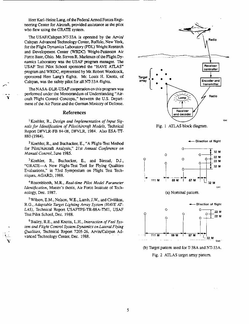
A block diagram of ATLAS is shown in Fig. 1. The sys-
tem is a stand-alone ground-based system consisting of areceiver-controller, an encoder and transmitter, and nine tar-
gets. Each target consists of a receiver, a decoder, and atarget lamp. The task is initiated when the pilot turns thesystem on using the aircraft radio. All of the target lampslight simultaneously for five seconds to allow the pilot toacquire the target an-ay and set up the task. The encoderthen transmits the identifier of a specific target from the pre-programmed sequence. When the target decoder receives itsidentifier it turns the target lamp on. The pilot then points
the aircraft at the lighted target, using the gunsight or I-Ibq3reticle. After a preset interval, a new target is designatedand the pilot again changes aim point. This continues until
the preprogrammed sequence ends. At this time the targetlamps light simultaneously for two seconds to show the pilotthe task is complete.
The receiver-controller, used to start the sequence, is de-signed to control runway lights at small general-aviation air-ports. The encoder is a microcomputer containing the pre-programmed target sequences. These sequences are sentto the transmitter. The transmitter then broadcasts the tat-
get command, which is received at each target. The mi-
crocomputer decoder lights the target lamp if its identifieris received.
The system deployed in this initial testing was a proto-type system. It was deployed in a remote location and usedportable generators for power. At the time of initial testing,seven targets were available.
The number of targets used in the preprogrammed se-quences and the length of time that the targets were lightedare predetermined, based on the type of aircraft and thespeed at which it flies. This is a safety-of-flight issue, asit is necessary to ensure that the sequence ends when thetest aircraft is still above a safe altitude.
The preprogrammed sequences are generated by twocomputer programs (provided by DLR) run on a mainframecomputer. The first program is used to define the size andshape of the target array, based on airspeed, initial and fi-nal altitudes, and dive angle. The second program gener-
ates the target sequences. These sequences, based on thenumber of targets used in the sequence, position of the tar-
gets, and length of time each target was to be lighted, wereoptimized for angular displacements in both the longitudinaland lateral-directional axes. The sequences are programmedinto the ATLAS encoder prior to deployment.
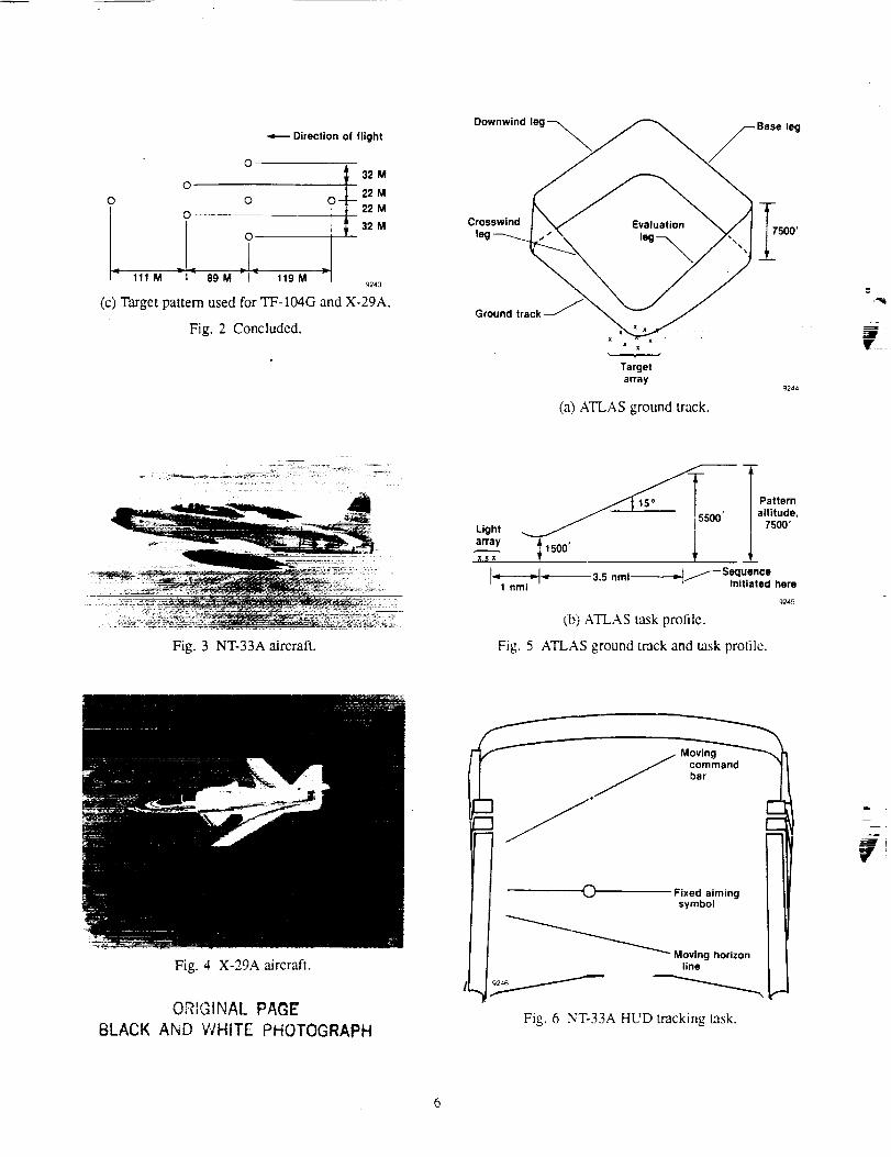
The nominal target pattern, shown in Fig. 2(a), is a dia-mond 350 m long and 120 m wide, using nine targets. Sinceonly seven targets were available at the time of testing, thepattern was initially modified, as shown in Fig. 2(b), for theHAVE ATLAS program. The pattern shown in Fig. 2(c) was
used to provide more lateral motion in the task for the X-29Aevaluations. The evaluation task started at 5500 ft above
ground level (AGL) and ended at 1500 ft AGL. The nom-inal dive angle was 15 ° and the airspeeds ranged from 300to 400 KIAS.
Flight-Test Procedure
Test Aircraft
The T-38A aircraft used has a HUD, but is otherwise un-modified. It has no instrumentation. The T-38A was used to
establish procedures, provide pilot proficiency, and evaluatethe initial usefulness of the ATLAS task. This aircraft was
not used for flying qualities evaluations. The T-38A wasflown at 400 KIAS.
The NT-33 aircraft (Fig. 3) is a two-seat, variable-stabilityaircraft with an analog-digital hybrid control system. This
aircraft, a flying-qualities research tool, has instrumenta-tion and a programmable HOD. This HOD has a computer-generated tracking task, which is used for flying-qualitiesevaluation. Another HUD display is a reticle, used for theATLAS task. Because it is a variable-stability aircraft, theflight characteristics of this aircraft can be varied, as se-lected by the safety pilot in the rear seat. The basic flightcharacteristics used in this program were chosen to providegood, Level 1 handling qualifies. This aircraft was flown at300 KIAS for.both the ATLAS and HOD tracking tasks.
F
2
_J
The TF-104G aircraft is an unmodified interceptor. The
aircraft, used only for pilot training and proficiency, has noHUD and no instrumentation. This aircraft was flown at
400 KIAS.
The X-29A aircraft (Fig. 4) is a single-seat experimen-
tal aircraft with a forward-swept wing. The aircraft, which
is extensively instrumented, has a highly augmented fly-by-
wire flight control system. Prior to the ATLAS program, an
extensive flying qualities study was performed with this air-
craft, using ground-attack and formation flight tasks. The
pilots characterized the simulated ground attack task as in-defined, not very consistent or repeatable, and Subject to
anticipation by the pilot. The ATLAS task was flown at
400 KIAS, and used the gunsight as the aiming device.
ATLAS Task
The task, which resembles the ground-attack task, is
shown in Fig. 5. The pilot flies around the ground track
shown and, when he rolls in on the evaluation leg, clicks
the microphone seven times to start the target sequence. Attl_ end of the target sequence he pulled up and climbed back
to the pattern altitude (7500 ft AGL) on the crosswind leg.
The time on the downwind leg is used to rate the aircraft and
complete the pilot comments. Desired and adequate perfor-mance for the task is identified in advance for each aircraft.
The pilots used the HUD reticle (for the T-38A and NT-33A)
or the gunsight (for the X-29A) as the aiming device.
The target pattern shown in Fig. 20a) was used with
the T-38A and NT-33A aircraft and the pattern shown
in Fig. 2(c) was used with the TF-104G and X-29A air-
craft. The wider target pattern was selected because prior
X-29A testing had indicated some deficiencies in the lateral-
directional flying qualities of the aircraft.
Target Sequences
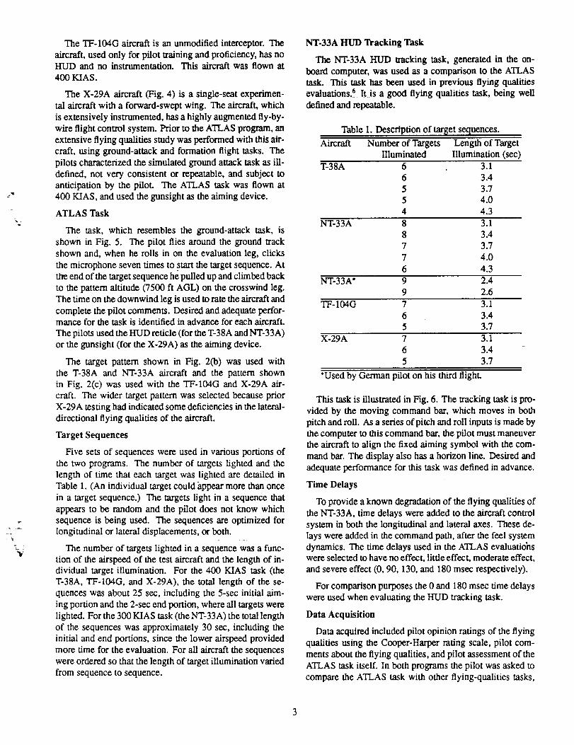
Five sets of sequences were used in various portions of
the two programs. The number of targets lighted and the
length of time that each target was lighted are detailed inTable 1. (An individual target could appear more than once
in a target sequence.) The targets light in a sequence that
appears to be random and the pilot does not know which
sequence is being used. The sequences are optimized for
longitudinal or lateral displacements, or both.
The number of targets lighted in a sequence was a func-
tion of the airspeed of the test aircraft and the length of in-dividual target illumination. For the 400 KIAS task (the
T-38A, TF-104G, and X-29A), the total length of the se-
quences was about 25 sec, including the 5-sec initial aim-
ing portion and the 2-sec end portion, where all targets were
lighted. For the 300 KIAS task (the NT-33A) the total length
of the sequences was approximately 30 sec, including theinitial and end portions, since the lower airspeed provided
more time for the evaluation. For all aircraft the sequences
were ordered so that the length of target illumination varied
from sequence to sequence.
NT-33A HUD Tracking Task
The NT-33A HUD tracking task, generated in the on-
board computer, was used as a comparison to the ATLAS
task. This task has been used in previous flying qualities
evaluations, 6 It is a good flying qualities task, being well
defined and repeatable.
Table I. Description of target sequences.
Aircraft Number of Targets Length of Target
Illuminated Illumination (sec)
T-38A 6 3.16 3.4
5 3.7
5 4.0
4 4.3
NT-33A 8 3.1
8 3.4
7 3.7
7 4.0
6 4.3
NT-33A* 9 2.4
9 2.6
TF-104G 7 3.1
6 3.4
5 3.7
X-29A 7 3.1
6 3.4
5 3.7
*Used by German pilot on his third flight.
This task is illustrated in Fig. 6. The tracking task is pro-
vided by the moving command bar, which moves in bothpitch and roll. As a series of pitch and roll inputs is made by
the computer to this command bar, the pilot must maneuver
the aircraft to align the fixed aiming symbol with the com-
mand bar. The display also has a horizon line. Desired and
adequate performance for this task was defined in advance.
Time Delays
To provide a known degradation of the flying qualities of
the NT-33A, time delays were added to the aircraft control
system in both the longitudinal and lateral axes. These de-
lays were added in the command path, after the feel system
dynamics. The time delays used in the ATLAS evaluationswere selected to have no effect, little effect, moderate effect,
and severe effect (0, 90, 130, and 180 msec respectively).
For comparison purposes the 0 and 180 msec time delays
were used when evaluating the HUD tracking task.
Data Acquisition
Data acquired included pilot opinion ratings of the flying
qualities using the Cooper-Harper rating scale, pilot com-
ments about the flying qualities, and pilot assessment of the
ATLAS task itself. In both programs the pilot was asked to
compare the ATLAS task with other flying-qualities tasks,

including the ground-attack task. In the NT-33A the pilotwas also asked to compare the ATLAS and HUD tasks.
Aircraft dynamic response data were available in the in-strumented aircraft and were collected for future analysis.Where available, HUD video tape or gun camera footagewas also collected. This footage was used by the flying qual-ities researcher and the pilot in post-flight discussion andreview of the task, the aircraft flying qualities, and the pilot
ratings and comments.
Results
The first part of the HAVE ATLAS program was initialflight testing, using the T-38A aircraft to establish the flight
pattern and procedures. To do this, four sorties, two by eachpilot, were flown. The pilots found the ATLAS task to bewell-defined and easily standardized.
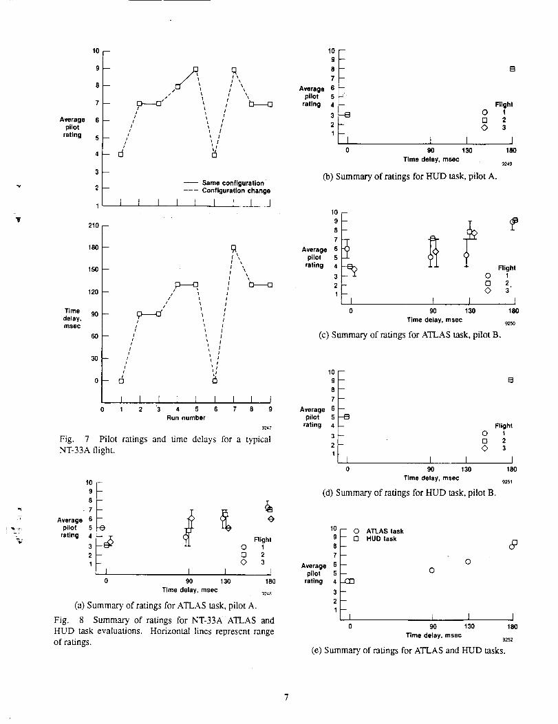
The second phase of the program was the NT-33A testing.An aircraft configuration with good flying qualities was se-lected and time delays of 0, 90, 130, and 180 msec wereadded to the flight-control system. When these four config-urations were flown using ATLAS, the changes in the flyingqualifies were perceptible. Figure 7 shows the pilot ratingand time delay, plotted against run number, for one typicalsortie. As can be seen, the increase in pilot rating correlateswith the increase in time delay as predicted. Six evaluationflights, three for each pilot, were flown in this phase. Fig-
ure 8 summarizes the results. The average pilot ratings areplotted against time delay for the ATLAS and HUD track-ing tasks in Figs. 80) and (b), respectively, for pilot A andin Figs. 8(c) and (d), respectively, for pilot B. The vertical
line indicates the range of pilot ratings. The wide range ofratings is not uncommon for degraded aircraft, particularly
for less experienced pilots. It can be seen that this range isreduced in later flights, showing the effect of learning. Fig-ure 8(e) shows the average ratings for both pilots for theATLAS and HUD tasks. The average ratings for the twotasks agreed well, validating the discrimination of the AT-LAS task.
The pilots found the ATLAS task to be well defined, withdesired and acceptable performance easily determined. TheHUD task was considered less desirable by the pilots, whocharacterized the task as being more like a video game than
areaqTsfi_tas_. Th_pii0ts thoughfthat tqaeir gain was higherfor the ATLAS task because the task was more demandingand more realistic. The pilots were unable to distinguish anydifferences in the length of time the targets were lighted inthe target sequences. The major recommendation made bythe pilots was that ATLAS be used in flying qualities investi-gations as well as being used to evaluate the flying qualitiesof specific aircraft.
The German test pilot who used GRATE also flew the NT-
33A using ATLAS. He said that GRATE and ATLAS werefunctionally equivalent and he was also able to distinguish
the various additional time delays. After his first flight in theNT-33A, this pilot thought the sequences used lighted thetargets too long, based on his experience with the GRATEsystem. His last flight used sequences with shorter times,which he found to be satisfactory.
Because the HAVE ATLAS program produced such posi-tive results and because the pilots had identified deficienciesin the simulated ground-attack task, the next use of ATLASwas to incorporate it into a DFRF flight-test program us-ing the X-29A aircraft. To familiarize the two X-29A pi-lots with the ATLAS location and procedures, a TF-104Gwas flown on one flight. The X-29A then flew using AT-LAS during three flights, with two pilots. The aircraft wasrated as Level 1 in pitch and Level 2 in roll, which cor-responds with ratings from other tasks. In post-flight de-briefings and flight reports, these pilots characterized the
task as extremely effective; being safe, repeatable, and pre-cise. They also thought that the resemblance to the ground-attack task decreased the time needed to become familiar
with the task and that the apparent randomness of the se-quences raised pilot gain and eliminated precognitive be-havior. Both pilots recommended that this system become a
standard for flying qualities evaluations, since it can be usedas a general task, and is not limited to ground-attack eval-uations. These pilots were also unable to distinguish anydifference in the length of time the targets were lighted.
Conclusions
Based on the results of these tests, ATLAS (like GRATE)
provides a safe, high-gain, precise, and repeatable task. Thepilot cannot anticipate the sequence and precognitive behav-ior does not occur. The test pilots who used ATLAS pre-ferred it to a variety of other tasks for flying qualities as-sessment, saying that the task was safe, well defined, andconsistent.
The results of the X-29A_gram demonstrated that al-
though ATLAS is a prototype system, it is suitable for oper-ational use.
Although this task resembles the ground-attack task, it isa more general task and is suitable for use with all aircraft,not just attack aircraft. However, the resemblance to the
ground-attack task provides realism and reduces the train-ing required by the pilot to a certain extent.
ATLAS is suitable both for assessing the flying qualitiesof a specific type of aircraft (i.e., specification compliance)and for general flying qualities research (i.e., using variable-stability aircraft).
Acknowledgements
These programs would not have been possible without theefforts and expertise of Mr. Glenn Bever, of the DFRF Fluidand Flight Mechanics Branch. He is responsible for the final
working version of ATLAS.
V
Herr Karl-Heinz Lang, of the Federal Armed Forces Engi-
neering Center for Aircraft, provided assistance as the pilot
who flew using the GRATE system.
The USAF/Calspan NT-33A is operated by the Arvin/
Calspan Advanced Technology Center, Buffalo, New York,for the Flight Dynamics Laboratory (FDL) Wright Research
and Development Center (WRDC) Wright-Patterson Air
Force Base, Ohio. Mr. Steven R. Markman of the Flight Dy-
namics Laboratory was the USAF program manager. The
USAF Test Pilot School sponsored the "HAVE ATLAS"
program and WRDC, represented by Mr. Robert Woodcock,
sponsored Herr Lang's flights. Mr. Louis H. Knotts, of
Calspan, was the safety pilot for all NT-33A flights.
The NASA-DLR-USAF cooperation on this program wasperformed under the Memorandum of Understanding "Air-
craft Flight Control Concepts," between the U.S. Depart-
ment of the Air Force and the German Ministry of Defense.
References
1Koehler, R., Design and Implementation of Input Sig-
nals for Identification of Pilot�Aircraft Models, Technical
Report DFVLR-FB 84-08, DFVLR, 1984. Also ESA-TT-880 (1984).
2Koehler, R., and Buchacker, E., "A Flight-Test Method
for Pilot/Aircraft Analysis," 21st Annual Conference onManual Control, June 1985.
3Koehler, R., Buchacker, E., and Biezad, DJ.,
"GRATE--A New Flight-Test Tool for Flying Qualities
Evaluations," in 73rd Symposium on Flight Test Tech-niques, AGARD, 1988.
4Rosenbleeth, M.R., Real-time Pilot Model Parameter
Identification, Master's thesis, Air Force Institute of Tech-
nology, Dec. 1987.
5Wilson, E.M., Nelson, W.E., Lamb, J.W., and Civilikas,
R.G., Adaptable Target Lighting Array System (HAVE AT-
LAS), Technical Report USAFrrPS-TR-88A-TM1, USAFTest Pilot School, Dec. 1988.
6Bailey, R.E., and Knotts, L.H., Interaction of Feel Sys-
tem and Flight Control System Dynamics on Lateral Flying
Qualities, Technical Report 7205-26, Arvin/Calspan Ad-
vanced Technology Center, Dec. 1988.
_ Radio
Target fe •array
I Rec fer/
• [ con ler
l• • I Encoder and I
• _ I transmitter ]
_Radio 92,o
Fig. 1 ATLAS block diagram.
111 M
Direction of flight
O
._._ 32 M0 0 22M
87 :M 32 M
724 l
(a) Nominal pattern.
!- 111 M
-,=----Direction of flight
0 0
0 _22 M
O[ _22 M
> _ 89M > _ 87M t-32M
Co) Target pattern used for T-38A and NT-33A.
Fig. 2 ATLAS target array pattern.
Direction of flight
O
O __32M
0 0 0 22 M
0 [ 22 M
32 M
g243
(c) Target pattern used for TF-104G and X-29A.
O
89 M 11g M
Fig. 2 Concluded.
Downwind _Base leg
Ground track J
Targetarray
_244
(a) ATLAS ground track.
mlF
Light
array
Fig. 5
=i 3.5 nmi----_-_ _-- Sequencenmi I _ initiated here
9245
(b) ATLAS task profile.
ATLAS ground track and task profile.
Fig. 4 X-29A aircraft.
ORIGINAL PAGE
BLACK AND WHITE PHOTOGRAPH
I I _ M_iViengh°riz°n
Fig. 6 NT-33A HUD tracking task.
'V.
-(
L
10--
Averagepilot
rating
I
/ t/
/-- /!
/
- /
L
I
qI "l
I \
t
t
I
t !
t 0
I I I 1
Same configuration
--- Configuration change
] I 1 I,I
210 --
Time
delay,msec
180
150
120
90
60
30
0
,p.-.--o/
ii
I
-/
!- /
/f
-- if
/- 6
/ ,I
1
I
tI
!
I
I
J
!
I
f
I
lI
1 I I I I I 1 I 10 1 2 "3 4 5 6 7 8 9
Run number
9247
Fig. 7 Pilot ratings and Lime delays for a typicalNT-33A flight.
Averagepilot
rating
10 -
9 -
8 -
• 7 --
6 -
5 -e4
32 --
t --
0 90 130
Time delay, msec
(a) Summary of ratings for ATLA.S task, pilot A.
Fig. 8 Summary of ratings for NT-33A ATLAS andHUD task evaluations. Horizontal lines represent rangeof ratings.
RightO 1
[3 23
I180
g248
10
g
8
7
Average 6pilot 5
rating 4
3
2
B
m
m
1 --J0
B
9O
Time delay, msec
O
mo
I130
(b) Summary of ratings for HUD task, pilot A.
Flight12
3
I180
9219
Averagepilot
rating
10
'I8
6
5
3
2
1
0
I I90 t 30
Time delay, msec
FlightO 1
O 2.O 3
]
(c) Summary of ratings for ATLAS task, pilot B.
18o
9250
10
9
8
7
Average 6pilot 5
rating 4
3
2
1
m
m
--t3
I0
O
Oo
I 19O 130
Time delay, msec
(d) Summary of ratings for HUD task, pilot B,
B
Flight123
I180
9251
Averagepilot
rating
10
9_ 08 -
7 -
6 -
5 -
4
3-2 -
I0
- O ATLAS taskHUD task
O
(e) Summary of ratings for ATLAS and HUD tasks.
90 130 180
Time delay, msec g252
t 1 I

Report Documentation Page
1. Report No.
NASA TM-10]700
2. Govmmment Accession No.
4. Title and Subtitle
Initial Flight Test of a Ground Deployed System
for Flying Qualifies Assessment
7. Author(sl
Mary F. Sharer, Ruthard Koehler,
Edward M. Wilson, and David R. Levy
9. Performing Organization Name and Address
NASA Ames Research Center
Dryden Flight Research Facility
P.O. Box 273, Edwards, CA 93523-5000
12. Spon_lodng Agency Nl_e"'and Address
National Aeronautics and Space Administration
Washington, DC 20546
3. Recipient'= Catalog No.
5. Report Date
August 1989
6. Performing Organization Code
8. Performing organization Report No.
H- 1554
10. Work unit No.
RTOP 505-61-71
11. Contract or Grant No.
13. Type of Report and Period Covered
Technical Memorandum
14.' Sp0r_nng Agency Code
15. Supplementary Notel
Prepared as AIAA paper 89-3359 for presentation at the AIAA Atmospheric Right Mechanics Conference,
Boston, Massachusetts, August 14-16, 1989.
16. Abstract
In order to provide a safe, repeatable, precise, high-gain flying qualities task a ground deployed sys-
tem was developed and tested at the NASA Ames Research Center's Dryden Right Research Facility. This
system, the adaptable target lighting array system (ATLAS), is based on the German Aerospace Research
Establishment's ground attack test equipment (GRATE). These systems provide a flying-qualities task, em-
ulating the ground-attack task with ground deployed lighted targets. These targets light in an unpredictable
sequence and the pilot has to aim the aircraft at whichever target is lighted. Two flight-test programs were
used to assess the suitability of ATLAS. The first program used the United States Air Force (USAF) NT-
33A variability stability aircraft to establish that ATLAS provided a task suitable for use in flying qualities
research. A head-up display (HUD) tracking task was used for comparison. The second program used the
X-29A forward-swept wing aircraft to demonstrate that the ATLAS task was suitable for assessing the flying
qualities of a specific experimental aircraft. In this program, the ground-attack task was used for compari-
son. All pilots who used ATLAS found it to be highly satisfactory and thought it to be superior to the other
tasks used in flying qualifies evaluations. They have recommended that it become a standard for flying
qualities evaluations.
17. Key Words (Suggested by Author(s))
ATLAS
Flying qualitiesGRATE
18. Distribution Statement
Unclassified -- Unlimited
19. Security Classif. (of this report) 20, Security Classif. (of this page) 21. No. of pages
Unclassified Unclassified 7
_IASA FORM 1626 OCT 86
*For sale by the National Technical Information Service, Springfield, VA 22161-2171.
Subject category 0822. Price
A02