information technology services - university of tasmania · information technology services ... 3...
TRANSCRIPT
.
InformationTechnologyServices
TelecommunicationsCablingSpecificationandStandard
V2.1
VER Issue Date Description Prep By Chk’d By Reason for Revision
1.0 01/11/09 Draft – issues for review J.McGee J.Miezitis Initial release
1.1 Draft – issued for review J.McGee J.Miezitis Incorporate review comments
1.2 26/08/11 Draft – issued for review R.Samson A.F.Walch Incorporate minor corrections and reformat
1.3 15/11/11 Draft – issued for review R.Samson A.F.WalchJ.Miezitis
Minor corrections and updated Appendices for Rack Layouts
2.0 17/10/14 Draft – issued for review R.Page A.F.Walch Major updates to nominated products & design of Telecommunications Spaces
2.1 14/11/14 Draft – Issued for review R.Page A.F.Walch Minor corrections to nominated products

TABLE OF CONTENTS
2 IT Services | Telecommunications Cabling Specification & Standard v.2.1 | University of Tasmania | Page 2 of 54
1 OVERVIEW ........................................................................................................................................... 5
1.1 PURPOSE ................................................................................................................................................... 5
1.2 DOCUMENT CONTROL ................................................................................................................................. 5
1.3 SCOPE ...................................................................................................................................................... 5
1.4 QUERIES AND CLARIFICATIONS ....................................................................................................................... 6
2 REFERENCE DOCUMENTS & DEFINITION OF TERMS ............................................................................... 7
2.1 AUSTRALIAN STANDARDS AND INDUSTRY CODES OF PRACTICE ............................................................................. 7
2.2 REGULATORY STANDARDS ............................................................................................................................. 7
2.3 PRIMARY AUSTRALIAN STANDARDS ................................................................................................................ 7
2.4 OTHER NATIONAL STANDARDS ...................................................................................................................... 8
2.5 OTHER AS/ACIF STANDARDS ....................................................................................................................... 8
2.6 OTHER STATUTORY CODES OF PRACTICE AND REGULATIONS ............................................................................... 8
2.7 UTAS REGULATIONS ................................................................................................................................... 9
2.8 DEFINITION OF TERMS ............................................................................................................................... 10
2.9 GLOSSARY OF ACRONYMS ........................................................................................................................... 11
3 UTAS COMMUNICATIONS SYSTEMS .................................................................................................... 12
3.1 GENERAL ................................................................................................................................................. 12
3.2 CONVERGED IP NETWORK CABLING OVERVIEW .............................................................................................. 12
3.3 LEGACY VOICE SERVICE CABLING OVERVIEW .................................................................................................. 13
4 NOMINATED PRODUCTS ..................................................................................................................... 14
4.1 GENERAL ................................................................................................................................................. 14
4.2 STRUCTURED CABLING SYSTEM PRODUCTS .................................................................................................... 14
4.3 PANDUIT WARRANTY ................................................................................................................................ 15
4.4 OTHER VENDOR EQUIPMENT ...................................................................................................................... 15
4.5 SUBMISSION OF SAMPLES FOR APPROVAL ...................................................................................................... 15
5 CONTRACTOR CERTIFICATIONS AND OBLIGATIONS ............................................................................. 16
5.1 ACMA REGISTRATION ............................................................................................................................... 16
5.2 PANDUIT CERTIFICATION ............................................................................................................................ 16
5.3 CONTRACTOR’S PROJECT MANAGER ............................................................................................................. 16
5.4 CONTRACTOR’S PROJECT SUPERVISOR ........................................................................................................... 16
5.5 CONTRACTOR ON‐SITE OBLIGATIONS............................................................................................................ 17
5.6 PANDUIT INSTALLATION REQUIREMENTS ....................................................................................................... 17
5.7 COORDINATION WITH OTHER WORKS ........................................................................................................... 17
5.8 LIAISON WITH UTAS COMMERCIAL SERVICES & DEVELOPMENT ......................................................................... 17
5.9 LIAISON WITH EXTERNAL AUTHORITIES .......................................................................................................... 17
5.10 WORK ON SITE ........................................................................................................................................ 18
5.11 SITE INSPECTION ....................................................................................................................................... 18
5.12 EXTERNAL CIVIL WORKS ............................................................................................................................. 18
5.13 REINSTATEMENT OF PENETRATIONS .............................................................................................................. 18
5.14 WORK IN UTAS NON‐STANDARD AND DESIGNATED “RESTRICTED” AREAS .......................................................... 18
5.15 MINOR MATERIALS, FITTINGS AND CONSUMABLES .......................................................................................... 19
6 UTAS STRUCTURED CABLING SYSTEM SPECIFICATIONS ....................................................................... 20
6.1 STRUCTURED CABLING SYSTEMS (SCS) ......................................................................................................... 20
6.2 SCS DIMENSIONING AND CONFIGURATIONS ................................................................................................... 21
TABLE OF CONTENTS
3 IT Services | Telecommunications Cabling Specification & Standard v.2.1 | University of Tasmania | Page 3 of 54
7 CABLING SPECIFICATIONS FOR NEW WORKS ....................................................................................... 22
7.1 CABLES – GENERAL ................................................................................................................................... 22
7.2 HORIZONTAL CABLING FOR PERMANENT LINK ................................................................................................. 22
7.3 HORIZONTAL CABLING FOR CORDS ............................................................................................................... 22
7.4 BUILDING BACKBONE CABLES ...................................................................................................................... 22
7.5 CAMPUS BACKBONE CABLES ....................................................................................................................... 22
7.6 TERMINATIONS SPECIFICATIONS FOR NEW CABLING WORK ................................................................................ 23
7.7 DISTRIBUTORS, PATCH PANELS AND CABLE MANAGEMENT ............................................................................... 25
7.8 OVERVOLTAGE PROTECTION ........................................................................................................................ 25
7.9 EARTHING CABLE SCREENS .......................................................................................................................... 25
8 UTAS SCS PATHWAYS SPECIFICATIONS ............................................................................................... 27
8.1 PATHWAY, ENCLOSURE AND SPACE DESIGN ................................................................................................... 27
8.2 PATHWAY ROUTING AND SEPARATION FROM POWER SERVICES ......................................................................... 27
8.3 INTRA‐BUILDING PATHWAYS ....................................................................................................................... 27
8.4 CAMPUS PATHWAYS .................................................................................................................................. 28
9 TELECOMMUNICATIONS SPACES ........................................................................................................ 29
9.1 GENERAL ................................................................................................................................................. 29
9.2 ROOM DIMENSIONS .................................................................................................................................. 30
9.3 ROOM ACCESS & SECURITY ........................................................................................................................ 31
9.4 SIGNAGE ................................................................................................................................................. 31
9.5 LIGHTING & ROOM FINISHES ....................................................................................................................... 31
9.6 POWER ................................................................................................................................................... 32
9.7 ROOM COOLING & VENTILATION ................................................................................................................. 32
9.8 DESIGN OF TELECOMMUNICATIONS ROOMS ................................................................................................... 32
9.9 ENCLOSURES AND RACKS ............................................................................................................................ 32
10 UTAS SCS – INSTALLATION REQUIREMENTS .................................................................................... 34
10.1 GENERAL INSTALLATION REQUIREMENTS ....................................................................................................... 34
10.2 INSTALLATION OF CABLING .......................................................................................................................... 34
10.3 INSTALLATION OF CABLE PATHWAYS & CABLE SUPPORT SYSTEMS ...................................................................... 35
10.4 CONNECTION TO CARRIER NETWORK TERMINATION DEVICES ............................................................................ 37
10.5 NETWORK BOUNDARY ............................................................................................................................... 38
11 UTAS SCS LABELLING REQUIREMENTS ............................................................................................. 39
11.1 LABELLING ............................................................................................................................................... 39
11.2 UTAS SCS LABELLING ............................................................................................................................... 39
12 TESTING AND INSPECTION .............................................................................................................. 40
12.1 GENERAL ................................................................................................................................................. 40
12.2 TESTING .................................................................................................................................................. 40
12.3 TEST RESULTS ........................................................................................................................................... 40
12.4 INSPECTION ............................................................................................................................................. 41
13 CABLING ADMINISTRATION ............................................................................................................ 42
13.1 REFERENCE STANDARDS AND DOCUMENTATION FOR THIS SECTION ..................................................................... 42
13.2 TCA1 FORM ............................................................................................................................................ 42
13.3 CONSTRUCTION DOCUMENTATION ............................................................................................................... 42
13.4 HANDOVER DOCUMENTATION ..................................................................................................................... 42
TABLE OF CONTENTS
4 IT Services | Telecommunications Cabling Specification & Standard v.2.1 | University of Tasmania | Page 4 of 54
14 UTAS SCS – COMMISSIONING AND ACCEPTANCE ............................................................................ 43
14.1 COMMISSIONING ...................................................................................................................................... 43
14.2 SITE RESTORATION .................................................................................................................................... 43
14.3 PANDUIT ACCEPTANCE AND PANDUIT WARRANTY ........................................................................................... 43
14.4 UTAS ACCEPTANCE FOR PRACTICAL COMPLETION........................................................................................... 43
14.5 FINAL ACCEPTANCE ................................................................................................................................... 43
APPENDIX A – LABELLING STANDARDS ....................................................................................................... 44
LABELLING THE RACK END ....................................................................................................................................... 44
LABELLING THE WALL PLATE .................................................................................................................................... 45
CABLE NUMBER & RACK POSITION REFERENCE TABLE .................................................................................................. 46
APPENDIX B – RACK LAYOUTS .................................................................................................................... 47
SINGLE RACK LAYOUT ............................................................................................................................................. 47
DUAL RACK LAYOUT ............................................................................................................................................... 48
SINGLE RACK FLOOR PLAN ...................................................................................................................................... 49
DUAL RACK FLOOR PLAN ........................................................................................................................................ 50
TRIPLE RACK FLOOR PLAN ....................................................................................................................................... 51
APPENDIX C – CABLE ROUTING ................................................................................................................... 52
CABLE ROUTING BETWEEN RACKS ............................................................................................................................ 52
CABLE ROUTING BETWEEN SWITCHES AND PATCH PANELS............................................................................................. 53
APPENDIX D ‐ COLOUR CODE CHART .......................................................................................................... 54
INTRODUCTION
5 IT Services | Telecommunications Cabling Specification & Standard v.2.1 | University of Tasmania | Page 5 of 54
1 Overview 1.1 Purpose The purpose of this document is as the general Specification and Statement of Requirements for all work
undertaken by Contractors within the University of Tasmania (UTAS) campuses and premises involved in
the design, supply, construction, installation and commissioning of telecommunications cabling systems,
herein called Structured Cabling Systems (SCS). It includes works for new buildings, modifications and
extensions to existing buildings and for any external campus area telecommunications cabling. In addition
to this general Specification and Statement of Requirements, each Contract shall also contain the specific
quantities, locations, routes and particular options for the telecommunications cabling works under that
contract.
This document also serves as the Specification for all planning, design and minor works and/or
modifications involving or impacting on telecommunications cabling systems undertaken by UTAS staff,
consultants, service providers and period contractors.
The specifications within this document are designed to be the minimum standard of UTAS SCS. They are
to be viewed as general requirements and specifications to allow for adjustment in today’s ever growing
and changing telecommunications industry. These specifications may be reviewed and modified by
Information Technology Services (ITS) to accommodate specific space requirements as well as any
functional or special design needs.
Wiring specifications as well as those specifications designed to support wiring are constantly changing as
per the dynamic changes of industry and networking standards evolve. All contractors will be required to
receive approval from ITS before commencing an installation to ensure that all the current media types,
systems and installation standards are being followed.
1.2 Document Control The current approved version of this document is that digital version at
http://www.utas.edu.au/it/communication‐technologies/standards. Any printed version of this document
will be out‐of‐date on the date of its printing and will not be considered the latest version past the date it
was printed. It is the responsibility of the contractor to ensure that the current version is being used.
1.3 Scope The scope of work covered document includes the technical specifications and requirements for UTAS
structured cabling systems;
Product selection;
Contractor certification and obligations;
Systems dimensioning for planning and design;
Contractor requirements for construction, installation, labelling, testing and commissioning;
Inspection and acceptance by UTAS; and
Contract administration and documentation.
1.3.1 In Scope
All UTAS owned SCS which are used to provide telecommunications and networking infrastructure to UTAS
staff, student and IT systems, including data, voice, video, audio visual and converged communications
services, are within scope.
INTRODUCTION
6 IT Services | Telecommunications Cabling Specification & Standard v.2.1 | University of Tasmania | Page 6 of 54
SCS include optical fibre cables and balanced copper cables supporting information transmission at the
physical layer (OSI Layer 1) within the UTAS Information Infrastructure; the cable pathways supporting
these cables; and the enclosures and dedicated spaces used for terminating, interconnecting and patching
these cables to active telecommunications equipment and systems.
The UTAS Information Infrastructure physical layer includes Campus cabling systems, Building cabling
systems, Floor cabling systems, and any inter‐campus cabling systems owned and managed by UTAS.
1.3.2 Out of Scope
UTAS cable systems which are not within scope include:
Fire monitoring and alarming systems with independent cabling plant;
Building Management Systems with independent cabling plant;
Security access and monitoring systems independent cabling plant;
Dedicated Security coaxial cable CCTV systems;
Dedicated coaxial cable TV reticulation systems;
Non‐Internet Protocol (IP) proprietary audio‐visual systems, such as intra‐room AMX cabling;
Dedicated special access systems, such as in‐theatre induction loops for the hearing impaired;
Carrier owned or other 3rd Party cable systems and cable plant transiting UTAS campuses (and
including AARNet cabling systems);
Earthing systems to which the UTAS SCS earthing conductors and reference points may connect
to.
1.4 Queries and Clarifications Any queries or clarifications on the contents of this document or requirements from the specifications and
requirements within this document can be sought from:
E‐mail: [email protected]
Telephone: +61 3 6226 1532

REFERECNCES & DEFINITIONS
7 IT Services | Telecommunications Cabling Specification & Standard v.2.1 | University of Tasmania | Page 7 of 54
2 Reference Documents & Definition of Terms 2.1 Australian Standards and Industry Codes of Practice The Telecommunications Cabling Provider Rules 2000 (CPRs) regulate the cabling industry and ensure that
minimum cabling requirements are in place to promote safety and maintain network integrity. ACMA and
Standards Australia Communications Cabling Committee have produced a Handbook, called the
Communications Cabling Manual, which incorporates the CPRs, identifies the legal and regulatory
obligations under the Telecommunications Act, 1997, and includes the minimum set of Regulatory
Standards developed by the Industry and the applicable Australian Standards.
Where appropriate, and without introducing unnecessary duplication, the specifications and requirements
within this document reference the CPRs, Regulatory Standards and Australian Standards which
contractors are required to meet and/or comply with.
2.2 Regulatory Standards The key Australian Codes of Practice applicable to all work performed by Contractors under this
Specification and Statement of Requirements are:
Standards/Specification or Technical Bulletin Document Description
Telecommunications Cabling Provider Rules,
2000.
ACMA cabling industry regulations.
AS/CA S009:2013 Installation requirements for customer cabling (“Communications
Wiring Rules”).
AS/CA S008:2010 Requirements for customer Cabling Products
2.3 Primary Australian Standards The key Australian Standards applicable to all work performed by contractors under this Specification and
Statement of Requirements are:
Standards/Specification or Technical Bulletin Document Description
AS/NZS 3080:2003 Telecommunications installations ‐ Generic cabling for commercial
premises.
AS/NZS 3084:2003 Telecommunications installations ‐ Pathways and spaces
(incorporating Amendment 1:2007).
AS/NZS 3085.1:2004 Telecommunications installations ‐ Administration of
communications cabling systems ‐ Basic requirements.
AS/NZS IEC 61935.1:2006 Testing of balanced communication cabling in accordance with
ISO/IEC 11801 – Installed cabling.
AS/NZS IEC 61935.2:2006 Testing of balanced communication cabling in accordance with
ISO/IEC 11801 ‐ Patch Cords and work area Cords.
AS/NZS ISO/IEC 14763.3:2007 Telecommunications installations ‐ Implementation and operation of
customer premises cabling ‐ Testing of optical fibre.

REFERECNCES & DEFINITIONS
8 IT Services | Telecommunications Cabling Specification & Standard v.2.1 | University of Tasmania | Page 8 of 54
2.4 Other National Standards Other Australian Standards applicable to specific works performed by Contractors under this Specification
and Statement of Requirements include:
Standards/Specification or Technical Bulletin Document Description
AS 1049.1:2008 Telecommunication cables—Insulation, sheath and jacket –
Materials.
AS 1049.2:2008 Telecommunication cables—Insulation, sheath and jacket – Test
Methods.
AS/NZS 2211.1:2004 Safety of laser products – Equipment classification, requirements and
user’s guide (IEC 60825‐1:2001, MOD.).
AS/NZS 2211.2: 2006 Laser safety – Safety of optical fibre communication systems (OFCS).
AS/NZS 2648.1:1995 Underground marking tape – Non‐detectable tape.
AS/NZS 3000:2007 Electrical installations (known as the Australian/New Zealand Wiring
Rules).
AS/NZS 4117:1999 Surge protective devices for telecommunication applications.
AS 4262.1‐1995 Telecommunications over‐voltages – Protection of persons.
AS 4262.2‐1999 Telecommunications overvoltage – Protection of equipment.
AS 60529‐2004 Degrees of protection provided by enclosures (IP Code).
AS/NZS 60950.1:2003 Information technology equipment ‐ Safety ‐ General requirements.
Note: within AS/CA S008:2013 and AS/ACIF S008:2010 there are additional Australian and International
Standards upon which these regulatory Codes of Practice refer.
2.5 Other AS/ACIF Standards Standards/Specification or Technical Bulletin Document Description
AS/ACIF S006:2001 Requirements for Customer Equipment, operating in the voiceband,
for connection to the non‐switched Telecommunications Network.
AS/ACIF S043 Requirements for Customer Equipment for connection to a metallic
local loop interface of a Telecommunications Network.
AS/ACIF S043.1:2003 Part 1: General.
AS/ACIF S043.2:2005 Part 2: Broadband.
AS/ACIF S043.3:2001 Part 3: DC, low frequency AC and voiceband.
2.6 Other Statutory Codes of Practice and Regulations The work performed by Contractors under this Specification and Statement of Requirements shall comply
with all relevant Tasmanian Acts and legislation.

REFERECNCES & DEFINITIONS
9 IT Services | Telecommunications Cabling Specification & Standard v.2.1 | University of Tasmania | Page 9 of 54
2.7 UTAS Regulations Cabling system works shall be carried out in accordance with UTAS standards and specifications identified
in tender or contract documents.
For building design requirements please refer to the CS&D Design Requirements documentation.
In the event of conflict between departmental standard or specification and other regulations, codes or
standards the order of precedence shall be:
1) Statutory Codes and Regulations
2) Mandatory Codes and Standards (e.g. AS/ACIF S009)
3) Departmental Standards or Specification with the tender or contract
4) Panduit installation practices and standards
5) This specification
6) Referenced Australian and International Standards
Where, for purposes of design or installation, the standards and specifications detailed in this document
do not offer the most appropriate solution, an exemption must be sought from the ICT Executive.
Exemptions may only be granted by the Chief Information Officer or a duly appointed delegate. Requests
for exemptions must be in writing and any subsequent approval or rejection must also be in writing. No
variation from the standards and specifications detailed in this document is allowable without formal
exemption. Notification of approval for any exemption must include notification of the potential for
product and application warranties becoming void.
REFERECNCES & DEFINITIONS
10 IT Services | Telecommunications Cabling Specification & Standard v.2.1 | University of Tasmania | Page 10 of 54
2.8 Definition of Terms Balanced Copper Cable ‐ is a cable made up of one or more copper (solid or stranded) symmetrical elements. In particular, three Balanced Copper Cables are specified in this document: Category 6 for Legacy Voice Services and typically 100 pair tie cables; Category 6 for standard Horizontal Channel cabling; and Category 6A for specialised 10 Gbps Horizontal Channel cabling requirements.
Building Backbone Cable ‐ is cable which connects a Building Distributor to a Floor Distributor.
Building Distributor ‐ is the Distributor in which Building Backbone and Campus Backbone Cables terminate, cross connect and interconnect.
Cable Cross Connect ‐ is a mechanism via (patch) Cords and within cable connecting hardware for flexible connections between the fixed termination of one cable subsystem and the fixed termination of other cable subsystems or to the active equipment within the Distributor.
Cable Interconnect ‐ is a mechanism within cable connecting hardware for direct connections (without the use of Cords) between the fixed termination of cable subsystems and the fixed termination of other cable subsystems or to the active equipment within the Distributor.
Cabling Product ‐ is a passive device including cables, cable connecting hardware and surge suppression devices, making up the cabling elements of the SCS.
Cabling Work ‐ is work undertaken on the SCS under the requirements and specifications of this document.
Cabling Service Operator ‐ is defined by the Telecommunications (Section of the Telecommunications Industry) Determination 2003 (No. 1) and includes businesses that arrange for the installation, connection or maintenance of customer cabling. In this document, the Cabling Service Operator is the Contractor.
Campus Backbone Cable ‐ is outdoor cable which connects the Campus Distributor to the Building Distributors.
Campus Distributor ‐ is the Distributor in which Campus Backbone Cables terminate, cross connect and interconnect, and where any external Carrier or private wide area cabling terminates. In the case of Carrier terminations, it defines the Network Boundary.
Category 6 (Cat 6) ‐ is unshielded twisted pair (UTP), Balanced Copper Cable which meets the performance specifications for ISO/IEC 11801:2002 Class E for up to 250 MHz. It is used by UTAS for Horizontal Channel cables carrying 1 Gbps Ethernet, and for Legacy Voice Service analogue VF services.
Category 6A (Cat 6A) ‐ is unshielded twisted pair (UTP), Balanced Copper Cable which meets the performance specifications for ISO/IEC 11801:2002 (Amendment 2) Class EA for up to 500 MHz. It is used by UTAS for Horizontal Channel cables carrying 10 Gbps Ethernet.
Cord ‐ is flexible balanced copper or optical fibre cable of length less than 10 metres which is terminated at both ends and contains one termination. Cords are used within Distributors for cross connect patching and within the work area for connecting network connecting equipment to TOs.
Floor Distributor ‐ is the Distributor in which Building Backbone and Horizontal Cables terminate, cross connect and interconnect.
Horizontal Cable ‐ is the cable connecting the Floor Distributor to a TO.
Horizontal Channel ‐ is the segment of the Horizontal Cable subsystem between the active equipment terminal (port) in the Floor Distributor and the active network connecting terminal in the work area. It includes the Horizontal cabling Permanent Link, any consolidation points, the TO, the RJ45 patch ports with the Patch Panel(s), patch Cords and work area Cords used in the end‐to‐end transmission path. The Horizontal Channel length is up to 100 metres.

REFERECNCES & DEFINITIONS
11 IT Services | Telecommunications Cabling Specification & Standard v.2.1 | University of Tasmania | Page 11 of 54
Network Boundary ‐ is the boundary point between UTAS and a Telecommunications Carrier for the purposes of identifying the UTAS SCS.
Open Cabling Work ‐ is any type of customer Cabling Work (including aerial or underground Cabling Work on public or private property) in which the customer cabling that is used terminates at the Network Boundary at a socket, a network termination device or a distributor, such as a Floor Distributor, Building Distributor or a Campus Distributor of four or more pairs.
Patch Panel ‐ is an assembly of multiple connectors to accommodate the use of Cords for cross connections.
Permanent Link ‐ is the transmission link between a TO and the Floor Distributor.
Pigtail ‐ is a length of optical fibre cordage with a connector fitted at one end only and with the other end free for fusion splicing.
Telecommunications Outlet (TO) ‐ is a fixed connecting device within the work area for connecting network connecting equipment to the SCS.
2.9 Glossary of Acronyms ACIF Australian Communications Industry Forum
ACMA Australian Communications and Media Authority
AS/NZS Australian and New Zealand Standard
AARNet Australian Academic Research Network
Cat 5 Category 5
Cat 6 Category 6
Cat 6A Category 6A
CCTV closed circuit television
CPR Telecommunications Cabling Provider Rules
Gbps Gigabits per second
IEEE Institute of Electrical and Electronics Engineers
IP Internet Protocol
kV kilovolt
m metre
mm millimetre
MHz Mega Hertz
OM optical multimode
OS optical single mode
OSI Open Systems Interconnection reference model
PABX private automatic branch exchange
RU rack unit
SCS Structured Cabling System
TO Telecommunications outlet
UTAS University of Tasmania
UTP unshielded twisted pair
WAP Wireless Access Point
COMMUNICATIONS SYSTEMS
12 IT Services | Telecommunications Cabling Specification & Standard v.2.1 | University of Tasmania | Page 12 of 54
3 UTAS Communications Systems 3.1 General The UTAS Communications System is an integrated telecommunications network supporting all data, voice,
video and converged communications services, providing both fixed and mobile access, and with Wide
Area Network (WAN) links interconnecting all campuses and sites. The converged environment is based
on IP‐over‐Ethernet technology. There is also a legacy PABX network which is gradually being replaced by
IP telephony as the PABX elements reach end of life. The network structure includes a core network and
an access network. The access network generally includes a distribution layer and an edge layer, although
for smaller locations these functions are merged. The core network’s physical layer for each campus is a
meshed optical fibre network supporting 10 Gigabit per second Ethernet. Each building within a campus
is connected to the core network via optical fibre links, generally via redundant physically separated links
and supporting either 10 Gigabit per second or 1 Gigabit per second Ethernet. The access network is
progressively moving to 1 Gigabit per second Ethernet connections to the desktop. WAN connections
between the main campuses form a 1 Gigabit per second MPLS network.
The UTAS Communications System is centrally managed by the Infrastructure and Operations section of
the Information Technology Resources (ITS) business unit of UTAS.
ITS is responsible for asset management of the physical telecommunications infrastructure which makes
up the UTAS Structured Cabling Systems.
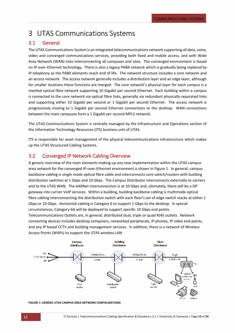
3.2 Converged IP Network Cabling Overview A generic overview of the main elements making up any new implementation within the UTAS campus
area network for the converged IP‐over‐Ethernet environment is shown in Figure 1. In general, campus
backbone cabling is single mode optical fibre cable and interconnects core switch/routers with building
distribution switches at 1 Gbps and 10 Gbps. The Campus Distributor interconnects externally to carriers
and to the UTAS WAN. The AARNet interconnection is at 10 Gbps and, ultimately, there will be a SIP
gateway into carrier VoIP services. Within a building, building backbone cabling is multimode optical
fibre cabling interconnecting the distribution switch with each floor’s set of edge switch stacks at either 1
Gbps or 10 Gbps. Horizontal cabling is Category 6 to support 1 Gbps to the desktop. In special
circumstances, Category 6A will be deployed to support specific 10 Gbps end points.
Telecommunications Outlets are, in general, distributed dual, triple or quad RJ45 outlets. Network
connecting devices includes desktop computers, networked peripherals, IP phones, IP video end points,
and any IP based CCTV and building management services. In addition, there is a network of Wireless
Access Points (WAPs) to support the UTAS wireless LAN.
FIGURE 1: GENERIC UTAS CAMPUS AREA NETWORK CONFIGURATIONS
COMMUNICATIONS SYSTEMS
13 IT Services | Telecommunications Cabling Specification & Standard v.2.1 | University of Tasmania | Page 13 of 54
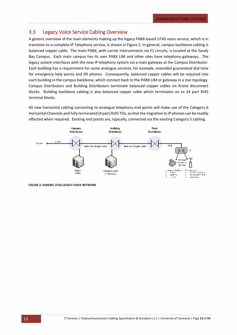
3.3 Legacy Voice Service Cabling Overview A generic overview of the main elements making up the legacy PABX‐based UTAS voice service, which is in
transition to a complete IP Telephony service, is shown in Figure 2. In general, campus backbone cabling is
balanced copper cable. The main PABX, with carrier interconnects via E1 circuits, is located at the Sandy
Bay Campus. Each main campus has its own PABX LIM and other sites have telephony gateways. The
legacy system interfaces with the new IP telephony system via a main gateway at the Campus Distributor.
Each building has a requirement for some analogue services, for example, extended guaranteed dial tone
for emergency help points and lift phones. Consequently, balanced copper cables will be required into
each building in the campus backbone, which connect back to the PABX LIM or gateway in a star topology.
Campus Distributors and Building Distributors terminate balanced copper cables on Krone disconnect
blocks. Building backbone cabling is also balanced copper cable which terminates on to 24 port RJ45
terminal blocks.
All new horizontal cabling connecting to analogue telephony end points will make use of the Category 6
Horizontal Channels and fully terminated (4 pair) RJ45 TOs, so that the migration to IP phones can be readily
effected when required. Existing end points are, typically, connected via the existing Category 5 cabling.
FIGURE 2: GENERIC UTAS LEGACY VOICE NETWORK
NOMINATED PRODUCTS
14 IT Services | Telecommunications Cabling Specification & Standard v.2.1 | University of Tasmania | Page 14 of 54
4 Nominated Products 4.1 General UTAS has nominated equipment vendors and products that must be used in any cabling installation. The
benefits of deploying standard equipment across University sites include the following:
1) A clear framework for ITS staff to implement and support hardware and software;
2) Minimisation of the time taken to install and roll‐out new communications equipment;
3) Expediting the resolution of issues with existing computers and software on the voice & data
network;
4) A stable network environment for UTAS staff to maximise productivity;
5) Minimising the time taken to deploy and configure new active equipment (network and telephony
hardware);
Non‐compliance in following this standard will result in the rejection of installed equipment which will
be replaced at the Contractors/Departments expense.
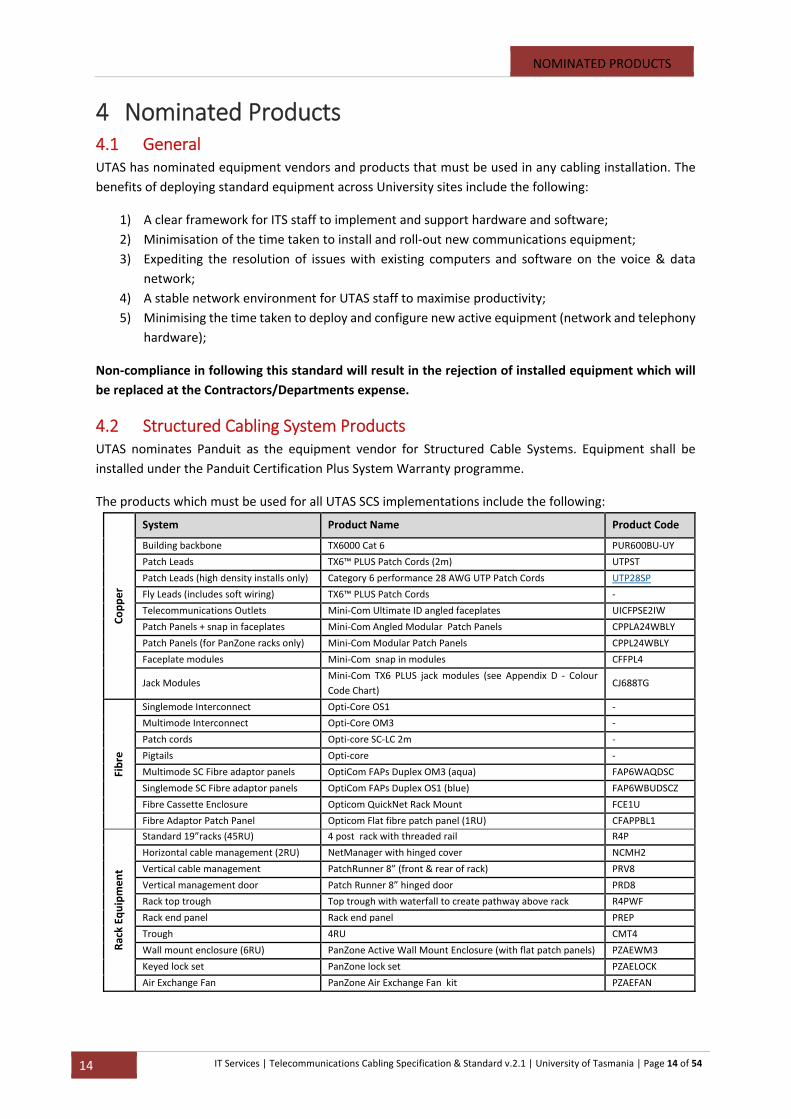
4.2 Structured Cabling System Products UTAS nominates Panduit as the equipment vendor for Structured Cable Systems. Equipment shall be
installed under the Panduit Certification Plus System Warranty programme.
The products which must be used for all UTAS SCS implementations include the following:
Copper
System Product Name Product Code
Building backbone TX6000 Cat 6 PUR600BU‐UY
Patch Leads TX6™ PLUS Patch Cords (2m) UTPST
Patch Leads (high density installs only) Category 6 performance 28 AWG UTP Patch Cords UTP28SP
Fly Leads (includes soft wiring) TX6™ PLUS Patch Cords ‐
Telecommunications Outlets Mini‐Com Ultimate ID angled faceplates UICFPSE2IW
Patch Panels + snap in faceplates Mini‐Com Angled Modular Patch Panels CPPLA24WBLY
Patch Panels (for PanZone racks only) Mini‐Com Modular Patch Panels CPPL24WBLY
Faceplate modules Mini‐Com snap in modules CFFPL4
Jack Modules Mini‐Com TX6 PLUS jack modules (see Appendix D ‐ Colour
Code Chart) CJ688TG
Fibre
Singlemode Interconnect Opti‐Core OS1 ‐
Multimode Interconnect Opti‐Core OM3 ‐
Patch cords Opti‐core SC‐LC 2m ‐
Pigtails Opti‐core ‐
Multimode SC Fibre adaptor panels OptiCom FAPs Duplex OM3 (aqua) FAP6WAQDSC
Singlemode SC Fibre adaptor panels OptiCom FAPs Duplex OS1 (blue) FAP6WBUDSCZ
Fibre Cassette Enclosure Opticom QuickNet Rack Mount FCE1U
Fibre Adaptor Patch Panel Opticom Flat fibre patch panel (1RU) CFAPPBL1
Rack Eq
uipment
Standard 19”racks (45RU) 4 post rack with threaded rail R4P
Horizontal cable management (2RU) NetManager with hinged cover NCMH2
Vertical cable management PatchRunner 8” (front & rear of rack) PRV8
Vertical management door Patch Runner 8” hinged door PRD8
Rack top trough Top trough with waterfall to create pathway above rack R4PWF
Rack end panel Rack end panel PREP
Trough 4RU CMT4
Wall mount enclosure (6RU) PanZone Active Wall Mount Enclosure (with flat patch panels) PZAEWM3
Keyed lock set PanZone lock set PZAELOCK
Air Exchange Fan PanZone Air Exchange Fan kit PZAEFAN
NOMINATED PRODUCTS
15 IT Services | Telecommunications Cabling Specification & Standard v.2.1 | University of Tasmania | Page 15 of 54
4.3 Panduit Warranty All UTAS SCS installations are to comply with the Panduit installation guidelines and shall obtain a Panduit
25 year Certification Plus System Warranty.
4.4 Other Vendor Equipment
4.4.1 Legacy Voice Service
Category 6 Balanced Copper Cable terminations: ACD‐Krone Series 2 Disconnect module, 10 pair.
Surge Protection devices for external cable terminations: ACD‐Krone Series 2 Arrestor magazine,
loaded, 500 volt.
4.5 Submission of Samples for Approval Samples of any proposed product variations by the Contractor to the product types specified in this
document shall be submitted to the UTAS ITS Project Manager for approval. Any alternative products must
comply with the requirements of the Panduit Certification Plus Warranty Program.

CONTRACTOR OBLIGATIONS
16 IT Services | Telecommunications Cabling Specification & Standard v.2.1 | University of Tasmania | Page 16 of 54
5 Contractor Certifications and Obligations 5.1 ACMA Registration The Telecommunications Cabler Provider Rules, 2000 (CPRs) require that all telecommunications cabling
be performed by registered cablers, and that all such cabling work shall comply with AS/ACMA S009:2013
(the Wiring Rules).
The contractor shall ensure that each of its cablers is registered with a current cabling licence through an
ACMA‐accredited Registrar and meets the competency, performance and skill requirements at the Open
level. All cablers undertaking Cabling Work on UTAS SCS must be registered at the Open level of
registration and certification.
5.2 Panduit Certification The contractor shall be accredited with Panduit as a current Panduit Certified Installer (PCI). The Contractor
shall ensure that all works meets the design, product selection, installation, testing and quality assurance
procedures such that the work will qualify for the Panduit 25‐year Performance Certification and the
Applications Assurance Program for copper and optical fibre structured cabling systems.
In addition to ensuring its ACMA licensing obligations for its cablers working on UTAS Structured Cabling
Systems, the Contractor shall ensure sufficient of its cablers have Panduit certifications as Panduit Certified
Installers.
5.3 Contractor’s Project Manager The Contractor shall appoint a qualified and suitably experienced Project Manager, and who has specific
experience in all aspects of telecommunications structured cabling, including product knowledge, design,
installation, testing and commissioning.
The contractor’s Project Manager shall liaise with the UTAS ITS Project Manager for each project and meet
the specified project management requirements of each job’s Project Plan.
5.4 Contractor’s Project Supervisor The Contractor shall appoint a Project Supervisor for on‐site, day‐to‐day supervision of the Contractor’s
cablers throughout the life of each project. The Project Supervisor shall have a current ACMA Open
registration.
The Contractor’s Supervisor shall also have Panduit certification as a Panduit Certified Installer and
extensive experience in the installation and testing of the Panduit products, tools and required measuring
equipment (such as nominated Fluke instruments) used in the project.
The Contractor’s Project Supervisor shall liaise with the UTAS CS&D Officer for each project on a regular
basis, and shall keep the Contractor’s Project Manager up to date with progress.
CONTRACTOR OBLIGATIONS
17 IT Services | Telecommunications Cabling Specification & Standard v.2.1 | University of Tasmania | Page 17 of 54
5.5 Contractor On‐Site Obligations
5.5.1 Contractor’s On‐Site Personnel
The Contractor shall submit to the ITS Project Manager the names, positions, qualifications and
certifications of its proposed Project Manager, Project Supervisor and cablers for approval by UTAS to
undertake the work. No work shall commence until approval of all personnel is obtained in writing from
UTAS. If the UTAS ITS Project Manager rejects any of the Contractor’s personnel the Contractor shall
propose a replacement who meets the skill, experience and certification requirements of UTAS and Panduit
for the work.
5.5.2 Project Management
The Contractor’s Project Manager shall manage all aspects of the cabling project against the agreed Project
Plan. The Project Plan and Contract documents will include this Specification and Statement of
Requirements.
The Contractor’s Project Manager shall maintain a close working relationship with the UTAS ITS Project
Manager for the cabling project, whether the Contract is directly between UTAS and the Contractor, or
whether the cabling work is a component of a major building project for which the Contractor is one of a
number of building sub‐contractors with a direct contractual relationship with the building Developer and,
thus, an indirect relationship with UTAS.
5.6 Panduit Installation Requirements The Contractor shall ensure that its designs and installation practices follow the current Panduit Design
and Installation Guidelines.
A Panduit Appendix H document shall be submitted to Panduit by the Contractor for approval prior to any
work commencing and within a timeframe which causes no delay in commencing the work. .
The Contractor shall submit a copy of Panduit certification status to the UTAS ITS Project Manager prior to
the commencement of the work indicating the names of the Contractor’s cablers with PCI certification and
including the appointed Contractor’s Project Supervisor.
5.7 Coordination with Other Works Where the cabling work is part of a major building project, or where the work will have an impact on
existing facilities, services amenities, or where the work is associated with concurrent other work, such as
electrical or mechanical installations, the Contractor and its Project Manager and UTAS Project Manager
shall ensure a coordination plan is developed which addresses site use and access, optimal concurrent work
schedules, safety, change management, liaisons, and reinstatement coordination.
5.8 Liaison with UTAS Commercial Services & Development UTAS facilities management of buildings, services and grounds within UTAS campuses are under the
responsibility of Commercial Services & Development (CS&D). In performing its cable work, the Contractor
shall adhere to both the CS&D standing conditions for undertaking works within UTAS and any specific
conditions applying to the particular UTAS facilities at the time of the project.
5.9 Liaison with External Authorities The Contractor shall meet all requirements of External Authorities, whether the Cabling Work is within
UTAS buildings, within UTAS campuses, or transiting public spaces or third party property.
CONTRACTOR OBLIGATIONS
18 IT Services | Telecommunications Cabling Specification & Standard v.2.1 | University of Tasmania | Page 18 of 54
In particular, all external underground cable pathways require Dial‐Before‐You‐Dig clearances to have been
gained, and all UTAS pathways require UTAS CS&D approval.
5.10 Work On Site The Contractor shall undertake all necessary investigations to fully inform itself of site conditions and other
factors that could impact on the execution of the works. As well as general investigations in and around
the site, the investigations shall include, but not be limited to, structural hazards, asbestos materials,
Heritage status, and environmental impacts.
5.11 Site Inspection It is the Contractor’s responsibility to arrange for and to undertake a site inspection for work quoting,
planning, scoping and determining coordination requirements with concurrent works or potential project
impacts.
No claims will be accepted for ignorance of the then current conditions or measurement and dimension
errors.
5.12 External Civil Works In general, all excavations for external UTAS Structured Cabling System work shall be the responsibility of
the Contractor unless explicitly specified to the contrary. The Contractor shall be responsible for all
excavation, cable protection, back fill, surface restoration and the installation of cable markers. All
excavation and back fill works shall be carried out with the use of hand tools, except where the use of
mechanical or power‐assisted tools is permitted when specifically stated in the particular project’s contract
documents or if authorised in writing by the UTAS CS&D.
Before proceeding with any excavation work, the Contractor shall ascertain details of any underground
services in the area. Where excavations are required near footings, foundations, concrete floors, etc. the
Contractor shall ensure that the earthworks do not interfere with these structures and backfill is well
consolidated.
Unless otherwise agreed by the UTAS CS&D, the Contractor shall arrange the installation so that all
trenches are excavated and back‐filled on the same day.
The Contractor shall ensure that the specified safety precautions are observed at all excavations by the
provision of safety barriers, warning notices, shoring, work authority requirements are obtained and any
other items as deemed necessary are obtained and provided.
5.13 Reinstatement of Penetrations Where the Contractor had made or has been provided with building, wall, floor or other structural
penetration for the egress of a UTAS Structured Cabling System pathway, the Contractor shall seal all
residual openings. The Contractor shall ensure that all pathway penetrations are sealed to the fire rating
of the structure and use approved fire retardant materials. All seals of pathway penetrations shall prevent
the ingress of unauthorised personnel, moisture, rain, seepage, UV radiation, dust, rodents and insects.
5.14 Work in UTAS Non‐Standard and Designated “Restricted” Areas UTAS has a number of non‐standard and designated “Restricted” work areas in which network access is
required. Such areas include, but are not limited to, medical “Wet” areas, bio‐hazard areas, chemical
hazard areas, mechanical and hydraulic hazard areas, clean rooms, sensitive electronic equipment labs,
CONTRACTOR OBLIGATIONS
19 IT Services | Telecommunications Cabling Specification & Standard v.2.1 | University of Tasmania | Page 19 of 54
radio telescopes, nuclear radiation areas. Each area is separately managed by a local facilities manager or
area custodian. The Contractor shall ensure that all local as well as general UTAS access requirements are
met for work within such areas. The Contractor shall specifically obtain access approval from the respective
local facilities manager or area custodian and comply with the respective access and outage schedule.
5.15 Minor Materials, Fittings and Consumables The Contractor shall provide all minor materials, fittings, corrosion protection, painting treatments and
consumables required for the Cabling Works and for any site restoration works, in accordance with
accepted trade practices, requirements of the Wiring Rules and manufacturers’ recommendations.
All fittings shall be uniform for a particular project and shall comply with the product manufacturer’s fitting
specifications for the Structured Cabling System (SCS) components.
These items shall not be charged for separately.

CABLING SYSTEM SPECIFICATIONS
20 IT Services | Telecommunications Cabling Specification & Standard v.2.1 | University of Tasmania | Page 20 of 54
6 UTAS Structured Cabling System Specifications 6.1 Structured Cabling Systems (SCS) The UTAS SCS shall comply with Clause 5 of AS/NZS 3080:2003.
The UTAS SCS applies to a set of integrated physical cabling systems, one for each campus and location.
Each SCS includes the cables, cable pathways, any dedicated telecommunications rooms or spaces, cable
terminating and patching enclosures, cable interconnect and cross‐connect distribution devices and
hardware, cable management systems, surge suppression devices, patch cords and work area cords.
Cables are internal and external and optical fibre and balanced copper. Cable pathways are external and
internal and include all the hardware elements required to maintain a contiguous path, but exclude the
path route. External pathways are aerial and underground. Internal pathways are within buildings, inter
and intra‐floor.
Functional elements of a Structured Cabling System (Figure 3, pg. 20) include a Campus Distributor, campus
cables, which form the physical infrastructure for the campus area network and interconnect the Campus
Distributor to each building at a Building Distributor. Within each building, building cabling, generally
within vertical cable pathways, interconnects each floor, from a Floor Distributor, back to the Building
Distributor, which is located in a dedicated telecommunications space. Each floor has one or more Floor
Distributors. Horizontal cabling interconnects Telecommunications Outlets (TOs) to a Floor Distributor.
The Campus Distributor is the interconnection boundary with external telecommunications carrier services
or Wide Area Network (WAN) links. The TO provides the interface with terminal equipment (network
connecting devices), generally within work areas. Cabling between a TO and a network connecting device
is part of the SCS and generally referred to as work area cabling, cords, or patch leads.
The UTAS SCS is hierarchical from Campus Distributor to TOs. The Campus, Building and Floor Distributors
provide both cabling cross connect or interconnect capability, and active networking and
telecommunications equipment cross connect or interconnect capability. Some smaller and single storey
buildings combine the Building and Floor Distributor functions. Some UTAS sites are single building
locations for which the Campus Distributor and Building Distributor functions are combined.
For the UTAS SCS in general, Campus cabling is single mode optical fibre, Building cabling is multimode
optical fibre, and horizontal cabling is balanced copper. Legacy cabling includes balanced copper external
cable plant for voice‐based campus cabling and multimode optical fibre for older campus area network
cabling.
FIGURE 3: GENERIC STRUCTURED CABLING SYSTEM – ELEMENTS
CABLING SYSTEM SPECIFICATIONS
21 IT Services | Telecommunications Cabling Specification & Standard v.2.1 | University of Tasmania | Page 21 of 54
Within the UTAS SCS, a channel is the contiguous, end‐to‐end link between active telecommunications
equipment, including, in general, router to switch, distribution switch to edge switch, switch to terminal
equipment (network connecting device), switch to wireless access point, gateway (IP‐to‐analogue) to
telephony end point. (See Figure 1, pg. 12 and Figure 2, pg. 13).
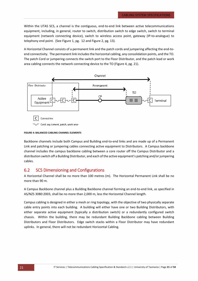
A Horizontal Channel consists of a permanent link and the patch cords and jumpering affecting the end‐to‐
end connectivity. The permanent link includes the horizontal cabling, any consolidation points, and the TO.
The patch Cord or jumpering connects the switch port to the Floor Distributor, and the patch lead or work
area cabling connects the network connecting device to the TO (Figure 4, pg. 21).
Backbone channels include both Campus and Building end‐to‐end links and are made up of a Permanent
Link and patching or jumpering cables connecting active equipment to Distributors. A Campus backbone
channel includes the campus backbone cabling between a core router off the Campus Distributor and a
distribution switch off a Building Distributor, and each of the active equipment’s patching and/or jumpering
cables.
6.2 SCS Dimensioning and Configurations A Horizontal Channel shall be no more than 100 metres (m). The Horizontal Permanent Link shall be no
more than 90 m.
A Campus Backbone channel plus a Building Backbone channel forming an end‐to‐end link, as specified in
AS/NZS 3080:2003, shall be no more than 2,000 m, less the Horizontal Channel length.
Campus cabling is designed in either a mesh or ring topology, with the objective of two physically separate
cable entry points into each building. A building will either have one or two Building Distributors, with
either separate active equipment (typically a distribution switch) or a redundantly configured switch
chassis. Within the building, there may be redundant Building Backbone cabling between Building
Distributors and Floor Distributors. Edge switch stacks within a Floor Distributor may have redundant
uplinks. In general, there will not be redundant Horizontal Cabling.
FIGURE 4: BALANCED CABLING CHANNEL ELEMENTS

CABLING SYSTEM SPECIFICATIONS
22 IT Services | Telecommunications Cabling Specification & Standard v.2.1 | University of Tasmania | Page 22 of 54
7 Cabling Specifications for New Works 7.1 Cables – General All cables shall meet the requirements of Clause 5.6 of AS/CA S008:2010, which details requirements for
the design, identification, materials, mechanical and electrical parameters for balanced copper and optical
fibre cables to be used in the UTAS SCS.
7.2 Horizontal Cabling for Permanent Link UTAS Horizontal cabling shall be balanced copper and shall support two options, either Category 6 or
Category 6A (where speeds of 10G are required).
7.3 Horizontal Cabling for Cords Horizontal cabling cords for equipment termination, jumpering and work area termination shall be Cat 6
or Cat 6A balanced cables. Standardised cord lengths for patching and jumpering shall be 2m. Work area
cords shall be available with lengths of 1 m, 2 m, 3 m, 4 m and 5 m, and selected such that the Horizontal
Channel length is within 100 m.
Different cord colours shall be used to differentiate UTAS telecommunications services, according to the
UTAS Patch Lead Colour Code (See Appendix D ‐ Colour Code Chart).
7.4 Building Backbone Cables UTAS Building Backbone Cable channels shall be at minimum multimode optical fibre, and for the Legacy
Voice Service, balanced copper cabling.
Multimode optical fibre shall be OM3.
For balanced copper cabling for analogue telephone services, typically 100 pair cables shall be run between
the Building Distributor and each Floor Distributor.
7.5 Campus Backbone Cables Campus Backbone Cable channels shall be single mode optical fibre cabling and Balanced Copper Cable for
Legacy Voice Services. Campus cable pathways shall, in general, be underground conduit only.
Campus backbone optical fibre cables shall have at least 24 to 48 fibre cores per cable. Campus backbone
balanced copper cables shall have at least 100 pairs per cable.
Cable sizing and any requirement for aerial cabling will be specified by ITS for each cable project.
Underground cables shall be jelly filled, loose tube, UV stabilised polyethylene sheathed, UV stabilised
nylon jacket and comply with the specifications for outdoor optical fibre cables at Clause 5.6 of AS/CA
S008:2010 with respect to construction and cladding, and for physical, mechanical and environmental
ratings.
Single mode optical fibre shall be OS1, capable of supporting up to 10 Gigabits per second Ethernet. The
optical fibre shall be suitable to both 1310 nm and 1550 nm wavelengths. The Campus backbone channel
is specified for up to 2,000 m.
7.5.1 Legacy Voice Service Balanced Copper Cables
CABLING SYSTEM SPECIFICATIONS
23 IT Services | Telecommunications Cabling Specification & Standard v.2.1 | University of Tasmania | Page 23 of 54
New Campus Backbone and Building Backbone Balanced Copper Cables shall only be installed to support
legacy UTAS PABX systems between the PABX Campus Distributor and each Building Distributor, and
between the Building Distributor and each Floor Distributor to support any legacy analogue telephone
handsets and the ongoing requirement for emergency analogue end points, such as emergency help points
and lift phones.
Balanced Copper Cables on the campus backbone shall be outdoor, screened, 0.64mm diameter plain
annealed copper conductors, cellular polyethylene insulated, twinned, bunched into 10 pairs units, jelly
filled interstices, taped, moisture barrier, UV stabilised polyethylene overall sheathed and UV stabilised
nylon jacketed Category 3 cables meeting the specified requirements of AS/ACIF S008:2003. Cable sizing
will be up to 100 pairs, depending on the specific application.
7.6 Terminations specifications for new Cabling Work
7.6.1 General
All cables shall meet the requirements of Clause 5.7 of AS/CA S008:2010, which details requirements for
the design, identification, materials, mechanical and electrical parameters for plugs, sockets and
connecting hardware to be used in the UTAS SCS.
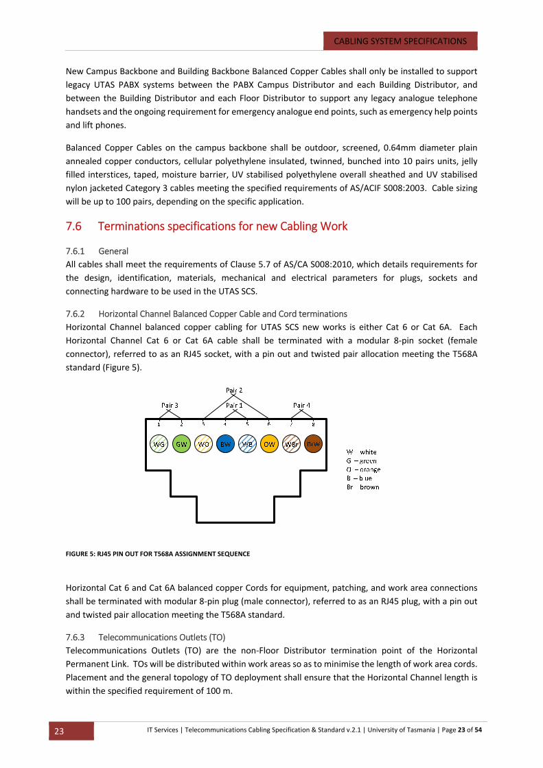
7.6.2 Horizontal Channel Balanced Copper Cable and Cord terminations
Horizontal Channel balanced copper cabling for UTAS SCS new works is either Cat 6 or Cat 6A. Each
Horizontal Channel Cat 6 or Cat 6A cable shall be terminated with a modular 8‐pin socket (female
connector), referred to as an RJ45 socket, with a pin out and twisted pair allocation meeting the T568A
standard (Figure 5).
Horizontal Cat 6 and Cat 6A balanced copper Cords for equipment, patching, and work area connections
shall be terminated with modular 8‐pin plug (male connector), referred to as an RJ45 plug, with a pin out
and twisted pair allocation meeting the T568A standard.
7.6.3 Telecommunications Outlets (TO)
Telecommunications Outlets (TO) are the non‐Floor Distributor termination point of the Horizontal
Permanent Link. TOs will be distributed within work areas so as to minimise the length of work area cords.
Placement and the general topology of TO deployment shall ensure that the Horizontal Channel length is
within the specified requirement of 100 m.
FIGURE 5: RJ45 PIN OUT FOR T568A ASSIGNMENT SEQUENCE

CABLING SYSTEM SPECIFICATIONS
24 IT Services | Telecommunications Cabling Specification & Standard v.2.1 | University of Tasmania | Page 24 of 54
TOs shall be for Cat 6 and Cat 6A Balanced Copper Cable terminations, using modular 8‐pin RJ45 sockets
with T568A pin assignments. Different outlet colours shall be used to differentiate UTAS
telecommunications services, according to the UTAS Patch Panel Colour Code Chart (see Appendix D ‐
Colour Code Chart).
TO options include; angled wall plates with triple or quad outlets per staff workstation. In areas such as
student labs, single TOs may be sufficient. All products shall be approved by ITS and listed in the nominated
SCS products (see Clause 4.2, pg. 14).
Each TO socket shall have a permanent label meeting the UTAS TO Labelling Standard and be visible to
UTAS users, network support and maintenance staff.
7.6.4 Distributor Balanced Copper terminations
All Balanced Copper Cables shall terminate within a Distributor on to a 19‐inch rack mounted Patch Panel.
Distributor Patch Panels for balanced cabling and active equipment interconnections and/or cross
connections shall be made up of 24‐way 19‐inch rack mounted modular units populated with modular 8‐
pin RJ45 sockets with T568A pin assignments. RJ45 socket density shall be 24 sockets per 1 RU.
7.6.5 Legacy Voice Service Cable terminations
Legacy Voice Service balanced copper Building Backbone and Campus Backbone Cable shall be terminated
on to 10 pair Krone Disconnect modules on separate Krone racks within the Campus Distributor and each
Building Distributor. Balanced copper Building Backbone Cables shall terminate on to 24 port RJ45 Patch
Panels within Floor Distributors and be cross connected to Cat 6 Horizontal cabling. Each pair of a multi‐
pair Building Backbone Cable shall be terminated.
7.6.6 Optical Fibre Cable terminations
In general, optical fibre cores on Building Backbone and Campus Backbone optical fibre cables shall be
terminated with fusion splicing to Pigtail assemblies of SC connectors.
The optical fibre cables shall terminate on to an optical fibre Patch Panel within the respective Distributor
space. A consistent connection scheme shall be maintained through physical keying or latching, colour
coding and labelling to ensure consistent end‐to‐end polarity, such that the A side of one connector pair
matches the B side of the other connector pair for any Permanent Link and patch Cord.
Optical fibre patch Cords shall be terminated in SC plug connectors. Multimode patch Cords shall be duplex
SC to SC and OM3 rated. Single mode patch Cords shall be duplex SC to SC and OM1 rated.
7.6.7 Wireless Access Point terminations
UTAS deploys IEEE 802.11n wireless access points (WAPs) across all campuses, predominately within
buildings, and predominately within the ceiling spaces of each floor (or at ceiling height where there is
insufficient ceiling void space). Each WAP location shall have dual horizontal cables terminated to support
the in‐line power requirements of the WAP.
New building project drawings will identify non‐specific in‐ceiling locations for TOs. The optimal location
of a WAP will not be determined until after a building has been occupied and when fixtures, fittings,
equipment and people are accommodated. Consequently, the Horizontal Channel length for each WAP
shall be such that the TO can be located anywhere within the ceiling space of the nominated coverage area
and meet the 90 m requirement.
CABLING SYSTEM SPECIFICATIONS
25 IT Services | Telecommunications Cabling Specification & Standard v.2.1 | University of Tasmania | Page 25 of 54
7.7 Distributors, Patch Panels and Cable Management
7.7.1 General
Distributors are cable channel sub‐system end points to provide for the mechanical and physical
interconnection and cross connection of cabling sub‐systems, active equipment and external
interconnections. A Distributor will house active equipment, cable termination hardware and Patch Panels,
and including rack‐based cable management systems. Distributors shall be located to ensure cable channel
lengths are within the channel performance specifications in for balance copper cabling (see Clause 6,
AS/NZS 3080:2003) and for optical fibre cabling (see Clause 8, AS/NZS 3080:2003).
7.7.2 Balanced Copper Cable Patch Panels
Patch Panels for Cat 6 cabling shall be 19‐inch rack mounted frames as specified in this document, (refer
Clause 5.2, pg. 20).
Patch Panels shall be 24‐way modular RJ 45 sockets with a density of 24 sockets per 1 RU. Patch Panels
shall be fully populated with sockets.
7.7.3 Optical Fibre Cable Patch Panels
Patch Panels optical fibre cabling shall be 19‐inch rack mounted frames as specified in clause 5 of this
document.
Optical fibre termination equipment shall provide interconnect, cross connect and splicing capabilities.
Patch Panels shall be 1RU for 12 or 24 connections. Colour coding of connectors and adaptors shall be
used to ensure incorrect matings do not occur. In addition physical keying or latching shall be used to
ensure consistent polarity of duplex connectors is maintained.
Connectors and adaptors shall be colour coded to differentiate single mode from multimode optical fibres,
and for distinguishing any legacy multimode OM1 fibres from OM3 fibres.
Mechanical and optical characteristics of all optical fibre connecting hardware shall meet the requirements
of Clause 5 of AS/NZS 3080:2003.
7.7.4 Cable Management Systems
Rack‐based cable management systems shall be 19‐inch rack modules capable of containing and physically
managing Cat 6 and optical fibre cables and Cords, (refer Clause 5.2, pg. 20 and Appendix D).
7.8 Overvoltage Protection All outdoor Balanced Copper Cables shall have overvoltage surge protection on all pairs at the cable
termination frame in accordance with AS 4262.1‐1995 and AS 4262.2‐1999.
7.9 Earthing Cable Screens Earthing and bonding of cable screens shall be in accordance with AS/NZS 3000:2007 and IEC 60364‐1. Any
cable screens shall be bonded at each distributor on to the cable termination rack which, in turn, shall be
bonded to the building earth.
Bonds shall ensure a permanent, continuous, low impedance electrical path to earth, with each equipment
rack individually bonded. The cable screen shall provide a path to earth for any elements which connect
to the screen.

CABLING SYSTEM SPECIFICATIONS
26 IT Services | Telecommunications Cabling Specification & Standard v.2.1 | University of Tasmania | Page 26 of 54
Earthing and bonding bars shall be insulated from any conductive sources to withstand a potential
difference of 1.5 kV AC (50 Hz) for 60 seconds.

PATHWAYS SPECIFICATIONS
27 IT Services | Telecommunications Cabling Specification & Standard v.2.1 | University of Tasmania | Page 27 of 54
8 UTAS SCS Pathways Specifications 8.1 Pathway, Enclosure and Space Design Appendix ZB of AS/NZS 3084:2003 provides detailed design information supporting the generic
specifications and requirements for pathway, enclosures and telecommunications spaces within AS/NZS
3084:2003. This design information shall for the basis of the requirements of this Section.
Where cabling is installed through public spaces the end result should be neat, tidy and non‐intrusive using
appropriate material/products for the setting.
8.2 Pathway Routing and Separation from Power Services Cable pathways shall be selected, designed and routed to maintain minimum mandatory segregation from
power cables and lightning down conductors in accordance with Appendix ZA, Clause ZA.3.1 of AS/NZS
3080:2003 and Clause 9 of AS/CA S008:2010; and to minimise coupling interference between
telecommunications cables and power cables in accordance with Appendix ZA, Clause ZA.3.2 of AS/NZS
3080:2003.
8.3 Intra‐building Pathways Intra‐building pathways include pathways for Building Backbone Cabling sub‐systems and Horizontal
Cabling sub‐systems.
Specific and detailed design information for Building Backbone pathways is in Appendix ZB4 of AS/NZS
3084:2003.
Building pathways shall be designed to handle all telecommunications media and sized to accommodate
future building capacity and future floor capacity for the different cable types, including life cycle
replacements and removal and bending radius requirements.
Outside of special purpose telecommunications and data centre spaces, ducts and trays should be located
above the ceiling. Installation of pathways in both air plenums and non‐plenum hollow‐ceiling systems
shall meet the requirements of AS/NZS 3000:2007 and environmental and fire rating requirements of
Australian building codes and regulations.
Where there is more than one floor, risers should be located vertically one above the other and shall be
vertically interconnected by conduits or tray.
All cables shall be concealed except where nominated otherwise, and shall be run in neat lines. Surface
mounted ducting shall be installed where an alternative method for concealment in not possible.
Pathways for open office furniture areas shall be fed from the specified adjacent Horizontal pathway,
whether from ceiling, floor or building walls or service columns. Separate power and telecommunications
channels and compartments are required and shall meet the specified separation requirements.
Where the new building design or the building modification specify Horizontal Channel pathways inside
dry wall cavities for wall plate TOs, cable runs shall meet power cable separation requirements for vertical
runs.
PATHWAYS SPECIFICATIONS
28 IT Services | Telecommunications Cabling Specification & Standard v.2.1 | University of Tasmania | Page 28 of 54
8.4 Campus Pathways Campus pathways shall be constructed to accommodate the cabling between buildings and Campus
Backbone Cable loop topologies. Campus pathways shall be designed to handle all telecommunications
cable media. A campus entrance pathway shall be provided for cable access for Carrier services and UTAS
WAN services.
Campus pathways shall be underground conduit, unless:
The campus layout facilitates a suitably designed above ground pathway, such as covered
walkways and gantries or building links;
There is a specific limitation either preventing the undergrounding of the pathway for which an
aerial solution is the only possibility; or
Where direct burial is required for a portion of the pathway, for example under road.
UTAS easements and rights‐of‐way for campus facilities cabling and services shall be used where
designated. Common services trenches will, generally, be available for access to new buildings.
All new buildings and capital works shall have at least one and preferably two defined means of ingress for
campus cables.
TELECOMMUNICATIONS SPACES
29 IT Services | Telecommunications Cabling Specification & Standard v.2.1 | University of Tasmania | Page 29 of 54
9 Telecommunications Spaces 9.1 General UTAS Telecommunications Spaces shall be designed in accordance with Clause 6 and Appendix ZB2 of
AS3084:2003.
Telecommunications Spaces should not be shared with electrical installations other than those for
telecommunications. Equipment not related to the support of the telecommunications room shall not be
installed in the telecommunications room.
UTAS has three Classes of dedicated telecommunications spaces. Class 1 telecommunications room
supports the Campus Distributor for each campus. In the case of the Sandy Bay Campus, the space is shared
with the UTAS main Data Centre. Class 2 Node Rooms support Building Distributors and Class 3
telecommunications spaces support Floor Distributors.
In general, each separate UTAS Building shall contain a Class 2 Building Distributor as a minimum
requirement.
Under circumstances where it is not possible to install a dedicated Telecommunications Space there may
be a requirement to install a stand‐alone distribution solution. All designs for non‐standard distribution
points must be designed in co‐ordination with and approved by the UTAS Infrastructure Manager.
9.1.1 Campus Distributers
New dedicated telecommunications equipment room designs for Class 1 Telecommunications Rooms
(Comms Rooms) for Campus Distributors shall meet the requirements specified in Clause 6 and Appendix
ZB2 of AS3084:2003.
Telecommunications Rooms shall be located as close as practicable to the centre of the area served and
preferable in the core area.
9.1.2 Building Distributers
New dedicated telecommunications equipment room designs for Class 2 Comms Rooms for Building
Distributors shall meet the requirements specified in Clause 6 and Appendix ZB2 of AS3084:2003.
Comms Rooms shall be located as close as practicable to the centre of the area served and preferable in
the core area.
9.1.3 Floor Distributers
Rooms for Floor Distributors shall be located to meet the Horizontal Channel maximum length requirement
for Category 6 and 6A balanced copper cabling of 90 m, and strategically located to minimise the number
of spaces required in large floor environments.
Where there is more than one floor, Communications Rooms should be located vertically one above the
other.
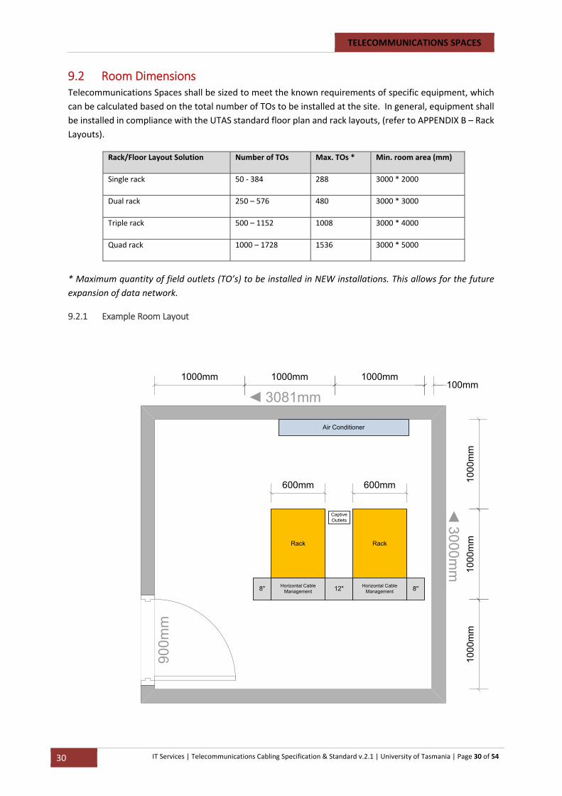
TELECOMMUNICATIONS SPACES
30 IT Services | Telecommunications Cabling Specification & Standard v.2.1 | University of Tasmania | Page 30 of 54
9.2 Room Dimensions Telecommunications Spaces shall be sized to meet the known requirements of specific equipment, which
can be calculated based on the total number of TOs to be installed at the site. In general, equipment shall
be installed in compliance with the UTAS standard floor plan and rack layouts, (refer to APPENDIX B – Rack
Layouts).
Rack/Floor Layout Solution Number of TOs Max. TOs * Min. room area (mm)
Single rack 50 ‐ 384 288 3000 * 2000
Dual rack 250 – 576 480 3000 * 3000
Triple rack 500 – 1152 1008 3000 * 4000
Quad rack 1000 – 1728 1536 3000 * 5000
* Maximum quantity of field outlets (TO’s) to be installed in NEW installations. This allows for the future
expansion of data network.
9.2.1 Example Room Layout
3081mm
3000mm
Rack
8"12" Horizontal Cable Management
600mm
1000
mm
1000
mm
100
0m
m
1000mm1000mm100mm
Captive Outlets
Horizontal Cable Management8"
Rack
1000mm
600mm
Air Conditioner
900m
m
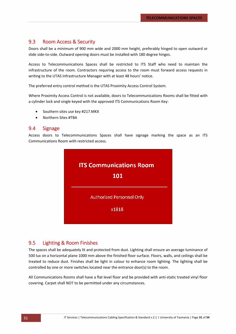
TELECOMMUNICATIONS SPACES
31 IT Services | Telecommunications Cabling Specification & Standard v.2.1 | University of Tasmania | Page 31 of 54
9.3 Room Access & Security Doors shall be a minimum of 900 mm wide and 2000 mm height, preferably hinged to open outward or
slide side‐to‐side. Outward opening doors must be installed with 180 degree hinges.
Access to Telecommunications Spaces shall be restricted to ITS Staff who need to maintain the
infrastructure of the room. Contractors requiring access to the room must forward access requests in
writing to the UTAS Infrastructure Manager with at least 48 hours’ notice.
The preferred entry control method is the UTAS Proximity Access Control System.
Where Proximity Access Control is not available, doors to Telecommunications Rooms shall be fitted with
a cylinder lock and single keyed with the approved ITS Communications Room Key:
Southern sites use key #217.MKX
Northern Sites #TBA
9.4 Signage Access doors to Telecommunications Spaces shall have signage marking the space as an ITS
Communications Room with restricted access.
9.5 Lighting & Room Finishes The spaces shall be adequately lit and protected from dust. Lighting shall ensure an average luminance of
500 lux on a horizontal plane 1000 mm above the finished floor surface. Floors, walls, and ceilings shall be
treated to reduce dust. Finishes shall be light in colour to enhance room lighting. The lighting shall be
controlled by one or more switches located near the entrance door(s) to the room.
All Communications Rooms shall have a flat level floor and be provided with anti‐static treated vinyl floor
covering. Carpet shall NOT to be permitted under any circumstances.

TELECOMMUNICATIONS SPACES
32 IT Services | Telecommunications Cabling Specification & Standard v.2.1 | University of Tasmania | Page 32 of 54
9.6 Power Two separate power supply circuits shall be provided to serve the Telecommunications Space with
dedicated industrial style captive plugs and sockets (minimum 15A power ‐ to be specified by ITS depending
on equipment load).
If an emergency power source (generator) is available in the building, the Telecommunications Space shall
be linked to the emergency supply.
In addition, a minimum of two “convenience” GPOs and data outlets shall be provided for general use
equipment and their locations shall be coordinated with the UTAS Infrastructure Manager.
9.7 Room Cooling & Ventilation Telecommunications Spaces shall be maintained at a temperature below 30 degrees Celsius. If the
temperature requirements can be maintained by the incorporation of adequate ventilation means, then
mechanical cooling is not required. If this temperature range cannot be maintained by ventilation alone,
then mechanical cooling will be required. A 20% growth factor for cooling/ventilation is to be included in
the design.
Do NOT location Communications rooms where additional head loads are likely to occur i.e. North/West
facing façade or in a room with a window.
9.8 Design of Telecommunications Rooms
9.9 Enclosures and Racks
9.9.1 General
Enclosures and racks shall comply with the relevant requirements of IEC‐60297 and Clause 5.4 of AS/CA
S008:2010.
All four (4) post racks will be secured to the floor secured to the floor. All rack installations shall be
grounded.
Enclosures and open frame racks shall be bonded to the protective earth system or communications earth
system using a minimum 2.5mm2 green/yellow conductor. Enclosures and open frame racks shall not be
bonded to the Telecommunications Reference Conductor if provided.
Power distribution will be provided as an integral part of the rack/cabinet in the form of a 1RU Transfer
Switch and mounted in the centre‐back of the rack. Each Transfer Switch is to be connected directly into
the UPS and also a separate power circuit with an industrial type captive plug and socket.
9.9.2 Standard Cabinets and Racks
The standard racks for UTAS telecommunications equipment and SCS terminations, interconnects and
cross connects is Panduit. All Racks shall be installed and configured to comply with UTAS standard rack
layouts and parts list, (see Clause 4.2, pg.14).
9.9.3 Cable management
Racks shall be supplied with cable management panels to facilitate the support and organising of patch
cords between Patch Panels and switching equipment. Each rack shall be installed with a horizontal trough
across the top and bottom of each rack, two instances of 2RU horizontal management and vertical
management on each side of each rack.

TELECOMMUNICATIONS SPACES
33 IT Services | Telecommunications Cabling Specification & Standard v.2.1 | University of Tasmania | Page 33 of 54
Installations with more than 2 adjacent enclosures/racks to have cable ladder across the rack tops. Patch
cables shall be routed as per UTAS specifications, (see APPENDIX C – Cable Routing).
INSTALLATION REQUIREMENTS
34 IT Services | Telecommunications Cabling Specification & Standard v.2.1 | University of Tasmania | Page 34 of 54
10 UTAS SCS – Installation Requirements 10.1 General Installation Requirements Cabling Work must be undertaken by qualified and registered cablers who shall comply with the Wiring
Rules (AS/CA S008:2010) as a minimum installation requirement.
Cablers shall comply with Commonwealth and Tasmanian Occupational Health and Safety legislation and
requirements, including Building Code requirements.
General requirements for all installation work on the UTAS SCS shall include:
Safe and sound practices, including hazard identification and management;
Compliance with Standards and Regulations;
Installation in a professional manner which meets the requirements of the Building Code of
Australia and the aesthetic requirements of UTAS;
Installation in accordance with Wiring Rules instructions;
Installation in accordance with manufacturer installation instructions;
Equipment labelled in accordance with the Telecommunications Labelling Notice;
Cable terminations interconnections and cross connections labelled in accordance with UTAS
labelling policy;
Installation which protects against mechanical and environmental damage or exposure;
Installation of products and equipment which is fit for purpose for intended use;
Installation of cables with due care to prevent exceeding maximum hauling tensions, bending radii
and crush ratings.
10.2 Installation of Cabling
10.2.1 General
Cables shall be installed according to the mandated requirements of AS/ACIF S2009:2006 – the
Communications Wiring Rules.
Cables shall not be installed under residual tension or pressure except as required to secure to cable
pathways.
All cable runs shall be continuous along the Permanent Link between the termination points specified.
All cables shall meet the manufacturers’ minimum bending radii.
All mechanical protection and cable supports shall be free of burrs and sharp edges and all steps shall be
taken to protect the cables from installation damage and in‐situ damage throughout the life of the cable.
Separation distances from power cables as specified in the Communications Wiring Rules and in the AS/NZS
3000:2007 Wiring Rules shall be rigorously adhered to.
10.2.2 Indoor Cabling
UTAS SCS installations shall comply with the indoor cabling requirements as set out in Clause 16 of AS/CA
S008:2010.
INSTALLATION REQUIREMENTS
35 IT Services | Telecommunications Cabling Specification & Standard v.2.1 | University of Tasmania | Page 35 of 54
Cables shall not be installed under residual tension or pressure except as required to secure to cable tray
or catenary cable. All cable runs shall be continuous along its Permanent Link, between the termination
points specified, with no joints, splices, junctions, or similar permitted.
10.2.3 Allowance for Spare Cable Length – Balanced Copper
All Balanced Copper Cables into a Floor Distributor shall include a provision for 3 m of spare cable to allow
for any future rack or cabinet relocation of any rack.
Slack retention at termination points shall be restricted to the amount of cable required for re‐termination
(less than 1 m). The storage of cable shall comply with the minimum bend radius for that cable type as per
manufactures specifications.
Slack cable shall only be allowed in skirting duct if minimum bend radius can be achieved.
10.2.4 Allowance for Spare Cable Length – Optical Fibre
All optical fibre cables into any Distributor shall include a provision for 3 m of spare cable to allow for any
future rack or cabinet relocation of any rack.
To provide an allowance for fibre cable re‐termination at some future time, provision is to be made for
additional 2 m of unsheathed fibre to be looped at each end of each cable run. This spare length shall be
housed within the Fibre Optic Enclosure. Cable looping shall not exceed the manufacturer’s minimum
bending radius requirements.
Where the fibre is run through external conduit and pit systems, there shall be an allowance of two times
the circumference of the pit left in the first and last pit locations. Where this cannot be achieved, a
minimum of a 2 m fibre loop within the first and last pit shall apply.
10.2.5 Termination of Legacy Voice Service Cabling at Floor Distributor
Cat 6 cables used for Legacy Voice Service Building Backbone cabling between the Building Distributor and
the Floor Distributor shall be terminated on to 24 port RJ45 Patch Panels within the Floor Distributor.
Cat 6 cable sizing will be in multiples of 25 pairs, typically ranging from 1 to 4 multiples (ie, 25 pair to 100
pair cables). All cable pairs shall be terminated on to the Floor Distributor Patch Panels. The following
termination arrangements shall apply:
10.3 Installation of Cable Pathways & Cable Support Systems
10.3.1 General
The Contractor shall provide all mechanical protection for cable pathways and the cables supported within
the pathways.
Panduit cable pathways shall be used and installed in conformance with the manufacturer’s specification,
guidelines and recommendations.
All pathways shall be sized to accommodate 140% of the maximum capacity of the Distributor being served.
The following UTAS standard pathways shall be used unless otherwise directed by the UTAS ITS Project
Officer or nominated in a particular project’s specifications:
Outdoor cables in underground conduits
Overhead cable trays within dedicated telecommunications spaces
INSTALLATION REQUIREMENTS
36 IT Services | Telecommunications Cabling Specification & Standard v.2.1 | University of Tasmania | Page 36 of 54
Horizontal pathways
10.3.2 Installation of Intra‐building Cable Pathways
Installation of UTAS intra‐building cable pathways shall meet the installation requirement of Appendix ZB3
of AS/NZS 3084:2003 for each pathway type installed.
10.3.3 Installation of Campus Cable Pathways
Installation of UTAS intra‐building cable pathways shall meet the installation requirement of Appendices
ZB4 and ZB5 of AS/NZS 3084:2003 for each pathway type installed.
10.3.4 Cable Entry and Building Penetrations
UTAS cable entries and building penetrations shall meet the installation requirements Appendices ZB3, ZB4
and ZB5 of AS/NZS 3084:2003 and the UTAS Facilities Management guidelines for building penetrations.
10.3.5 Telecommunications Pits
When required, pits shall be installed every 30 m or at every change in direction. The Contractor shall install
a pit having adequate dimensions to contain loops of cabling while maintaining the manufacturers’
minimum bend radius requirements.
Pits shall be minimum 800 mm deep.
Each pit shall be provided with a seepage hole cast into the bottom surface to allow the disbursement of
any accumulated water. Pits shall be provided with appropriate strength lids depending on the placement
of the pits. Pit lids should be capable of being locked to prevent unauthorised entry. Lids shall be sealed
to prevent rodent occupation.
Draw cords shall be installed in all electrical conduits and be continuous and without joins for the full
length of the conduit. A 2 m length "tail" shall be provided at each end of the draw cord. Tails shall be
coiled and neatly laid in the relevant area. Draw cords shall be 4 mm diameter polyethylene mono rope
with a breaking load of 5 kN. A draw chord shall remain in a conduit following installation of cables.
All pit installation shall comply in full to the manufactures installation guidelines.
10.3.6 Installation of Enclosures
UTAS SCS installations shall comply with the enclosure requirements as set out in Clause 8 of AS/CA
S008:2013 and Appendix D of AS/CA S008:2013 for access clearances for enclosures.
10.3.7 Installation of Distributors
UTAS SCS installations shall comply with the Distributor installation, marking, record keeping and patching
requirements and practices set out in Clauses 12 and 13 of AS/CA S008:2013, and Clause 5.4 of AS/CA
S008:2010.
10.3.8 Installation of Telecommunications Outlets
UTAS TO installations shall comply with the TO installation requirements and practices set out in Clause 15
of AS/CA S008:2013.
All TOs shall be flush mounted wherever possible, with surface mounting as a last option. TOs shall not be
mounted where there is a risk of mechanical damage. TOs shall not be mounted where there is a risk of
water or moisture ingress.
Generally, TOs shall be mounted at the following standard locations or heights:
INSTALLATION REQUIREMENTS
37 IT Services | Telecommunications Cabling Specification & Standard v.2.1 | University of Tasmania | Page 37 of 54
Specific requirements are detailed on site drawings.
300 mm above floor level (for walls without skirting ducts).
100 mm above desk height or 900 mm above floor level, where access is restricted by furniture.
Semi recessed within skirting duct.
Mounting shall be arranged to minimise the risk of damage during removal and replacement of skirting
duct covers or other associated hardware. Where specifically required due to the construction of a building,
surface mount boxes shall be used instead of flush mount outlets.
TOs shall be firmly attached to a permanent structure. TOs shall be mounted with the keyway at the
bottom and contacts at the top to reduce the risk of contamination with grit and dust.
Cable entry strain relief point to the TOs shall be at the rear of each jack.
Faceplates shall be provided in colours that will blend with the chosen decor, or as nominated in the project
specifications.
10.3.9 Use of Fasteners, Fixings and Ties
Generally, fixings shall be of a type suitable to the situation in which they will be used. Where fixings are
to be used externally or exposed to the weather stainless steel or brass is preferred, plain steel will not be
accepted. Where fixings are used internally, cadmium plated is acceptable. All fixings, fastenings and
supports shall be of adequate strength and size and arranged to ensure the installation against mechanical
failure under normal conditions of use and wear and tear.
All surface mounted conduits, duct, cable trays and support branches on masonry shall be fixed in position
using plugs, masonry anchors or other approved means. Wooden plugs shall not be used.
Cadmium plated "loxins", "ramset" or terrier" masonry anchors shall be used for fixings in concrete, clay
or concrete brickwork. Conduits may be saddles to walls and ceilings using "tappets".
Where “ezydrive” or “nail in” type concrete fasteners are used these shall be the removable screw exit
type, so as to avoid damage to wall and surrounds when removed.
Bolts or machine screws with nuts, washers and anti‐vibration devices shall be used where necessary for
fixings to masonry construction including plastered expanded metals. Such plugs shall be used only for
minor shear loadings. Holes and inserts and PVC screw anchor plugs "expandet" branch or equivalent shall
be correctly sized.
Cable bundling shall be tightened by hand without using tools and shall be tightened just sufficiently to
hold cables together and to fix cables to supports. Care shall be taken to avoid tight twisting of the cable,
tearing of the outer jacket, cutting or wearing through due to abrasion of the cable.
Only hook and loop cable ties, for example, Velcro style, are to be used. Nylon/zip style cable ties are not
to be used. All cable ties shall be a minimum of 10mm width with suitable length to allow adequate security
of the tie. Cable ties used externally shall be UV resistant.
10.4 Connection to Carrier Network Termination Devices Connections to Carrier lead‐in cables and Carrier network termination devices within the UTAS Campus
Distributor space shall comply with the requirements of Clause 14 of AS/CA S008:2013.
INSTALLATION REQUIREMENTS
38 IT Services | Telecommunications Cabling Specification & Standard v.2.1 | University of Tasmania | Page 38 of 54
10.5 Network Boundary The Network Boundary between Carrier owned cabling and equipment and UTAS owned cabling and
equipment shall be specified by UTAS within each of its Campus Distributor spaces. The boundary will be
informed by Appendix J of AS/CA S008:2013.
LABELLING REQUIREMENTS
39 IT Services | Telecommunications Cabling Specification & Standard v.2.1 | University of Tasmania | Page 39 of 54
11 UTAS SCS Labelling Requirements 11.1 Labelling All TOs, Patch Panels, enclosures, cables and pathway ducts and conduits shall be systematically and
permanently labelled. Stick on labels and hand written marking shall not be acceptable. Labelling shall be
visible with all elements of a channel in place, including patching and work area Cords in place.
All labelling shall conform to the UTAS SCS labelling and identification Policy.
11.1.1 Compliance Labelling
All UTAS SCS elements requiring compliance under Legislation shall be labelled in accordance with the
Telecommunications Labelling Notice.
11.1.2 Optical Fibre Labelling – Safety of Laser Products
Safety labelling of UTAS optical fibre installations shall comply with the requirements of optical fibre safety
set out in Clause 11.1 of AS/CA S008:2013 and in AS/NZS 2211.1 and AS/NZS 2211.2.
11.2 UTAS SCS Labelling All cables and outlets must be labelled with a unique identifier.
The outlet plate shall have an integral label holder and be fitted with a permanent printed label and clear
cover that depicts the unique outlet identifier.
All cables shall be labelled at each end with the same identifier as the outlet it services.
11.2.1 Cable Numbers & Rack Position
The cable number or rack position is directly related to the position of the cable connection on the rack,
counting from the bottom of the rack up and from left to right. The cable number is the same at each end
of the cable run.
11.2.2 Field Outlets
Field outlets shall count around a room in a clockwise direction. The standard field outlet identifier shall contain the following elements:
Cabling Zone Identifier (Node Room Number)
Rack Identifier (Single Letter)
Cable Number Identifier (1 – 1080)
e.g. 209/B/735 (Comms Room 209, Rack B, Outlet 735)
11.2.3 Patch Panels
The standard Patch Panel port identifier shall contain the following elements:
Outlet Zone Identifier (Room Number)
Cable Number Identifier (1 – 1080)
e.g. 223/735 (Room Number 223, Outlet 735)
For a more comprehensive description of cable numbering, including rack and outlet labelling refer to
Appendix A – Labelling Standards.

TESTING AND INSPECTION
40 IT Services | Telecommunications Cabling Specification & Standard v.2.1 | University of Tasmania | Page 40 of 54
12 Testing and Inspection 12.1 General The Contractor shall provide all labour, materials and test equipment required to fully test each installation.
Testing shall not be undertaken until all labelling and cabling recording are completed to conform to testing
and test recording requirements.
The Contractor shall provide all necessary specification and compliance reporting for the SCS components
under test.
12.2 Testing The installation of UTAS SCS works by the Contractor shall include testing of all installed channels and
Permanent Links and which meets the requirements of:
AS/NZS IEC 61935.1:2006 for the testing of balanced communications cabling;
AS/NZS IEC 61935.2:2006 for the testing of patch Cords;
IEC 14763.3:2007 for the testing of optical fibre.
Cable, Cord and connector performance parameters to be tested are as specified in Annex B of AS/NZS
3080 and modified by Amendment 1:2009 to AS/NZS 3080.
Testing procedures shall follow, as a minimum, Panduit’s recommended procedures which satisfy
certification for the Panduit Certification Plus warranty:
Panduit Testing Procedure PN523 for the testing of Panduit TX6 Balanced Copper Cable systems.
Panduit Testing Procedure PN445 for the testing of Panduit multimode and single mode optical fibre cable
systems.
The Contractor shall test each Building backbone and Horizontal balanced copper channel for wire map,
including pin assignment and colour coding, cable length and the full set of performance measurements.
In the case of single mode optical fibre splicing, all splices shall be tested at the time of splicing and the
requirement for insertion loss, which shall be lower than the specified value in Tables 3 and 4 of IEC
14763.3:2007.
Any channels which fail any test shall result in that failed channel’s components and cable being replaced,
at the Contractor’s cost, and retested.
12.3 Test Results The acceptance testing and certification report section for the cabling and SCS elements shall include the
test results for each channel. The report shall include as a minimum the following details and tests results
for each channel:
Cable and outlet/port identification;
Test equipment and test configuration details;
Wire map testing for each Horizontal Channel and each balanced copper Building backbone channel;
Continuity and polarity testing for each optical fibre channel;
Cable length;

TESTING AND INSPECTION
41 IT Services | Telecommunications Cabling Specification & Standard v.2.1 | University of Tasmania | Page 41 of 54
Cabling performance parameters as specified in AS/NZS 3080 and Amendment 1:2009 to AS/NZS 3080;
Power Loss Budget for optical fibre channels;
Separate splice insertion loss test results for all single mode splices;
Date and time of testing;
Name and signature of testing engineer.
Test results shall be fully documented by the Contractor, including the identification of each cable,
connectors, outlets and interface ports by their labels.
12.4 Inspection
12.4.1 Inspection by UTAS
The UTAS ITS Project Officer may inspect the works at any time to confirm compliance with these
Specifications and Requirements.
The UTAS ITS Project Officer may inspect the testing at any time to verify the methodology, accuracy and
quality of testing.
12.4.2 Inspection by Panduit Representative
The nominated Panduit representative for a project may inspect and audit the works at any time to verify
compliance with Panduit certification requirements.

CABLING ADMINISTRATION
42 IT Services | Telecommunications Cabling Specification & Standard v.2.1 | University of Tasmania | Page 42 of 54
13 Cabling Administration 13.1 Reference Standards and Documentation for this Section AS/NZS 3085.1:2004 provides the generic requirement for the administration of telecommunications
cabling systems which shall apply to the UTAS SCS.
13.2 TCA1 Form The Contractor, as the registered cabling provider, shall provide UTAS with formal advice via a
Telecommunications cabling advice (TCA1) Form certifying the work has been completed in compliance
with the Wiring Rules (AS/ACMA S009:2013).
13.3 Construction Documentation Installation shall be in accordance with the approved construction drawing and data for each project, and
as detailed in AS/NZS 3085.1:2004.
Construction documentation shall include:
Scale site, building and floor plans, showing the locations of TOs and the locations, size and routes of cable pathways and their cables, and including all pit locations, enclosure and Distributor locations;
Schematic diagrams detailing quantity and types of cables and cabling systems;
Equipment room layouts;
Physical enclosure layouts;
Schematic diagrams detailing Patch Panel layouts, interconnects, cross connects and equipment port numbering;
Physical layout drawing of TO positions and identifications;
Vendor equipment lists;
Test methods for all channels.
13.4 Handover Documentation At the completion of a project, after successful testing, the Contractor shall provide UTAS will the following
documentation:
As‐constructed scale site, building and floor plans, showing the locations of TOs and the locations, size and routes of cable pathways and their cables, and including all pit locations, enclosure and Distributor locations;
As‐constructed schematic diagrams detailing quantity and types of cables and cabling systems;
As‐constructed equipment room layouts;
As‐constructed physical enclosure layouts;
As‐constructed schematic diagrams detailing Patch Panel layouts, interconnects, cross connects and equipment port numbering;
As‐constructed physical layout drawing of TO positions and identifications;
Cabling infrastructure patching records;
As‐installed equipment lists;
Test reports;
Completed TCA1 forms;
Panduit warranty documentation;
Contractor details.
CABLING
ADMINISTRATION
43 IT Services | Telecommunications Cabling Specification & Standard v.2.1 | University of Tasmania | Page 43 of 54
14 UTAS SCS – Commissioning and Acceptance 14.1 Commissioning The Contractor shall complete all commissioning tests and complete any equipment or
system replacements for all failed channels tests.
The Contractor shall work with the ITS Project Manager to undertake active end‐to‐end
testing, inspecting and auditing of records and documentation to confirm to the satisfaction
of the ITS Project Manager that the project meets the specified requirements.
14.2 Site Restoration The Contractor shall restore, refurbish, reinstate and generally make good the site and along
the cable pathways to the satisfaction of the ITS Project Manager and in compliance with the
specified requirements of the project and all Standing requirements of UTAS CS&D.
14.3 Panduit Acceptance and Panduit Warranty The Contractor shall undertake a preliminary audit of the works with the Panduit
representative and the ITS Project Manager to demonstrate to the satisfaction of the Panduit
representative that the installation meets the requirements for Panduit certification and the
Panduit Warranty.
14.4 UTAS Acceptance for Practical Completion On successful completion of all commissioning testing, submission of all handover
documentation, completion of all labelling and records, Panduit acceptance and satisfactory
site and pathway route restoration, the ITS Project Manager shall issue the Contractor with
a Certificate of Practical Completion.
Any minor works which has not been completed but has no performance, administration or
management impact on UTAS, shall not prevent the ITS Project Manager from certifying
Practical Completion.
14.5 Final Acceptance After Practical Completion and on completion of all outstanding minor work and acceptance
of this work by the ITS Project Manager, on the resolution of any outstanding issues,
completion of any outstanding testing, and after acceptance by Panduit, the ITS Project
Manager shall issue a Certificate of Final Acceptance to the Contractor.

Labelling Standards APPENDIX A
44 IT Services | Telecommunications Cabling Specification & Standard v.2.0 | University of Tasmania | Page 44 of 54
Appendix A – Labelling Standards
Overview:
UTAS data‐labelling uses two formats ‐ one for wall plates and one for Patch Panels.
Both the Rack End and the Wall Plate End of the cable MUST be labelled.
Cable Number:
The cable number or rack position is determined by the numerical position of the cable
connection on the rack, counting from the bottom of the rack up.
The cable number is the same at each end of the cable run and is calculated using the
following equation:
Cable Number = ((Rack Unit Number – 1) * 24) + Number of Ports from Left
Example: A cable that is located at 31 RU up and 15 ports from the left would be calculated
as follows:
A rack position reference table has been included on the last page of Appendix A.
Labelling the Rack End Rack Labelling: The rack label simply has two fields separated by a forward slash ‘/’.
Room Number/Cable Number
The first field specifies the Room Number at the OTHER end of the cable e.g. Office 223
and the second field specifies the Cable Number e.g. 735
Example:
The image below shows a group of ports which all go to Room 223.
The group of four ports, labelled 223/735, 223/736, 223/737 and 223/738, all go to the wall
plate shown on the next page.
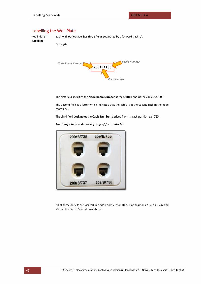
Labelling Standards APPENDIX A
45 IT Services | Telecommunications Cabling Specification & Standard v.2.1 | University of Tasmania | Page 45 of 54
Labelling the Wall Plate Wall Plate
Labelling:
Each wall outlet label has three fields separated by a forward slash '/'.
Example:
The first field specifies the Node Room Number at the OTHER end of the cable e.g. 209
The second field is a letter which indicates that the cable is in the second rack in the node
room i.e. B
The third field designates the Cable Number, derived from its rack position e.g. 735.
The image below shows a group of four outlets:
All of these outlets are located in Node Room 209 on Rack B at positions 735, 736, 737 and
738 on the Patch Panel shown above.
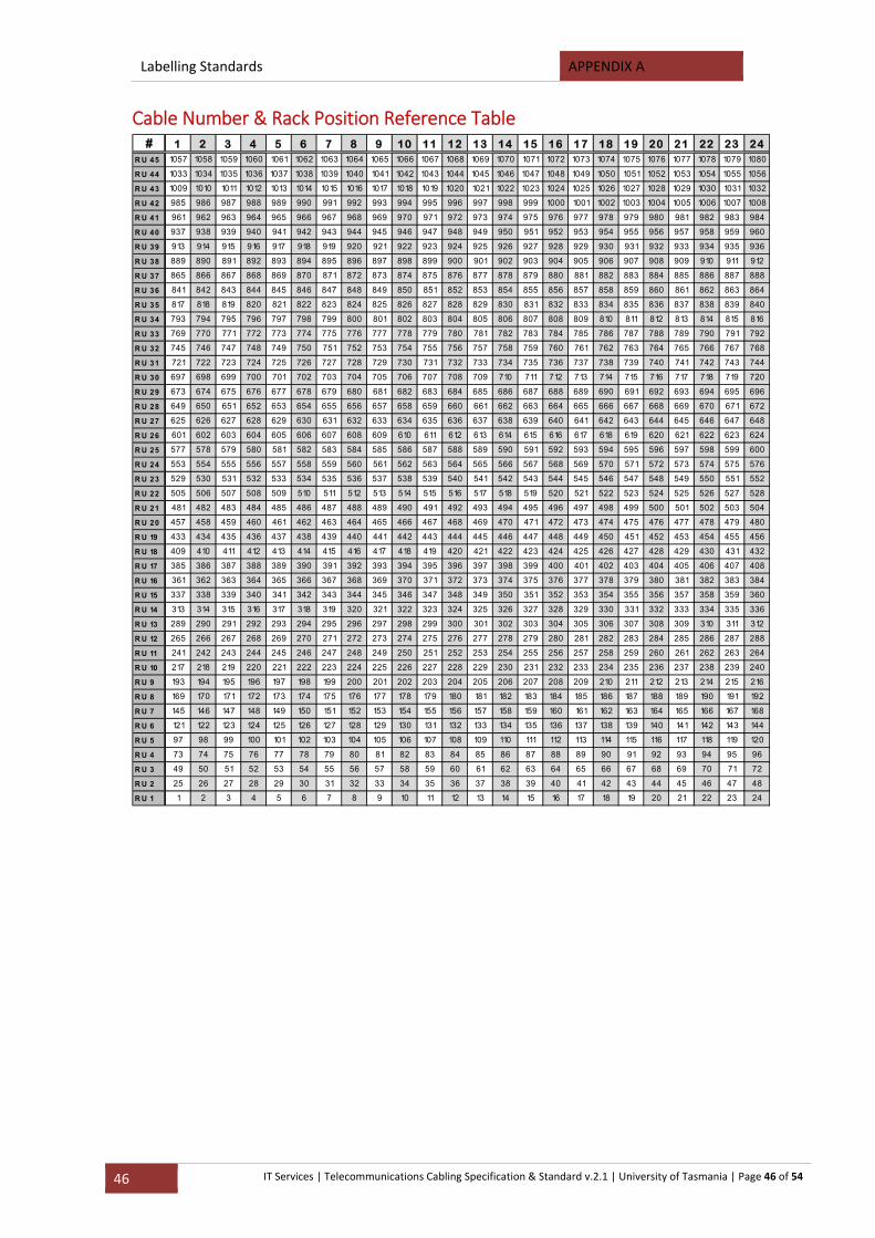
Labelling Standards APPENDIX A
46 IT Services | Telecommunications Cabling Specification & Standard v.2.1 | University of Tasmania | Page 46 of 54
Cable Number & Rack Position Reference Table # 1 2 3 4 5 6 7 8 9 10 11 12 13 14 15 16 17 18 19 20 21 22 23 24
R U 45 1057 1058 1059 1060 1061 1062 1063 1064 1065 1066 1067 1068 1069 1070 1071 1072 1073 1074 1075 1076 1077 1078 1079 1080
R U 44 1033 1034 1035 1036 1037 1038 1039 1040 1041 1042 1043 1044 1045 1046 1047 1048 1049 1050 1051 1052 1053 1054 1055 1056
R U 43 1009 1010 1011 1012 1013 1014 1015 1016 1017 1018 1019 1020 1021 1022 1023 1024 1025 1026 1027 1028 1029 1030 1031 1032
R U 42 985 986 987 988 989 990 991 992 993 994 995 996 997 998 999 1000 1001 1002 1003 1004 1005 1006 1007 1008
R U 41 961 962 963 964 965 966 967 968 969 970 971 972 973 974 975 976 977 978 979 980 981 982 983 984
R U 40 937 938 939 940 941 942 943 944 945 946 947 948 949 950 951 952 953 954 955 956 957 958 959 960
R U 39 913 914 915 916 917 918 919 920 921 922 923 924 925 926 927 928 929 930 931 932 933 934 935 936
R U 38 889 890 891 892 893 894 895 896 897 898 899 900 901 902 903 904 905 906 907 908 909 910 911 912
R U 37 865 866 867 868 869 870 871 872 873 874 875 876 877 878 879 880 881 882 883 884 885 886 887 888
R U 36 841 842 843 844 845 846 847 848 849 850 851 852 853 854 855 856 857 858 859 860 861 862 863 864
R U 35 817 818 819 820 821 822 823 824 825 826 827 828 829 830 831 832 833 834 835 836 837 838 839 840
R U 34 793 794 795 796 797 798 799 800 801 802 803 804 805 806 807 808 809 810 811 812 813 814 815 816
R U 33 769 770 771 772 773 774 775 776 777 778 779 780 781 782 783 784 785 786 787 788 789 790 791 792
R U 32 745 746 747 748 749 750 751 752 753 754 755 756 757 758 759 760 761 762 763 764 765 766 767 768
R U 31 721 722 723 724 725 726 727 728 729 730 731 732 733 734 735 736 737 738 739 740 741 742 743 744
R U 30 697 698 699 700 701 702 703 704 705 706 707 708 709 710 711 712 713 714 715 716 717 718 719 720
R U 29 673 674 675 676 677 678 679 680 681 682 683 684 685 686 687 688 689 690 691 692 693 694 695 696
R U 28 649 650 651 652 653 654 655 656 657 658 659 660 661 662 663 664 665 666 667 668 669 670 671 672
R U 27 625 626 627 628 629 630 631 632 633 634 635 636 637 638 639 640 641 642 643 644 645 646 647 648
R U 26 601 602 603 604 605 606 607 608 609 610 611 612 613 614 615 616 617 618 619 620 621 622 623 624
R U 25 577 578 579 580 581 582 583 584 585 586 587 588 589 590 591 592 593 594 595 596 597 598 599 600
R U 24 553 554 555 556 557 558 559 560 561 562 563 564 565 566 567 568 569 570 571 572 573 574 575 576
R U 23 529 530 531 532 533 534 535 536 537 538 539 540 541 542 543 544 545 546 547 548 549 550 551 552
R U 22 505 506 507 508 509 510 511 512 513 514 515 516 517 518 519 520 521 522 523 524 525 526 527 528
R U 21 481 482 483 484 485 486 487 488 489 490 491 492 493 494 495 496 497 498 499 500 501 502 503 504
R U 20 457 458 459 460 461 462 463 464 465 466 467 468 469 470 471 472 473 474 475 476 477 478 479 480
R U 19 433 434 435 436 437 438 439 440 441 442 443 444 445 446 447 448 449 450 451 452 453 454 455 456
R U 18 409 410 411 412 413 414 415 416 417 418 419 420 421 422 423 424 425 426 427 428 429 430 431 432
R U 17 385 386 387 388 389 390 391 392 393 394 395 396 397 398 399 400 401 402 403 404 405 406 407 408
R U 16 361 362 363 364 365 366 367 368 369 370 371 372 373 374 375 376 377 378 379 380 381 382 383 384
R U 15 337 338 339 340 341 342 343 344 345 346 347 348 349 350 351 352 353 354 355 356 357 358 359 360
R U 14 313 314 315 316 317 318 319 320 321 322 323 324 325 326 327 328 329 330 331 332 333 334 335 336
R U 13 289 290 291 292 293 294 295 296 297 298 299 300 301 302 303 304 305 306 307 308 309 310 311 312
R U 12 265 266 267 268 269 270 271 272 273 274 275 276 277 278 279 280 281 282 283 284 285 286 287 288
R U 11 241 242 243 244 245 246 247 248 249 250 251 252 253 254 255 256 257 258 259 260 261 262 263 264
R U 10 217 218 219 220 221 222 223 224 225 226 227 228 229 230 231 232 233 234 235 236 237 238 239 240
R U 9 193 194 195 196 197 198 199 200 201 202 203 204 205 206 207 208 209 210 211 212 213 214 215 216
R U 8 169 170 171 172 173 174 175 176 177 178 179 180 181 182 183 184 185 186 187 188 189 190 191 192
R U 7 145 146 147 148 149 150 151 152 153 154 155 156 157 158 159 160 161 162 163 164 165 166 167 168
R U 6 121 122 123 124 125 126 127 128 129 130 131 132 133 134 135 136 137 138 139 140 141 142 143 144
R U 5 97 98 99 100 101 102 103 104 105 106 107 108 109 110 111 112 113 114 115 116 117 118 119 120
R U 4 73 74 75 76 77 78 79 80 81 82 83 84 85 86 87 88 89 90 91 92 93 94 95 96
R U 3 49 50 51 52 53 54 55 56 57 58 59 60 61 62 63 64 65 66 67 68 69 70 71 72
R U 2 25 26 27 28 29 30 31 32 33 34 35 36 37 38 39 40 41 42 43 44 45 46 47 48
R U 1 1 2 3 4 5 6 7 8 9 10 11 12 13 14 15 16 17 18 19 20 21 22 23 24
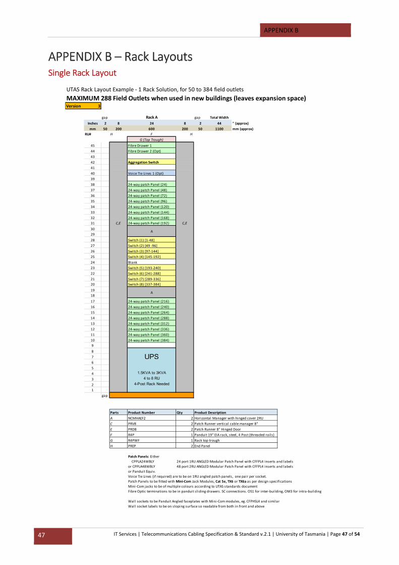
APPENDIX B
47 IT Services | Telecommunications Cabling Specification & Standard v.2.1 | University of Tasmania | Page 47 of 54
APPENDIX B – Rack Layouts Single Rack Layout
UTAS Rack Layout Example ‐ 1 Rack Solution, for 50 to 384 field outlets
MAXIMUM 288 Field Outlets when used in new buildings (leaves expansion space)Version 3
gap Rack A gap Total Width
Inches 2 8 24 8 2 44 " (approx)
mm 50 200 600 200 50 1100 mm (approx)
RU# H F H
G (Top Trough)
45 Fibre Drawer 1
44 Fibre Drawer 2 (Opt)
43
42 Aggregation Switch
41
40 Voice Tie Lines 1 (Opt)
39
38 24‐way patch Panel (24)
37 24‐way patch Panel (48)
36 24‐way patch Panel (72)
35 24‐way patch Panel (96)
34 24‐way patch Panel (120)
33 24‐way patch Panel (144)
32 24‐way patch Panel (168)
31 C,E 24‐way patch Panel (192) C,E
30
29
28 Switch (1) [1‐48]
27 Switch (2) [49 ‐96]
26 Switch (3) [97‐144]
25 Switch (4) [145‐192]
24 Blank
23 Switch (5) [193‐240]
22 Switch (6) [241‐288]
21 Switch (7) [289‐336]
20 Switch (8) [337‐384]
19
18
17 24‐way patch Panel (216)
16 24‐way patch Panel (240)
15 24‐way patch Panel (264)
14 24‐way patch Panel (288)
13 24‐way patch Panel (312)
12 24‐way patch Panel (336)
11 24‐way patch Panel (360)
10 24‐way patch Panel (384)
9
8
7 UPS6
5
4 1.5KVA to 3KVA
3 4 to 8 RU
2 4-Post Rack Needed
1
gap
Parts Product Number Qty
A NCMHAEF2 2
C PRV8 2
E PRD8 2
F R4P 1
G R4PWF 1
H PREP 2
Patch Panels: Either
CPPLA24WBLY 24 port 1RU ANGLED Modular Patch Panel with CFFPL4 inserts and labels
or CPPLA48WBLY 48 port 2RU ANGLED Modular Patch Panel with CFFPL4 inserts and labels
or Panduit Equiv.
Voice Tie Lines (if required) are to be on 1RU angled patch panels, one pair per socket.
Patch Panels to be fitted with Mini‐Com Jack Modules, Cat 5e, TX6 or TX6a as per design specifications
Mini‐Com jacks to be of multiple colours according to UTAS standards document
Fibre Optic terminations to be in panduit sliding drawers. SC connections. OS1 for inter‐building, OM3 for intra‐building
Wall sockets to be Panduit Angled faceplates with Mini‐Com modules, eg. CFPHSL4 and similar
Wall socket labels to be on sloping surface so readable from both in front and above
A
Panduit 19" EIA rack, steel, 4 Post (threaded rai ls)
Rack top trough
End Panel
A
Product Description
Horizontal Manager with hinged cover 2RU
Patch Runner vertical cable manager 8"
Patch Runner 8" Hinged Door
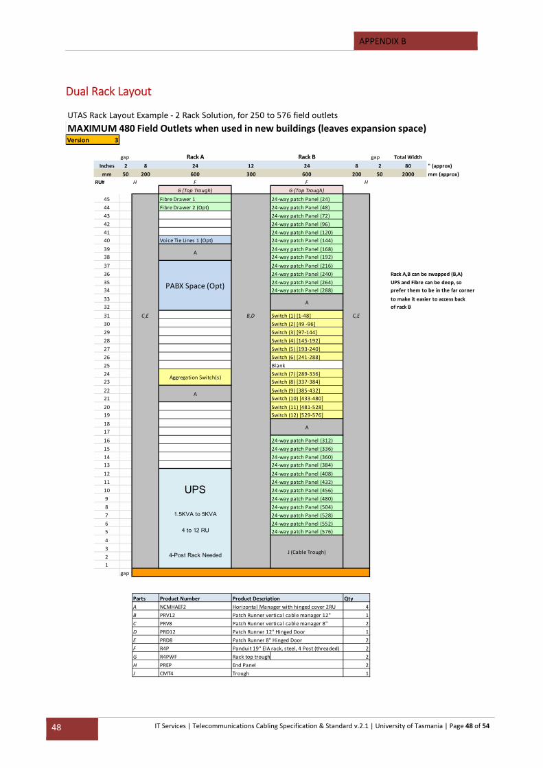
APPENDIX B
48 IT Services | Telecommunications Cabling Specification & Standard v.2.1 | University of Tasmania | Page 48 of 54
Dual Rack Layout
UTAS Rack Layout Example ‐ 2 Rack Solution, for 250 to 576 field outlets
MAXIMUM 480 Field Outlets when used in new buildings (leaves expansion space)Version 3
gap Rack A Rack B gap Total Width
Inches 2 8 24 12 24 8 2 80 " (approx)
mm 50 200 600 300 600 200 50 2000 mm (approx)
RU# H F F H
G (Top Trough) G (Top Trough)
45 Fibre Drawer 1 24‐way patch Panel (24)
44 Fibre Drawer 2 (Opt) 24‐way patch Panel (48)
43 24‐way patch Panel (72)
42 24‐way patch Panel (96)
41 24‐way patch Panel (120)
40 Voice Tie Lines 1 (Opt) 24‐way patch Panel (144)
39 24‐way patch Panel (168)
38 24‐way patch Panel (192)
37 24‐way patch Panel (216)
36 24‐way patch Panel (240) Rack A,B can be swapped (B,A)
35 24‐way patch Panel (264) UPS and Fibre can be deep, so
34 24‐way patch Panel (288) prefer them to be in the far corner
33 to make it easier to access back
32 of rack B
31 C,E B,D Switch (1) [1‐48] C,E
30 Switch (2) [49 ‐96]
29 Switch (3) [97‐144]
28 Switch (4) [145‐192]
27 Switch (5) [193‐240]
26 Switch (6) [241‐288]
25 Blank
24 Switch (7) [289‐336]
23 Switch (8) [337‐384]
22 Switch (9) [385‐432]
21 Switch (10) [433‐480]
20 Switch (11) [481‐528]
19 Switch (12) [529‐576]
18
17
16 24‐way patch Panel (312)
15 24‐way patch Panel (336)
14 24‐way patch Panel (360)
13 24‐way patch Panel (384)
12 24‐way patch Panel (408)
11 24‐way patch Panel (432)
10 24‐way patch Panel (456)
9 24‐way patch Panel (480)
8 24‐way patch Panel (504)
7 1.5KVA to 5KVA 24‐way patch Panel (528)
6 24‐way patch Panel (552)
5 24‐way patch Panel (576)
4
3
2
1
gap
Parts Product Number Product Description Qty
A NCMHAEF2 Horizontal Manager with hinged cover 2RU 4
B PRV12 Patch Runner vertical cable manager 12" 1
C PRV8 Patch Runner vertical cable manager 8" 2
D PRD12 Patch Runner 12" Hinged Door 1
E PRD8 Patch Runner 8" Hinged Door 2
F R4P Panduit 19" EIA rack, steel, 4 Post (threaded) 2
G R4PWF Rack top trough 2
H PREP 2
J CMT4 1
A
A
Trough
UPS
PABX Space (Opt)
4 to 12 RU
J (Cable Trough)4-Post Rack Needed
End Panel
Aggregation Switch(s)
A
A

APPENDIX B
49 IT Services | Telecommunications Cabling Specification & Standard v.2.1 | University of Tasmania | Page 49 of 54
Single Rack Floor Plan
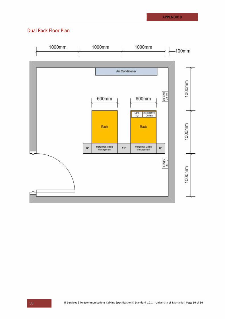
APPENDIX B
50 IT Services | Telecommunications Cabling Specification & Standard v.2.1 | University of Tasmania | Page 50 of 54
Dual Rack Floor Plan
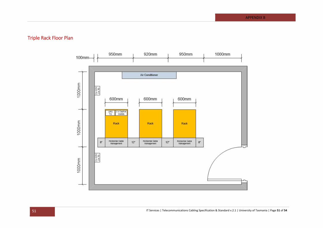
APPENDIX B
51 IT Services | Telecommunications Cabling Specification & Standard v.2.1 | University of Tasmania | Page 51 of 54
Triple Rack Floor Plan
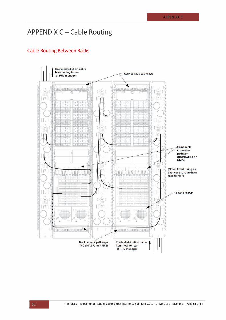
APPENDIX C
52 IT Services | Telecommunications Cabling Specification & Standard v.2.1 | University of Tasmania | Page 52 of 54
APPENDIX C – Cable Routing
Cable Routing Between Racks
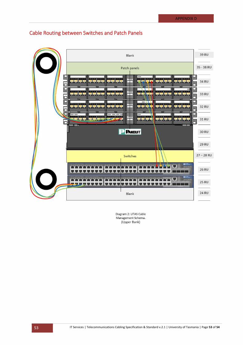
APPENDIX D
53 IT Services | Telecommunications Cabling Specification & Standard v.2.1 | University of Tasmania | Page 53 of 54
Cable Routing between Switches and Patch Panels
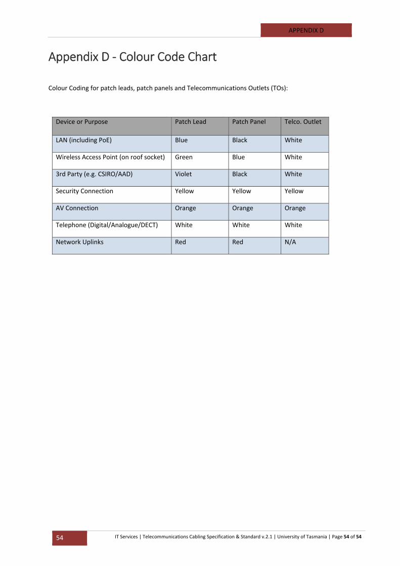
APPENDIX D
54 IT Services | Telecommunications Cabling Specification & Standard v.2.1 | University of Tasmania | Page 54 of 54
Appendix D ‐ Colour Code Chart
Colour Coding for patch leads, patch panels and Telecommunications Outlets (TOs):
Device or Purpose Patch Lead Patch Panel Telco. Outlet
LAN (including PoE) Blue Black White
Wireless Access Point (on roof socket) Green Blue White
3rd Party (e.g. CSIRO/AAD) Violet Black White
Security Connection Yellow Yellow Yellow
AV Connection Orange Orange Orange
Telephone (Digital/Analogue/DECT) White White White
Network Uplinks Red Red N/A