influence of the interface condition on stress...
TRANSCRIPT

Abridgment
Influence of the Interface Condition on Stress Distribution in a Layered System
J. Uzan, Technion, Israel Institute of Technology, Haifa
The current practice in pavement design generally assumes rough interfaces in flexible pavements and smooth interfaces in rigid pavements. Field observations have shown that friction at the interfaces exists but is at different levels.
In this paper, the behavior of a system containing a number of homogeneous, isotropic, linear-elastic layers is analyzed using a linear frictional model to simulate the real behavior at the interfaces. The usefulness of the model is illustrated by the cases of a flexible pavement and of an overlay of a rigid pavement. The numerical results refer only to the vertical loading case.
MODEL OF FRICTION AT INTERFACES
The interface is considered to be a layer of finite thickness (h), on which a pure shear stress (r) is applied. The distortion (Y) for an elastic medium is given by
T= G-y (I)
where G is the shear modulus of the interface material. For small displacements, the distortion is defined as
'Y = L'rn/h (2)
priate in the framework of the linear-elastic layered system. For simplicity in the computations, K is expressed through the parameter .t as follows:
K=Q/(1-Q) (4)
The value of l = 1 for which K is infinite describes the rough interface condition and the value of l = 0 for which K is zero describes the smooth interface condition. Eshed (private communication) has conducted direct shear tests on two blocks of asphalt concrete at 25°C, and found K to be about 500 to 1000 kg/cm3
•
THEORETICAL BACKGROUND
The problem is formulated for a uniformly distributed circular load applied vertically on the top of the first layer. The derivation of the stress and displacement equations follows thatofMuki (1) and Schiffman (2). These equations were verified with Vertstraten's equations (3, 4,) for smooth and rough interfaces. - The application of the partially rough interface condi
tion leads to the following modified boundary conditions:
(5)
where au is the relative displacement between the two and sides of the interface. Hence,
T = G/h L'rn = KL'.u (3)
where K is the modulus of resistance to displacements of the interface and can be determined from laboratory put,e shear tests. In the following discussion, K is considered to be an intrinsic property of the interface, independent of its thickness. The value of K is assumed to be constant, i.e., it is unaffected by normal loads or relative displacement rates. This assumption is appro-
Publication of this paper sponsored by Committee on Mechanics of Earth Masses and Layered Systems.
(6)
where
a.,.1 and a0z,i = shear stresses at the bottom of the i th layer, i.e., at the depth of interface i (i = 1, 2, ... , n - 1);
a.,,1., and a8
z,1+i = shear sfresses at the top of the (i+l) th layer, i.e., at the depth of interface i;
u, .• and u •. 1 = radial and tangential displacement at the bottom of the i th layer; and
.f,1 = property of interface i (defined by equation 4).
These boundary conditions led to a modified set of linear equations, which were solved by a computer pro-
71
72
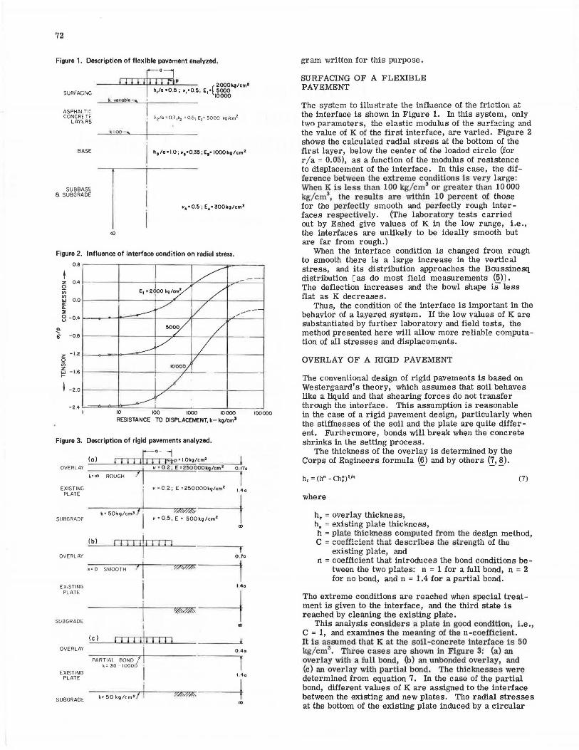
Figure 1. Description of flexible pavement analyzed.
SURFACING
ASPHALTIC CONCRETE
LAYERS
BASE
SUBBASE a SUBGRADE
ll.=003
..... • 0.5; E4 • 300ko/cm 1
Figure 2. Influence of interface condition on radial stress.
0.8 r-----i----,----.----::r-----,
.. .... b" -0.8 1-----+----l---,IL- - I
z -1 .2 1-----i.-...-::::::....-1----+l---+----I 0 u; ~ - 1,61----t----+---+-"---f-
~ -2.01----+---+-+------1-------1
-2.4 L==:11=>i=;:1,===~_i ___ ....._ ___ l_ _ __ _J I 10 100 IOOO 10 000
RESISTANCE TO DISPLACEMENT, k-kg/cm3
Figure 3. Description of rigid pavements analyzed.
OVERLAY
EXISTING PLATE
SUBGRADE
OVERLAY
EXISTING PLATE
SUB GRADE
OVERLAY
EXISTING PLATE
SUBGRADE
(o) 1 0--j
rTTTJJ-T"CCB• • 1.0k21c,._,m,..• ______ _.
I v • 0.2 : E • 250000t9/cm•
ROUGH f 0~ 17a
I • • 0 .2 ~ E •250000k9/cm• I 4o
I ?,<W°/.(<S: k•50kg/cm• I
v • 0 .5; E • 500kg/cm2
<D
(bl I Ill
k• 0 SMOOTH 'I I
0 ,70
-----...-+---~v~~~~,.....~----~,
140
---i-~w~--i 1 I <D
(c) I I I I ii I 11 I l
PARTIAL BOND I I k= 30- IOOOO
i k• 50 kg/cm•J i
0 .40
l l.4a
-----.-+---r,~~~v~~ ----~ <D
100000
gram written for this purpose.
SURFACING OF A FLEXIBLE PAVEMENT
The system to illustrate the influence of the friction at the interface is shown in Figure 1. In this system, only two parameters, the elastic modulus of the surfacing and the value of K of the first interface, are varied. Figure 2 shows the calculated radial stress at the bottom of the first layer, below the center of the loaded circle (for r/a = 0.05), as a function of the modulus of resistence to displacement of the interface. In this case, the difference between the extreme conditions is very large: When K is less than 100 kg/ cm3 or greater than 10 000 kg/cm3
, the results are within 10 pe1·cent of those for the perfectly smooth and perfectly rough inter -faces respectively. (The laboratory tests carried out by Eshed give values of K in the low range, i.e., the interfaces are unlikely to be ideally smooth but are far from rough.)
When the interface condition is changed from rough to smooth there is a large increase in the vertical stress, and its distribution approaches the Boussinesq distribution [as do most field measurements (5)1. The deflection increases and the bowl shape is less flat as K decreases.
Thus, the condition of the interface is important in the behavior of a layered system. If the low values of K are substantiated by further laboratory and field tests, the method presented here will allow more reliable computation of all stresses and displacements.
OVERLAY OF A RIGID PAVEMENT
The conventional design of rigid pavements is based on Westergaard's theory, which assumes that soil behaves like a liquid and that shearing forces do not transfer through the interface. This assumption is reasonable in the case of a rigid pavement design, particularly when the stiffnesses of the soil and the plate are quite different. Furthermore, bonds will break when the concrete shrinks in the setting process.
The thickness of the overlay is determined by the Corps of Engineers formula (~) and by others (2, !!_).
h, = (h" - Ch~)t/n
where
h. = overlay thickness, h
0 = existing plate thickness,
(7)
h =plate thickne~s computed from the design method, C = coefficient that describes the strength of the
existing plate, and n = coefficient that introduces the bond conditions be
tween the two plates: n = 1 for a full bond, n = 2 for no bond, and n = 1.4 for a partial bond.
The extreme conditions are reached when special treatment is given to the interface, and the third state is reached by cleaning the existing plate.
This analysis considers a plate in good condition, i.e., C = 1, and examines the meaning of then-coefficient. It is assumed. that K at the soil-concrete interface is 50 kg/cm3
• Three cases are shown in Figure 3: (a) an overlay with a full bond, (b) an unbonded overlay, and (c) an overlay with partial bond. The thicknesses were determined from equation 7. In the case of the partial bond, different values of K are assigned to the interface between the existing and new plates. The radial stresses at the bottom of the existing plate induced by a circular

load at the surface are summarized below.
Case K(kg/cm3 ) u,lp Case K(kg/cm3 ) u,/p
a 00 1.82 c 330 2.10 b 0 1.87 c 1 000 2.06 c 32 2.11 c 10000 1.86 c 100 2.11 c 1.66
The stress level is equal in all three cases when K is 10 000 kg/cm3
•
This value is very large, and it should be considered that shrinkage due to chemical processes and bending due to temperature gradients during the setting of the concrete will break any weak bond between the two plates. Such large values of K may not develop without special treatment of the interface. The overstress in the unbonded case, i.e., when K < 330 kg/cm3
, as compared to that in the partially bonded case, when K = 10 000 kg/ cm3
, is about 15 percent; it is difficult to detect such a small overstress in field measurements.
SUMMARY AND CONCLUSIONS
The results of the computations emphasize the influence of the interface condition on the stress distribution and hence on the design of pavements. In flexible pavements, the radial stress is strongly affected by the interface condition. The vertical stress and the deflection bowl are also affected, but to a smaller extent. Since the rational design of flexible pavements is based on the radial stress or strain at the bottom of the asphaltconcrete layer and on the vertical stress or strain at the top of the subgrade, the determination and use in design of the modulus of resistance to displacement between different layers should improve the design system and make it more realistic.
In rigid pavement overlays also, the condition of the interface between the existing and the new surface is important. In the case analyzed, the partial bond (as defined by the Corps of Engineers) corresponds to a large value of the modulus of resistance to displacement. Since the existence of such a large value is questionable, the determination of realistic values will make the design of overlays more rational.
ACKNOWLEDGMENT
I wish to acknowledge Robert L. Lytton of Texas A&M University, who has reviewed the paper and made corrections.
REFERENCES
1. R. Muki. Asymmetric Problems of the Theory of Elasticity for a Semi-Infinite Solid and Thick Plate. Progress in Solid Mechanics, Vol. 1, 1960, pp. 400-439.
2. R. L. Schiffman. General Analysis of Stresses and Displacements in Layered Elastic Systems. Proc., 1st International Conference on the Structural Design of Asphalt Pavements, Ann Arbor, Mich., 1962, pp. 365-375.
3. J. Verstraten. Contraintes et deplacements dans les systemes multicouches elastiques. Centre de Recherches Routieres, Bruxelles, Rapport de Recherche No. 132/ JV / 1966, 1966.
4. J. Verstraten. Stresses and Displacements in Elastic Layered Systems. Proc., 2nd International Conference on the Structural Design of Asphalt Pavements, Ann Arbor, Mich., 1967, pp. 277-290.
5. A. S. Vesic and L. Domaschuk. Theoretical Anal-
6.
7.
ysis of Structural Behavior of Road Test Flexible Pavements. NCHRP, Rept. 10, 1964. Rigid Airfield Pavements, Engineering and Design Manual. U.S. Department of the Army, EM 1110-45-303, 1958.
73
G. Moraldi. Developments of Pavement Design Both Rigid and Flexible on the Continent of Europe. Aircraft Pavement Design, Proc., Symposium of the Institute of Civil Engineers, London, 1971, pp. 55-64.
8. R. G. Packard. Design of Concrete Airport Pavement. Portland Cement Assoc., 1973.