influence of different anchoring groups in indoline dyes for dye-sensitized solar cells: electron...
TRANSCRIPT

at SciVerse ScienceDirect
Journal of Power Sources 234 (2013) 139e146
Contents lists available
Journal of Power Sources
journal homepage: www.elsevier .com/locate/ jpowsour
Influence of different anchoring groups in indoline dyes for dye-sensitized solarcells: Electron injection, impedance and charge recombination
Bo Liu a,c,1, Wenqin Li b,1, Bao Wang a, Xiaoyan Li a, Qingbin Liu a,**, Yoshinori Naruta c, Weihong Zhu b,*
aCollege of Chemistry and Material Science, Hebei Normal University, No. 20, East Road of Nan Er Huan, Shijiazhuang 050023, PR Chinab Shanghai Key Laboratory of Functional Materials Chemistry, Key Laboratory for Advanced Materials, Institute of Fine Chemicals, East China University of Science & Technology,130 Meilong Road, Shanghai 200237, PR Chinac Institute for Materials Chemistry and Engineering and International Institute for Carbon-Neutral Energy Research (WPI-I2CNER), Kyushu University, Fukuoka 812-8581, Japan
h i g h l i g h t s
* Corresponding author. Tel.: þ86 21 6425 0772; fa** Corresponding author.
E-mail addresses: [email protected] (Q. Liu), wh1 These authors contributed equally to this work.
0378-7753/$ e see front matter � 2013 Elsevier B.V.http://dx.doi.org/10.1016/j.jpowsour.2013.01.152
g r a p h i c a l a b s t r a c t
< The influence of different anchoringgroups on photovoltaic perfor-mances is focused.
< The photovoltaic efficiency of C-RA(0.57e0.90%) is much less than thatof C-CA (8.49%).
< The low photo-excited electron in-jection efficiency in C-RA results inlow JSC.
< Both low charge density and fastrecombination rate in C-RA lead tolow VOC.
a r t i c l e i n f o
Article history:Received 24 July 2012Received in revised form24 November 2012Accepted 25 January 2013Available online 7 February 2013
Keywords:Solar cellsIndolineRhodanineAcceptorCharge recombination
a b s t r a c t
For developing panchromatic dyes, we focus on the effect of rhodanine acceptor on photovoltaic per-formances in D-p-A indoline dye. Upon changing from cyanoacetic acid (dye C-CA) to rhodanine-3-aceticacid (dye C-RA) as acceptor and anchoring group, C-RA shows broader absorption band, which canoverlap with the solar spectrum more preferably. However, the power conversion efficiency of DSSCsbased on C-RA (0.57e0.90%) is one order of magnitude with respect to C-CA (8.49%). The distinct dif-ference of IPCE values between C-CA and C-RA is predominately attributed to the different excitedelectron injection yield (Finj). The relatively short excited electron lifetime and the isolation of LUMOorbital from anchoring group in C-RA result in the low photo-excited electron injection efficiency withlow JSC. Moreover, with respect to C-CA, the systematic SLIT and EIS studies demonstrate that C-RApossesses the relatively low injection charge density in the TiO2 electrode and fast charge recombinationrate, leading to a low VOC. Our studies are highly helpful to the design of novel metal-free D-p-A organicsensitizers, especially for those using rhodanine-3-acetic acid as acceptor.
� 2013 Elsevier B.V. All rights reserved.
x: þ86 21 6425 2758.
[email protected] (W. Zhu).
All rights reserved.
1. Introduction
Dye-sensitized solar cells (DSSCs) have attracted considerableattention due to their high performance and the potential of low-cost production [1e5]. As a critical component in DSSCs, metal-free organic sensitizers have been extensively explored in recentyears due to their low material costs, ease of structural mod-ification, high molar extinction coefficients, and environment-friendly characteristics [6e10]. Among them, indoline dyes have

B. Liu et al. / Journal of Power Sources 234 (2013) 139e146140
become a kind of the most promising organic sensitizers [11,12].However, their power conversion efficiencies (h) are still lower thanthose of classic ruthenium dyes [13e15]. One of the most importantdrawbacks is their relatively narrow absorption spectra in visibleregion, a stumbling block in the enhancement of short-circuitphotocurrent density (JSC) [16]. Accordingly, many efforts havefocused on developing panchromatic photo-responsive indolinebased sensitizers [17e22]. The first indoline dye, coded as D102,was synthesized by Horiuchi et al. in 2003 [11]. Its maximum peak(lmax) was found at 491 nm in a mixture solution of t-butyl alcohol/acetonitrile, and the onset wavelength was at about 600 nm. Toincrease the light harvesting capability, an additional rhodanineunit was introduced into acceptor to develop dyes D149 and D205[17,19]. Compared to D102, the lmax and the onset wavelength ofD149 were successfully red-shifted to 526 and 650 nm, respec-tively, resulting in a sharply increase in photovoltaic efficiency (h).
With our continuous interests in indoline sensitizers [23e29], weare also intrigued to expand the photo-responsive area to wholevisible region, even to near-infrared region (NIR). More recently, wehave introducedanadditional carbazoleunit into indolinesegment (C-CA), resulting in a broad absorption spectrumcovered fromultravioletregion to 763 nm [29]. However, its absorbance as well as IPCE valuesinNIR region is still low.Moreover, its absorbance inorganic solvents islower than 5% ofmaximumvalue in the region of longer than 690 nm,meaning that C-CA is not a practically panchromatic sensitizer.
With these in mind, a novel donor-p-acceptor (D-p-A) indolinedye, coded as C-RA (Scheme 1), is developed by applying rhoda-nine-3-acetic acid as the acceptor unit, making it as a panchromaticsensitizer in the true sense. As expected, the absorption of C-RAbecomes very broad in visible region, being capable of extending to800 nm in CH3CN/CH2Cl2 (3/2 v/v). When adsorbed onto 12 mmTiO2 electrode, its onset wavelength is even extended to about940 nm in NIR region, showing a preferable overlap with solar lightspectrum. However, the plateau IPCE value of C-RA-sensitizedDSSCs was only around 10% with an unexpected low power con-version efficiency (0.57e0.90%), one order of magnitude as C-CA(8.49%) under simulated AM 1.5 irradiation. Herein, we are aimed tosystematically investigate the distinct difference in photovoltaicperformances upon changing the acceptor from cyanoacetic acid(C-CA) to rhodanine-3-acetic acid (C-RA). Considering the prefer-ably broad light-harvesting abilities of C-RA in visible and near-IRregion, we carried out the excited electron lifetime measurementand the density functional theory (DFT) calculation to take insightinto the poor performance, especially for the relatively low JSC.Meanwhile, the stepped light-induced transient (SLIT) and elec-trochemical impedance spectroscopy (EIS) measurements wereperformed on C-CA and C-RA sensitized DSSCs to investigate thecharge recombination lifetimes. These studies are highly desirableto the design of novel metal-free organic D-p-A sensitizers, espe-cially for the dyes using rhodanine-3-acetic acid as acceptor.
2. Experimental
2.1. General
The FTO conducting glass (fluorine doped SnO2, sheetresistance < 15 U/square, transmission > 90% in the visible) was
N
SN
C-CA
COOH
CNN
SN
C-RA
N
S
O
S
COOH
Scheme 1. Chemical structures of C-CA and C-RA with different anchoring groups.
obtained from Geao Science and Educational Co. Ltd., China. tert-Butylpyridine (TBP) was purchased from Aldrich. Titanium tetra-chloride, lithium iodide, 1-butyl-3-methylimidazolium iodide, anddeoxycholic acid (DCA)were purchased fromWako Ltd. and used asreceived. TiO2 paste (PST-18NR for 20 nm and PST-400C for400 nm) was provided by JGC C&C Ltd. All other chemicals wereproduced by Alfa Aesar and used without further purification.
2.2. Characterization
1H NMR and 13C NMR spectra were obtained with a Bruker AVIII-500 spectrometer using tetramethylsilane as internal standard.High-resolution mass spectra (HRMS) were recorded on a JEOLLMS-HX-110 spectrometer with 3-nitrobenzyl alcohol (NBA) asa matrix. UVevisible spectra were determined with a ShimadzuUV-2501PC spectrometer. Fluorescent spectra were recorded onHitachi F-4600 spectrometer. In the measurement of absorptionspectra of dye-loaded TiO2 electrode, the obvious p-aggregationappeared even on the electrode as thin as 4 mm. The aggregationcan broaden the absorption spectrum, and cover the absorptionpeaks. Therefore, in these measurements, 30 mM DCA was addedinto 0.3 mM dye solution for preventing aggregation. The cyclicvoltammograms were measured on a CHI660B electrochemicalworkstation (CH Instruments) using a normal three-electrodes cellwith a dye-loaded TiO2 electrode as working electrode, a Pt wireauxiliary electrode, and Ag/AgCl reference electrode in saturatedKCl solution, 0.1 M tetrabutylammonium hexafluorophosphoricwas used as supporting electrolyte. After the measurement, ferro-cene was added as the internal reference for calibration.
2.3. Synthesis
C-RA was synthesized according to our previous report exceptusing rhodanine-3-acetic acid instead of cyanoacetic acid [29]. Theproduct was obtained as dark purple solid through column chro-matography over silica gel with CH2Cl2/CH3OH mixture (15:1) andrecrystallization in CH2Cl2/petroleum ether (yield, 47%). 1H NMR(500 MHz, d6-DMSO, ppm): d 8.16 (d, J ¼ 7.5 Hz, 1H), 8.10 (s, 1H),8.00 (s, 1H), 7.69 (d, J¼ 4.0 Hz,1H), 7.58e7.62 (m, 2H), 7.41e7.47 (m,3H), 7.22e7.28 (m, 3H), 7.13e7.19 (m, 2H), 6.61 (d, J ¼ 8.0 Hz, 1H),5.01 (t, J ¼ 8.5 Hz, 1H), 4.48 (s, 2H), 4.38 (t, J ¼ 6.5 Hz, 2H), 3.86 (t,J ¼ 8.5 Hz, 1H), 2.00e2.11 (m, 1H), 1.61e1.86 (m, 6H), 1.37e1.53 (m,1H), 1.26e1.35 (m, 4H), 0.83 (t, J ¼ 7.0 Hz, 3H). 13C NMR (125 MHz,d6-DMSO, ppm): d 192.2, 166.8, 153.6, 150.6, 141.0, 138.1, 137.3,135.6, 134.8, 133.9, 133.1, 129.0, 127.2, 126.4, 126.3, 126.1, 123.2,122.2, 121.8, 121.0, 119.0, 118.3, 116.1, 114.8, 110.4, 109.7, 106.0, 70.2,47.9, 45.0, 42.8, 35.6, 33.3, 29.2, 28.8, 24.4, 22.4, 14.3. HRMS (TOFMS ESþ): m/z calcd for C40H38N3O3S3 [M þ H]þ 704.2075, found704.2078.
2.4. Fabrication of solar cells
12 mm Nanocrystalline TiO2 electrodes with 4 mm scatteringlayer were prepared and modified following the reported proce-dure [30]. The thickness of TiO2 film was measured by a surfaceprofiler (Dektak Co., Ltd., Model DAKTAK II). The dye-loaded elec-trodes were prepared by dipping TiO2 electrodes (1.2 cm � 0.8 cm)into 0.3 mM dye solution (CHCl3/C2H5OH ¼ 3/2) with differentconcentrations of DCA for 5 h. To prepare the counter electrode, thePt catalyst was deposited on the cleaned FTO glass by coating witha drop of H2PtCl6 solution (0.02 M in 2-propanol solution) with theheat treatment at 500 �C for 30 min. In this work, two kinds ofelectrolytes were used: A) 0.6 M 1-butyl-3-methylimidiazoliumiodide (BMII), 0.1 M LiI, 0.05 M I2 and 0.6 M tert-butylpyridine(TBP) in acetonitrile; B) 0.1 M LiI and 0.05 M I2 in acetonitrile.
300 400 500 600 700 800 900
0.0
0.2
0.4
0.6
0.8
1.0
0.0
0.2
0.4
0.6
0.8
1.0
Fluorescence / a.u.
C-CA C-RA
Abso
rban
ce /
a.u.
Wavelength / nm
(a)
400 500 600 700 800
0.0
0.2
0.4
0.6
0.8
1.0
C-CA C-RA
Abso
rban
ce /
a.u.
Wavelength / nm
(b)
Band gap / eV2.2 2.0 1.8
400 500 600 700 800 900
0.0
0.2
0.4
0.6
0.8
1.0 C-CA C-RA
Abso
rban
ce /
a.u.
Wavelength / nm
(c)
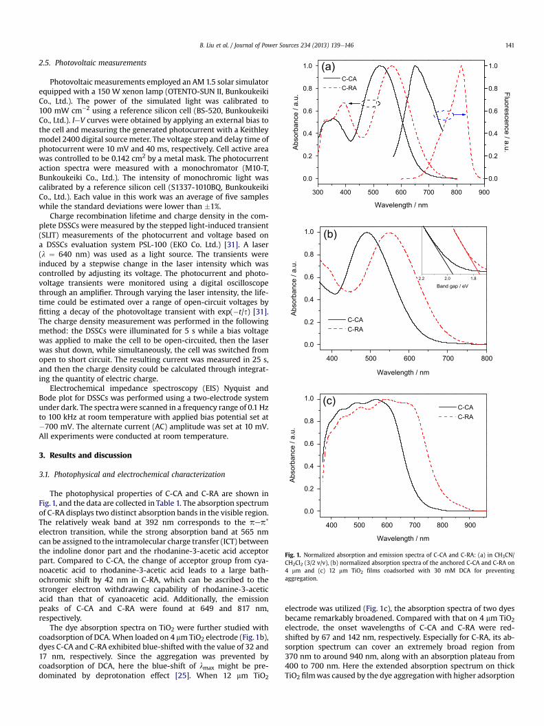
Fig. 1. Normalized absorption and emission spectra of C-CA and C-RA: (a) in CH3CN/CH2Cl2 (3/2 v/v), (b) normalized absorption spectra of the anchored C-CA and C-RA on4 mm and (c) 12 mm TiO2 films coadsorbed with 30 mM DCA for preventingaggregation.
B. Liu et al. / Journal of Power Sources 234 (2013) 139e146 141
2.5. Photovoltaic measurements
Photovoltaic measurements employed an AM 1.5 solar simulatorequipped with a 150 W xenon lamp (OTENTO-SUN II, BunkoukeikiCo., Ltd.). The power of the simulated light was calibrated to100 mW cm�2 using a reference silicon cell (BS-520, BunkoukeikiCo., Ltd.). IeV curves were obtained by applying an external bias tothe cell and measuring the generated photocurrent with a Keithleymodel 2400 digital sourcemeter. The voltage step and delay time ofphotocurrent were 10 mV and 40 ms, respectively. Cell active areawas controlled to be 0.142 cm2 by a metal mask. The photocurrentaction spectra were measured with a monochromator (M10-T,Bunkoukeiki Co., Ltd.). The intensity of monochromic light wascalibrated by a reference silicon cell (S1337-1010BQ, BunkoukeikiCo., Ltd.). Each value in this work was an average of five sampleswhile the standard deviations were lower than �1%.
Charge recombination lifetime and charge density in the com-plete DSSCs were measured by the stepped light-induced transient(SLIT) measurements of the photocurrent and voltage based ona DSSCs evaluation system PSL-100 (EKO Co. Ltd.) [31]. A laser(l ¼ 640 nm) was used as a light source. The transients wereinduced by a stepwise change in the laser intensity which wascontrolled by adjusting its voltage. The photocurrent and photo-voltage transients were monitored using a digital oscilloscopethrough an amplifier. Through varying the laser intensity, the life-time could be estimated over a range of open-circuit voltages byfitting a decay of the photovoltage transient with exp(�t/s) [31].The charge density measurement was performed in the followingmethod: the DSSCs were illuminated for 5 s while a bias voltagewas applied to make the cell to be open-circuited, then the laserwas shut down, while simultaneously, the cell was switched fromopen to short circuit. The resulting current was measured in 25 s,and then the charge density could be calculated through integrat-ing the quantity of electric charge.
Electrochemical impedance spectroscopy (EIS) Nyquist andBode plot for DSSCs was performed using a two-electrode systemunder dark. The spectrawere scanned in a frequency range of 0.1 Hzto 100 kHz at room temperature with applied bias potential set at�700 mV. The alternate current (AC) amplitude was set at 10 mV.All experiments were conducted at room temperature.
3. Results and discussion
3.1. Photophysical and electrochemical characterization
The photophysical properties of C-CA and C-RA are shown inFig. 1, and the data are collected in Table 1. The absorption spectrumof C-RA displays two distinct absorption bands in the visible region.The relatively weak band at 392 nm corresponds to the pep*
electron transition, while the strong absorption band at 565 nmcan be assigned to the intramolecular charge transfer (ICT) betweenthe indoline donor part and the rhodanine-3-acetic acid acceptorpart. Compared to C-CA, the change of acceptor group from cya-noacetic acid to rhodanine-3-acetic acid leads to a large bath-ochromic shift by 42 nm in C-RA, which can be ascribed to thestronger electron withdrawing capability of rhodanine-3-aceticacid than that of cyanoacetic acid. Additionally, the emissionpeaks of C-CA and C-RA were found at 649 and 817 nm,respectively.
The dye absorption spectra on TiO2 were further studied withcoadsorption of DCA. When loaded on 4 mmTiO2 electrode (Fig. 1b),dyes C-CA and C-RA exhibited blue-shifted with the value of 32 and17 nm, respectively. Since the aggregation was prevented bycoadsorption of DCA, here the blue-shift of lmax might be pre-dominated by deprotonation effect [25]. When 12 mm TiO2
electrode was utilized (Fig. 1c), the absorption spectra of two dyesbecame remarkably broadened. Compared with that on 4 mm TiO2electrode, the onset wavelengths of C-CA and C-RA were red-shifted by 67 and 142 nm, respectively. Especially for C-RA, its ab-sorption spectrum can cover an extremely broad region from370 nm to around 940 nm, along with an absorption plateau from400 to 700 nm. Here the extended absorption spectrum on thickTiO2 filmwas caused by the dye aggregationwith higher adsorption

300 400 500 600 700 800 9000
20
40
60
80 C-CA C-RA
IPC
E / %
Wavelength / nm
(a)
15
20 C-CA C-RA
(b)
Table 1Absorption and emission properties of C-CA and C-RA.
laba/nm 3
a/M�1 cm�1 lema/nm Stokes shiftb/nm lab
c/nm lonsetd/nm
C-CA 523 27,900 649 126 491 850C-RA 565 18,000 817 252 548 925
a Absorption peaks (lab), molar extinction coefficient ( 3), and emission peaks (lem)were measured in CH3CN/CH2Cl2 (3/2 in v/v).
b Stokes shifts were calculated from lab and lem.c lab of the dyes were evaluated on 4 mm TiO2 electrodes coadsorbed with 30 mM
DCA for preventing aggregation.d The onset wavelength (lonset) of the dyes was obtained on 12 mm TiO2
electrodes.
B. Liu et al. / Journal of Power Sources 234 (2013) 139e146142
amount. Generally, H-aggregation makes absorption spectrumblue-shift while J-aggregationmakes it red-shift. In the case of C-CAand C-RA, although the predominated dye aggregation could bebroken on 4 mmTiO2 filmwith coadsorption of 30mMDCA (Fig.1b),there was still some aggregation when adsorbed onto thicker TiO2film (12 mm; Fig. 1c). That is, even the existing of the DCA (30 mM),the J-aggregation can take place on the surface of thicker TiO2 film,which is consistent with previous reports [25,32]. The resultingbroad absorption of C-RA is preferably overlapped with solar lightspectrum, which is highly beneficial to harvest solar light, even inpart of NIR region.
However, the broad absorption spectrum also brings us anotherproblem: the narrow band gap between HOMO and LUMO levels.As shown in Table 2, the band gap (E0-0) of C-RA is only 1.75 V. Thenarrow band gap can lead the LUMO level more positive, whichmay have effect on the photo-excited electron injection efficiency.Thus, cyclic voltammograms were performed to evaluate the pos-sibility of electron injection from the excited dye molecules to theconduction band (CB) of TiO2. C-CA and C-RA show similar HOMOlevels as 0.83 and 0.88 V vs NHE, respectively. Due to the narrow E0-0, the LUMO level of C-RA is�0.87 V vsNHE, more positive than thatof C-CA (�1.11 V). As well known, the CB energy level of TiO2 (ECB) isabout �0.5 V vs NHE. According to the previous study, a minimaldriving force of 0.2 V is sufficient to ensure photo-induced electroninjection into the CB of TiO2 and regeneration of the oxidized dye[33]. Thus, the photo-induced electron injection of both dyes isguaranteed to be efficient in view of thermodynamics.
3.2. Photovoltaic performances
Previously, Uchida et al. have directly attached the acceptor ofrhodanine-3-acetic acid with an indoline donor to develop thewell-known typical DonoreAcceptor (DeA) featured dyes, such asD102, D149 and D205 [11,17,19]. Impressively, DSSCs based on dyeD205 even realized one of records in high power conversion effi-ciency (9.52%). Once, rhodanine-3-acetic acid was considered as“amazing” acceptor for developing metal-free organic sensitizers.Generally, for increasing the light-harvesting and photostability ofdyes, the aromatic rings, such as phenyl, fluorenyl, thiophene or
Table 2Electrochemical properties of dyes C-CA and C-RA.
Experimentala (V) Calculatedc (V)
HOMO E0-0b LUMO HOMO E0-0 LUMO
C-CA 0.83 1.94 �1.11 0.41 2.36 �1.95C-RA 0.88 1.75 �0.87 0.44 2.26 �1.82
a Electrochemical properties were measured in CH3CN using a dye-sensitizedTiO2 electrode as working electrode.
b E0-0 values were estimated from the intersection of tangent line and horizontalaxis in normalized absorption spectra as shown in Fig. 1b (inset).
c Calculated at the B3LYP/6e31G* level in vacuum. Note: the calculated energieswere overestimated partially due to the neglect of solvation effect.
oligothiophene segments, are preferable to be utilized [8].Strangely, when incorporation of rhodanine dye (rhodanine-3-acetic acid) as acceptor into D-p-A configuration with aromaticp-conjugation bridge, the DSSCs based on C-RA exhibited veryunexpected low efficiency. Fig. 2 shows the photovoltaic perfor-mance of C-CA and C-RA coadsorbed with 30 mM DCA, with IPCEaction spectra and IeV curves. Disappointedly, although the pho-toresponsive area of C-RA was extended to about 940 nm, the IPCEvalues were extremely low. Since the plateau IPCE values werearound 10%, the JSC of C-RAwas measured to be only 2.83 mA cm�2
(Table 3 and Fig. 2).Generally, the unbeneficial p-aggregation can quench the exci-
ted electrons through intermolecular electron transfer, resulting ina low JSC [4,8]. Hence, different concentrations of DCA as thecoadsorbent were applied to inhibit the intermolecular electrontransfer process. With increasing the concentration of DCA from30 to 120 mM, the JSC values were decreased from 2.83 to1.88 mA cm�2, which might be ascribed to the decrease of dye-loaded amount. Obviously, upon coadsorption with DCA, theintermolecular electron transfer caused by p-aggregation is not themain reason for the low IPCE value.
Firstly, we take account into the low IPCE value of C-RA, which isobviously inconsistent with its broad absorption. As known, theIPCE value is the ratio of the observed photocurrent divided by theincident photon flux (Equation (1)) [34].
IPCE ¼ LHE� Finj � hel (1)
where LHE is the light harvesting efficiency, Finj is the excitedelectron injection yield, and hel is the electron collection efficiency.Since closely related to the structural morphology of TiO2 layer,
0 100 200 300 400 500 600 7000
5
10
JSC
/ m
A cm
-2
VOC
/ mV
Fig. 2. (a) IPCE action spectra and (b) IeV curves of C-CA and C-RA sensitized DSSCswith 30 mM DCA as co-adsorbed materials.

Table 3Currentevoltage characteristics for DSSCs based on C-CA and C-RA with differentconcentrations of DCA and electrolytes.
Electrolyte DCA (mM) JSC (mA cm�2) VOC (mV) ff h (%)
C-CA A 30 18.53 649 0.71 8.49
C-RA A 30 2.83 472 0.68 0.90A 60 2.73 475 0.69 0.87A 90 2.57 471 0.69 0.83A 120 1.88 462 0.67 0.57B 30 2.92 389 0.62 0.68
B. Liu et al. / Journal of Power Sources 234 (2013) 139e146 143
here hel for two dyes should be similar due to the same preparationconditions of TiO2 electrodes. Accordingly, the possible reason forthe low IPCE value in C-RA is correlated with the low LHE or Finj.
LHE value is dependent upon the photophysical properties ofsensitizers. As shown in Fig. 3, LHE spectra of two dyes are calcu-lated from the absorption spectra of dye-loaded 12 mm TiO2 elec-trodes. C-RA shows an extremely broad light harvesting area from370 to 940 nm, including a plateau of 400e730 nmwith high value(>90%). Obviously, C-RA possesses much better LHE performancethan that of C-CA. As a consequence, the distinctly difference ofIPCE values between C-CA and C-RA can be predominately attrib-uted to the excited electron injection yield (Finj), which criticallydepends on the excited electron lifetime and redox potentials ofdyes [4].
As discussed above, the LUMO level of C-RAwas calculated to be�0.87 V, which is negative enough to ensure electron injectionfrom the excited states into the conduction band of TiO2 (ECB�0.5 V). However, the ECB will up-shift in the presence of someadditives in the electrolyte, such as tert-butylpyridine (TBP) or N-methylbenzimidazole (BMII) [35]. Thus, we removed TBP and BMIIfrom the I/I3 electrolyte, that is, using electrolyte B to fabricateDSSCs to see whether there was an obvious increase in JSC or not.The IeV data are also listed in Table 3. When the additives wereremoved from the electrolyte, the JSC value was only increased byless than 5%. Therefore, even in the presence of TBP and BMII ad-ditives in the electrolyte (electrolyte A), there is enough drivingforce for the photo-induced electron injection from the LUMO levelof C-RA to the ECB of TiO2. Therefore, considering the compatibleredox potential as well as broad LHE, the observed extremely lowIPCE and JSC for C-RA can be definitely attributed to the low electroninjection yield (Finj) with short electron lifetime.
Next, we focus on the difference in the excited electron lifetimeof dyes C-CA and C-RA. As listed in Table 1, an extraordinary large
400 500 600 700 800 900 1000
0
20
40
60
80
100 C-CA C-RA
LHE
/ %
Wavelength / nm
Fig. 3. LHE spectra of C-CA and C-RA calculated from the absorption spectra of dye-loaded 12 mm TiO2 electrodes.
Stokes shift was obtained for C-RA (252 nm), which was twice aslong as that of C-CA (126 nm). That means, upon light irradiation,the excited electrons of C-RA are easier to release energy throughthe decay process than that of C-CA, suggesting that C-RAmay haverelatively short excited electron lifetime. Generally, in DSSCs, ittakes more than a hundred picoseconds to finish the excited elec-tron injection process [36]. Accordingly, there exists a seriouscompetition between the electron injection and non-radiativedecay when the excited electron lifetime is too short (even atpicosecond level). The excited electron lifetimes of C-RA and C-CAloaded TiO2 films were measured, respectively. As expected, theexcited electron lifetime of C-RA onTiO2 filmwas only about 480 ps,almost at the same level with the electron injection process. Incontrast, the relative electron lifetime of C-CA was measured to be2.54 ns, which was 5.2 fold as that of C-RA. Obviously, comparedwith C-CA, the short excited electron lifetime in C-RA causes theserious competition between the electron injection and non-radiative decay, leading to low electron injection efficiency.
3.3. DFT simulation
To get further insight into the distinct difference in the photo-voltaic performances of C-CA and C-RA, DFT calculationwas carriedout on a B3LYP/6e31 þ G(d) level for the geometry optimization[37]. As shown in Fig. 4, the HOMO orbital of C-CA is delocalizedthroughout the whole structure, and the LUMO orbital mainly lo-cates at the linker and extends through the anchoring units. Incontrast, the LUMO electrons of C-RA are isolated from the carboxylanchoring group (eCH2CO2H) due to the presence of the methylenegroup, which may suppress the electron injection efficiency fromthe excited dyes to the CB of TiO2. Therefore, the electron destiny ofLUMO for C-RA does not closely overlap with the conduction ofTiO2, potentially resulting in the predominance toward injectingelectrons closer to the TiO2 surface with low electron injection ef-ficiency (Fig. 5).
From the DFT analysis, here we consider that the methylenegroup between the rhodanine and carboxylic acid may severelydisrupt the electronic coupling of dye and TiO2, thus lowering theefficiency of photo-excited electron injection. Obviously, it seemsconflict with the high efficiency photovoltaic dyes, such as D102,D149 and D204 [11,17,19], which also contains a similar anchoringgroup as that of the C-RA. Indeed, these D-series dyes have welldemonstrated with high photovoltaic efficiency. However, thechemical structures of D102, D149, and D205 are quite differentfrom the sensitizer C-RA, with the following considerations:
(i) The different dye configuration between D-series dyes and C-RA.In D102, D149, and D205 sensitizers, the donor (indoline part)and acceptor (rhodanine part) are connected directly withoutany aromatic p-linker, that is, these D-series dyes belong totypical DeA type sensitizers. Thus, the LUMO orbital of thesesensitizers is mainly distributed on rhodanine part, affordingmuch higher possibilities for electron injection. However, C-RA belongs to a typical D-p-A feature (Scheme 1). Uponincorporation of an additional thiophene unit as conjugationbridge, the electron distribution of LUMO orbital in C-RA ismainly delocalized over both p-linker segment bridge andrhodanine framework. With respect to the counterpart C-CAcontaining cyanoacetic acid, the electron destiny on theanchoring group of CO2H is negligible in the system of C-RAcontaining rhodanine-3-acetic acid.
(ii) In the two rhodanine units combining together as the acceptor,the anchoring interaction with TiO2 might become very compli-cated. In the DeA system of D102 containing a single rhoda-nine unit, the photovoltaic efficiency is lower than D149 and

Fig. 4. Calculated frontier orbitals of compounds C-CA and C-RA (isodensity ¼ 0.020 a.u.).
400
450
500
550
600
650
700
C-CA C-RA
VO
C /
mV
(a)
B. Liu et al. / Journal of Power Sources 234 (2013) 139e146144
D205. Moreover, in chemical structures of D149 and D205, theacceptor unit contains additional rhodanine unit, that is, tworhodanine units combine together as the acceptor, which willenhance the electron-withdrawing capability of acceptor andfurther move the electron density distribution of LUMO orbitalto rhodanine-3-acetic acid unit. Specifically, in the two-rhodanine units as acceptor, the anchoring interaction withTiO2 might become very complicated, not limited to the car-boxylic group. The two carbonyl groups in the each rhodaninecan also play much role on guaranteeing the efficient electroninjection. Recently, Tian et al. have reported a nice work on themodified rhodanine acceptor [38]. In the modified acceptor of2-(1,1-dicyanomethylene)rhodanine, the formation of coordi-nate bonds between the O and N in the middle acceptor rho-danine of RD-I and RD-II tautomers and the Lewis acid sites ofthe TiO2 surface guarantee efficient electron injection from thedyes to TiO2.
Therefore, the mono- or double-rhodanine unit as acceptor issensitive to the dye configuration and the anchoring interaction.Overall, the low photo-excited electron injection yield results in thelow photovoltaic performance of C-RA, which does not conflictwith the high photovoltaic performance of D-series sensitizers.With the investigation of excited electron lifetime discussed above,
Fig. 5. Schematic electron injection process of C-CA and C-RA.
the back-electron-transfer between the photo-excited electronsand the oxidized sensitizer is prone to take place, resulting in rel-atively low electron injection efficiency with low JSC [3,4].
3.4. Charge recombination
Besides the low JSC, the VOC of C-RA was also lower than that ofC-CA by about 177 mV, and obtained as 472 mV. To further inves-tigate the internal reason for the low photovoltage, the VOC andcharge recombination lifetime as a function of charge density based
101350
Charge density / 1018 cm -3
1010.01
0.1
1
C-CA C-RA
Cha
rge
reco
mbi
natio
n lif
etm
e / s
Charge density / 1018 cm -3
(b)
Fig. 6. (a) Open-circuit voltage (VOC) and (b) charge recombination lifetime as a func-tion of charge density based on C-CA and C-RA-sensitized solar cells.

0 10 20 30 40 50 60
0
2
4
6
8
10
12
14(a) C-CA
C-RA
-Z'' /
Ohm
Z' / Ohm
100m 1 10 100 1k 10k 100k
0
3
6
9
12
15
18
C-CA C-RA
Thet
a / d
egre
e
Frequency / Hz
(b)
Fig. 7. EIS Nyquist (a), Bode (b) plots and equivalent circuit (c) for DSSCs based on C-CAand C-RA measured in the dark. The scatters of (a) and (b) show theoretical fits usingthe equivalent circuit.
B. Liu et al. / Journal of Power Sources 234 (2013) 139e146 145
on C-CA and C-RA sensitized DSSCs in the presence of DCA weremeasured by the SLIT measurements. Generally, the VOC is deter-mined by the difference between the quasi-Fermi level of TiO2 (EFn)and the potential of the redox couple (Eredox, I�/I3� in this work) inelectrolyte. The quasi-Fermi level is associated with both the ECBand the charge density in TiO2 (Equation (2)) [39]:
EFn ¼ ECB þ kT lnðn=NcÞ (2)
where n is the injection charge density in the TiO2 electrode and Ncis the effective density of states in the CB, and the ratio n/Nc isdetermined by the balance between electron injection and charge
Table 4Parameters obtained by fitting the impedance spectra using the equivalent circuit.a
Rhb/Ohm cm�2 CPE1c/mF cm�2 n1
d R1b/Ohm cm�2 CPE2c/mF
C-CA 15.4 293.5 0.80 7.7 283.4C-RA 17.1 31.6 0.82 3.7 240.0
a Equivalent circuit of the DSSC consisting of TiO2/dye/electrolyte and Pt/electrolyte inb Rh, R1, R2, R3 are the series resistance of Pt and TCO, charge-transfer resistance at Pt/e
respectively.c CPE1, CPE2, and CPE3 are the constant phase element for the TiO2/dye/electrolyte, Ptd n presents the degree of surface inhomogeneity.
recombination. Generally, n/Nc value becomes higher when theelectron injection is more effective, resulting in longer chargerecombination lifetime. From Equation (2), both increasing chargedensity in TiO2 and decreasing the charge recombination rate canmove EFn to be more negative and give higher VOC.
In Fig. 6a, when illuminating cell devices with the same lightintensity, the electron densities of C-CA and C-RAweremeasured tobe 20.65 � 1018 and 1.77 � 1018 cm�3, respectively. Thus, in Equa-tion (2), the n value of C-RAwas less than one tenth of that of C-CA,in consistent with the poor Finj value as discussed above in LHEanalysis. Also, two curves of DSSCs based on C-CA and C-RAexhibited the similar slope, which were almost coincided with eachother. At a given charge density in the SLIT measurements, here thealmost same VOC for the two dyes based DSSCs indicates theidentical ECB for two cases. That is, the ECB is not influenced somuchby changing the acceptor units from cyanoacetic acid to rhodanine-3-acetic acid.
Because there is no obvious change in the CB of TiO2 (ECB)sensitized with the two dyes, the significant difference in photo-voltage of DSSCs should be attributed to the different chargerecombination rate. As shown in Fig. 6b, the charge recombinationlifetime decreases with charge density, and follows a power lawrelation with the same slope, indicative of the same recombinationmechanism [26]. Obviously, the charge recombination lifetimes forDSSC based on C-CA are much longer than that of C-RA at a givencharge density.
To complement the SLIT measurements, electrochemical impe-dance spectroscopy (EIS) measurements were also conducted toinvestigate the charge recombination lifetimes directly in thesedevices. Fig. 7 shows the Nyquist and Bode plots for C-CA and C-RAsensitized DSSCs measured under dark. In the Nyquist diagram,three semicircles from left to right are visible, and represent theimpedances of the charge transfer on the Pt counter electrode (R1,smaller circles), the charge recombination at TiO2/dye/electrolyteinterface (R2, larger circles), and carrier transport within electrolyte(R3, smaller circles on the right). As listed in Table 4, two dyes showsimilar Rh and R1 values due to the same electrolyte and electrodein both materials and surface area. The charge recombinationimpedance of C-RA (R2), corresponding to the diameter of middlefrequency semicircle of Nyquist plot, was calculated to be8.9 Ohm cm�2, which was less than one third of that of C-CA(27.5 Ohm cm�2). Here a smaller R2 value means faster chargerecombination rate between the CB of TiO2 and the electrolyte,indicating that the charge recombination lifetime of C-RA is shorterthan that of C-CA.
To determine the charge recombination lifetime directly, thereaction resistance of DSSCs was analyzed by ZSimpWin using anequivalent circuit shown in Fig. 7c. The charge recombinationlifetime can be calculated through Equation (3).
se ¼ 1=ð2pf Þ (3)
where f is the peak frequency in EIS Bode plot. For C-RA, the chargerecombination lifetime was calculated to be 296 ms, which is only
cm�2 n2d R2
b/Ohm cm�2 CPE3c/mF cm�2 n3d R3
b/Ohm cm�2
0.80 27.5 51,870 0.8 3.50.79 8.9 0.1113 1.0 0.9
terface.lectrolyte, at TiO2/dye/electrolyte interface, and carrier transport within electrolyte,
/electrolyte interface, and carrier transport within electrolyte, respectively.

B. Liu et al. / Journal of Power Sources 234 (2013) 139e146146
about one thirteenth of that of C-CA (3902 ms). Therefore, the trendsof charge recombination lifetime observed from SLIT and EISmeasurements are identical. As an overall result of lower chargedensity and shorter charge recombination lifetime, C-RA presentedmuch lower VOC of 472 mV than that of C-CA (649 mV). We notethat in EIS measurements, DCA was not added as the co-adsorbedmaterial, thus the charge recombination lifetime of both dyeswere relatively short. However, it will not affect the trend discussedhere.
4. Conclusion
We developed a novel D-p-A organic dye C-RA by incorporatinga carbazole substituted indoline as donor group and rhodanine-3-acetic acid as anchoring group to enhance light-harvesting ability.By replacement of cyanoacetic acid with rhodanine-3-acetic acid,the onset wavelength of photoresponsive area for dye C-RA is red-shifted to 940 nmwith high LHE values. However, the plateau IPCEvalue of C-RA sensitized DSSCs was only around 10%, resulting in anextremely low photovoltaic performance (JSC 2.83 mA cm�2, VOC472 mV, ff 0.68, and h 0.90%). The power conversion efficiency ofDSSCs based on C-RA (0.57e0.90%) is one order of magnitude withrespect to C-CA (8.49%). With the systematic studies on LHE, SLITand EIS measurements as well as DFT analysis, our results revealthat the poor photovoltaic performance for C-RA is attributed to thefollowing possible characteristics arising from the rhodanine seg-ment: i) the relatively short excited electron lifetime and the iso-lation of LUMO orbital from anchoring group, resulting in the lowphoto-excited electron injection efficiency with low JSC; ii) anoverall result of the low injection charge density in the TiO2 elec-trode and fast charge recombination rate leading to the low VOC.The analysis of EIS Bode plot indicates that the charge recombina-tion lifetime for C-RA is about 296 ms, which is only about onethirteenth of that of C-CA (3902 ms). Moreover, the mono- ordouble-rhodanine unit as acceptor is sensitive to the dye config-uration and the anchoring interaction, which does not conflict withthe high photovoltaic performance of D-series sensitizers. Withrespect to dyes D102, D149 and D205, the low photo-excitedelectron injection yield and the fast charge recombination rate re-sults in the observed extremely low photovoltaic performance of C-RA. These findings will afford powerful strategy for future devel-opment of efficient organic sensitizers, especially for those usingrhodanine-3-acetic acid as acceptor unit in D-p-A configuration.
Acknowledgments
Thisworkwas supported by National Natural Science Foundationof China (21102034 and 21176075), the Science Foundation for theExcellent Youth Scholars of Hebei Province (Y2012017), the NatureScience Foundation of Hebei Province (B2012205001) Grant-in-Aidsfor Scientific Research (A) (23245036, YN), National 973 Program(2013CB733700), the Oriental Scholarship, the FundamentalResearch Funds for the Central Universities (WK1013002), and theOpen Funding Project of State Key Laboratory of Luminescent Ma-terials and Devices (SCUT).
References
[1] B. O’Regan, M. Grätzel, Nature 353 (1991) 737.[2] J. Roncali, Adv. Energy Mater. 1 (2011) 147.[3] J. Wiberg, T. Marinado, D.P. Hagberg, L.C. Sun, A. Hagfeldt, B. Albinsson, J. Phys.
Chem. C 113 (2009) 3881.[4] Z.J. Ning, Y. Fu, H. Tian, Energy Environ. Sci. 3 (2010) 1170.[5] J. Yoon, D.K. Kang, J. Won, J.Y. Park, Y.S. Kang, J. Power Sources 201 (2012) 395.[6] A. Mishra, M.K.R. Fischer, P. Bäuerle, Angew. Chem. Int. Ed. 48 (2009) 2474.[7] M.K.R. Fischer, S. Wenger, M.K. Wang, A. Mishra, S.M. Zakeeruddin, M. Grätzel,
P. Bäuerle, Chem. Mater. 22 (2010) 1836.[8] A. Hagfeldt, G. Boschloo, L. Sun, L. Kloo, H. Pettersson, Chem. Rev. 110 (2010)
6595.[9] J.A. Mikroyannidis, D.V. Tsagkournos, P. Balraju, G.D. Sharma, J. Power Sources
196 (2011) 4152.[10] J. Zhang, H.-B. Li, S.-L. Sun, Y. Geng, Y.Wu, Z.-M. Su, J.Mater. Chem.22 (2012) 568.[11] T. Horiuchi, H. Miura, S. Uchida, Chem. Commun. (2003) 3036.[12] T. Horiuchi, H. Miura, S. Uchida, J. Photochem. Photobiol. A 164 (2004) 29.[13] Md. K. Nazeeruddin, A. Kay, I. Rodicio, R. Humphry-Baker, E. Mueller, P. Liska,
N. Vlachopoulos, M. Grätzel, J. Am. Chem. Soc. 115 (1993) 6382.[14] J.H. Yum, I. Jung, C. Baik, J. Ko, M.K. Nazeeruddin, M. Grätzel, Energy Environ.
Sci. 2 (2009) 100.[15] Y. Chiba, A. Islam, Y. Watanabe, R. Komiya, N. Koide, L.Y. Han, Jpn. J. Appl. Phys.
Part 2 45 (2006) L638.[16] Md. K. Nazeeruddin, P. Pechy, M. Grätzel, Chem. Commun. (1997) 1705.[17] T. Horiuchi, H. Miura, K. Sumioka, S. Uchida, J. Am. Chem. Soc. 126 (2004)
12218.[18] S. Ito, S.M. Zakeeruddin, R. Humphry-Baker, P. Liska, R. Charvet, P. Comte, Md.
K. Nazeeruddin, P. Péchy, M. Takata, H. Miura, S. Uchida, M. Grätzel, Adv.Mater. 18 (2006) 1202.
[19] S. Ito, H. Miura, S. Uchida, M. Takata, K. Sumioka, P. Liska, P. Comte, P. Péchy,M. Grätzel, Chem. Commun. (2008) 5194.
[20] M. Akhtaruzzaman, A. Islam, F. Yang, N. Asao, E. Kwon, S.P. Singh, L. Han,Y. Yamamoto, Chem. Commun. 47 (2011) 12400.
[21] S. Higashijima, H. Miura, T. Fujita, Y. Kubota, K. Funabiki, T. Yoshida,M. Matsui, Tetrahedron 67 (2011) 6289.
[22] K. Premaratne, G.R.A. Kumara, R.M.G. Rajapakse, M.L. Karunarathne,J. Photochem. Photobiol. A 229 (2012) 29.
[23] B. Liu,W.Zhu,Q.Zhang,M.Xu,Z.Ning,Y.Xie,H.Tian,Chem.Commun.(2009)1766.[24] B. Liu, W. Wu, X. Li, L. Li, S. Guo, X. Wei, W. Zhu, Q. Liu, Phys. Chem. Chem.
Phys. 13 (2011) 8985.[25] W. Zhu, Y. Wu, S. Wang, W. Li, X. Li, J. Chen, Z.-S. Wang, H. Tian, Adv. Funct.
Mater. 21 (2011) 756.[26] Y. Cui, Y. Wu, X. Lu, X. Zhang, G. Zhou, F. Miapeh, W. Zhu, Z.-S. Wang, Chem.
Mater. 23 (2011) 4394.[27] Y. Wu, X. Zhang, W. Li, Z.-S. Wang, H. Tian, W. Zhu, Adv. Energy Mater. 2
(2012) 149.[28] W. Li, Y. Wu, Q. Zhang, H. Tian, W. Zhu, ACS Appl. Mater. Interf. 4 (2012) 1822.[29] B. Liu, Q. Liu, D. You, X. Li, Y. Naruta, W. Zhu, J. Mater. Chem. 22 (2012) 13348.[30] S. Ito, T.N. Murakami, P. Comte, P. Liska, C. Grätzel, Md. K. Nazeeruddin,
M. Grätzel, Thin Solid Films 516 (2008) 4613.[31] S. Nakade, T. Kanzaki, Y. Wada, S. Yanagida, Langmuir 21 (2005) 10803.[32] A. Mishra, R.K. Behera, P.K. Behera, B.K. Mishra, G.B. Behera, Chem. Rev. 100
(2000) 1973.[33] (a) G. Boschloo, A. Hagfeldt, Acc. Chem. Res. 42 (2009) 1819;
(b) S. Wenger, P.A. Bouit, Q. Chen, J. Teuscher, D.D. Censo, R. Humphry-Baker,J.E. Moser, J.L. Delgado, N. Martín, S.M. Zakeeruddin, M. Grätzel, J. Am. Chem.Soc. 132 (2010) 5164.
[34] K. Kalyanasundaram, M. Grätzel, Coordin. Chem. Rev. 177 (1998) 347.[35] T. Stergiopoulos, P. Falaras, Adv. Energy Mater. 2 (2012) 616.[36] A. Listorti, B. O’Regan, J.R. Durrant, Chem. Mater. 23 (2011) 3381.[37] M.J. Frisch, G.W. Trucks, H.B. Schlegel, P.M.W. Gill, B.G. Johnson, M.A. Robb,
J.R. Cheeseman, T. Keith, G.A. Petersson, J.A. Montgomery, K. Raghavachari,M.A. Al-Laham, V.G. Zakrzewski, J.V. Ortiz, J.B. Foresman, J. Cioslowski,B.B. Stefanov, A. Nanayakkara, M. Challacombe, C.Y. Peng, P.Y. Ayala, W. Chen,M.W. Wong, J.L. Andres, E.S. Replogle, R. Gomperts, R.L. Martin, D.J. Fox,J.S. Binkley, D.J. Defrees, J. Baker, J.P. Stewart, M. Head-Gordon, C. Gonzalez,J.A. Pople, Gaussian 03, Revision E.01, Gaussian, Inc., Pittsburgh, PA, 2004.
[38] J.Y. Mao, N.N. He, Z.J. Ning, Q. Zhang, F.L. Guo, L. Chen, W.J. Wu, J.L. Hua,H. Tian, Angew. Chem. Int. Ed. 51 (2012) 9873.
[39] F. Fabregat-Santiago, G. Garcia-Belmonte, I. Mora-Séro, J. Bisquert, Phys.Chem. Chem. Phys. 13 (2011) 9083.