infiltration practices - at virginia tech since 1965 bmp spec no 8... · infiltration practices....
TRANSCRIPT
VA DEQ STORMWATER DESIGN SPECIFICATION NO. 8 INFILTRATION
Version 1.9, March 1, 2011 Page 1 of 24
VIRGINIA DEQ STORMWATER DESIGN SPECIFICATION No. 8
INFILTRATION PRACTICES
VERSION 1.9 March 1, 2011
SECTION 1: DESCRIPTION
Infiltration practices use temporary surface or underground storage to allow incoming stormwater runoff to exfiltrate into underlying soils. Runoff first passes through multiple pretreatment mechanisms to trap sediment and organic matter before it reaches the practice. As the stormwater penetrates the underlying soil, chemical and physical adsorption processes remove pollutants. Infiltration practices have the greatest runoff reduction capability of any stormwater practice and are suitable for use in residential and other urban areas where measured soil permeability rates exceed 1/2 inch per hour. To prevent possible groundwater contamination, infiltration should not be utilized at sites designated as stormwater hotspots.
SECTION 2: PERFORMANCE When used appropriately, infiltration has a very high runoff volume reduction capability, as shown in Table 8.1.
VA DEQ STORMWATER DESIGN SPECIFICATION NO. 8 INFILTRATION
Version 1.9, March 1, 2011 Page 2 of 24
Table 8.1. Summary of Stormwater Functions Provided by Infiltration
Stormwater Function Level 1 Design Level 2 Design Annual Runoff Volume Reduction (RR) 50% 90%
Total Phosphorus (TP) EMC Reduction1 by BMP Treatment Process
25% 25%
Total Phosphorus (TP) Mass Load Removal 63% 93%
Total Nitrogen (TN) EMC Reduction1 by BMP Treatment Process
15% 15%
Total Nitrogen (TN) Mass Load Removal 57% 92%
Channel and Flood Protection • Use the RRM spreadsheet to calculate the Curve Number (CN) adjustment; OR
• Design for extra storage (optional; as needed) on the surface or in the subsurface storage volume to accommodate larger storm volumes, and use NRCS TR-55 Runoff Equations 2 to compute the CN Adjustment.
1 Change in the event mean concentration (EMC) through the practice. The actual nutrient mass load removed is the product of the removal rate and the runoff reduction (RR) rate (see Table 1 in the Introduction to the New Virginia Stormwater Design Specifications). 2 NRCS TR-55 Runoff Equations 2-1 thru 2-5 and Figure 2-1 can be used to compute a curve number adjustment for larger storm events, based on the retention storage provided by the practice(s).
Sources: CWP and CSN (2008), and CWP (2007)
SECTION 3: DESIGN TABLE The major design goal for Infiltration is to maximize runoff volume reduction and nutrient removal. To this end, designers may choose to go with the baseline design (Level 1) or choose an enhanced design (Level 2) that maximizes nutrient and runoff reduction. To qualify for Level 2, the infiltration practice must meet all the design criteria shown in the right hand column of Table 8.2.
Table 8.2. Level 1 and Level 2 Infiltration Design Guidelines
Level 1 Design (RR:50; TP:25; TN:15) Level 2 Design (RR:90; TP:25; TN:15) Sizing: Tv = [(Rv)(A)/12] – the volume reduced by an upstream BMP
Sizing: Tv = [1.1(Rv)(A)/12] – the volume reduced by an upstream BMP
At least two forms of pre-treatment (see Table 8.6)
At least three forms of pre-treatment (see Table 8.6)
Soil infiltration rate 1/2 to 1 in./hr. (see Section 6.1 & Appendix 8-A); number of tests depends on the scale (Table 3)
Soil infiltration rates of 1.0 to 4.0 in/hr (see Section 6.1 & Appendix 8-A); number of tests depends on the scale (Table 8.3)
Minimum of 2 feet between the bottom of the infiltration practice and the seasonal high water table or bedrock (Section 4 5)
Tv infiltrates within 36 to 48 hours (Section 6.6) Building Setbacks – see Table 8.3
All Designs are subject to hotspot runoff restrictions/prohibitions
VA DEQ STORMWATER DESIGN SPECIFICATION NO. 8 INFILTRATION
Version 1.9, March 1, 2011 Page 3 of 24
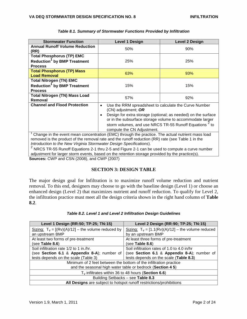
SECTION 4: TYPICAL DETAILS
Figure 8.1. Infiltration Plan and Section
VA DEQ STORMWATER DESIGN SPECIFICATION NO. 8 INFILTRATION
Version 1.9, March 1, 2011 Page 4 of 24
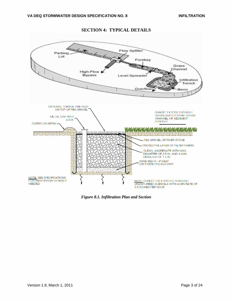
Figure 8.2A: Infiltration Section with Supplemental Pipe Storage
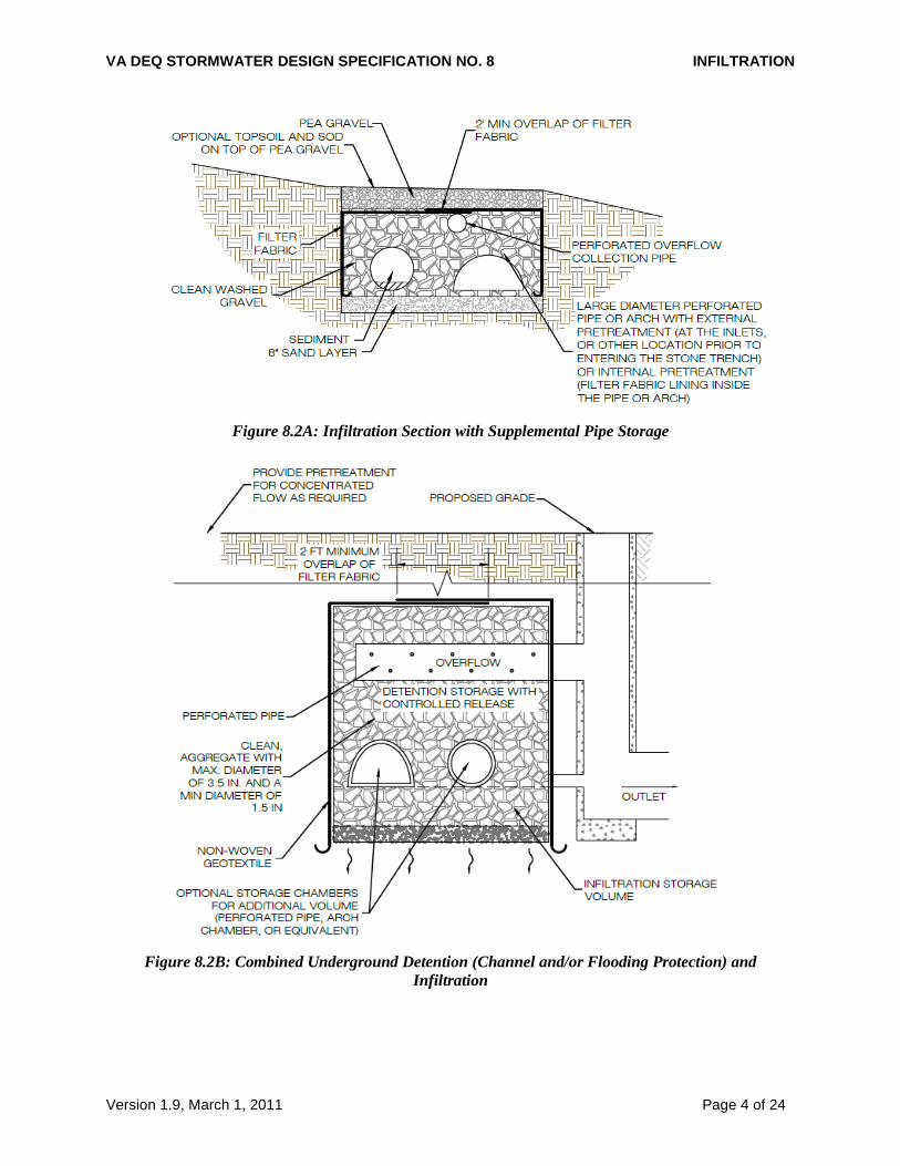
Figure 8.2B: Combined Underground Detention (Channel and/or Flooding Protection) and
Infiltration
VA DEQ STORMWATER DESIGN SPECIFICATION NO. 8 INFILTRATION
Version 1.9, March 1, 2011 Page 5 of 24
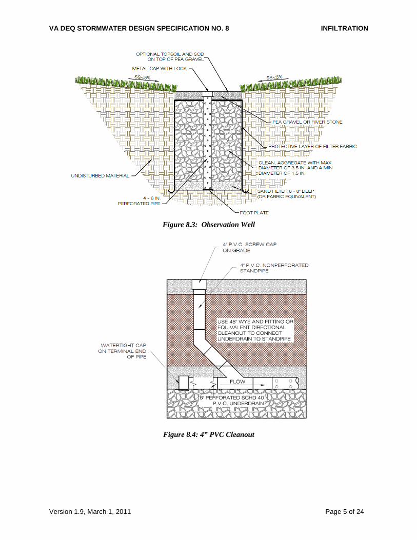
Figure 8.3: Observation Well
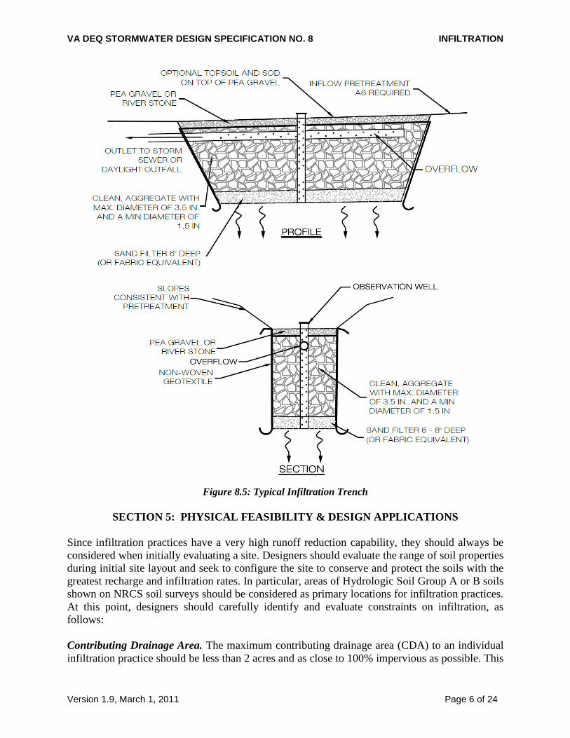
Figure 8.4: 4” PVC Cleanout
VA DEQ STORMWATER DESIGN SPECIFICATION NO. 8 INFILTRATION
Version 1.9, March 1, 2011 Page 6 of 24
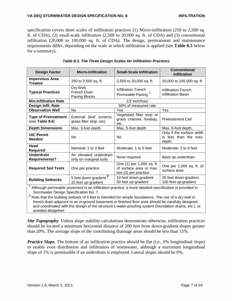
Figure 8.5: Typical Infiltration Trench
SECTION 5: PHYSICAL FEASIBILITY & DESIGN APPLICATIONS
Since infiltration practices have a very high runoff reduction capability, they should always be considered when initially evaluating a site. Designers should evaluate the range of soil properties during initial site layout and seek to configure the site to conserve and protect the soils with the greatest recharge and infiltration rates. In particular, areas of Hydrologic Soil Group A or B soils shown on NRCS soil surveys should be considered as primary locations for infiltration practices. At this point, designers should carefully identify and evaluate constraints on infiltration, as follows: Contributing Drainage Area. The maximum contributing drainage area (CDA) to an individual infiltration practice should be less than 2 acres and as close to 100% impervious as possible. This
VA DEQ STORMWATER DESIGN SPECIFICATION NO. 8 INFILTRATION
Version 1.9, March 1, 2011 Page 7 of 24
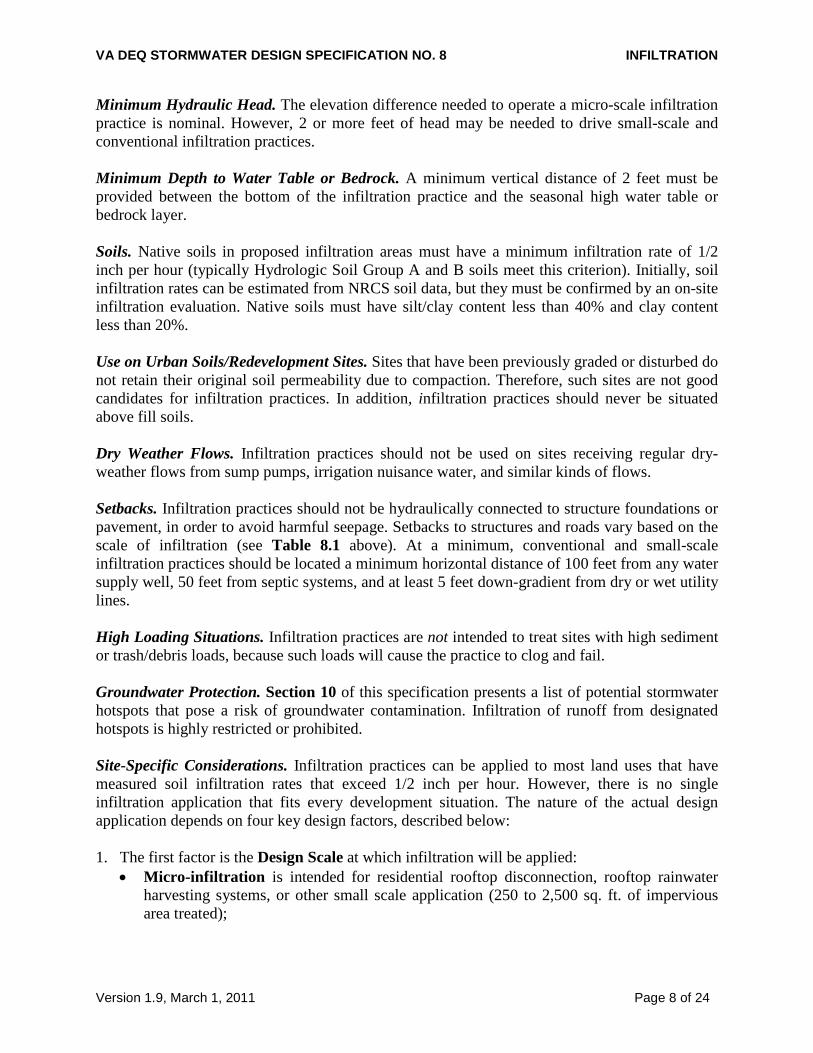
specification covers three scales of infiltration practices (1) Micro-infiltration (250 to 2,500 sq. ft. of CDA), (2) small-scale infiltration (2,500 to 20,000 sq. ft. of CDA) and (3) conventional infiltration (20,000 to 100,000 sq. ft. of CDA). The design, pretreatment and maintenance requirements differ, depending on the scale at which infiltration is applied (see Table 8.3 below for a summary).
Table 8.3. The Three Design Scales for Infiltration Practices
Design Factor Micro-Infiltration Small-Scale Infiltration Conventional Infiltration
Impervious Area Treated 250 to 2,500 sq. ft. 2,500 to 20,000 sq. ft. 20,000 to 100,000 sq. ft.
Typical Practices Dry Well French Drain Paving Blocks
Infiltration Trench Permeable Paving 1
Infiltration Trench Infiltration Basin
Min.Infiltration Rate 1/2 inch/hour Design Infil. Rate 50% of measured rate Observation Well No Yes Yes
Type of Pretreatment (see Table 8.6)
External (leaf screens, grass filter strip, etc)
Vegetated filter strip or grass channel, forebay, etc.
Pretreatment Cell
Depth Dimensions Max. 3-foot depth Max. 5-foot depth Max. 6-foot depth,
UIC Permit Needed No No
Only if the surface width is less than the max. depth
Head Required Nominal: 1 to 3 feet Moderate: 1 to 5 feet Moderate: 2 to 6 feet
Underdrain Requirements?
An elevated underdrain only on marginal soils None required Back up underdrain
Required Soil Tests One per practice One (1) per 1,000 sq. ft. of surface area or max. two (2) per practice.
One per 1,000 sq. ft. of surface area.
Building Setbacks 5 feet down-gradient 2 25 feet up-gradient
10 feet down-gradient 50 feet up-gradient
25 feet down-gradient 100 feet up-gradient
1 Although permeable pavement is an infiltration practice, a more detailed specification is provided in Stormwater Design Specification No. 7. 2 Note that the building setback of 5 feet is intended for simple foundations. The use of a dry well or french drain adjacent to an in-ground basement or finished floor area should be carefully designed and coordinated with the design of the structure’s water-proofing system (foundation drains, etc.), or avoided altogether.
Site Topography. Unless slope stability calculations demonstrate otherwise, infiltration practices should be located a minimum horizontal distance of 200 feet from down-gradient slopes greater than 20%. The average slope of the contributing drainage areas should be less than 15%. Practice Slope. The bottom of an infiltration practice should be flat (i.e., 0% longitudinal slope) to enable even distribution and infiltration of stormwater, although a maximum longitudinal slope of 1% is permissible if an underdrain is employed. Lateral slopes should be 0%.
VA DEQ STORMWATER DESIGN SPECIFICATION NO. 8 INFILTRATION
Version 1.9, March 1, 2011 Page 8 of 24
Minimum Hydraulic Head. The elevation difference needed to operate a micro-scale infiltration practice is nominal. However, 2 or more feet of head may be needed to drive small-scale and conventional infiltration practices. Minimum Depth to Water Table or Bedrock. A minimum vertical distance of 2 feet must be provided between the bottom of the infiltration practice and the seasonal high water table or bedrock layer. Soils. Native soils in proposed infiltration areas must have a minimum infiltration rate of 1/2 inch per hour (typically Hydrologic Soil Group A and B soils meet this criterion). Initially, soil infiltration rates can be estimated from NRCS soil data, but they must be confirmed by an on-site infiltration evaluation. Native soils must have silt/clay content less than 40% and clay content less than 20%. Use on Urban Soils/Redevelopment Sites. Sites that have been previously graded or disturbed do not retain their original soil permeability due to compaction. Therefore, such sites are not good candidates for infiltration practices. In addition, infiltration practices should never be situated above fill soils. Dry Weather Flows. Infiltration practices should not be used on sites receiving regular dry-weather flows from sump pumps, irrigation nuisance water, and similar kinds of flows. Setbacks. Infiltration practices should not be hydraulically connected to structure foundations or pavement, in order to avoid harmful seepage. Setbacks to structures and roads vary based on the scale of infiltration (see Table 8.1 above). At a minimum, conventional and small-scale infiltration practices should be located a minimum horizontal distance of 100 feet from any water supply well, 50 feet from septic systems, and at least 5 feet down-gradient from dry or wet utility lines. High Loading Situations. Infiltration practices are not intended to treat sites with high sediment or trash/debris loads, because such loads will cause the practice to clog and fail. Groundwater Protection. Section 10 of this specification presents a list of potential stormwater hotspots that pose a risk of groundwater contamination. Infiltration of runoff from designated hotspots is highly restricted or prohibited. Site-Specific Considerations. Infiltration practices can be applied to most land uses that have measured soil infiltration rates that exceed 1/2 inch per hour. However, there is no single infiltration application that fits every development situation. The nature of the actual design application depends on four key design factors, described below: 1. The first factor is the Design Scale at which infiltration will be applied:
• Micro-infiltration is intended for residential rooftop disconnection, rooftop rainwater harvesting systems, or other small scale application (250 to 2,500 sq. ft. of impervious area treated);
VA DEQ STORMWATER DESIGN SPECIFICATION NO. 8 INFILTRATION
Version 1.9, March 1, 2011 Page 9 of 24
• Small-scale infiltration is intended for residential and/or small commercial applications that meet the feasibility criteria noted above; and
• Conventional infiltration can be considered for most typical development and redevelopment applications and therefore has more rigorous site selection and feasibility criteria.
Table 8.3 above compares the different design approaches and requirements associated with each infiltration scale.
2. The second key design factor relates to the mode (or method) of temporarily storing runoff
prior to infiltration – either on the surface or in an underground trench. When storing runoff on the surface (e.g., an infiltration basin), the maximum depth should be no greater than 1 foot. However, if pretreatment cells are used, a maximum depth of 2 feet is permissible. In the underground mode, runoff is stored in the voids of the stones, and infiltrates into the underlying soil matrix. Perforated corrugated metal pipe, plastic pipe, concrete arch pipe, or comparable materials can be used in conjunction with the stone to increase the available temporary underground storage. In some instances, a combination of filtration and infiltration cells can be installed in the floor of a dry extended detention (ED) pond.
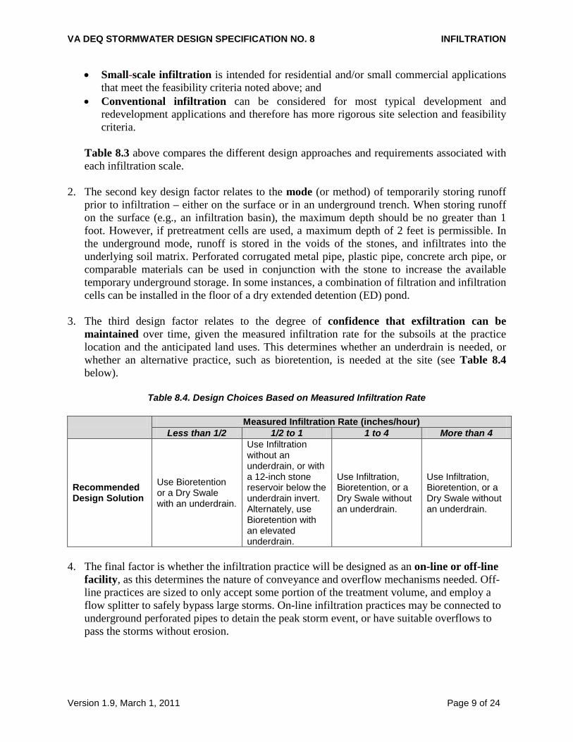
3. The third design factor relates to the degree of confidence that exfiltration can be
maintained over time, given the measured infiltration rate for the subsoils at the practice location and the anticipated land uses. This determines whether an underdrain is needed, or whether an alternative practice, such as bioretention, is needed at the site (see Table 8.4 below).
Table 8.4. Design Choices Based on Measured Infiltration Rate
Measured Infiltration Rate (inches/hour)
Less than 1/2 1/2 to 1 1 to 4 More than 4
Recommended Design Solution
Use Bioretention or a Dry Swale with an underdrain.
Use Infiltration without an underdrain, or with a 12-inch stone reservoir below the underdrain invert. Alternately, use Bioretention with an elevated underdrain.
Use Infiltration, Bioretention, or a Dry Swale without an underdrain.
Use Infiltration, Bioretention, or a Dry Swale without an underdrain.
4. The final factor is whether the infiltration practice will be designed as an on-line or off-line
facility, as this determines the nature of conveyance and overflow mechanisms needed. Off-line practices are sized to only accept some portion of the treatment volume, and employ a flow splitter to safely bypass large storms. On-line infiltration practices may be connected to underground perforated pipes to detain the peak storm event, or have suitable overflows to pass the storms without erosion.
VA DEQ STORMWATER DESIGN SPECIFICATION NO. 8 INFILTRATION
Version 1.9, March 1, 2011 Page 10 of 24
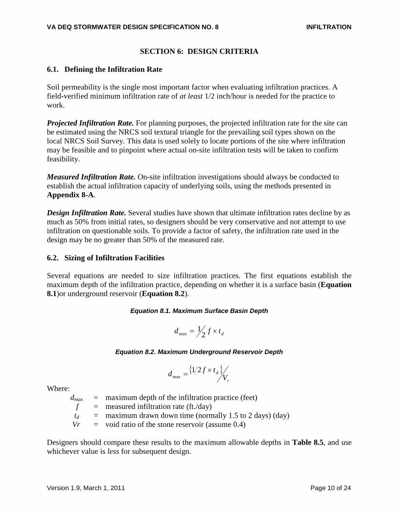
SECTION 6: DESIGN CRITERIA 6.1. Defining the Infiltration Rate Soil permeability is the single most important factor when evaluating infiltration practices. A field-verified minimum infiltration rate of at least 1/2 inch/hour is needed for the practice to work. Projected Infiltration Rate. For planning purposes, the projected infiltration rate for the site can be estimated using the NRCS soil textural triangle for the prevailing soil types shown on the local NRCS Soil Survey. This data is used solely to locate portions of the site where infiltration may be feasible and to pinpoint where actual on-site infiltration tests will be taken to confirm feasibility. Measured Infiltration Rate. On-site infiltration investigations should always be conducted to establish the actual infiltration capacity of underlying soils, using the methods presented in Appendix 8-A. Design Infiltration Rate. Several studies have shown that ultimate infiltration rates decline by as much as 50% from initial rates, so designers should be very conservative and not attempt to use infiltration on questionable soils. To provide a factor of safety, the infiltration rate used in the design may be no greater than 50% of the measured rate. 6.2. Sizing of Infiltration Facilities Several equations are needed to size infiltration practices. The first equations establish the maximum depth of the infiltration practice, depending on whether it is a surface basin (Equation 8.1)or underground reservoir (Equation 8.2).
Equation 8.1. Maximum Surface Basin Depth
dtfd ×= 21
max
Equation 8.2. Maximum Underground Reservoir Depth
{ }
r
dV
tfd ×= 21max
Where: dmax = maximum depth of the infiltration practice (feet) f = measured infiltration rate (ft./day) td = maximum drawn down time (normally 1.5 to 2 days) (day) Vr = void ratio of the stone reservoir (assume 0.4)
Designers should compare these results to the maximum allowable depths in Table 8.5, and use whichever value is less for subsequent design.
VA DEQ STORMWATER DESIGN SPECIFICATION NO. 8 INFILTRATION
Version 1.9, March 1, 2011 Page 11 of 24
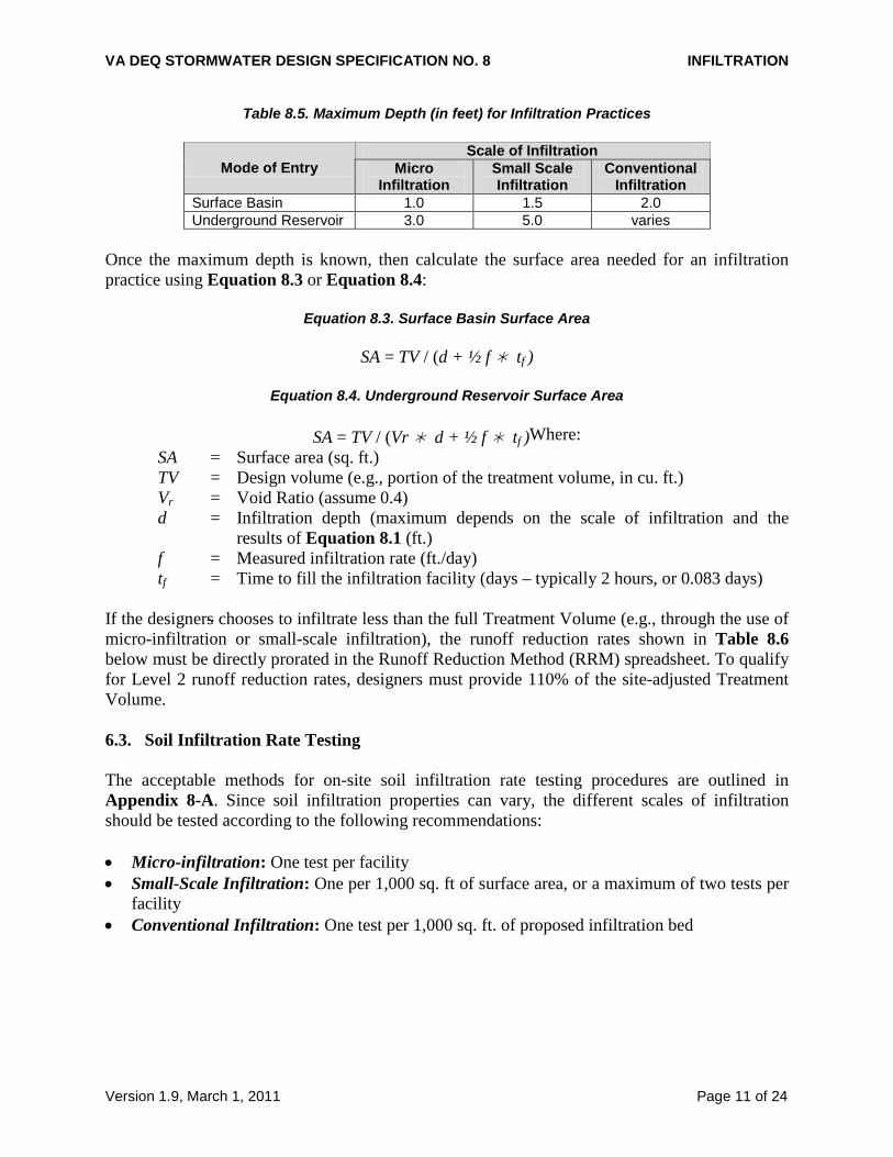
Table 8.5. Maximum Depth (in feet) for Infiltration Practices
Mode of Entry Scale of Infiltration
Micro Infiltration
Small Scale Infiltration
Conventional Infiltration
Surface Basin 1.0 1.5 2.0 Underground Reservoir 3.0 5.0 varies
Once the maximum depth is known, then calculate the surface area needed for an infiltration practice using Equation 8.3 or Equation 8.4:
Equation 8.3. Surface Basin Surface Area
SA = TV / (d + ½ f tf )
Equation 8.4. Underground Reservoir Surface Area
SA = TV / (Vr d + ½ f tf )Where: SA = Surface area (sq. ft.) TV = Design volume (e.g., portion of the treatment volume, in cu. ft.) Vr = Void Ratio (assume 0.4) d = Infiltration depth (maximum depends on the scale of infiltration and the
results of Equation 8.1 (ft.) f = Measured infiltration rate (ft./day) tf = Time to fill the infiltration facility (days – typically 2 hours, or 0.083 days)
If the designers chooses to infiltrate less than the full Treatment Volume (e.g., through the use of micro-infiltration or small-scale infiltration), the runoff reduction rates shown in Table 8.6 below must be directly prorated in the Runoff Reduction Method (RRM) spreadsheet. To qualify for Level 2 runoff reduction rates, designers must provide 110% of the site-adjusted Treatment Volume. 6.3. Soil Infiltration Rate Testing The acceptable methods for on-site soil infiltration rate testing procedures are outlined in Appendix 8-A. Since soil infiltration properties can vary, the different scales of infiltration should be tested according to the following recommendations: • Micro-infiltration: One test per facility • Small-Scale Infiltration: One per 1,000 sq. ft of surface area, or a maximum of two tests per
facility • Conventional Infiltration: One test per 1,000 sq. ft. of proposed infiltration bed
VA DEQ STORMWATER DESIGN SPECIFICATION NO. 8 INFILTRATION
Version 1.9, March 1, 2011 Page 12 of 24
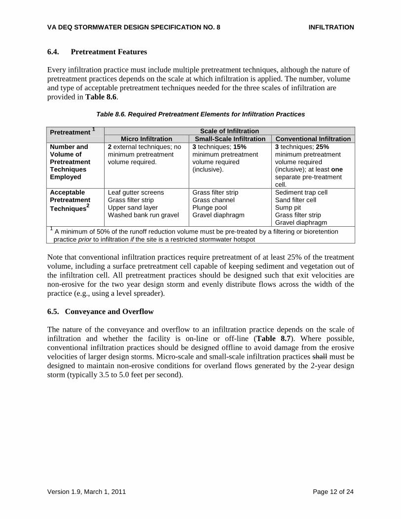
6.4. Pretreatment Features Every infiltration practice must include multiple pretreatment techniques, although the nature of pretreatment practices depends on the scale at which infiltration is applied. The number, volume and type of acceptable pretreatment techniques needed for the three scales of infiltration are provided in Table 8.6.
Table 8.6. Required Pretreatment Elements for Infiltration Practices Pretreatment 1 Scale of Infiltration
Micro Infiltration Small-Scale Infiltration Conventional Infiltration Number and Volume of Pretreatment Techniques Employed
2 external techniques; no minimum pretreatment volume required.
3 techniques; 15% minimum pretreatment volume required (inclusive).
3 techniques; 25% minimum pretreatment volume required (inclusive); at least one separate pre-treatment cell.
Acceptable Pretreatment Techniques2
Leaf gutter screens Grass filter strip Upper sand layer Washed bank run gravel
Grass filter strip Grass channel Plunge pool Gravel diaphragm
Sediment trap cell Sand filter cell Sump pit Grass filter strip Gravel diaphragm
1 A minimum of 50% of the runoff reduction volume must be pre-treated by a filtering or bioretention practice prior to infiltration if the site is a restricted stormwater hotspot
Note that conventional infiltration practices require pretreatment of at least 25% of the treatment volume, including a surface pretreatment cell capable of keeping sediment and vegetation out of the infiltration cell. All pretreatment practices should be designed such that exit velocities are non-erosive for the two year design storm and evenly distribute flows across the width of the practice (e.g., using a level spreader). 6.5. Conveyance and Overflow The nature of the conveyance and overflow to an infiltration practice depends on the scale of infiltration and whether the facility is on-line or off-line (Table 8.7). Where possible, conventional infiltration practices should be designed offline to avoid damage from the erosive velocities of larger design storms. Micro-scale and small-scale infiltration practices shall must be designed to maintain non-erosive conditions for overland flows generated by the 2-year design storm (typically 3.5 to 5.0 feet per second).
VA DEQ STORMWATER DESIGN SPECIFICATION NO. 8 INFILTRATION
Version 1.9, March 1, 2011 Page 13 of 24
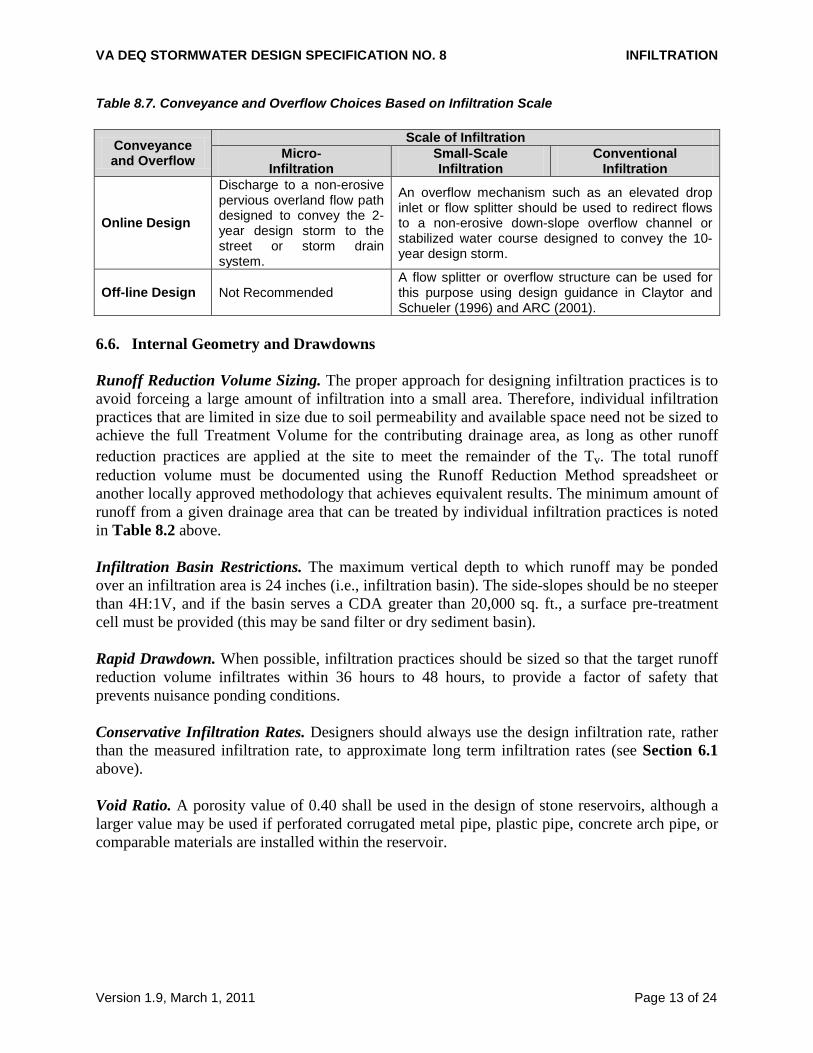
Table 8.7. Conveyance and Overflow Choices Based on Infiltration Scale
Conveyance and Overflow
Scale of Infiltration Micro-
Infiltration Small-Scale Infiltration
Conventional Infiltration
Online Design
Discharge to a non-erosive pervious overland flow path designed to convey the 2-year design storm to the street or storm drain system.
An overflow mechanism such as an elevated drop inlet or flow splitter should be used to redirect flows to a non-erosive down-slope overflow channel or stabilized water course designed to convey the 10-year design storm.
Off-line Design Not Recommended A flow splitter or overflow structure can be used for this purpose using design guidance in Claytor and Schueler (1996) and ARC (2001).
6.6. Internal Geometry and Drawdowns Runoff Reduction Volume Sizing. The proper approach for designing infiltration practices is to avoid forceing a large amount of infiltration into a small area. Therefore, individual infiltration practices that are limited in size due to soil permeability and available space need not be sized to achieve the full Treatment Volume for the contributing drainage area, as long as other runoff reduction practices are applied at the site to meet the remainder of the Tv. The total runoff reduction volume must be documented using the Runoff Reduction Method spreadsheet or another locally approved methodology that achieves equivalent results. The minimum amount of runoff from a given drainage area that can be treated by individual infiltration practices is noted in Table 8.2 above. Infiltration Basin Restrictions. The maximum vertical depth to which runoff may be ponded over an infiltration area is 24 inches (i.e., infiltration basin). The side-slopes should be no steeper than 4H:1V, and if the basin serves a CDA greater than 20,000 sq. ft., a surface pre-treatment cell must be provided (this may be sand filter or dry sediment basin). Rapid Drawdown. When possible, infiltration practices should be sized so that the target runoff reduction volume infiltrates within 36 hours to 48 hours, to provide a factor of safety that prevents nuisance ponding conditions. Conservative Infiltration Rates. Designers should always use the design infiltration rate, rather than the measured infiltration rate, to approximate long term infiltration rates (see Section 6.1 above). Void Ratio. A porosity value of 0.40 shall be used in the design of stone reservoirs, although a larger value may be used if perforated corrugated metal pipe, plastic pipe, concrete arch pipe, or comparable materials are installed within the reservoir.
VA DEQ STORMWATER DESIGN SPECIFICATION NO. 8 INFILTRATION
Version 1.9, March 1, 2011 Page 14 of 24
6.7. Landscaping and Safety Infiltration trenches can be effectively integrated into the site plan and aesthetically designed with adjacent native landscaping or turf cover, subject to the following additional design considerations: • Infiltration practices should NEVER be installed until all up-gradient construction is
completed AND pervious areas are stabilized with dense and healthy vegetation. • Vegetation associated with the infiltration practice buffers should be regularly mowed and
maintained to keep organic matter out of the infiltration device and maintain enough native vegetation to prevent soil erosion from occurring.
• Infiltration practices do not pose any major safety hazards after construction. However, if an infiltration practice will be excavated to a depth greater than 5 feet, OSHA health and safety guidelines shall be followed for safe construction practices.
• Fencing of infiltration trenches is neither necessary nor desirable. Designers should always evaluate the nature of future operations to determine if the proposed site will be designated as a potential stormwater hotspot (see Section 10.1), and comply with the appropriate restrictions or prohibitions applicable to infiltration. 6.8. Maintenance Reduction Features Maintenance is a crucial element that ensures the long-term performance of infiltration practices. The most frequently cited maintenance problem for infiltration practices is clogging of the stone by organic matter and sediment. The following design features can minimize the risk of clogging: Observation Well. Small-scale and conventional infiltration practices should include an observation well, consisting of an anchored 6-inch diameter perforated PVC pipe fitted with a lockable cap installed flush with the ground surface, to facilitate periodic inspection and maintenance. No Filter Fabric on Bottom. Avoid installing geotextile filter fabric along the bottom of infiltration practices. Experience has shown that filter fabric is prone to clogging, and a layer of coarse washed stone (choker stone) is a more effective substitute. However, permeable filter fabric must be installed on the trench sides to prevent soil piping. Direct Maintenance Access. Access must be provided to allow personnel and heavy equipment to perform non-routine maintenance tasks, such as practice reconstruction or rehabilitation. While a turf cover is permissible for micro- and small-scale infiltration practices, the surface must never be covered by an impermeable material, such as asphalt or concrete. 6.9. Infiltration Material Specifications The basic material specifications for infiltration practices are outlined in Table 8.8 below.
VA DEQ STORMWATER DESIGN SPECIFICATION NO. 8 INFILTRATION
Version 1.9, March 1, 2011 Page 15 of 24
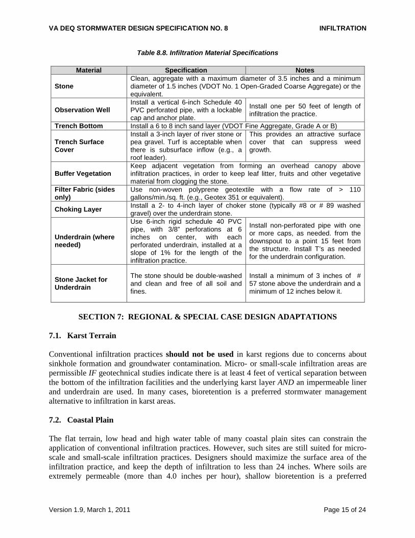
Table 8.8. Infiltration Material Specifications
Material Specification Notes
Stone Clean, aggregate with a maximum diameter of 3.5 inches and a minimum diameter of 1.5 inches (VDOT No. 1 Open-Graded Coarse Aggregate) or the equivalent.
Observation Well Install a vertical 6-inch Schedule 40 PVC perforated pipe, with a lockable cap and anchor plate.
Install one per 50 feet of length of infiltration the practice.
Trench Bottom Install a 6 to 8 inch sand layer (VDOT Fine Aggregate, Grade A or B)
Trench Surface Cover
Install a 3-inch layer of river stone or pea gravel. Turf is acceptable when there is subsurface inflow (e.g., a roof leader).
This provides an attractive surface cover that can suppress weed growth.
Buffer Vegetation Keep adjacent vegetation from forming an overhead canopy above infiltration practices, in order to keep leaf litter, fruits and other vegetative material from clogging the stone.
Filter Fabric (sides only)
Use non-woven polyprene geotextile with a flow rate of > 110 gallons/min./sq. ft. (e.g., Geotex 351 or equivalent).
Choking Layer Install a 2- to 4-inch layer of choker stone (typically #8 or # 89 washed gravel) over the underdrain stone.
Underdrain (where needed)
Use 6-inch rigid schedule 40 PVC pipe, with 3/8” perforations at 6 inches on center, with each perforated underdrain, installed at a slope of 1% for the length of the infiltration practice.
Install non-perforated pipe with one or more caps, as needed. from the downspout to a point 15 feet from the structure. Install T’s as needed for the underdrain configuration.
Stone Jacket for Underdrain
The stone should be double-washed and clean and free of all soil and fines.
Install a minimum of 3 inches of # 57 stone above the underdrain and a minimum of 12 inches below it.
SECTION 7: REGIONAL & SPECIAL CASE DESIGN ADAPTATIONS
7.1. Karst Terrain Conventional infiltration practices should not be used in karst regions due to concerns about sinkhole formation and groundwater contamination. Micro- or small-scale infiltration areas are permissible IF geotechnical studies indicate there is at least 4 feet of vertical separation between the bottom of the infiltration facilities and the underlying karst layer AND an impermeable liner and underdrain are used. In many cases, bioretention is a preferred stormwater management alternative to infiltration in karst areas. 7.2. Coastal Plain The flat terrain, low head and high water table of many coastal plain sites can constrain the application of conventional infiltration practices. However, such sites are still suited for micro-scale and small-scale infiltration practices. Designers should maximize the surface area of the infiltration practice, and keep the depth of infiltration to less than 24 inches. Where soils are extremely permeable (more than 4.0 inches per hour), shallow bioretention is a preferred
VA DEQ STORMWATER DESIGN SPECIFICATION NO. 8 INFILTRATION
Version 1.9, March 1, 2011 Page 16 of 24
alternative. Where soils are more impermeable (i.e., marine clays with less than 0.5 inches per hour), designers may prefer to use a constructed wetland practice. 7.3. Steep Terrain Forcing conventional infiltration practices in steep terrain can be problematic with respect to slope stability, excessive hydraulic gradients and sediment delivery. Unless slope stability calculations demonstrate otherwise, it is generally recommended that infiltration practices should be located a minimum horizontal distance of 200 feet from down-gradient slopes greater than 20%. Micro-scale and small-scale infiltration can work well, as long as their smaller up-gradient and down-gradient building setbacks are satisfied. 7.4. Cold Climate and Winter Performance Infiltration practices can be designed to withstand more moderate winter conditions. The main problem is caused by ice forming in the voids or the subsoils below the practice, which may briefly result in nuisance flooding when spring melting occurs. The following design adjustments are recommended for infiltration practices installed in higher elevations: • The bottom of the practice should extend below the frost line. • Infiltration practices are not recommended at roadside locations that are heavily sanded
and/or salted in the winter months (to prevent movement of chlorides into groundwater and prevent clogging by road sand).
• Pre-treatment measures can be oversized to account for the additional sediment load caused by road sanding (up to 40% of the Treatment Volume).
• Infiltration practices must be set back at least 25 feet from roadways to prevent potential frost heaving of the road pavement.
7.5. Linear Highway Sites Infiltration practices can work well for linear highway projects, where soils are suitable and can be protected from heavy disturbance and compaction during road construction operations.
SECTION 8: CONSTRUCTION 8.1. Construction Sequence The following is a typical construction sequence to properly install infiltration practices. The sequence may need to be modified to reflect the scale of infiltration, site conditions, and whether or not an underdrain needs to be installed. Infiltration practices are particularly vulnerable to failure during the construction phase for two reasons. First, if the construction sequence is not followed correctly, construction sediment can clog the practice. In addition, heavy construction can result in compaction of the soil, which can then reduce the soil’s infiltration rate. For this reason, a careful construction sequence needs to be followed.
VA DEQ STORMWATER DESIGN SPECIFICATION NO. 8 INFILTRATION
Version 1.9, March 1, 2011 Page 17 of 24
During site construction, the following steps are absolutely critical: • Avoid excessive compaction by preventing construction equipment and vehicles from
traveling over the proposed location of the infiltration practice. • Keep the infiltration practice “off-line” until construction is complete. Prevent sediment from
entering the infiltration site by using super silt fence, diversion berms or other means. In the erosion and sediment (E&S) control plan, indicate the earliest time at which stormwater runoff may be directed to a conventional infiltration basin The E&S control plan must also indicate the specific methods to be used to temporarily keep runoff from the infiltration site.
• Infiltration practice sites should never serve as the sites for temporary sediment control devices (e.g., sediment traps, etc.) during construction.
• Upland drainage areas need to be completely stabilized with a thick layer of vegetation prior to commencing excavation for an infiltration practice, as verified by the local erosion and sediment control inspector/program.
The actual installation of an infiltration practice is done using the following steps: 1. Excavate the infiltration practice to the design dimensions from the side, using a backhoe or
excavator. The floor of the pit should be completely level, but equipment should be kept off the floor area to prevent soil compaction.
2. Correctly install filter fabric on the trench sides. Large tree roots should be trimmed flush
with the sides of infiltration trenches to prevent puncturing or tearing of the filter fabric during subsequent installation procedures. When laying out the geotextile, the width should include sufficient material to compensate for perimeter irregularities in the trench and for a 6-inch minimum overlap at the top of the trench. The filter fabric itself should be tucked under the sand layer on the bottom of the infiltration trench. Stones or other anchoring objects should be placed on the fabric at the trench sides, to keep the trench open during windy periods. Voids may occur between the fabric and the excavated sides of a trench. Natural soils should be placed in all voids, to ensure the fabric conforms smoothly to the sides of excavation.
3. Scarify the bottom of the infiltration practice, and spread 6 inches of sand on the bottom as a
filter layer. 4. Install the underdrain, if one is needed. 5. Anchor the observation well(s), and add stone to the practice in 1-foot lifts. 6. Use sod to establish a dense turf cover for at least 10 feet on each side of the infiltration
practice, to reduce erosion and sloughing. If the vegetation is seeded instead, use native grasses primarily due to their adaptability to local climates and soil conditions.
VA DEQ STORMWATER DESIGN SPECIFICATION NO. 8 INFILTRATION
Version 1.9, March 1, 2011 Page 18 of 24
8.2. Construction Inspection Inspections are needed during construction to ensure that the infiltration practice is built in accordance with the approved design and this specification. Qualified individuals should use detailed inspection checklists to include sign-offs at critical stages of construction, to ensure that the contractor’s interpretation of the plan is consistent with the designer’s intentions. An example construction phase inspection checklist for Infiltration practices can be accessed at the CWP website at:
http://www.cwp.org/Resource_Library/Controlling_Runoff_and_Discharges/sm.htm (scroll to Tool6: Plan Review, BMP Construction, and Maintenance Checklists)
SECTION 9: MAINTENANCE
9.1. Maintenance Agreements Section 4 VAC 50-60-124 of the regulations specifies the circumstances under which a maintenance agreement must be executed between the owner and the local program. This section sets forth inspection requirements, compliance procedures if maintenance is neglected, notification of the local program upon transfer of ownership, and right-of-entry for local program personnel. When micro-scale or small-scale infiltration practices are installed on private residential lots, homeowners will need to (1) be educated about their routine maintenance needs, (2) understand the long-term maintenance plan, and (3) be subject to a deed restriction, drainage easement or other mechanism enforceable by the qualifying local program to ensure that infiltrating areas are not converted or disturbed. The mechanism should, if possible, grant authority for local agencies to access the property for inspection or corrective action. In addition, the GPS coordinates should be logged for all infiltration practices, upon facility acceptance, and submitted for entry into the local BMP maintenance tracking database. 9.2. Maintenance Inspections Annual site inspections are critical to the performance and longevity of infiltration practices, particularly for small-scale and conventional infiltration practices. Maintenance of infiltration practices is driven by annual inspections that evaluate the condition and performance of the practices, including the following: • The drawdown rate should be measured at the observation well for three days following a
storm event in excess of 1/2 inch in depth. If standing water is still observed in the well after three days, this is a clear sign that that clogging is a problem.
• Check inlets, pre-treatment cells, and any flow diversion structures for sediment buildup and structural damage. Note if any sediment needs to be removed.
• Inspect the condition of the observation well and make sure it is still capped. • Check that no vegetation forms an overhead canopy that may drop leaf litter, fruits and other
vegetative materials that could clog the infiltration device.
VA DEQ STORMWATER DESIGN SPECIFICATION NO. 8 INFILTRATION
Version 1.9, March 1, 2011 Page 19 of 24
• Evaluate the vegetative quality of the adjacent grass buffer and peform spot-reseeding if the cover density is less than 90%.
• Generally inspect the upland CDA for any controllable sources of sediment or erosion. • Look for weedy growth on the stone surface that might indicate sediment deposition or
clogging. • Inspect maintenance access to ensure it is free of woody vegetation, and check to see whether
valves, manholes and/or locks can be opened and operated. • Inspect internal and external infiltration side slopes for evidence of sparse vegetative cover,
erosion or slumping, and make necessary repairs immediately. Based on inspection results, specific maintenance tasks will be triggered. Example maintenance inspection checklists for Infiltration practices can be accessed in Appendix C of Chapter 9 of the Virginia Stormwater Management Handbook (2010) or at the CWP website at:
http://www.cwp.org/Resource_Library/Controlling_Runoff_and_Discharges/sm.htm (scroll to Tool6: Plan Review, BMP Construction, and Maintenance Checklists)
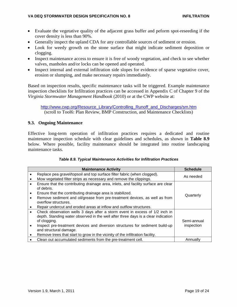
9.3. Ongoing Maintenance Effective long-term operation of infiltration practices requires a dedicated and routine maintenance inspection schedule with clear guidelines and schedules, as shown in Table 8.9 below. Where possible, facility maintenance should be integrated into routine landscaping maintenance tasks.
Table 8.9. Typical Maintenance Activities for Infiltration Practices
Maintenance Activity Schedule • Replace pea gravel/topsoil and top surface filter fabric (when clogged). • Mow vegetated filter strips as necessary and remove the clippings. As needed
• Ensure that the contributing drainage area, inlets, and facility surface are clear of debris.
• Ensure that the contributing drainage area is stabilized. • Remove sediment and oil/grease from pre-treatment devices, as well as from
overflow structures. • Repair undercut and eroded areas at inflow and outflow structures.
Quarterly
• Check observation wells 3 days after a storm event in excess of 1/2 inch in depth. Standing water observed in the well after three days is a clear indication of clogging.
• Inspect pre-treatment devices and diversion structures for sediment build-up and structural damage.
• Remove trees that start to grow in the vicinity of the infiltration facility.
Semi-annual inspection
• Clean out accumulated sediments from the pre-treatment cell. Annually
VA DEQ STORMWATER DESIGN SPECIFICATION NO. 8 INFILTRATION
Version 1.9, March 1, 2011 Page 20 of 24
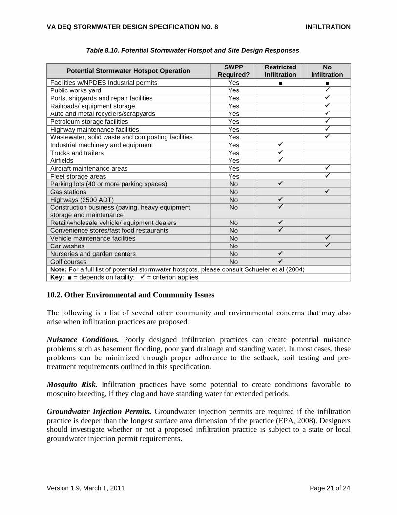
SECTION 10: COMMUNITY & ENVIRONMENTAL CONCERNS 10.1. Designation of Stormwater Hotspots Stormwater hotspots are operations or activities that are known to produce higher concentrations of stormwater pollutants and/or have a greater risk for spills, leaks or illicit discharges. Table 8.10 presents a list of potential land uses or operations that may be designated as a stormwater hotspot. It should be noted that the actual hotspot generating area may only occupy a portion of the entire proposed use, and that some “clean” areas (such as rooftops) can be diverted away to another infiltration or runoff reduction practice. Communities should carefully review development proposals to determine if any future operation, on all or part of the site, will be designated as a potential stormwater hotspot. Based on this designation, one or more design responses are required, as shown below: 1. Stormwater Pollution Prevention Plan (SWPPP). The SWPPP, required as part of a VPDES
industrial activity or a municipal stormwater permit, outlines pollution prevention and treatment practices that will be implemented to minimize polluted discharges from the on-going operations of the facility. (NOTE: This is different from the SWPPP required as part of regulated construction activities.) Other facilities or operations that are not classified as industrial activities (SIC Codes) are not required to have an Industrial VPDES permit, but may still be designated as potential stormwater hotspots by the local review authority, as part of their local stormwater ordinance (these are shown in the shaded areas of Table 8.10). It is recommended that these facilities include an addendum to their stormwater plan that details the pollution prevention practices and employee training measures that will be used to reduce contact of pollutants with rainfall or snowmelt.
2. Restricted Infiltration. A minimum of 50% of the total Treatment Volume must be treated
by a filtering or bioretention practice prior to any infiltration. Portions of the site that are not associated with the hotspot generating area should be diverted away and treated by another acceptable stormwater management practice.
3. Infiltration Prohibition. The risk of groundwater contamination from spills, leaks or
discharges is so great at hotspot sites that infiltration of stormwater or snowmelt is prohibited.
VA DEQ STORMWATER DESIGN SPECIFICATION NO. 8 INFILTRATION
Version 1.9, March 1, 2011 Page 21 of 24
Table 8.10. Potential Stormwater Hotspot and Site Design Responses
Potential Stormwater Hotspot Operation SWPP Required?
Restricted Infiltration
No Infiltration
Facilities w/NPDES Industrial permits Yes ■ ■ Public works yard Yes Ports, shipyards and repair facilities Yes Railroads/ equipment storage Yes Auto and metal recyclers/scrapyards Yes Petroleum storage facilities Yes Highway maintenance facilities Yes Wastewater, solid waste and composting facilities Yes Industrial machinery and equipment Yes Trucks and trailers Yes Airfields Yes Aircraft maintenance areas Yes Fleet storage areas Yes Parking lots (40 or more parking spaces) No Gas stations No Highways (2500 ADT) No Construction business (paving, heavy equipment storage and maintenance
No
Retail/wholesale vehicle/ equipment dealers No Convenience stores/fast food restaurants No Vehicle maintenance facilities No Car washes No Nurseries and garden centers No Golf courses No Note: For a full list of potential stormwater hotspots. please consult Schueler et al (2004) Key: ■ = depends on facility; = criterion applies
10.2. Other Environmental and Community Issues The following is a list of several other community and environmental concerns that may also arise when infiltration practices are proposed: Nuisance Conditions. Poorly designed infiltration practices can create potential nuisance problems such as basement flooding, poor yard drainage and standing water. In most cases, these problems can be minimized through proper adherence to the setback, soil testing and pre-treatment requirements outlined in this specification. Mosquito Risk. Infiltration practices have some potential to create conditions favorable to mosquito breeding, if they clog and have standing water for extended periods. Groundwater Injection Permits. Groundwater injection permits are required if the infiltration practice is deeper than the longest surface area dimension of the practice (EPA, 2008). Designers should investigate whether or not a proposed infiltration practice is subject to a state or local groundwater injection permit requirements.
VA DEQ STORMWATER DESIGN SPECIFICATION NO. 8 INFILTRATION
Version 1.9, March 1, 2011 Page 22 of 24
SECTION 11: REFERENCES Center for Watershed Protection (CWP). 2007. Urban Stormwater Retrofit Practices. Manual 3 in the Urban Subwatershed Restoration Manual Series. Ellicott City, MD. Center for Watershed Protection (CWP). 2003. New York State Stormwater Management Design Manual. Prepared for the New York State Department of Environmental Conservation. Albany, NY. Delaware Urban Runoff Management Approach. Available online at: http://www.dnrec.state.de.us/DNREC2000/Divisions/Soil/Stormwater/New/GT_Stds%20&%20Specs_06-05.pdf Maryland Department of Environment (MDE). 2000. Maryland Stormwater Design Manual. Baltimore, MD. New Jersey Stormwater Best Management Practices Manual. Available online at: http://www.nj.gov/dep/watershedmgt/bmpmanualfeb2004.htm North Shore City. 2007. Infiltration Design Guidelines. Sinclair, Knight and Merz. Auckland, New Zealand Pennsylvania. Draft Stormwater Best Management Practices Manual. Available online at: http://www.dep.state.pa.us/dep/subject/advcoun/Stormwater/stormwatercomm.htm Schueler, T., C. Swann, T. Wright and S. Sprinkle. 2004. Pollution Source Control Practices. Manual No. 8 in the Urban Subwatershed Restoration Manual Series. Center for Watershed Protection. Ellicott City, MD. Virginia Department of Environmental Quality (DEQ). 1999. Virginia Stormwater Management Handbook. Volumes 1 and 2. Division of Soil and Water Conservation. Richmond, VA.

VA DEQ STORMWATER DESIGN SPECIFICATION NO. 8 INFILTRATION
Version 1.9, March 1, 2011 Page 23 of 24
APPENDIX 8-A
INFILTRATION SOIL TESTING PROCEDURES I. Test Pit/Boring Procedures
1. One (1) test pit or standard soil boring should be provided for every 1,000 square feet of the proposed infiltration area.
2. The location of each test pit or standard soil boring should correspond to the location of
the proposed infiltration area. 3. Excavate each test pit or penetrate each standard soil boring to a depth at least 2 feet
below the bottom of the proposed infiltration area. 4. If the groundwater table is located within 2 feet of the bottom of the proposed facility,
determine the depth to the groundwater table immediately upon excavation and again 24 hours after excavation is completed.
5. Conduct Standard Penetration Testing (SPT) every 2 feet to a depth that is 2 feet below
the bottom of the proposed infiltration area. 6. Determine the USDA or Unified Soil Classification system textures at the bottom of the
proposed infiltration area and at a depth that is 2 feet below the bottom. All soil horizons should be classified and described.
7. If bedrock is located within 2 feet of the bottom of the proposed infiltration area,
determine the depth to the bedrock layer. 8. Test pit/soil boring stakes should be left in the field to identify where soil investigations
were performed.
II. Infiltration Testing Procedures
1. One infiltration test should be conducted for every 1,000 square feet of surface area for the infiltration area.
2. The location of each infiltration test should correspond to the location of the proposed
infiltration area. 3. Install a test casing (e.g., a rigid, 4 to 6 inch diameter pipe) to a depth 2 feet below the
bottom of the proposed infiltration area. 4. Remove all loose material from the sides of the test casing and any smeared soil material
from the bottom of the test casing to provide a natural soil interface into which water may
VA DEQ STORMWATER DESIGN SPECIFICATION NO. 8 INFILTRATION
Version 1.9, March 1, 2011 Page 24 of 24
percolate. If desired, a 2-inch layer of coarse sand or fine gravel may be placed at the bottom of the test casing to prevent clogging and scouring of the underlying soils. Fill the test casing with clean water to a depth of 2 feet, and allow the underlying soils to pre-soak for 24 hours.
5. After 24 hours, refill the test casing with another 2 feet of clean water and measure the
drop in water level within the test casing after one hour. Repeat the procedure three (3) additional times by filling the test casing with clean water and measuring the drop in water level after one hour. A total of four (4) observations must be completed. The infiltration rate of the underlying soils may be reported either as the average of all four observations or the value of the last observation. The infiltration rate should be reported in terms of inches per hour.
6. Infiltration testing may be performed within an open test pit or a standard soil boring. 7. After infiltration testing is completed, the test casing should be removed and the test pit
or soil boring should be backfilled and restored.