inertia relief - msc software...
TRANSCRIPT

MSC.Nastran 105 Exercise Workbook 17-1
WORKSHOP 17
Inertia Relief
Objectives:■ Create a free-free structure under a line load
■ Perform static analysis using inertia relief
■ Examine the effect of the support point
■ Compare results

17-2 MSC.Nastran 105 Exercise Workbook

WORKSHOP 17 Inertia Relief
MSC.Nastran 105 Exercise Workbook 17-3
Summary:Inertia relief is an advanced option in MSC.Nastran that allows you tosimulate unconstrained structures in a static analysis. Typicalapplications of inertia relief include modeling an aircraft in flight, anautomobile on a test track, or a satellite in space. Static analysis by thefinite element method assumes that the model contains nomechanisms and may not move as a rigid body (strain free). If eitherof these conditions exists in a conventional finite element analysis, thestiffness matrix for the model becomes singular. When MSC.Nastranattempts to decompose a singular matrix, a fatal message orunreasonable answers result.
Consequently, conventional finite element static analysis cannot beperformed on unconstrained structures. However, a method calledinertia relief is provided in MSC.Nastran for analyzing theseconditions. A simple description of inertia relief is that the inertia(mass) of the structure is used to resist the applied loadings, that is, anassumption is made that the structure is in a state of static equilibriumeven though it is not constrained.
To invoke inertia relief, you must provide a SUPORT Bulk Data entrywith a list of six non-redundent degrees of freedom that describe thepossible unconstrained motion. The easiest way to describe how touse the SUPORT entry in static analysis is if you hold the SUPORTdegrees of freedom constrained, there is no possible rigid bodymotion. If all possible rigid body motion is not described on theSUPORT entry, then the stiffness matrix is singular, and the problemeither fails in decomposition or gives unreasonable answers.
When inertia relief is specified, MSC.Nastran calculates the forcesthat result form a rigid body acceleration of the SUPORT degrees offreedom in the specified directions. MSC.Nastran then calculates thesummation of all applied loadings in the same directions.Accelerations are applied to the structure in the SUPORT directions to"balance" the applied loads is 0.0. Since the problem is notconstrained, rigid body displacement is still possible.
The next step performed by MSC.Nastran is to constrain the SUPORTdegrees of freedom to a displacement of 0.0 and provide the relativemotion of all other grid points with respect to the reference point. Thecomputed solution is the correct one, and it is relative to any rigid bodymotion that is occurring. A simple way to think of this is that thesolution coming from MSC.Nastran represents the deformation of thestructure you would see if you were standing at the SUPORT degreesof freedom.
In addition to the SUPORT entry, PARAM, GRDPNT, x and PARAM,INREL, -1 are also needed. The value x is the grid point where theSUPORT point is specified. The inertia relief method requires that arealistic mass distribution exists, and the degrees of freedom listed on

17-4 MSC.Nastran 105 Exercise Workbook
the SUPORT entry must be connected elastically to the model in allspecified degrees of freedom. (For example, degrees of freedom 4, 5,and 6 on a grid point with only solid element attached cannot be usedsince solid elements have no stiffness in these degrees of freedom.)
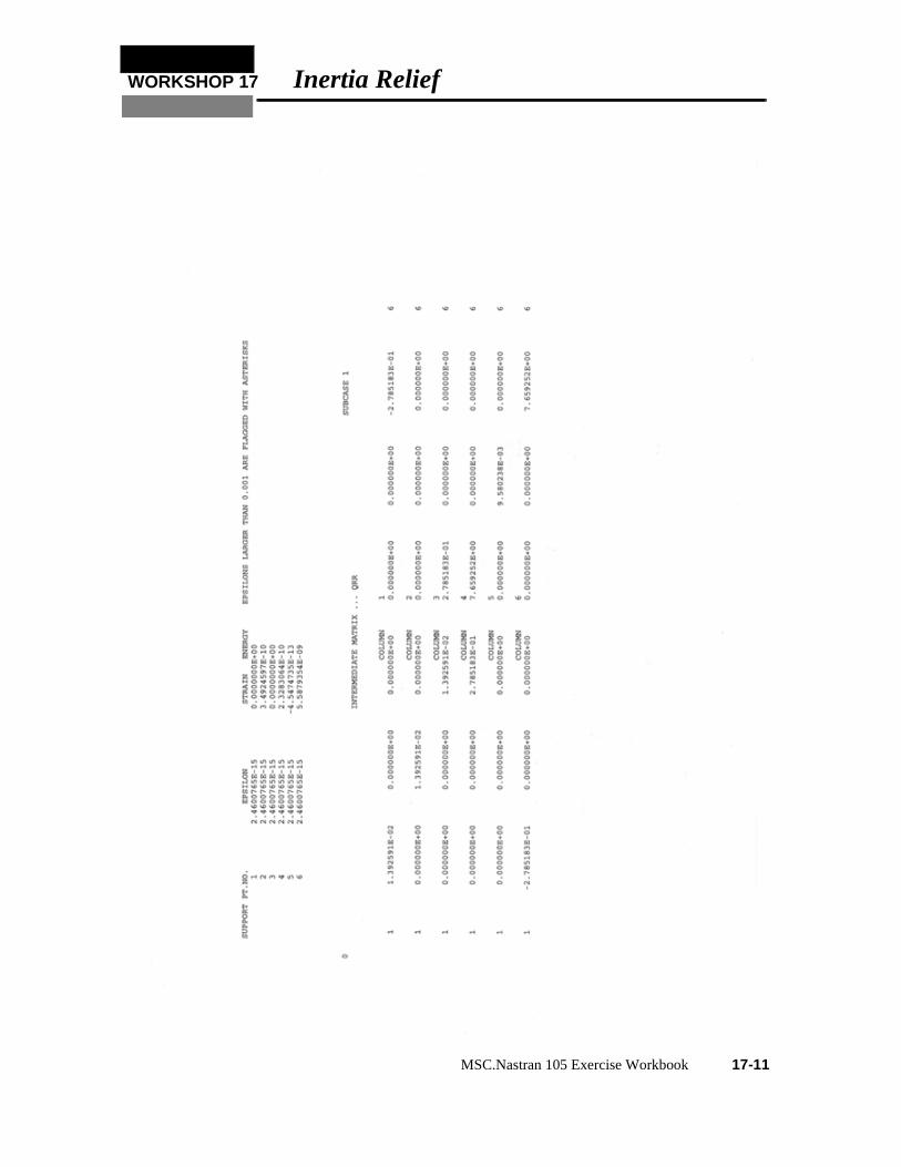
Whenever a SUPORT entry is used in static analysis, the epsilon andstrain energy printed in the table from UIM 3035 should be checked.The values printed for epsilon and strain energy in the UIM 3035 tableshould all be numeric zero (for a definition of numeric zero, seeAppendix A). The strain energy printed in this table for matrix KLRrepresents the strain energy in the model when the one SUPORTdegree of freedom is moved 1.0 unit, while all other SUPORT degreesof freedom are constrained. If the SUPORT degrees of freedom areproperly specified, the model should be capable of rigid body motion(strain-free) with no strain energy.
The values printed for the strain energy indicate the ability of themodel to move as a rigid body. These values should always bechecked. If the structure is not constrained, the values should benumeric zero, but roundoff almost always results in a small nonzerovalue.
The four CBEAM structure is to be analyzed as a free-free structurewith a thrust force acting in the Y-direction as shown and using inertiarelief. To show the effect of the SUPORT point, two runs are made,each with a different SUPORT grid point. All six degrees of freedomsfor the SUPORT point are placed on one grid point as required forSolution 101. The parameter INREL is set to -1, and the parameterGRDPNT is set to the SUPORT point, which is grid point 1 in thiscase.
10
10
10
10
5000
1
2
3
4
5

WORKSHOP 17 Inertia Relief
MSC.Nastran 105 Exercise Workbook 17-5
Suggested Exercise Steps:
■ Open a new database, prob17a
■ Create a curve 40 units in lengthGeometry: Create: Curve: XYZ
Vector Coordinate List <0, 40, 0>
Origin Coordinate List [0, 0, 0]
■ Mesh the curve with bar 2 elements and global edge length of 10Finite Element: Create: Mesh: Curve
■ Define a material called mat_1Materials: Create: Isotropic: Manual Input
Elastic Modulus = 30e6
Poisson Ratio = 0.3
Elastic Modulus = 0.286
■ Specify the cross sectino properties by using beam libraryProperties: Create: 1D: Beam
Options: Tapered Section
■ Generate a concentrated thrust load in the basic Y-directionLoad/BC: Create: Force: nodal
Force: <0, 500, 0>
1
2
.15
.15
0.1

17-6 MSC.Nastran 105 Exercise Workbook
■ Create MSC.Nastran static analysis input file. Activate SUPORT entry, PARAM, GRDPNT, x and PARAM, INREL, -1.
Analysis: Analyze: Entire Model: Analysis Deck
Solution Type: Linear Static
Solution Parameters:
■ Inertia ReliefWt-Mass Conversion 0.00259
Node id. for Wt. Generation 1
■ The following SUPORT entry will be created for inertia relief analysisSUPORT, 1, 123456
PARAM, GRDPNT, 1
PARAM, INREL, -1
PARAM, WTMASS, 0.00259

WORKSHOP 17 Inertia Relief
MSC.Nastran 105 Exercise Workbook 17-7

17-8 MSC.Nastran 105 Exercise Workbook

WORKSHOP 17 Inertia Relief
MSC.Nastran 105 Exercise Workbook 17-9

17-10 MSC.Nastran 105 Exercise Workbook
WORKSHOP 17 Inertia Relief
MSC.Nastran 105 Exercise Workbook 17-11

17-12 MSC.Nastran 105 Exercise Workbook
WO
RK
SH
OP
17Inertia R
elief
MS
C.N
astran 105 Exercise W
orkbook17-13
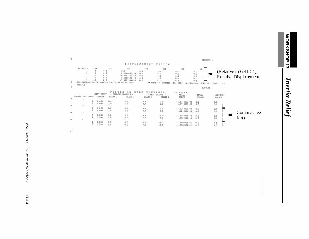
Relative Displacement(Relative to GRID 1)
forceCompressive

17-14 MSC.Nastran 105 Exercise Workbook

WORKSHOP 17 Inertia Relief
MSC.Nastran 105 Exercise Workbook 17-15
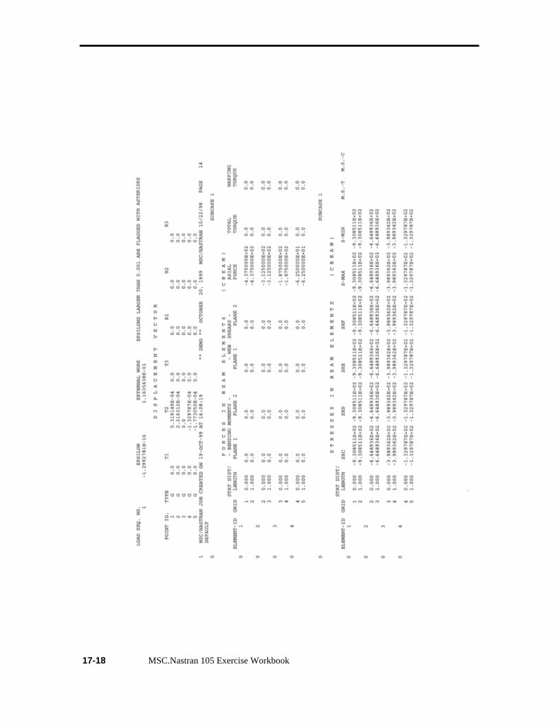
■ In this exercise, we will examine the displacement and element forces relative to GRID 3
prop 17b

17-16 MSC.Nastran 105 Exercise Workbook

WORKSHOP 17 Inertia Relief
MSC.Nastran 105 Exercise Workbook 17-17
17-18 MSC.Nastran 105 Exercise Workbook