industry automation and controls lab - cal poly
TRANSCRIPT

Electrical Engineering Department
California Polytechnic State University
Senior Project Report
Industry Automation and Controls Lab June 14th 2019
Nadir Khan
Michael Campos
Samantha Bituen
Professor Taufik

1
TABLE OF CONTENTS
Section Page
I. Abstract 3
II. Chapter 1. Introduction 4
III. Chapter 2. Background 7
IV. Chapter 3. Design Requirements 11
V. Chapter 4. Design Process 14
VI. Chapter 5. Hardware Test and Results 17
VII. Chapter 6. Conclusion 26
VIII. Appendix A. ABET Senior Project Analysis 28
IX Appendix B. Industry Automation and Controls Lab Manual 35
X. Appendix C. Bill of Materials 45
XI. Appendix D. Scheduling 46
XII. References 47
LISTS OF TABLES AND FIGURES
Table Page
3-1 Summary of Design Requirements 13
A-1 Cost Evaluation 30
C-1 Bill of Materials 45
Figure Page
1-1 Dick Morley and Associates with the Modicon 084 4
1-2 Modicon M580 ePAC 5
1-3 The Four Operational States of a PLC 6
1-4 Ladder Diagram (LD) Ladder Logic 6
1-5 Functional Block Diagram PLC Programming Language 7
1-6 Sequential Function Chart Programming 7
3-1 Level 0 Block Diagram 11
3-2 Level 1 Block Diagram 12
4-1 Final Hardware Setup Including all Component Wiring 16
5-1 Final Hardware Layout for PLC Lab Benches 17
5-2 Mounting Styles: Directly Mounted on Metal and DIN Rail on Metal 19
5-3 DIN Rail Mounting 20
5-4 Jaime Carmo Sanding a DIN Rail 20
5-5 Din rail holes for mounting on the bench 21
5-6 Schneider Electric instruction sheet for mounting the HMI 22
5-7 Tryone Gooseneck Tablet Stand sold on Amazon 24
5-8 HMI mounting method with the Tryone Gooseneck Arm 25

2
5-9 Side view of the clamp used and arm bent into shape 26
B-1 Ladder Logic Rung 35
B-2 LD Variables Table 36
B-3 Labeling Relays and Relay Coil 36
B-4 Simulating the LD LED Program 37
B-5 Setting Different Values to Relays 37
B-6 New Project Hardware Selection Screen 38
B-7 PLC Configuration Layout Example 39
B-8 Elementary Variables for the Simulation 40
B-9 Creating a New Section Screen 40
B-10 Simulation FBD Layout 41
B-11 Example of Animation Table Results (by Forcing Voltage 1 & 2 Values) 41
B-12 DFB I/O Variable List 42
B-13 FBD Layout after Transferring the Old Schematic into the New Schematic 43
B-14 FBD Schematic with New DFB I/O Variables 43
B-15 FFB Input Assistant Generation for Project 44
B-16 FBD Schematic with New DFB Placed 44
B-17 Placing the DFB into a Custom Library Saves the Circuit for Future Use 45
D-1 Fall Quarter 2018 Gantt Chart 46
D-2 Winter Quarter 2019 Gantt Chart 46
D-3 Spring Quarter 2019 Gantt Chart 46
3
Abstract:
This work details our efforts to build a new industrial automation lab for the Cal Poly San Luis
Obispo Electrical Engineering department from the ground up. Thanks to a donation of Modicon
M580 programmable logic controllers (PLCs) from Schneider Electric, we built a lab hardware
layout to support a learning environment for students. The Electrical Engineering department
currently doesn’t offer any courses for students to learn about automation in topics more closely
following the topics learned in their curriculum. It will be beneficial for the school and the
students to have graduates in the major with some knowledge of controls in the field of industrial
automation. Many large corporations including Rockwell Automation, Schneider Electric,
Siemens, Yokogawa, and Mitsubishi Electric all have substantial jobs in the workplace. For the
lab, research led to multiple different designs of how to layout the DIN rail and other equipment.
Our final layout placed a strong emphasis on reducing cost, including removing a metal
backplane and using a flexible mounting system for the touchscreen. The results shown in the the
work illustrate the flexibility of the lab bench setup moving forward, as future students will need
room for growth as they continue to develop the lab. Additional time was spent developing lab
instructions for the first lab of the course, a simple introduction into programming with ladder
logic and function block diagram.

4
1. Introduction
In 1968 a man named Dick Morley built the first programmable logic controller called
the Modicon 084 [4]. Prior to this invention, industrial automation processes were controlled by
hard-wired relay systems which were complicated and expensive to modify. The device made the
time, effort, and cost to change a process significantly reduced while also simplifying the
communication between process devices. In 1996 Schneider Electric released a high-
performance Modicon Premium for large applications that pioneered a whole new class of PLC,
the programmable automation controller (PAC). In 2003, they added embedded web server
capabilities which marked a turning point for making network communications easier and more
reliable. In 2007, the Modicon M340 simplified configuration and operation by using functions
like a native USB port, SD card slot, ethernet, modbus and a battery-less design which removed
the need to swap batteries periodically in remote locations. This all led to the Modicon M580 in
2013; a controller designed with transparency, flexibility, and sustainability.
Figure 1-1: Dick Morley and associates with the Modicon 084 [17]
The Modicon M580 donated to Cal Poly SLO as shown in Figure 2 holds the title as the
world's first ePAC controller. The product is designed with an ethernet backbone to optimize

5
connectivity and communications. The M580 fully supports FDT Technology, an international
standard for asset integration and data delivery with broad acceptance in the automation industry
[13].
Figure 1-2: Modicon M580 ePAC [18]
There are four basic states of operation for PLCs: input scan, program scan, output scan
and housekeeping [27]. These four states are continuously run in a loop to ensure that the device
is constantly processing data as seen in Figure 1-3. Input scan detects the states of all input
devices connected to the PLC. Program scan executes the user created logic built in software.
Output scan energizes or de-energizes all output devices that are connected to the PLC.
Housekeeping includes communications with programming terminals and internal diagnostics.
Housekeeping tasks can also be created by the user.
Figure 1-3: The four operational states of a PLC [27]
6
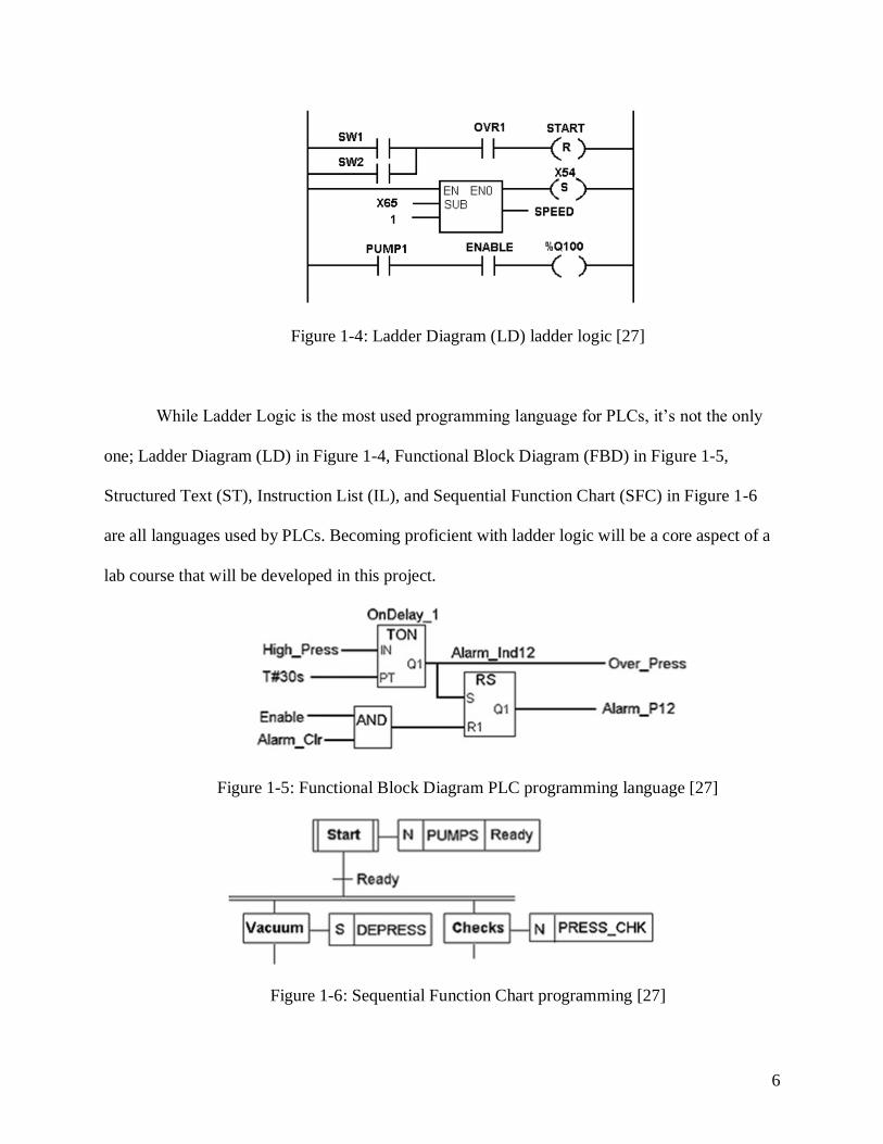
Figure 1-4: Ladder Diagram (LD) ladder logic [27]
While Ladder Logic is the most used programming language for PLCs, it’s not the only
one; Ladder Diagram (LD) in Figure 1-4, Functional Block Diagram (FBD) in Figure 1-5,
Structured Text (ST), Instruction List (IL), and Sequential Function Chart (SFC) in Figure 1-6
are all languages used by PLCs. Becoming proficient with ladder logic will be a core aspect of a
lab course that will be developed in this project.
Figure 1-5: Functional Block Diagram PLC programming language [27]
Figure 1-6: Sequential Function Chart programming [27]

7
2. Background
Industrial power controls and automation play important roles in the power industry.
Many power equipment ranging from motors used in HVAC (Heating Ventilating Air
Conditioning) system and manufacturing plants, Line Tap Changing transformers, relays,
lighting system, make use of industrial power controls typically implemented by PLCs
(Programmable Logic Controllers). Despite their importance in power industry, the electrical
engineering department at Cal Poly State University currently does not offer any course related
to the subject. This has been a gap in the power program specifically especially realizing that
some other California State Universities (CSU) have been offering courses in industrial controls
and automation or courses that provide some coverage on PLCs. Some CSUs such as Fullerton,
Chico, Fresno, and San Bernardino appear to have lab courses offered which use PLCs
[10,12,14,20]. However, it is not clear whether these courses include actual hands-on exercises
with PLCs and power equipment. At Cal Poly, the control system courses are more focused on
the theoretical aspects with no coverage of any topics related to PLCs. It is therefore important
for the electrical engineering department in general and the power program in particular to
include at least one course where students get to learn and practice the PLCs for power controls
and automations. This will further strengthen the learn-by-doing philosophy of Cal Poly and will
better prepare their graduates in the power industry.
In this project, a laboratory course on Industrial Power Controls and Automation will be
developed using PLCs recently donated by Schneider Electric. The lab course will be designed
with a close partnership with Schneider Electric to ensure that the course will be effective in
preparing students with some skills in PLCs. As part of the plan, the lab course will have
experiments which will expose students to real world challenges and issues in the world of

8
automation and controls. In doing, the lab course should not overlap with any existing PLC
courses at Cal Poly, but rather it should complement them. Lastly, since we are not the first to
develop such a course, any existing lab courses outside of Cal Poly that have similar learning
outcomes will be used as references so as not to reinvent the wheel. Many of these schools are
community colleges and trade schools in California wherein they offer a program which heavily
involves PLCs and can be completed in two years or less.
Outside of the U.S., there is the Annasaheb Dange College of Engineering & Technology
in India which outlines some useful course outcomes on teaching a state-of-the-art PLC lab for
education [19]. The course contains demonstration based learning instead of lecture sessions and
testing on memorization. Students have the opportunity to apply what they learn about a relay
logic system by seeing it hardwired with a PLC rather than just learning the theories in
classroom. In addition, students also learn about the nature of PLCs which provide the
connection between different engineering fields and may incorporate topics such as electric
motors, frequency controllers, and Supervisory Control and Data Acquisition (SCADA) systems.
For the proposed lab course, the goal is to replicate as much as possible an industrial
environment with knowledge applicable to a full time career.
Another example of a PLC course outside of the U.S. is found at a university in Thailand.
The university developed a lab course that teaches engineering students about the basic
principles of PLCs. In doing so, the university focuses on the many benefits of using PLCs over
outdated relay control logic such as: higher efficiency, more flexibility, faster response time, and
easier troubleshooting. The university believes that teaching to get student’s understanding of the
principles and operation of PLCs is important, especially for students who want to enter the
industrial controls and automation industry. However, the university also noted some drawbacks

9
when it comes to developing a PLC lab course. One main issue is stated as “However, problems
and obstacles in the study and experiment on PLC is the rapid pace of PLC technological
development, with new models and innovations continually being introduced by manufacturers”
[4]. Due to the growing demand of PLC applications, the PLC manufacturers are constantly in
pursuit of newest and most advanced PLC for industry consumers. A PLC lab cannot become
stagnant in terms of technical concepts because the information will be useless if it's not up to
industry standards.
Another issue with learning PLCs is that just merely using a PLC does not necessarily
enable or enforce students to understand how they work. With more complex modern systems,
often it is difficult to understand the role of PLCs in the big picture. Students can delve right into
the PLC programming without getting the full understanding of why the PLCs are utilized. To
address these problems there is a need to develop GUI to help students visualize the overall look
at the PLC system while providing students with adaptive interactive practice. The GUI could be
designed to allow students to visualize the PLC concepts. That is, they were intended to
represent not the physical appearances of PLC, but rather their theory of operation. GUI allows
students to manipulate components of the animation to see what would happen if a certain
condition occurs in the system or what if tests. For the proposed project, the touch screen human
machine interface (HMI) donated by Schneider Electric will be incorporated into the lab
experiments to help create GUIs for each lab.
In summary, the goal of this project is to develop a PLC lab that will instruct Cal Poly
students on how to use a PLC and understand all the different applications and devices it can
interface with. The main objectives of the PLC course in undergraduate engineering program are
[1]:
10
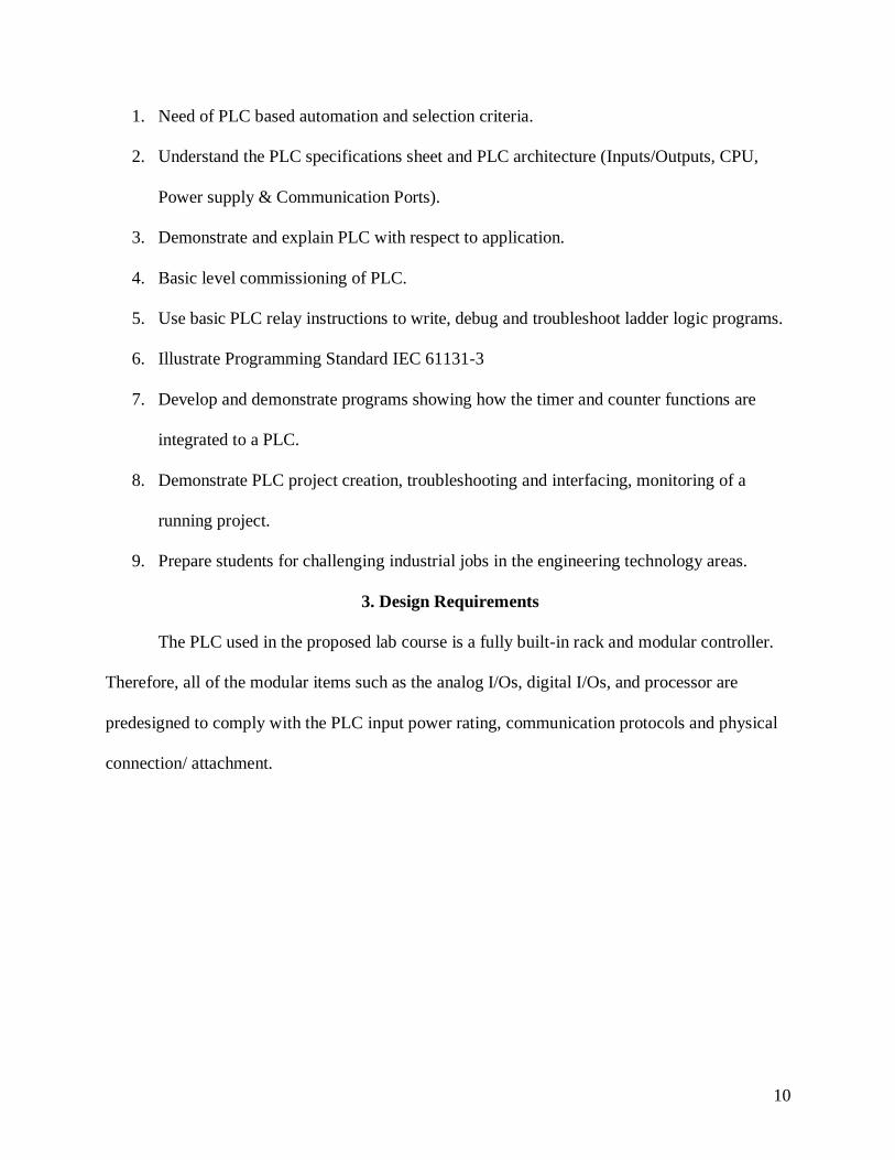
1. Need of PLC based automation and selection criteria.
2. Understand the PLC specifications sheet and PLC architecture (Inputs/Outputs, CPU,
Power supply & Communication Ports).
3. Demonstrate and explain PLC with respect to application.
4. Basic level commissioning of PLC.
5. Use basic PLC relay instructions to write, debug and troubleshoot ladder logic programs.
6. Illustrate Programming Standard IEC 61131-3
7. Develop and demonstrate programs showing how the timer and counter functions are
integrated to a PLC.
8. Demonstrate PLC project creation, troubleshooting and interfacing, monitoring of a
running project.
9. Prepare students for challenging industrial jobs in the engineering technology areas.
3. Design Requirements
The PLC used in the proposed lab course is a fully built-in rack and modular controller.
Therefore, all of the modular items such as the analog I/Os, digital I/Os, and processor are
predesigned to comply with the PLC input power rating, communication protocols and physical
connection/ attachment.

11
Figure 3-1: Level 0 Block Diagram [28]
Figure 3-1 displays the level 0 block diagram and Figure 3-2 displays the level 1 block
diagram of the PLC system of the proposed lab course. The 120V input is supplied from the lab
room’s outlet and connects to the PLC circuit breaker. The PLC circuit breaker is an Allen
Bradley circuit breaker rated at 1.6 Amp, 1 pole, 48 VDC, 277 VAC. The circuit breaker is rated
at 1.6 A to protect the PLC power supply, which has a typical current rating of ~1.1A. The PLC
digital inputs have a voltage rating of 24 VDC at 3.5 mA. The digital voltage output is 0-24
VDC. The analog inputs/outputs have a voltage rating of -10 to +10 V and a current rating of -20
to +20 mA.

12
Figure 3-2: Level 1 Block Diagram
There is a second power supply which powers the touchscreen (HMI) and the Ethernet
switch. This second power supply also has its own circuit breaker, which is also an Allen
Bradley breaker rated at 3 Amp, single pole, 48 VDC, 277 VAC. The 3 Amp circuit breaker will
protect the second power supply, which is rated at 2.8 Amp input. The 3 Amp circuit breaker is
also connected to the lab room’s outlet of 120 VAC. The second power supply which powers the
HMI and Ethernet switch outputs 24 VDC and a maximum output current of 5 Amps.
Table 3-1 lists and summarizes the engineering design specifications for the PLC setup of
the proposed lab course.

13
Table 3-1: Summary of Design Requirements
Requirement Engineering Requirement
Lab bench PLC mounting ● 35mm x 7.5mm x 2m symmetrical DIN rail
for mounting components
● DIN rail length for lab bench - Machine cut
to 6 feet
● 16 AWG stranded wire
Modicon X80 I/O Platform IP degree of protection: IP20
Product Compatibility:
● BMXCPS power supply
BMXP34 processor
I/O Channels:
● Discrete I/O 4096
● Analog I/O 1024
● Expert 144
8-slot Ethernet + X-bus rack Power consumption: 2W
Fixing Mode:
● By 4 M6 screws plate
● By clips 35mm symmetrical DIN rail
● By 4 screws 4.32...6.35 mm panel
Circuit Breaker (BMXCPS3500) Typical PSU input current:
● 1.104Arms @115Vrms
It (for rating external breaker)
● 0.1As @115Vrms
● 0.15As @230Vrms
Breaker rating: 1P, 1.6A, ~277V, 50/60Hz
Circuit Breaker
(ABL8REM24950)
● Mounting support: 35 x 7.5 mm symmetrical
DIN rail
● Max input current: 2.8A
● Breaker: 1P, 3A, ~277V, 50/60Hz

14
Touch Panel HMI
(HMISTU855)
● Display resolution: 320 x 240 pixels QVGA
● Power consumption - 6.8 W
● Integrated connection USB 2.0 type A
● Supply voltage limits 20.4...28.8 V
Unity Pro Programming methods:
● Structured Text (ST)
● Function Block Diagram (FBD)
● Ladder Logic (LL)
4. Design Process
The design process for this project focuses on obtaining the correct dimensions for the
PLC system setup. The lab contains six lab desks that are 6 feet in length each. The quickest and
most efficient method of mounting the PLC and other hardware to the desk was to attach a steel
DIN rail across the back of the desk to span from edge to edge. Incorporating steel DIN rails in
PLC mounting is a standard primarily used in industry. DIN rails standard measurements are
usually in meters. The DIN rails ordered for this lab were 35mm x 7.5mm x 2 m each which
exceeds the length of the lab desks; therefore, the din rails were cut and grinded in order to
perfectly fit the lab desks. Also, a ⅝ inch diameter hole was punched into the DIN rail to allow a
steel bolt insertion. Once the DIN rail was complete, the rest of the setup process was relatively
straightforward.
The mounting items used in all of the lab desks were: ½ inch diameter steel nut (2 inches
in length), and ½ inch diameter washers. There are two sets of lab desks in the lab room (3 lab
desks in each set), therefore, the mounting for the different sets was slightly different. One set of
desks required a 1-inch square washer and a spring attached to a metal bracket that connects to a
steel bolt. The other set of desks did not require these two extra items. At the end of the DIN rail

15
mounting, a total of: twelve steel bolts (2 for each lab desk), twelve ½ inch washers (2 for each
lab desk), six 1-inch square washers (two washers per desk on 3 of the lab desks), and six spring-
metal brackets (two per desk on 3 of the desks) were used.
Next, all of the hardware was mounted (clipped onto) the DIN rail. Most PLC hardware
components are DIN rail compatible, meaning that they can be clipped onto a DIN rail. The PLC
rack (which physically holds up the PLC processor and the digital/analog I/O cartridges) has a
slot in the back with tiny springs to allow the insertion of a 35mm x 7.5mm din rail. The circuit
breakers, power supply, terminal blocks and ethernet switch all have slots in the back to clip onto
a DIN rail.
Lastly, the wiring. PLC hardware (including digital/analog I/O cartridges) is compatible
with 14-22 AWG wire. The wire used in this lab is 16 AWG. The wiring begins with the circuit
breakers. There are two power cables per lab desk, one power cable per circuit breaker. The
power cables were cut and stripped. The positive cable (live wire) connected to the circuit
breaker, the neutral wire connected to a terminal block, and the ground wire connected to a
grounding terminal block. From there, the live wire, neutral wire and ground wire are connected
to the PLC power supply appropriately. The same process was repeated for the circuit breaker
connecting to the 24V power supply that connects to the Touchscreen (HMI) and ethernet
switch. Finally, the positive/ground/neutral terminals from the 24V power supply were
connected to the appropriate terminals on the Touchscreen and ethernet switch. The wiring
diagram can be seen in Figure 4-1.

16
Figure 4-1: Final hardware setup including all wiring to components
17
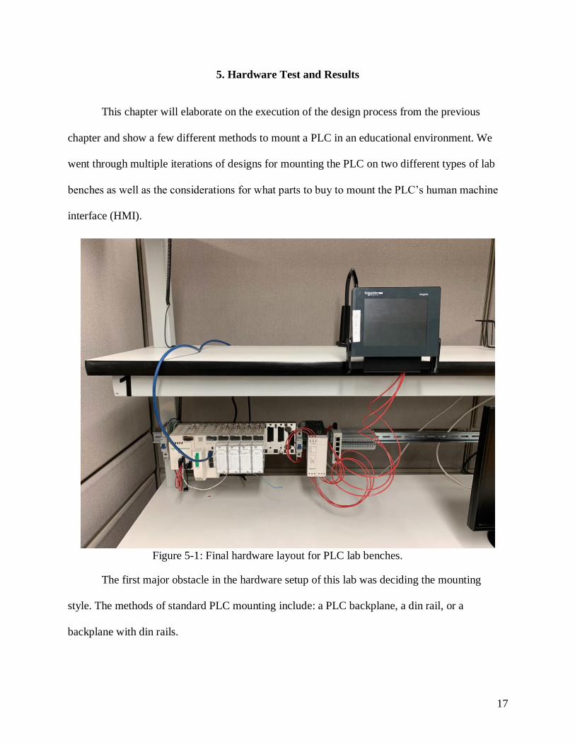
5. Hardware Test and Results
This chapter will elaborate on the execution of the design process from the previous
chapter and show a few different methods to mount a PLC in an educational environment. We
went through multiple iterations of designs for mounting the PLC on two different types of lab
benches as well as the considerations for what parts to buy to mount the PLC’s human machine
interface (HMI).
Figure 5-1: Final hardware layout for PLC lab benches.
The first major obstacle in the hardware setup of this lab was deciding the mounting
style. The methods of standard PLC mounting include: a PLC backplane, a din rail, or a
backplane with din rails.

18
A PLC backplane is convenient for big, vertical stations. Having a backplane could allow
easy installation for various hardware machines such as a PLC or power supplies. The left
picture of Figure 5-2 displays a PLC backplane [25]. A PLC backplane provides many benefits
such as easy installation, secure mounting, visibility (since everything is installed in the same
station) and the robustness to hold many different machines. The cons of having a backplane
were the deciding factors for not installing it in this lab. Since a backplane is usually setup within
its own standing station, all of the metals can be drilled and fit together nicely. The metal
backplane would not work well with the desks in this lab. The desks don’t allow much vertical
space for mounting and buying sheets of metal to span across the back of the desk would be very
time consuming since the sheets of metal would have to be drilled and cut every time a new
piece of equipment is added to the mounting setup. Wood can also be used as a backplane but the
same problem arises in terms of time consumption; a hole would have to be cut every time a new
piece of equipment was added.
The other mounting method is a backplane with din rails. The right picture of Figure 5-2
displays a backplane with din rails [26]. This method provides many of the benefits of the
standard backplane. Having the din rails on the backplane would allow for easier installation
since the PLC rack, power supplies and terminal blocks are din rail compatible (they can easily
be clipped onto a din rail). However, this method does not work for this lab for the same reasons
stated before which consist of the desk not having much vertical space for mounting and large
time consumption.

19
Figure 5-2: PLC Mounting Styles: the PLC is mounted directly onto metal (left), the PLC is
mounted onto DIN rails which are mounted on the metal (right).
The third style of standard PLC mounting is using a din rail. This method was chosen for
this lab because it is the easiest of all three. A din rail is very convenient for horizontal mounting
and it allows for easy installation of the hardware since all of the parts can be clipped onto the
din rail. This was the most cost effective style since no metal or wood backplanes are needed.
This method worked best since the desks are 6 feet wide (standard din rail lengths are two
meters, slightly over 6 feet) and have space for lots of horizontal mounting. Figure 5-3 displays
the din rail mounting used in this lab.

20
Figure 5-3: Din rail mounting, note the large amount of unused space.
The next obstacle in the mounting process was to install the din rail onto the legs of the
desk. Chapter 4 discusses the different sets of desks as well as the tools needed for each desk in
this lab. Students without permission to use the machine shop at school aren’t able to cut and
grind the din rail on their own. Therefore, assistance was provided to install the din rails. Figure
5-4 displays Jaime Carmo, a greatly respected technical assistant in the EE Department at Cal
Poly SLO, belt sanding the din rails to fit onto the lab desks.
Figure 5-4: Jaime Carmo sanding a din rail.

21
The edges of the din rail were also sanded to smoothen the sharp corners. Figure 5-5 displays the
holes that Jaime cut into the din rails that allowed a bolt/screw to go through for mounting.
Figure 5-5: Din rail holes for mounting on the bench
Another issue that arose once all of the hardware was mounted was the weight
distribution on the din rail. Even though the steel din rails are robust, the weight of the PLC,
circuit breakers, power supplies, digital I/O, and all of the other equipment created a small sag in
the middle of the din rail. Having all of the equipment mounted towards the middle of the din rail
compromised the elastic and compressive strength integrity as well as its stiffness and stability.
In order to avoid compromising the din rail material properties, all of the equipment was moved
to the edge of the din rail where most support was provided by the desk leg. Figure 5-3 displays
the PLC equipment on the left side of the din rail. This greatly reduced the sag in the middle of
the din rail.
Mounting the touchscreen (HMI) with a sturdy grip was rather difficult at this point in the
labs development, due to the changing nature of the bench layout. To begin the process of
choosing the mounting mechanism we had some considerations to keep in mind. Since the lab is
still early in development, we do not know what future equipment may fill the rest of the lab

22
bench space. We also wanted something that was not very expensive, in case the mounted
method wanted to be altered/changed in the future of the course. The main goal was just to free
up the main lab bench space below the PLC so that students have room to work with the PLC
wires as well as make measurements. Due to these constraints we had to ignore the
recommended mounting method seen in Figure 5-6.
Figure 5-6: Schneider Electric instruction sheet for mounting the HMI.
Figure 5-6 shows the method of mounting the touchscreen to a flat surface such as metal
or wood. The automation industry tends to use metal due to the already designed custom metal
boxes often holding the PLC with various other components. Since we had already avoided the
use of metal mounting sheet for the back of the lab bench and PLC, we once again had to think
of a different method for mounting the touchscreen. The instructions from Schneider Electric
involve a maximum 0.236 in. flat sheet (2) to be wedged between the two portions of the HMI.

23
Depending on the force holding the HMI pieces (1 & 3) together, the screen may rotate
clockwise or counter clockwise if not secured properly. This is why the tee (5) in the diagram
exists, to prevent the HMI from rotating from its default horizontal position. Our method had to
include the compression for both pieces while also making sure the HMI would not rotate out of
position anytime when touched or due to gravity.
We spent a lot of time brainstorming different ideas, including taking TV stand legs and
retrofitting a metal sheet onto two legs to be used as a stand. This created a number of issues,
mainly being that the TV stand legs would waste a lot of space and are relatively expensive for a
simple design. That whole concept of a TV type stand would require engineering the entire stand
from scratch just for the purpose of mounting the touchscreen. The idea was to have the stand for
touchscreen disconnected from the whole lab setup so that it could be easily moved or readjusted
when necessary. We began to realize that buying any legs to mount a metal sheet onto was too
complicated due to the different and often large sizes of legs and how most of them were not
made to have a metal sheet mounted onto them. On top of these issues, we did not want the
touchscreen to be recessed far back on the top portion of the lab bench, as when students are
seated, they would not be able to read information from the screen without standing up. A simple
stand would also be relatively unstable when the device is being touched by users, it would
require drilling into the table to make sure it wouldn’t recess back every time it was being used.
We even considered VESA mounts commonly used for PC monitors that would clamp onto a
table and suspend the HMI in the air with a metal arm. Most of these mounts were too expensive,
but the main issue with VESA mounts is that the supporting arm covers the connection of the
display module to the panel adapter; both of these components are centered and would be
interrupted by a VESA arm. The idea of clamping to the side of the table was good though
24
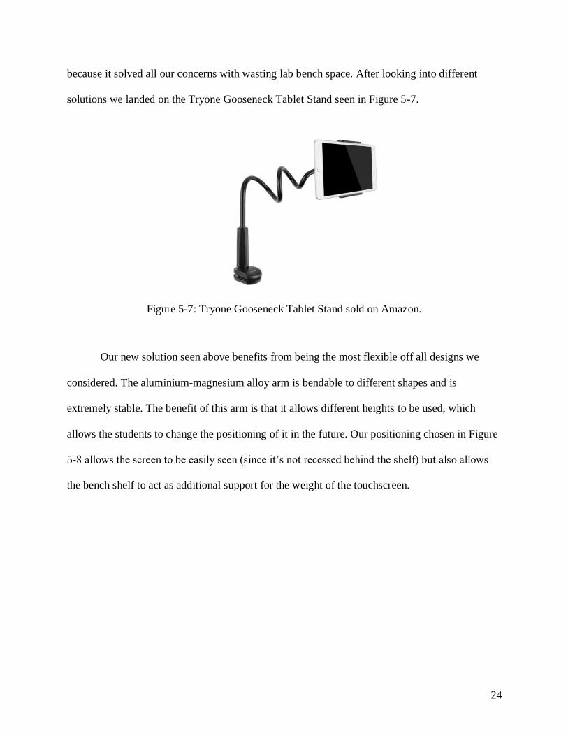
because it solved all our concerns with wasting lab bench space. After looking into different
solutions we landed on the Tryone Gooseneck Tablet Stand seen in Figure 5-7.
Figure 5-7: Tryone Gooseneck Tablet Stand sold on Amazon.
Our new solution seen above benefits from being the most flexible off all designs we
considered. The aluminium-magnesium alloy arm is bendable to different shapes and is
extremely stable. The benefit of this arm is that it allows different heights to be used, which
allows the students to change the positioning of it in the future. Our positioning chosen in Figure
5-8 allows the screen to be easily seen (since it’s not recessed behind the shelf) but also allows
the bench shelf to act as additional support for the weight of the touchscreen.

25
Figure 5-8: HMI mounting method with the Tryone Gooseneck arm bent into a different shape.
Since the clamp is meant to hold up tablets, its clamping force pushing inwards from both
sides into the touchscreen insures a very stable grip. The wedge in between the display module
and the panel adapter sits below the centered connection also ensures HMI won’t fall since it is
being suspended off the table. With this final solution for the touchscreen, it can be easily moved
and height adjusted without drilling into the table or created a new stand from scratch. Although
we are using the arm for a slightly different purpose than it was intended for, it allows the HMI
to be conveniently placed and accommodate for different equipment entering into the lab in the
future. Figure 5-9 helps illustrate the minimal amount of space used by the mounting method for
the touchscreen.

26
Figure 5-9: Side view of the clamp used and arm bent into shape.
6. Conclusion
This project entails the initial setup and development of an Industrial Power and Controls
lab located in building 20 room 150. Developing a lab hardware layout from scratch presented a
much more complex problem than expected. Due to the lack of experience with the Electrical
Engineering department with PLC’s, we invested a large portion of time simply to learn
everything about the Industrial Automation industry and how to go about mounting the PLCs in
a much different environment used in industry. We also spent some time debating how Electrical
Engineering students should learn their first lab and be introduced to programming PLCs.
Most of the choices made for mounting the PLCs were due to cost being the most
important factor for an educational environment. Choosing to simply mount the DIN rail directly
onto the lab bench and avoid mounting a large metal sheet on the back of the bench was directly

27
a decision to save money. The PLC still benefits from facing the user directly, but we avoided
buying, retrofitting, and sanding the metal to meet the sizes of each bench. Another issue with
mounting a metal sheet early into the process is due to the dynamic environment of lab
development. We had no blueprints or a set list of equipment of what had to be included for the
lab course. Buying and cutting metal to specific sizes would mean there would be very little
room for shifting equipment around and even swapping out equipment for others late into the
future. As future students help develop the PLC labs, they will help determine what equipment is
necessary to build out and make use of the open spaces on both the DIN rail and the shelf of the
lab benches above the PLC. Since a large portion of open space exists on the rail, future students
may choose to relocate certain items and place them effectively close to each other to reduce the
length of wires and simplify the visual appearance of the lab. We also recommend to add some
sort of middle support for the DIN rail, as the addition of future devices may cause the rail to
sag. If and only if a final layout of future equipment gets developed, we also believe that
mounting a metal sheet may be beneficial to take use of space above and below the PLC’s
current location.
In addition to the lab hardware layout, the task of learning how to navigate through the
software to communicate with PLCs, Unity Pro, posed an equally difficult challenge when
developing the simulations and procedures of experiments. Due to Schneider Electrics Unity Pro
software having limited examples and learning tutorials online, we relied heavily on a
representative from Schneider Electric, Derrick Baker, to help teach us the basics for
programming the Modicon M580. In the future, we recommend new students developing the lab
to request to take some of the paid onsite training sessions to help develop more advanced skills
specific to the Modicon M580. Derrick Baker deserves a large amount of credit for helping teach

28
us the couple of times he came to Cal Poly; any future training sessions taught by him at our
school would also alleviate scheduling issues of students having to visit Schneider Electric in
person. Additional training related to the PLC in our lab would mean that future students
developing the course may exploit the equipment for as many of the features as it offers.
Selecting Ladder Logic (LL) and Function Block Diagram (FBD) programming languages for
this course allows students to see visual representations of their circuits, which is easier to detect
incorrect wiring or variable placement compared to structured text or instruction list
programming. While the simulation schematics for Unity Pro may have a similar layout to other
circuit simulation software, setting up the function block and relay I/O has a different process
that students would not be as familiar with. Instructions for this setup are written in great detail
to prevent error or harm to the hardware.
Appendix A. ABET Senior Project Analysis
Project Title: Industry Automation and Controls Lab
Students: Michael Campos, Nadir Khan, Samantha Bituen
Advisor: Taufik
1. Summary Of Functional Requirements:
a. This lab is being developed in order to expose and prepare students who want to
enter the industrial controls and automation industry. The lab is centered around
the use of PLC’s and will focus on electrical engineering concepts such as
controlling electrical power, current, or voltage.
2. Primary Constraints

29
a. There are a couple of constraints that will make this project difficult for us to
complete. First of all, we don’t have the same size desks for all of the lab. Three
of the lab benches are a different type of desk than the other three. This means
that we will have to improvise and possibly drill the back plane for the mounting
of the PLC setup directly into the stands of each desk. This also limits the amount
of vertical space we will have between the desk and the top shelf of the desk. The
next constraint is to figure out exactly what materials we need and where to buy
them from. For this constraint we can can consult with our Schneider Electric
contact person, but have to ensure we can still find relative cheap prices online in
case they try to upsell us. Another constraint is to make sure that the hardware
setup of the lab is completed in time for us to begin developing the first few
experiments of the lab.
3. Economics
a. What will impact the result?
i. Human Capital: This lab will teach students how to use PLC’s and prepare
for jobs using PLC software and hardware.
ii. Financial Capital: PLCs growth and implementation is expected to
increase by 34% just in the United States, therefore, preparing students
with this lab will create better engineers for companies to benefit from.
iii. Natural Capital: This lab will consume a lot of electrical power since there
will be 6 lab stations each powering a PLC power supply and a touch
screen power supply. There are also computers that will need power.

30
iv. Costs: The components for the lab accumulate to nearly $67k since there
are 6 lab stations. Each lab station will comprise of the same components
listed in Table 5. The amount of time it will take to develop this lab will
be around 20 weeks (winter and spring quarter). Table 6 shown below
displays the component cost and labor cost for the development of the lab.
There is only 2 of us developing this lab and we plan to work at least 4
hours a week on this lab. The labor cost will be $11.00/hr (minimum
wage).
Table A-1: Cost Evaluation
Purchase Cost Explanation
Modicon M580 Processor (6)
Touch Screen Monitor (6)
Circuit Breakers (12)
Touch Screen Power Supplies (6)
Metal Backplanes (6)
Din Rails (6)
Terminal Blocks (12)
$60,000
$2400
$1800
$1500
$450
$150
$300
Estimated Component Parts
Labor 80 Hrs ($11/hr) Minimum Wage Labor Cost
Total Cost $67,480
4. If manufactured on a commercial basis
a. For this lab we are not going to be manufacturing any products, we are only create
a custom lab for the lab benches exclusive to our EE department. There are
currently no plans to sell or manufacture any portion of the lab.
5. Environmental

31
a. The environmental impacts of our project are mainly due to the electricity usage
of the lab itself. Electricity does not always come from clean (renewable) sources;
this means that we must ensure that the development of the lab and usage of the
universities money is not put to waste on an ineffective learning experience.
There are additional costs for the parts we purchase. The metal backplane, circuit
breakers, terminal blocks, and DIN rail can all be recycled since they are made of
metal and plastic.
6. Manufacturability
a. Manufacturing of this project will not be conducted. Everything built in the lab
will be proprietary and not used in other settings.
7. Sustainability
a. Describe any issues or challenges associated with maintaining the completed
device.
i. One issue with maintaining the device is the circuit breakers and the fuses
protecting the PLC and touchscreen. We have to make sure the fuses are
sized properly so that any power surges will not harm the expensive
components. The mounting method for the touchscreen may break over
time. If the clamp screw is over tightened it may break.
b. Describe how the product impacts the sustainable use of resources
i. Since the components we are using are built to last, we are ensuring that
additional purchasing of hardware due to poor craftsmanship will not
affect the environmental footprint of the lab. Additional warnings and

32
safety labels can be added to ensure that the equipment is treated with care
from future students using the lab.
c. Describe any upgrades that would improve the design of the project
i. Currently we are not expert metal workers and don’t have much
experience with construction. If we had an experienced construction
worker to assist building the hardware of the lab, we could account for any
design issues we might miss due to lack of experience with long term
durability of materials. This could allow the projects hardware layout to be
designed for both a greater convenience of use and device stability when
mounted to the lab benches.
d. Describe any issues or challenges associated with upgrading the design
i. We don’t have the funds to hire an experienced machinist for the project,
so we may have to ask for a donation of their time and energy.
8. Ethical
a. The lab course must be designed in order to challenge the enrolled students.
Making the lab “too easy” wouldn’t really teach the students or engage their
interests in PLCs. The lab must also “feel” like a 400-level 2 unit lab course. We
also can’t make the lab “too challenging” because this is an intro lab course to
PLCs.
9. Health and Safety
a. There are several safety factors that will be considered in the development in this
lab. The PLC and touch screen power supplies will be powered from 120Vrms
AC voltage. In the case of an electrical surge, there will be 2 circuit breakers in

33
each lab station that will protect the power supplies. Also, there are 24V DC I/O
pins on the PLC. The students will be warned of this, careful circuit wiring and
precaution will be heavily stressed at the beginning of the lab.
10. Social and Political
a. This lab course prepares and teaches students how to use PLC software and
hardware. Students taking this lab course will be better prepared to enter the
Industrial Controls & Automation industry, thus, giving these students an
advantage over students not enrolled in the lab course.
b. This lab uses Schneider Electrics Modicon M580 PLC. Even though the
programming for PLCs (ladder logic or functional block diagrams) is typically
universal, enrolled students may favor the Schneider’s Modicon over competing
PLCs.This can create a financial or economic advantage for Schneider Electric
over its competitors.
11. Development
a. In order to be able to write an instructional manual for this course, the senior
project team participated in workshops with a representative from Schneider
Electric to learn to operate and communicate with the PLCs. The team researched
several articles and written works (see References) to get a better sense of how to
lead an introductory course for PLCs, ensuring the most basic but essential
concepts are covered and mastered over the 10-week course. Topics covered in
workshops held by the group’s Schneider Electric contact, Darrick Baker,
including a brief history of PLCs and automation, digital/analog module
configuration, testing and linking to project programming, Function Block

34
programming of variables and a gain calculation with threshold alarming ,
Structures & Arrays, data type conversions, creating a custom Derived Function
Block (DFB) to perform the previous code, real-time Ethernet communication
using explicit messaging and Device Type Manager (DTM) technology to devices
(PLCs, meters, IEDs).
b. Annasaheb Dange College of Engineering & Technology’s course features
demonstration-based learning instead of lecturing to the class and then testing on
memorization. Students have the opportunity to apply what they learn about a
relay logic system seeing it hardwired with a PLC rather than only learning it
theoretically in a classroom. The nature of PLCs provide connections between
different engineering fields and may cover topics such as electric motors,
frequency controllers, and Supervisory Control and Data Acquisition (SCADA)
systems. This replicates an industrial environment with knowledge that will be
applied to a full time career.
Appendix B. Industry Automation and Controls Lab Manual
Lab 1A: Ladder Logic LED Control
Objective: Become familiar programming a PLC using Ladder Logic.
These instructions will walk you through a simulation of a lighting LED program using ladder
logic.
Ladder logic was the first programming method used for PLCs. This walkthrough will
demonstrate the use of relays and relay coils used to represent the inputs and outputs of a system
(such as voltage inputs and voltage outputs).
Go to:
1. File → New

35
2. Under the Modicon M580 options, choose BME P58 4040 and click OK
3. Under Project Browser that pops up on the left-hand side: click on Program → Tasks →
MAST → right click on Sections
4. Under the New window, name the program “LED” and under Language choose LD (for
Ladder Logic) → click OK (a blank white background should appear where you will
build your project)
5. The icons on the top left that look like: -| |- -|/|- -{ }- represent the relays and relay coils
(inputs and outputs)
6. Hover over the icon -| |- to see “Normally open contact (F3)”. This icon represents a
normally open contact (such as an open switch) to be used as an input. Click on the icon
(or click on F3) and place the icon under the 1-1 area in the white background. (Feel free
to look at all of the icons and figure out their function)
7. Create the following “rung” below. (A rung is the connection of inputs and outputs from
left to right. A series of rungs looks similar to a ladder.)
Figure B-1: Ladder Logic Rung
8. Under the Project Browser: click on Variables & FB instances → double click on
Elementary Variables (the Data Editor window should pop up and this is where you will
create your variables and variable types for the program)
9. Under Name, type in “FiveVoltInput” and under Type, choose EBOOL from the scroll
down menu
10. Create the following Variables table shown below
Figure B-2: LD Variables Table

36
11. Go back to the rung created earlier and right click on the Normally closed icon →
Properties and click on the more options grey box next to the scroll down arrow and
choose the “OpenSwitch” variable → click OK → click OK
12. Match the icons with their appropriate variable names as shown below
Figure B-3: Naming Relays and Relay Coil
13. Now to start simulation mode on the PLC, go to PLC on the top right menu →
Simulation Mode
14. Next, go to Build on the top right menu → Rebuild All Project (ignore if you’ve
generated a warning)
15. Go to PLC on the top right menu → Connect (You are now connected to the PLC
simulator)
16. Go to PLC on the top right menu → Transfer Project to PLC. Once the Transfer Project
to PLC window opens, click on Transfer.
17. Go to PLC on the top right menu → Run → OK (The program is now being executed in
RUN mode on the PLC simulator.)
The screen should look something similar to the screenshot below:
Figure B-4: Simulating the LD LED Program
Make changes to the relay values by right-clicking on a relay and going to Set Value.

37
Figure B-5: Setting Different Values to Relays
Setting a normally open relay to a ‘1’ will close the relay, and setting a normally closed relay to a
‘1’ will open the relay.
You have now created a simulation of a lighting LED program using ladder logic!
Lab 1B: Voltage Controlled Alarms
Objective: Become familiar programming a PLC using function block diagram (FBD).
In this experiment you will learn how reading and comparing different voltages can allow an
alarm system to alert two different importance levels of alarms.
1. Connect (CRTL+K) and then Disconnect PLC
2. PLC > File > New> Expand Modicon M580 option, select BMR P58 4040 as device
(rack should be BME XBP 0800 > OK
a. NOTE: You cannot create a new project if you are still connected to the PLC

38
Figure B-6: New Project Hardware Selections Screen
3. In the Project Browser, under the “Project” folder, double click the “Configuration”
folder and a diagram of the PLC should pop up. Right-click each module of the PLC and
replace/add modules seen on the rack.

39
Figure B-7: PLC Configuration Layout Example
4. Create the variables listed below by clicking on Elementary Variables under the
“Variables + FB Instances” folder in the Project Browser. After entering all the variables
build the project changes.
Figure B-8: Elementary Variables for the Simulation
5. Under the Program folder in the project browser - > Tasks -> MAST -> Sections -> Right
Click sections -> New Section
6. Name the section (dB_Gain_Circuit) and select FBD as language -> OK

40
Figure B-9: Creating a new section screen, note the language used.
7. Click Tools -> Click Types Library Browser editor
8. Change library name to <Libset V13.0>
9. To search for certain section/characters type in FRONT of *
10. Add the correct function blocks by dragging them into the FBD grid, add Links (wires) to
connect I/O
Figure B-10: Simulation FBD Layout
11. To add variables on a function block’s I/O double click the pin name then click the [...]
12. To add comments click on the [A…] on the upper toolbar

41
13. Build -> Build Changes (Note: You must be offline to build changes)
14. Select all Function Blocks with cursor -> Right click -> Initialize New Animation Table
Figure B-11: Example of Animation table results by forcing Voltage 1 & 2 values.
Making One Large Function Block
1. Going back to the Variables and FB Instances folder in the Project Browser, re-click on
Elementary Variables and switch to the DFB Types tab
2. Create a new DFB Type and name it GAIN_VdB_ALARM. Hitting Enter, the Type
should automatically fill in as <DFB> and expanding GAIN_VdB_ALARM should
provide you with additional folders.
3. Fill in the <inputs>, <outputs>, and <private> variables as seen in table below.
a. NOTE: When creating Gain_Calc variable under <sections>, there will be a pop-
up window with <FBD> set as language. Confirm by clicking OK

42
Figure B-12: DFB I/O variable list.
4. Under <sections> of DFB Types, double click on Gain_Calc. This will open up a new
blank FBD schematic. Go back to Function Block Diagram of dB_Gain_Circuit, select
entire circuit, and copy and paste into the new blank schematic.
5. Replace the (old) underlined variable names with the new I/O.
Figure B-13: FBD layout after copy and pasting the old schematic into the new blank
schematic. Notice some variables are underlined because they are invalid.
43
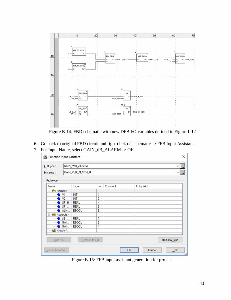
Figure B-14: FBD schematic with new DFB I/O variables defined in Figure 1-12
6. Go back to original FBD circuit and right click on schematic -> FFB Input Assistant
7. For Input Name, select GAIN_dB_ALARM -> OK
Figure B-15: FFB input assistant generation for project.

44
8. Place GAIN_dB_ALARM function block on original schematic -> Build -> Build
changes
Figure B-16: FBD schematic with new DFB placed. Note: you may place it anywhere,
the block demonstrates the ability to compress the circuit into a larger block.
9. Under the “Derived FB Types” in the Project Browser, right-click GAIN_dB_ALARM
and select “Put in Library” -> select Custom Lib -> click Custom FAMILY -> OK -> OK
Figure B-17: Placing the DFB into a custom library saves the circuit for future use in other
projects.

45
Appendix C. Bill of Materials
Table C-1: Bill of Materials

46
Appendix D. Scheduling
Figure D-1: Fall Quarter 2018 Gantt Chart
Figure D-2: Winter Quarter 2019 Gantt Chart
Figure D-3: Spring Quarter 2019 Gantt Chart

47
References:
[1] A. B. Gavali, S. A. Patil and A. R. Koli, "Technology-Based Learning system in
Programmable Logic Controller Education," 2016 IEEE Eighth International Conference on
Technology for Education (T4E), Mumbai, 2016, pp. 264-265.
Description: Ways to teach a PLC course
[2]“ABL8REM24050.” [Online]. Available: https://www.schneider-
electric.us/en/product/ABL8REM24050/regulated-smps---1-or-2-phase---100..240-v-ac---24-v---
5-a/. [Accessed: 08-Jan-2019].
Description: Company page describing who they are and what they do
[3] “About Siemens,” About Siemens - Company - Siemens Global Website. [Online]. Available:
https://www.siemens.com/global/en/home/company/about.html. [Accessed: 19-Oct-2018].
Description: Company page describing what they do and who they are
[4] “About Us,” Discover Schneider Electric . [Online]. Available: https://www.schneider-
electric.us/en/about-us/. [Accessed: 19-Oct-2018].
Description: Company page describing who they are and what they do
[5]“BMXAMI0410.” [Online]. Available: https://www.schneider-
electric.us/en/product/BMXAMI0410/analog-input-module-x80---4-inputs---high-speed/.
[Accessed: 23-Apr-2019].
Description: Company page describing who they are and what they do
[6]“BMXAMO0410.” [Online]. Available: https://www.schneider-
electric.us/en/product/BMXAMO0410/isolated-analog-output-module-x80---4-outputs/.
[Accessed: 25-Jan-2019].
Description: Product page
[7]“BMXCPS3500.” [Online]. Available: https://www.schneider-
electric.us/en/product/BMXCPS3500/power-supply-module-x80---100..240-v-ac---36-w/.
[Accessed: 25-Mar-2019].
Description: Product page
[8]“BMXDDI1602.” [Online]. Available: https://www.schneider-
electric.us/en/product/BMXDDI1602/discrete-input-module-x80---16-inputs---24-v-dc-positive/.
[Accessed: 16-Apr-2019].
Description: Product page
[9]“BMXDRA0805.” [Online]. Available: https://www.schneider-
electric.us/en/product/BMXDRA0805/discrete-output-module-x80---8-outputs---relay---24..240-
v-ac/. [Accessed: 28-Mar-2019].
Description: Product page
48
[10] “Course Description,” Course -- Catalog -- CSU, Chico. [Online]. Available:
http://catalog.csuchico.edu/viewer/course/display.aspx?cycle=11&subject=SMFG&number=386
. [Accessed: 19-Oct-2018].
Description: Description of PLC related course at Chico State
[11] “DIN Rail Enclosures,” Cbus Direct. [Online]. Available:
https://www.cbusdirect.co.uk/cbus-product-range/din-rail-enclosures/. [Accessed: 03-Apr-2019].
Description: Overview of how PLCs work
[12] “Extended Learning,” CSUSB. [Online]. Available: http://bulletin.csusb.edu/extended-
learning/. [Accessed: 19-Oct-2018].
Description: Course description for PLC courses at San Bernardino State
[13] “FDT Group,” About us. [Online]. Available: https://fdtgroup.org/about/fdt-group/.
[Accessed: 19-Oct-2018].
Description: International standard used by Automation industries
[14] “Fresno State,” Industrial Technology. [Online]. Available:
http://www.fresnostate.edu/catalog/subjects/industrial-technology/_source/index.html#courses.
[Accessed: 19-Oct-2018].
Description: Course description for PLC topics are Fresno State
[15]“HMIS5T.” [Online]. Available: https://www.schneider-electric.us/en/product/HMIS5T/stu-
rear-module---dark-grey---width-118-mm---depth-40.1-mm/. [Accessed: 23-Apr-2019].
Description: Product page
[16]“HMIS85.” [Online]. Available: https://www.schneider-
electric.us/en/product/HMIS85/5in7-small-touchscreen-display-front-module-backlight-led-
color-tft-lcd/. [Accessed: 15-Mar-2019].
Description: Product page
[17] “Is Digitization and IoT a New Thing? Not if you come from Industrial Automation,”
Schneider Electric Blog, 16-May-2018. [Online]. Available:
https://blog.schneider-electric.com/machine-and-process-management/2018/01/03/digitization-
iot-new-thing-not-come-industrial-automation/. [Accessed: 19-Oct-2018].
Description: Picture of creator of the first PLC
[18] “Modicon M580 - ePac Controller - Ethernet Programmable Automation controller & Safety
PLC,” Standard environment - Modicon M580 - ePac Controller - Ethernet Programmable Au.
[Online].Available: https://www.schneider-electric.com/en/product-range/62098-modicon-m580-
--epac-controller---ethernet-programmable-automation-controller-&-safety-plc/?parent-category-
id=3900&parent-subcategory-id=3950. [Accessed: 19-Oct-2018].
Description: Product page for PLC donated to Cal Poly

49
[19] P. Pratumsuwan and W. Pongaen, "An embedded PLC development for teaching in
mechatronics education," 2011 6th IEEE Conference on Industrial Electronics and Applications,
Beijing, 2011, pp. 1477-1481.
Description: PLC course description/requirements
[20] “Professional Development,” PLC and Soft Logic Controllers. [Online]. Available:
http://extension.fullerton.edu/ProfessionalDevelopment/Course/13093/1. [Accessed: 19-Oct-
2018].
Description: Description of PLC course at Fullerton State
[21]“P584040.” [Online]. Available: https://www.schneider-
electric.us/en/product/BMEP584040/processor-module-m580---level-4---remote/. [Accessed: 08-
Apr-2019].
Description: Product page
[22] “PLC Hardware,” PLC Hardware - Industrial Automation & Network Equipment. [Online].
Available: https://www.plchardware.com/Products/SM-PPX;505-6504.aspx. [Accessed: 03-Apr-
2019].
Description: PLC Hardware Vendor
[23]“TCSESU053FN0.” [Online]. Available: https://www.schneider-
electric.us/en/product/TCSESU053FN0/ethernet-tcp-ip-switch---connexium---5-ports-for-
copper/. [Accessed: 03-Apr-2019].
Description: Product page
[24]“Tyrone Goose neck Tablet Stand,” Amazon. [Online]. Available:
https://www.amazon.com/Tryone-Gooseneck-Nintendo-Samsung-Overall/dp/B01AUQ33LG.
[Accessed: 23-May-2019].
Description: HMI stand
[25] “Technavio Announces Top Five Vendors in the Global Micro PLC Market from 2016 to
2020,” 02-May-2016. [Online]. Available:
https://www.businesswire.com/news/home/20160502005493/en/Technavio-Announces-Top-
Vendors-Global-Micro-PLC. [Accessed: 19-Oct-2018].
Description: The five major market leaders in PLC analysis
[26] “The Types of PLCs,” Techwalla. [Online]. Available:
https://www.techwalla.com/articles/the-types-of-plcs. [Accessed: 19-Oct-2018].
Description: General overview of PLCs and how they work
[27] “What is a PLC?,” AMCI : Advanced Micro Controls Inc :: What is a PLC? [Online].
Available:
https://www.amci.com/industrial-automation-resources/plc-automation-tutorials/what-plc/.
[Accessed: 19-Oct-2018].
Description: Analysis of how PLCs work and operation

50
[28] “What is PLC? Programmable Logic Controller,” Unitronics. [Online]. Available:
https://unitronicsplc.com/what-is-plc-programmable-logic-controller/. [Accessed: 19-Oct-2018].
Description: Overview of how PLCs work