index kemet - tantalum chip capacitors kemet’s family of solid tantalum chip capacitors is...
TRANSCRIPT
INDEX KEMET®
KEMET Electronics Corporation, P.O. Box 5928, Greenville, S.C. 29606, (864) 963-6300 3
SOLID TANTALUM CHIP CAPACITORSPAGE
GENERAL PERFORMANCE CHARACTERISTICS..................................................................................................4-14T491 SERIES — INDUSTRIAL GRADE .................................................................................................................15-18T492 SERIES — CWR11 STYLE PER MIL-PRF-55365/8.....................................................................................19-20T494 SERIES — LOW ESR, INDUSTRIAL GRADE ...............................................................................................21-23T495 SERIES — LOW ESR, SURGE ROBUST .....................................................................................................24-26T496 SERIES — FAIL-SAFE WITH BUILT-IN FUSE .............................................................................................27-28T510 SERIES — ULTRA-LOW ESR ......................................................................................................................29-31
POLYMER TANTALUM CHIP CAPACITORSPAGE
GENERAL PERFORMANCE CHARACTERISTICS................................................................................................32-37T520 SERIES — KO-CAP POLYMER ...................................................................................................................38-39
CERAMIC CHIP CAPACITORSPAGE
GENERAL PERFORMANCE CHARACTERISTICS................................................................................................40-45CERAMIC CHIP-STANDARD ................................................................................................................................46-50LAND DIMENSIONS ...................................................................................................................................................50CERAMIC CAPACITOR ARRAY............................................................................................................................51-52MIL-PRF-55681 ESTABLISHED RELIABILITY ......................................................................................................53-57MIL-PRF-55681 TAPE AND REEL QUANTITIES ........................................................................................................57
Mil-PRF-123 and GR900 high-reliability ceramic chips are also available. Refer to KEMET Catalog F-3054 fordetailed information.
TANTALUM & CERAMIC CHIP PACKAGINGPAGE
TANTALUM CHIP REEL QUANTITIES........................................................................................................................58CERAMIC CHIP REEL QUANTITIES...........................................................................................................................59EMBOSSED CARRIER TAPE REELING INFORMATION ......................................................................................60-61PUNCHED CARRIER TAPE (PAPER TAPE) REELING INFORMATION .....................................................................62BULK CASSETTE PACKAGING .................................................................................................................................63CERAMIC CHIP MARKING.........................................................................................................................................63
NOTICEAlthough the information in this catalog has been careful-ly checked for accuracy, and is believed to be correctand current, no warranty, either express or implied, ismade as to either its applicability to, or its compatibilitywith, specific requirements; nor does KEMET ElectronicsCorporation assume any responsibilty for correctness ofthis information, nor for damages consequent to its use.All design characteristics, specifications, tolerances, andthe like are subject to change without notice.
NOTICEAny capacitor misapplied may fail and there by damageother circuit components. Please refer to applicationnotes and recommendations in this catalog for a com-plete description of capacitor characteristics.
UL®
RE
GISTERED FIR
M
KE
ME
TEl
ectronics Corporation
ISO9001 A1168
ISO 9001 RegistrationThe quality managementsystem for manufacture of
solid tantalum chips forsurface mount applications
has satisfied therequirements of ISO 9001.
ISO 9001 RegistrationThe quality management
system for the manufactureof commercial ceramic chips
for surface mountapplications has satisfied therequirements of ISO 9001.
UL®
RE
GISTERED FIR
M
KE
ME
TEl
ectronics Corporation
ISO9001 A1685
Refer to F3235 for Aluminum Organic PolymerSurface Mount Products Available.
This catalog will contain the aluminum AO-CAPseries in the next revision.

TANTALUM CHIP CAPACITORSKEMET®
KEMET’s family of solid tantalum chip capacitors isdesigned and manufactured with the demandingrequirements of surface mount technology in mind.
These devices extend the advantages of solid tanta-lum technology to today’s surface mount circuit appli-cations. Complementing multilayer ceramic chip conve-nience with capacitance ratings through1000 µF, tantalum chip capacitors permit circuitdesign-ers to take full advantage of the benefits of surfacemount technology.T491 Series — Industrial
The leading choice in today’s surface mount designsis the KEMET T491 Series. This product meets orexceeds the requirements of EIA standard 535BAAC.The physical outline and dimensions of this series con-form to this global standard.
Four low profile case sizes have been added to theT491 family. The S/3216-12 and T/3528-12 case sizeshave a maximum height of 1.2 mm. The U/6032-15 sizehas a maximum height of 1.5 mm, and the V/7343-20has a maximum height of 2.0 mm.
This product was designed specifically for today’shighly automated surface mount processes and equip-ment. This series uses the same proven solid tantalumKEMET technology acclaimed and respected through-out the world. Added to this is the latest in materials,processes and automation which result in a componentunsurpassed worldwide in total performance and value.
The standard solder-coated terminations provideexcellent wetting characteristics and compatibility withtoday’s surface mount solder systems. Gold-plated ter-minations are also available for use with conductiveepoxy attachment processes. The symmetrical termina-tions offer total compliancy to provide the thermal andmechanical stress relief required in today’s technology.Lead frame attachments to the tantalum pellet are madevia a microprocessor-controlled welding operation, anda high temperature silver epoxy adhesive system.
Standard packaging of these devices is tape andreel in accordance with EIA 481-1. This system providesperfect compatibility with all tape-fed placement units.T492 Series — Military
KEMET is approved to MIL-PRF-55365/8 (CWR11),Weibull failure rate “D” level or 0.001% failures per1,000 hours. This CWR11 product — designated asKEMET’s T492 Series — is a precision-moldeddevice, with compliant leadframe terminations andindelible laser marking. This is the military version ofthe global IEC/EIA standard represented by KEMET’s T491 Series.Tape and reeling per EIA 481-1is standard.T494 Series — Low ESR, Industrial Grade
The T494 is a low ESR series that is available in all thesame case sizes and CV ratings as the popular T491series. The T494 offers low ESR performance with theeconomy of an industrial grade device. This series istargeted for output filtering and other applications thatmay benefit from improved efficiency due to low ESR.T495 Series — Low ESR, Surge Robust
The low ESR, surge robust T495 series is an impor-tant member of KEMET’s tantalum chip family.Designed primarily for output filtering in switch-modepower supplies and DC-to-DC converters, the standardCV T495 values are also an excellent choice for bat-tery-to-ground input filter applications.
This series builds upon proven technology used forindustrial grade tantalum chip capacitors to offer sever-al important advantages: very low ESR, high ripple cur-rent capability, excellent capacitance stability, plusimproved ability to withstand high inrush currents.These benefits are achieved through a combination ofproprietary design, material, and process parameters,as well as high-stress, low impedance electrical condi-tioning performed prior to screening. Capacitance val-ues range from 4.7µF to 470µF, in voltage ratings from6 to 50.T496 Series — Fused
KEMET also offers a “fail-safe” fused solid tantalumchip capacitor. The built-in fuse element providesexcellent protection from damaging short circuit condi-tions in applications where high fault currents exist.Protection from costly circuit damage due to reversedinstallation is offered with this device. Package sizesinclude the EIA standard 3528-12, 6032-15, 7343-31,and 7343-43 case size. Capacitance values range from0.15 µF to 470.0 µF, in voltage ratings from 6 to 50.Standard capacitance tolerances include ±20% and±10%. Tape and reeling per EIA 481-1 is standard.T510 Series — Ultra–Low ESR
The ultra-low ESR T510 Series is a breakthrough insolid tantalum capacitor technology. KEMET’s T510Series offers the industry’s lowest ESR in the popularEIA 7343-43 case size. The ultra-low ESR and high rip-ple current capability make the T510 an ideal choice forSMPS filtering and power decoupling of today’s highspeed microprocessors.
KEMET has developed an innovative constructionplatform that incorporates multiple capacitor elements,in parallel, inside a single package. This unique assem-bly, combined with KEMET’s superior processing tech-nology, provides the best combination of high CV, lowESR, and small size in a user friendly, molded, surfacemount package.
T520 SERIES — KO-CAP Polymer TantalumKEMET’s newest tantalum chip product line is
T520 Series KEMET Organic - KO - Capacitor. TheKO-CAP is a Tantalum capacitor, with Ta anode andTa2O5 dielectric. However, a conductive, organic,polymer replaces the MnO2 as the cathode plate ofthe capacitor. This results in very low ESR andimproved cap retention at high frequency. The KO-CAP also exhibits a benign failure mode, which elimi-nates the ignition failures that can occur in standardMnO2 Tantalum types. Note also that KO-CAPs maybe operated at voltages up to 80% of rated voltagewith equivalent or better reliability than standard tan-talums operated at 50% of rated voltage.
The new T520 series captures the best features ofmultilayer ceramic caps (low ESR and high frequencycap retention), aluminum electrolytics (benign failuremode), and proven solid tantalum technology (volu-metric effficiency, surface mount capability, and nowearout mechanism). The KO-CAP can reduce com-ponent counts, eliminate through-hole assembly byreplacing cumbersome leaded aluminum capacitors,and offer a more cost effective solution to high-costhigh-cap ceramic capacitors. These benefits allowthe designer to save both board space and money.See pages 32-39 for complete details.
PRODUCT DESCRIPTION
KEMET Electronics Corporation, P.O. Box 5928, Greenville, S.C. 29606, (864) 963-63004

SOLID TANTALUM CHIP CAPACITORS
95% RH, referred to the standard 50% RH. Theamount of change is dependent upon size (capaci-tance and voltage rating, ie: CV product); smallsizes might change no more than ±5%.Equilibrium at such extremes is seldom attained byplastic-cased capacitors, and the change incapacitance is consequently less. The rate ofresponse to humidity changes increases withincreasing temperature. Dissipation factor andESR also increase with increasing RH.
DC leakage current may rise upon exposure to acombination of high temperature and high humidi-ty, but is normally restored by voltage conditioningunder standard conditions. The increase will begreater than that experienced under temperatureinfluence alone because of conduction throughabsorbed water.
Tantalum chips may be affected by absorption ofwater on external insulating surfaces.The waterfilm may also attract a layer of dust from the air,increasing the effect. The most sensitive parame-ter is leakage current.
4. Capacitance• 0.1 µF to 1000 µFRefer to part number tables for available capaci-tance ratings and tolerances by series.
Capacitance is measured at 120 Hz, up to 1.0volt rms maximum and up to 2.5 volts DC maximum, at+25°C.DC bias causes only a small reduction in capaci-tance, up to about 2% when full rated voltage is applied.DC bias is not commonly used at room temperature, butis more commonly used at elevated temperatures.Capacitance decreases with increasing frequency.
FIGURE 1 Typical Effect of Frequency upon Capacitance
Capacitance increases with increasing temperature.
FIGURE 2 Typical Effect of Temperature upon Capacitance
IntroductionKEMET solid tantalum capacitors are identified bythe initial “T,” followed by a unique “Series” num-ber; for example, T491, T492, etc. Each Seriesdenotes a general physical form and type ofencapsulation, as well as limits on dimensions andcertain electrical characteristics under standardconditions of 25°C, 50% relative humidity, and oneatmosphere pressure. Specific requirements areset forth in the respective Product Series in thiscatalog. All series are 100% screened for leakage,capacitance, dissipation factor, and ESR. AllSeries are inspected to electrical limits using aminimum .1% AQL sampling plan, according tothe Military Standard MIL-STD-105, even after100% testing. This sampling plan, to the best ofKEMET Electronics’ knowledge, meets or exceedsthe generally accepted industry standard for simi-lar products. KEMET capacitors may also be sup-plied, with prior agreement, to meet specificationswith requirements differing from those of KEMET cat-alogs.
ELECTRICAL1. General Application Class
Solid tantalum capacitors are usually applied incircuits where the AC component is small com-pared to the DC component. Typical uses knownto KEMET Electronics include blocking, by-pass-ing, decoupling, and filtering. They are also used intiming circuits. If two of these polar capacitors areconnected “back-to-back” (i.e., negative-to-nega-tive or positive-to-positive), the pair may be usedin AC applications (as a non-polar device).
2. Operating Temperature Range• –55 °C to +125 °CVoltage derating is specified in Section 5.Performance characteristics over this temperaturerange are presented within the following sections.
3. Non-Operating Temperature Range• –55°C to +125°CTantalum capacitors do not lose capacitance fromthe “de-forming” effect as do liquid-electrolyticcapacitors. Storage at high temperature maycause a small, temporary increase in leakage cur-rent (measured under standard conditions), but theoriginal value is usually restored within a few min-utes after application of rated voltage.
Tantalum chips are not hermetically sealed, there-fore they do exhibit reversible changes in parame-ters with respect to relative humidity (RH).Capacitance increases with increasing humidity.The limiting change, reached upon establishmentof equilibrium with the environment, is approxi-mately -5% to +12% over the range from 25% to
COMPONENT PERFORMANCE CHARACTERISTICS
Reference 1.0at 120 Hz
100 1k 10k
1.0
0.9
Frequency—Hertz
Mu
ltip
lier
of
120
Hz
Cap
acit
ance
+20%
+10%
0
-10%
-20%
-80 -60 -40 -20 0 +20 +60+40 +80 +100 +120
Operating Temperature—C
Per
cen
t C
han
ge
in +
25C
Cap
acit
ance
Val
ue
KEMET Electronics Corporation, P.O. Box 5928, Greenville, S.C. 29606, (864) 963-6300 5
So
lid T
anta
lum
Su
rfac
e M
ou
nt
KEMET®

conditions, including the sum of peak AC ripple,DC bias and any transients.
Surge voltage tests are performed at +25°C,+85°C and +125°C with the applicable surge volt-age. The surge voltage is applied for 1000 cyclesof 30 seconds at voltage through a 33 ohm seriesresistor and 30 seconds off voltage with thecapacitor discharged through a 33 ohm resistor.Upon completing the test, the capacitors areallowed to stabilize at room temperature. Capaci-tance, DCL and DF are then tested:
a. Capacitance — within ± 5% of initial valueb. DC Leakage — within initial limitc. Dissipation Factor — within initial limit
7. Reverse Voltage and Polarity
TABLE 3 Reverse Voltage Ratings
Temperature Permissible Reverse Voltage+25°C 15% of Rated Voltage+85°C 5% of Rated Voltage+125°C 1% of Rated Voltage
Solid tantalum capacitors are polarized devicesand may be permanently damaged or destroyed ifconnected with the wrong polarity. The positiveterminal is identified on the capacitor body by astripe and a beveled edge. A small degree of tran-sient reverse voltage is permissible for short peri-ods per Table 3. The capacitors should not beoperated continuously in reverse mode, even with-in these limits.
8. DC Leakage Current (DCL)Refer to part number tables for maximum leakagecurrent limits.
DC leakage current is the current that, after a one-to five-minute charging period, flows through acapacitor when voltage is applied. Leakage ismeasured at +25°C with full rated DC voltageapplied to the capacitor through a 1000 ohm resis-tor in series with the capacitor.
DC leakage current increases with increasing tem-perature.
TABLE 4 Leakage Limit Multipliers at SpecifiedTemperatures (ref: 25°C limits)
Ambient Temperature
–55°C +85°C +125°CN/A 10X 12X
TABLE 1 Maximum Capacitance Changewith Temperature (ref: 25°C)
Ambient Temperature–55°C +85°C +125°C
–10% +10% *+12% or +15%
*+12% is standard. +15% applies to certain extendedCV values as noted in part number tables.
5. Working DC Voltage (WVDC)• 3 to 50 voltsRefer to part number tables for available voltageratings by series.
These voltages are the maximum recommendedpeak DC operating voltages from –55°C to+85°C for continuous duty. These voltages arederated linearly above +85°C to 2/3 rated voltagefor operation at +125°C (See Figure 3).
FIGURE 3 Working DC Voltage Change with Temperature
6. Surge Voltage
TABLE 2 Surge Voltage Ratingsat +25°C, +85°C & +125°C
RatedWorking Surge Derated
Volts Voltage DC Surge@ +25°C @ +25°C Volts Voltage& +85°C & +85°C @ +125°C @ +125°C
3 4 2 2.44 5.2 2.7 3.26 8 4 5
10 13 7 816 20 10 1220 26 13 1625 33 17 2035 46 23 2850 65 33 40
Surge voltage is the maximum voltage to whichthe capacitor can be subjected under transient
SOLID TANTALUM CHIP CAPACITORS
100%
80%
60%
40%
20%
-60
Operating Temperature—C
Per
cen
t C
han
ge
in
Wo
rkin
g D
C V
olt
age
-40 -20 0 +20 +40 +60 +80 +100 +120 +140
KEMET Electronics Corporation, P.O. Box 5928, Greenville, S.C. 29606, (864) 963-63006
KEMET®
COMPONENT PERFORMANCE CHARACTERISTICS (con’t.)

SOLID TANTALUM CHIP CAPACITORS
COMPONENT PERFORMANCE CHARACTERISTICS (con’t.)
KEMET Electronics Corporation, P.O. Box 5928, Greenville, S.C. 29606, (864) 963-6300 7
So
lid T
anta
lum
Su
rfac
e M
ou
nt
KEMET®
FIGURE 4 Typical Effect of Temperature uponDC Leakage Current
DC leakage current decreases with decreasingapplied voltage.
FIGURE 5 Typical Effect of Applied Voltage on DC Leakage Current.
9. Dissipation Factor (DF)Refer to part number tables for maximum DFlimits.
Dissipation factor is measured at 120 Hz, up to1.0 volt rms maximum, and up to 2.0 volts DCmaximum at +25°C. The application of DC biascauses a small reduction in DF, about 0.2% whenfull rated voltage is applied. DF increases withincreasing frequency.
Frequency — Hertz
FIGURE 6 Typical Effect of Frequency upon Dissipation Factor
Dissipation factor is a very useful low frequency(120 Hz) measurement of the resistive componentof a capacitor. It is the ratio of the equivalent seriesresistance (ESR) to the capacitive reactance, (XC)and is usually expressed as a percentage. It isdirectly proportional to both capacitance and fre-quency. Dissipation factor loses its importance athigher frequencies, (above about 1 kHz), whereimpedance (Z) and equivalent series resistance(ESR) are the normal parameters of concern.DF = R = 2 fCR DF = Dissipation Factor
XC R = Equivalent SeriesResistance (Ohms)
XC = Capacitive Reactance(Ohms)
f = Frequency (Hertz)C = Series Capacitance
(Farads)
DF is also referred to as tan or “loss tangent.”The “Quality Factor,” “Q,” is the reciprocal of DF.DF increases with temperature above +25°C andmay also increase at lower temperatures.Unfortunately, one general limit for DF cannot bespecified for all capacitance/voltage combinations,nor can response to temperature be simply stated.DC bias is not commonly used at room tempera-ture, but is more commonly used at elevated tem-peratures.
10. Equivalent Series Resistance (ESR) andImpedance (Z)Equivalent Series Resistance (ESR) is the pre-ferred high-frequency statement of the resistanceunavoidably appearing in these capacitors. ESRis not a pure resistance, and it decreases withincreasing frequency.Total impedance of the capacitor is the vectorsum of capacitive reactance (XC) and ESR, belowresonance; above resonance total impedance isthe vector sum of inductive reactance (XL) andESR.
Mu
ltip
lier
of
DC
Lea
kag
e C
urr
ent
10.0
1.0
0.1
Operating Temperature—C
-60 -40 -20 0 +20 +40 +60 +80 +100 +125
Reference 1.0at + 25°C
Mul
tiplie
r of
DC
Lea
kage
Cur
rent
Percentage of Rated Voltage
0 10 20 30 40 50 60 70 80 90 100 110
1.0
0.1
0.01
0.001
Mu
ltip
lier
of
120
Hz
D.F
.
100 1k 10k
20.0
10.0
5.0
1.0
Reference1.0 at 120 Hz

SOLID TANTALUM CHIP CAPACITORSKEMET®
KEMET Electronics Corporation, P.O. Box 5928, Greenville, S.C. 29606, (864) 963-6300
RS — Represents the actual ohmic series resis-tance in series with the capacitance. Lead wiresand capacitor electrodes are contributing sources.
RL — Capacitor Leakage Resistance. Typically itcan reach 50,000 megohms in a tantalum capaci-tor. It can exceed 1012 ohms in monolithic ceram-ics and in film capacitors.
Rd — The dielectric loss contributed by dielectricabsorption and molecular polarization. It becomesvery significant in high frequency measurementsand applications. Its value varies with frequency.
Cd — The inherent dielectric absorption of thesolid tantalum capacitor which typically equates to1-2% of the applied voltage.
As frequency increases, XC continues to decreaseaccording to its equation above. There is unavoid-able inductance as well as resistance in all capaci-tors, and at some point in frequency, the reac-tance ceases to be capacitive and becomesinductive. This frequency is called the self-reso-nant point. In solid tantalum capacitors, the reso-nance is damped by the ESR, and a smooth,rather than abrupt, transition from capacitive toinductive reactance follows.
Typical ESR/Z frequency response curves areshown in Figures 9a and 9b. These curves are for selected ratings and represent typical T491Series performance. Maximum limits for 100 kHzESR are listed in the part number tables for each series. Note that the T494 Series offers lowESR and the T495 Series is specially designedfor very low ESR performance. Refer to pages 21and 24 for more information. See also KEMET’sNewest Tantalum Chip family, the T510 Series,which offers the industry’s lowest ESR ratings.See page 29.
8
COMPONENT PERFORMANCE CHARACTERISTICS (con’t.)
1000.0
10k
Frequency - Hertz
Z a
nd E
SR
- O
HM
S
100.0
10.0
1.0
0.1
0.01100 1k 100k 1M 10M
R
R
6.8µF / 35V
.33µF / 35V
1.0µF / 35V
R
Z
Z
Z
FIGURE 7a Total Impedance of the Capacitor Below Resonance
FIGURE 7b Total Impedance of the Capacitor AboveResonance
To understand the many elements of a capaci-tor, see Figure 8.
XC = 1 ohm2fC
where:f = frequency, HertzC = capacitance, Farad
XL = 2fL
where:f = frequency, HertzL = inductance, Henries
A capacitor is a complex impedance consisting ofmany series and parallel elements, each addingto the complexity of the measurement system.
L — Represents lead wire and constructioninductance. In most instances (especially in solidtantalum and monolithic ceramic capacitors) it isinsignificant at the basic measurement frequen-cies of 120 and 1000 Hz.
FIGURE 8 The Real Capacitor
L RS C
RL
Cd Rd
FIGURE 9a ESR & Impedance (Z) vs Frequency

11. AC Power Dissipation
Power dissipation is a function of capacitor sizeand materials. Maximum power ratings have beenestablished for all case sizes to prevent overheat-ing. In actual use, the capacitor’s ability to dissi-pate the heat generated at any given power levelmay be affected by a variety of circuit factors.These include board density, pad size, heat sinksand air circulation.
TABLE 5 Tantalum Chip Power Dissipation Ratings
Case Code Maximum Power DissipationKEMET EIA Watts @ +25°C
R 2012-12 .025S 3216-12 .060T 3528-12 .070U 6032-15 .090V 7343-20 .125A 3216-18 .075B 3528-21 .085C 6032-28 .110D 7343-31 .150X 7343-43 .165E 7260-38 .200
T510X 7343-43 .270T510E 7260-38 .285
12. AC OperationPermissible AC ripple voltage and current arerelated to equivalent series resistance (ESR) andpower dissipation capability.
Permissible AC ripple voltage which may beapplied is limited by three criteria:
a. The positive peak AC voltage plus the DCbias voltage, if any, must not exceed the DCvoltage rating of the capacitor.
b. The negative peak AC voltage, in combinationwith the bias voltage, if any, must not exceedthe permissible reverse voltage ratings pre-sented in Table 3.
c. The power dissipated in the ESR of the capa- citor must not exceed the appropriate valuespecified in Table 5.
Actual power dissipated may be calculated fromthe following:P = l2 RSubstituting I = E
Zwhere:I = rms ripple current (amperes)E = rms ripple voltage (volts)P = power (watts)Z = impedance at specified frequency (ohms)R = equivalent series resistance at specified
frequency (ohms)Using P max from Table 5, maximum allowablerms ripple current or voltage may be determinedas follows:I (max) = P max/R E (max) = Z P max/RThese values should be derated at elevated tem-peratures as follows:
Temperature Derating Factor85C .9
125C .4
ENVIRONMENTAL13. Temperature StabilityTABLE 6 Temperature Stability Limits
Step Leakage DissipationNo. Temp. Capacitance Current Factor
1 +25C within specified within original within originaltolerance limit limit
2 -55C within ± 10% N/A within originalof initial value limit**
3 +25C within ± 5% within original within originalof initial value limit limit
4 + 85C within ± 10% within 10X within originalof initial value original limit limit
5 +125C *within ± 12%or within 12X within original15% of initial original limit limitvalue
6 +25C within ± 5% within original within originalof initial value limit limit
*+12% is standard. +15% applies to certain extended CV valuesas noted in part number table.**within 1.5x initial limit for extended cv values.
SOLID TANTALUM CHIP CAPACITORS KEMET®
P = E2RZ2
,
So
lid T
anta
lum
Su
rfac
e M
ou
nt
1000.0
10k
Frequency - Hertz
Z a
nd E
SR
- O
HM
S
100.0
10.0
1.0
0.1
0.01100 1k 100k 1M 10M
2.2µF / 16V
22µF / 16V
68µF / 16V
Z
Z
R
R
R
Z
KEMET Electronics Corporation, P.O. Box 5928, Greenville, S.C. 29606, (864) 963-6300 9
FIGURE 9b ESR & Impedance (z) vs Frequency
ESR and Z are also affected by temperature. At100 kHz, ESR decreases with increasing temper-ature. The amount of change is influenced by thesize of the capacitor and is generally more pro-nounced on smaller ratings.
FIGURE 10 Typical Effect of Temperature on 100 kHz ESR
COMPONENT PERFORMANCE CHARACTERISTICS (con’t.)
10
1
0.1-50
Temperature - Degrees Centigrade-25 0 25 50 75 100 125
Multiplier of 100kHz ESR

SOLID TANTALUM CHIP CAPACITORSKEMET®
COMPONENT PERFORMANCE CHARACTERISTICS (con’t.)
KEMET Electronics Corporation, P.O. Box 5928, Greenville, S.C. 29606, (864) 963-630010
Mounted capacitors withstand extreme temperaturetesting at a succession of continuous steps at+25°C, -55°C, +25°C, +85°C, +125°C, +25°C, in theorder stated. Capacitors shall be brought to thermalstability at each test temperature. Capacitance, DFand DCL are measured at each test temperatureexcept that DCL is not measured at -55°C. DC biasof 2.0± 0.5 is recommended for the capacitanceand D F requirements.
14. Thermal Shock• Mil-Std-202, Method 107, Condition BMinimum temperature -55°C, mounted
Post Test Performance:
a. Capacitance — within ±5% of initial value
b. DC Leakage — within initial limit
c. Dissipation Factor — within initial limit
15. Moisture Resistance• Mil-Std-202, Method 106Steps 7a and 7b excluded, rated voltage,42 cycles, mounted
Post Test Performance:
a. Capacitance — within ±10% of initial value
b. DC Leakage — within initial limit
c. Dissipation Factor — within initial limit
16. Electrostatic Discharge (ESD)• Human Body Model
2,000 ±50 volts, 1,500 ±5% ohms, 40 nano-second pulse each polarity, 1 pulse eachpolarity, 5 seconds between pulses, +25C.
• Charged Device Model200 ± 5 volts, 0 ohms, 40 nanosecondpulse, each polarity, 9 pulses each polarity,5 seconds between pulses, +25C.
Product subjected to above test conditiondemonstrate no sensitivity to electrostaticdischarge.
Post Test Performance:
a. Capacitance — within ± 5% of initial value
b. DC Leakage — within initial limit
c. Dissipation Factor — within initial limit
17. Long Term StabilityWithin the general class of electrolytic capacitors,solid tantalum capacitors offer unusual stability ofthe three important parameters: capacitance, dis-sipation factor and leakage current. These solid-state devices are not subject to the effects of electrolysis, deforming or drying-out associatedwith liquid-electrolyte capacitors.
When stabilized for measurement at standard conditions, capacitance will typically change lessthan ±3% during a 10,000 hour life test +85°C.
The same comparative change has beenobserved in shelf tests at +25°C extending for50,000 hours. (Some of this change may stemfrom instrument or fixture error.)
Dissipation factor exhibits no typical trend. Datafrom 10,000 hour life test at +85°C show that ini-tial limits (at standard conditions) are not exceededat the conclusion of these tests.
Leakage current is more variable than capaci-tance or DF; in fact, leakage current typicallyexhibits a logarithmic dependence in severalrespects. Military Specifications permit leakagecurrent (measured at standard conditions) to riseby a factor of four over 10,000 hour life tests.Typical behavior shows a lower rate of change,which may be negative or positive. Initial leakagecurrents are frequently so low (less than 0.1nanoampere in the smallest CV capacitors, toabout 10 microampere in the largest CV types)that changes of several orders of magnitude haveno discernable effect on the usual circuit designs.
18. Failure ModeCapacitor failure may be induced by exceedingthe rated conditions of forward DC voltage,reverse DC voltage, surge current, power dissipa-tion, or temperature. As with any practical device,these capacitors also possess an inherent,although low, failure rate when operated withinthe rated condition.
The dominant failure mode is by short-circuit.Minor parametric drifts are of no consequence incircuits suitable for solid tantalum capacitors.Catastrophic failure occurs as an avalanche in DCleakage current over a short (millisecond) timespan. The failed capacitor, while called “short-cir-cuited”, may exhibit a DC resistance of 10 to 104
ohm.
If a failed capacitor is in an unprotected low-impedance circuit, continued flow of currentthrough the capacitor may obviously producesevere overheating. The over-heated capacitormay damage the circuit board or nearby compo-nents. Protection against such occurrence isobtained by current-limiting devices or fuses pro-vided by the circuit design. KEMET’s T496 seriesoffers a built-in fuse to convert the normal shortcircuit failure mode to an open circuit.
Fortunately, the inherent failure rate of KEMETsolid tantalum capacitors is low, and this failurerate may be further improved by circuit design.Statistical failure rates are provided for militarycapacitors. Relating circuit conditions to failurerate is aided by the guides in the section following.

SOLID TANTALUM CHIP CAPACITORS
Ope
ratin
g Te
mpe
ratu
re-D
egre
es C
elsi
us
App
lied
Vol
tage
Rat
io, V
Connect the temperature andapplied voltage ratio ofinterest with a straight edge.The multiplier of failure rate isgiven at the intersection ofthis line with the model scale.
Given T1 & V1 Read FailureRate Multiplier F1Given T, & F2Read Reguired Voltage V2Given F3 & V3Read Allowable Temp T3
120
125
110
100
90
60
85
70
80
50
40
30
25
85°CRating
125°CRating
0.67
1.2
1.1
1.0
0.9
0.8
0.7
0.6
0.5
0.4
0.3
0.2
0.1VT
Fai
lure
Rat
e M
ultip
lier,
F10-1
1.0
102
103
101
10-2
10-3
10-4
10-5
10-6
10-7
10-8
F
size. Inherent failure rate is roughly proportionalto CV1.6, where C is capacitance and V is ratedvoltage. The effect becomes particularly notice-able above 50-volt ratings. Additionally, thosecapacitors identified as “Extended Range” havehigher inherent failure rates and should be speci-fied with caution. It is possible to lose more viahigher inherent failure rate than is gained by volt-age derating. KEMET typically recommends 50%derating, especially in low impedance circuits.
The relationships shown are particularly usefulwhen the failure rate has been statistically deter-mined for a given group of capacitors. The T492Series is qualified under U.S. military specificationMIL-PRF-55365. Failure rates as low as0.001%/Khr are available for all capacitance/volt-age values in given groups under this test pro-gram. The specifications and their accompanyingQualified Products Lists should be consulted fordetails.
For Series not covered by military specifications,an internal sampling program is operated byKEMET Quality Assurance. The confidence levelchosen for reporting the data is 60%. However,the cost of sampling each batch produced is over-whelmingly prohibitive, and no claim is made con-cerning knowledge of failure rate for any particularlot shipped. It is demonstrated that average failurerate for all commercial Series is between .1 and1%/Khr at standard conditions and 60% confi-dence after 2,000 hours testing, +85°C, and ratedvoltage and ≤ 1 ohm total series resistance.
KEMET Electronics Corporation, P.O. Box 5928, Greenville, S.C. 29606, (864) 963-6300 11
So
lid T
anta
lum
Su
rfac
e M
ou
nt
KEMET®
COMPONENT PERFORMANCE CHARACTERISTICS (con’t.)
FIGURE 11 Reliability Nomograph
RELIABILITY19. Reliability Prediction
Solid tantalum capacitors exhibit no degradationfailure mode during shelf storage and show a constantly decreasing failure rate (i.e., absenceof wearout mechanism) during life tests. This fail-ure rate is dependent upon three important appli-cation conditions; DC voltage, temperature, andcircuit impedance. Estimates of these respectiveeffects are provided by the Reliability Nomograph(Figure 11) and the Circuit Impedance ReliabilityFactor Table (Table 7) following. The nomographrelates failure rate to voltage and temperaturewhile the table relates failure rate to impedance.These estimates apply to steady-state DC condi-tions, and they assume usage within all otherrated conditions.
Standard conditions, which produce a unity fail-ure rate factor are rated voltage, +85°C, and 0.1ohm-per-volt circuit impedance. While voltageand temperature are straightforward, there issometimes difficulty in determining impedance.What is required is the circuit impedance seen bythe capacitor. If several capacitors are connectedin parallel, the impedance seen by each is low-ered by the source of energy stored in the othercapacitors. Energy is similarly stored in seriesinductors.
Failure rate is conventionally expressed in units ofpercent per thousand hours. As a sample cal-culation, suppose a particular batch of capacitorshas a failure rate of 0.5% / Khr under standardconditions. What would be the predicted failurerate at 0.7 times rated voltage, 60°C and 0.8Ω/V? The nomograph gives a factor of 7 x 10⁻⁴
and the table gives a factor of 0.3.
The failure rate estimate is then:0.5 x 7 x 10-4 x 0.3 = 1.05 x 10⁻⁴, or 0.0001%/Khr
TABLE 7 Circuit Impedance Reliability Factors
Circuit Impedance Failure Rate Improvement(ohms/volt) (multiplying factors)
0.1 1.00.2 .80.4 .60.6 .40.8 .31.0 .22.0 .1
3 or greater .07
Voltage “de-rating” is a common and usefulapproach to improved reliability. It can be pur-sued too far, however, when it leads to installa-tion of higher voltage capacitors of much larger
KEMET Electronics Corporation, P.O. Box 5928, Greenville, S.C. 29606, (864) 963-6300
SOLID TANTALUM CHIP CAPACITORS
12
KEMET®
COMPONENT PERFORMANCE CHARACTERISTICS (con’t.)
20. Surge CurrentAll conventional reliability testing is conductedunder steady-state DC voltage. Experience indi-cates that AC ripple, within the limits prescribed,has little effect on failure rate. Heavy surge cur-rents are possible in some applications, howev-er. Circuit impedance may be very low (below therecommended 0.1 ohm/volt) or there may be dri-ving inductance to cause voltage “ringing.” Surgecurrent may appear during turn-on of equipment,for example. Failure rate under current-surgeconditions may not be predictable from conven-tional life test data.Capacitors are capable of withstanding a 4 ±1second charge of rated voltage (±2%) through atotal circuit resistance (excluding the capacitor) of1 ±0.2 ohms at +25°C, followed by a 4 ±1 seconddischarge to a voltage below 1% of the rated volt-age. This cycle is repeated consecutively three(3) times. Post test performance:
a. Capacitance — within ±5% of initial valueb. DC Leakage — within initial limitc. Dissipation Factor — within initial limit
100% production surge current testing is per-formed on all Tantalum Chip series for case sizesC, D, E, X, U, V. The total test circuit resistanceis ≤ 0.5 ohms. The applied voltage is 75% ofrated voltage for all series except the T495 andT510 which are surged at 100% of rated voltage.Four surge cycles are applied. Parts not capableof surviving this test are removed at subsequentelectrical screening.
21. Storage Life Test• 2,000 hours, +125 C, Unbiased, MountedPost Test Performance:a. Capacitance — within ±10% of initial valueb. DC Leakage — within initial limitc. Dissipation Factor — within initial limitd. Physical — no degradation of function
22. Standard Life Test• 2,000 hours, +85 C, Rated Voltage, MountedPost Test Performance:a. Capacitance — within ±10% of initial valueb. DC Leakage — within 125% of initial limitc. Dissipation Factor — within initial limitd. Physical — no degradation of function
23. High Temperature Life Test• 2,000 hours, +125 C, 2/3 Rated Voltage,
MountedPost Test Performance:a. Capacitance — within ±10% of initial valueb. DC Leakage — within 125% of initial limitc. Dissipation Factor — within initial limitd. Physical — no degradation of function
MECHANICAL
24. Resistance to Solvents• Mil-Std-202, Method 215Post Test Performance:a. Capacitance — within ±5% of initial valueb. DC Leakage — within initial limitc. Dissipation Factor -— within initial limitd. Physical — no degradation of case, termi-
nals or marking.
25. Fungus• Mil-Std-810, Method 508
26. Flammability• UL94 VO Classification
Encapsulant materials meet thisclassification.
27. Resistance to Soldering Heat• Wave Solder
+260 ±5 C, 10 Seconds• Infrared Reflow
+230 ±5 C, 30 Seconds• Vapor Phase Reflow
+215 ±5 C, 2 minutesPost Test Performance:a. Capacitance — within ±5% of Initial Valueb. DC Leakage — within Initial Limitc. Dissipation Factor — within Initial Limit
28. Solderability• Mil-Std-202, Method 208• ANSI/J-STD-002, Test BApplies to Solder and Tin Coated terminationsonly. Does not apply to optional gold-plated ter-minations.
29. Vibration• Mil-Std-202, Method 204, Condition D,
10 Hz to 2,000 Hz, 20G PeakPost Test Performance:a. Capacitance — within ± 5% of initial valueb. DC Leakage — within initial limitc. Dissipation Factor — within initial limit
30. Shock• Mil-Std-202, Method 213, Condition I,
100 G PeakPost Test Performance:a. Capacitance — within ±5% of initial valueb. DC Leakage — within initial limitc. Dissipation Factor — within initial limit
31. Terminal Strength• Pull Force
• One Pound (454 grams), 30 Seconds

• Shear ForceTable 8 Maximum Shear Loads
Case Code Maximum Shear LoadsKEMET EIA Kilograms Pounds
R 2012-12 2.4 5.3S 3216-12 3.2 7.0T 3528-12 3.6 8.0U 6032-15 4.5 10.0V 7343-20 5.0 11.0A 3216-18 3.2 7.0B 3528-21 3.6 8.0C 6032-28 4.5 10.0D 7343-31 5.0 11.0X 7343-43 5.0 11.0E 7260-38 5.0 11.0
SOLID TANTALUM CHIP CAPACITORS
a gold termination finish is available, at additionalcost, on the T491, T494 and T495 Series only.Thegold finish is not recommended for solder attachment.
For Pb-free soldering processes, we offer a 100%reflowed tin (Sn) termination finish.
34. Recommended Mounting Pad GeometriesProper mounting pad geometries are essentialfor successful solder connections. These dimen-sions are highly process sensitive and should bedesigned to maximize the integrity of the solderjoint, and to minimize component rework due tounacceptable solder joints.
Figure 12 illustrates pad geometry. Tables 9 &10 provide recommended pad dimensions forboth wave and reflow soldering techniques.These dimensions are intended to be a startingpoint for circuit board designers, tobe fine tuned, if necessary, based upon the pecu-liarities of the soldering process and/or circuitboard design.
Contact KEMET for Engineering Bulletin NumberF-2100 entitled “Surface Mount Mounting Pad Dimensions and Considerations” for furtherdetails on this subject.
KEMET Electronics Corporation, P.O. Box 5928, Greenville, S.C. 29606, (864) 963-6300 13
So
lid T
anta
lum
Su
rfac
e M
ou
nt
KEMET®
COMPONENT PERFORMANCE CHARACTERISTICS (con’t.)
4 lb. (1.8 Kg)
Post Test Performance:a. Capacitance — within ±5% of initial valueb. DC Leakage — within initial limitc. Dissipation Factor — within initial limit
APPLICATIONS32. Handling
Automatic handling of encapsulated componentsis enhanced by the molded case which providescompatibility with all types of high speed pick andplace equipment. Manual handling of thesedevices presents no unique problems. Careshould be taken with your fingers, however, toavoid touching the solder-coated terminations asbody oils, acids and salts will degrade the sol-derability of these terminations. Finger cotsshould be used whenever manually handling allsolderable surfaces.
33. Termination CoatingThe standard finish coating for all molded seriesis 90/10 Sn/Pb solder (Tin/Lead-solder coated).
For conductive adhesive attachment processes,
• Tensile Force• Four Pounds (1.8 kilograms), 60 Seconds
X
C
G
ZY
Figure 12
Gridplacementcourtyard
R/2012-12A/3216-18, S/3216-12B/3528-21, T/3528-12C/6032-28, U/6032-15D/7343-31, V/7343-20, X/7343-43E/7260-38
3.904.705.007.608.908.90
0.800.801.102.503.803.80
1.801.502.502.502.704.40
1.551.951.952.552.552.55
2.352.753.055.056.356.35
KEMET/EIA Size CodeZ G X
Y(ref)
C(ref)
Table 9 – Land Pattern Dimensions for Reflow Solder
R/2012-12A/3216-18, S/3216-12B/3528-21, T/3528-12C/6032-28, U/6032-15D/7343-31, V/7343-20, X/7343-43E/7260-38
4.305.105.408.009.709.70
0.800.801.102.503.803.80
1.261.101.801.802.704.40
1.752.152.152.752.952.95
2.552.953.255.256.756.75
KEMET/EIA Size CodeZ G X
Y(ref)
C(ref)
Pad Dimensions - mm
Table 10 – Land Pattern Dimensions for Wave Solder
Pad Dimensions - mm

SOLID TANTALUM CHIP CAPACITORS
260
240
220
210
20 40 60 80 100 120
Time Second
Tem
pera
ture
°C
280
KEMET Electronics Corporation, P.O. Box 5928, Greenville, S.C. 29606, (864) 963-630014
KEMET®
35. SolderingKEMET’s families of surface mount tantalumcapacitors are compatible with wave (single ordual) soldering and IR or vapor phase reflowtechniques. Solder-coated terminations haveexcellent wetting characteristics for high integritysolder fillets. Preheating of these components isrecommended to avoid extreme thermal stress.The maximum recommended preheat rate is 2°Cper second. Figure 13 represents recommendedmaximum solder temperature / time combinationsfor these devices.
Note that although the X/7343-43 case size canwithstand wave soldering, the tall profile (4.3mmmaximum) dictates care in wave process devel-opment.
COMPONENT PERFORMANCE CHARACTERISTICS (con’t.)
FIGURE 13 Time/Temperature Soldering Profile
Hand-soldering should be performed with caredue to the difficulty in process control. If per-formed, care should be taken to avoid contact ofthe soldering iron to the molded case. The ironshould be used to heat the solder pad, applyingsolder between the pad and the termination, untilreflow occurs. The iron should be removed.“Wiping” the edges of a chip and heating the topsurface is not recommended.
During typical reflow operations a slight darken-ing of the gold-colored epoxy may be observed.
This slight darkening is normal and is not harmfulto the product. Marking permanency is not affect-ed by this change.
36. WashingStandard washing techniques and solvents arecompatible with all KEMET surface mount tanta-lum capacitors. Solvents such as Freon TMC andTMS, Trichlorethane, methylene chloride, prelete,and isopropyl alcohol are not harmful to thesecomponents.
If ultrasonic agitation is utilized in the cleaningprocess, care should be taken to minimize ener-gy levels and exposure times to avoid damage tothe terminations.
KEMET tantalum chips are also compatible withnewer aqueous and semi-aqueous processes.
37. EncapsulationsUnder normal circumstances, potting or encap-sulation of KEMET tantalum chips is not required.
38. Storage EnvironmentTantalum chip capacitors should be stored innormal working environments. While the chipsthemselves are quite robust in other environ-ments, solderability will be degraded by expo-sure to high temperatures, high humidity, corro-sive atmospheres, and long term storage. Inaddition, packaging materials will be degradedby high temperature – reels may soften or warp,and tape peel force may increase. KEMET rec-ommends that maximum storage temperaturenot exceed 40 degrees C, and maximum storagehumidity not exceed 60% relative humidity. Inaddition, temperature fluctuations should beminimized to avoid condensation on the parts,and atmospheres should be free of chlorine andsulfur bearing compounds. For optimized solder-ability, chip stock should be used promptly,preferably within 1.5 years of receipt.

Notes: 1. Metric dimensions govern. 2. (Ref) - Dimensions provided for reference only. 3. No dimensions provided for B, P or R because low profile cases do not have a bevel or a notch.
CASE SIZE COMPONENT
KEMET
R
S
T
U
V
EIA
2012-12
3216-12
3528-12
6032-15
7343-20
L
2.0 ± 0.2(.079 ± .008)
3.2 ± 0.2(.126 ± .008)
3.5 ± 0.2(.138 ± .008)
6.0 ± 0.3(.236 ± .012)
7.3 ± 0.3(.287 ± .012)
W
1.3 ± 0.2(.051 ± .008)
1.6 ± 0.2(.063 ± .008)
2.8 ± 0.2(.110 ± .008)
3.2 ± 0.3)(.126 ± .012)
4.3 ± 0.3(.169 ± .012)
H Max.
1.2(.047)
1.2(.047)
1.2(.047)
1.5(0.059)
2.0(0.079)
0.3(.012)
0.3(.012)
0.3(.012)
0.5(0.020)
1.1(0.043)
K Min.
0.9(.035)
1.2(.047)
2.2(.087)
2.2(.087)
2.4(.094)
F ± 0.1
0.5(.020)
0.8(.031)
0.8(.031)
1.3(.051)
1.3(.051)
S ± 0.3
0.05(.002)0.05
(.002)0.05
(.002)0.05
(.002)0.05
(.002)
X(Ref)
T(Ref)
0.13(.005)0.13
(.005)0.13
(.005)0.13
(.005)0.13
(.005)
A(Min)
0.8(.031)
0.8(.031)
1.1(.043)
2.5(.098)
3.8(.150)
G(Ref)
0.5(.020)
1.1(.043)
1.8(.071)
2.8(.110)
3.5(.138)
E(Ref)
0.8(.031)
1.3(.051)
2.2(.087)
2.4(.094)
3.5(.138)
Case SizeA, B, C, D, E, R, S, T, U, V, X
M - ± 20%K - ±10%
*Part number example: T491B105M035AS (14 digits - no spaces)
M105491 A035T B S*
TantalumSeriesT491 - Precision Molded
Capacitance Picofarad CodeFirst two digits represent significant figures.Third digit specifies number of zeros to follow.
Lead Material
Failure Rate
Voltage
Capacitance Tolerance
A - Not Applicable
S - Standard Solder -Coated (90% Sn/10% Pb)G - Gold Plated (A, B, C, D, X only)T - 100% Tin (Sn) Plated and Reflowed
KEMET Electronics Corporation, P.O. Box 5928, Greenville, S.C. 29606, (864) 963-6300
SOLID TANTALUM CHIP CAPACITORST491 SERIES - Precision Molded Chip
CAPACITOR OUTLINE DRAWING
15
So
lid T
anta
lum
Su
rfac
e M
ou
nt
KEMET®
0.10 ± 0.10(.004 ± .004)0.10 ± 0.10
(.004 ± .004)0.10 ± 0.10
(.004 ± .004)0.10 ± 0.10
(.004 ± .004)0.10 ± 0.10
(.004 ± .004)0.10 ± 0.10
(.004 ± .004)
KEMET EIA L* W* H* X(Ref)
P(Ref)
R(Ref)
T(Ref)
A(Min)
G(Ref)
E(Ref)
A
B
C
D
X
E
3216-18
3528-21
6032-28
7343-31
7343-43
7260-38
3.2 ± 0.2(.126 ± .008)
3.5 ± 0.2(.138 ± .008)
6.0 ± 0.3(.236 ± .012)
7.3 ± 0.3(.287 ± .012)
7.3 ± 0.3(.287 ± .012)
7.3 ± 0.3(.287 ± .012)
1.6 ±0.2(.063 ±.008)
2.8 ± 0.2(.110 ± .008)
3.2 ± 0.3(.126 ± .012)
4.3 ± 0.3(.169 ± .012)
4.3 ± 0.3(.169 ± .012)
6.0 ± 0.3(.236 ± .012)
1.6 ± 0.2(.063 ± .008)
1.9 ± 0.2(.075 ± .008)
2.5 ± 0.3(.098 ± .012)
2.8 ± 0.3(.110 ± .012)
4.0 ± 0.3(.157 ± .012)
3.6 ± 0.2(.142 ± .008)
1.2(.047)
2.2(.087)
2.2(.087)
2.4(.094)
2.4(.094)
4.1(.161)
0.8(.031)
0.8(.031)
1.3(.051)
1.3(.051)
1.3(.051)
1.3(.051)
0.4(.016)
0.4(.016)
0.5(.020)
0.5(.020)
0.5(.020)
0.5(.020)
0.9(.035)
1.1(.043)
1.4(.055)
1.5(.059)
2.3(.091)
2.3(.091)
0.4(.016)
0.5(.020)
0.9(.035)
0.9(.035)
1.7(.067)
0.9(.035)
0.4(.016)
1.0(.039)
1.0(.039)
1.0(.039)
1.0(.039)
1.0(.039)
0.13(.005)0.13
(.005)0.13
(.005)0.13
(.005)0.13
(.005)0.13
(.005)
0.8(.031)
1.1(.043)
2.5(.098)
3.8(.150)
3.8(.150)
3.8(.150)
1.1(.043)
1.8(.071)
2.8(.110)
3.5(.138)3.5**(.138)
3.5(.138)
1.3(.051)
2.2(.087)
2.4(.094)
3.5(.138)3.5**(.138)
3.5(.138)
CASE SIZE COMPONENT
Notes: 1. Metric dimensions govern. 2. (Ref) - Dimensions provided for reference only. * Mil-C-55365/8 Specified Dimensions ** Round Glue Pad: 2.9 ±0.1mm (0.114" ±0.004") in diameter at KEMET’s option
K* ± 0.20± (.008) S* ± 0.3
± (.012)F* ± 0.1± (.004)
B(Ref)
± 0.15± (.006)
FEATURES• Meets or Exceeds EIA Standard 535BAAC• Taped and Reeled per EIA 481-1• Symmetrical, Compliant Terminations• Optional Gold-plated Terminations• Laser-marked Case• 100% Surge current test on C, D, E, U, V, X sizes
• Capacitance: 0.1 F to 1000 F• Tolerance: ±10%, ±20%• Voltage: 3-50 VDC• Extended Range Values• New Low Profile Case Sizes
STANDARD T491 DIMENSIONSMillimeters (inches)
T491 ORDERING INFORMATION
CATHODE (-) ENDVIEW
W
K
X
ANODE (+) ENDVIEW
R
P
BOTTOM VIEW
A
L
FE
SIDE VIEW
SGS
T
H
B
B
Notch atKEMET'sOption,either end
LOW PROFILE T491 DIMENSIONSMillimeters (inches)

Standard Capacitance Values Extended Capacitance Values
Note that standard values are preferred. Extended values are available for use where size constraints exist. Note that standardvalues demonstrate inherently lower failure rates than extended values, especially in low impedance applications.
104
154
224
334
474
684
105
155
225
335
475
685
106
156
226
336
476
686
107
157
227
337
477
4 6 10 16 20 25 35 504 6 10 16 20 25 35 50
0.10
0.15
0.22
0.33
0.47
0.68
1.0
1.5
2.2
3.3
4.7
6.8
10.0
15.0
22.0
33.0
47.0
68.0
100.0
150.0
220.0
330.0
470.0
Code
0.10
0.15
0.22
0.33
0.47
0.68
1.0
1.5
2.2
3.3
4.7
6.8
10.0
15.0
22.0
33.0
47.0
68.0
100.0
150.0
220.0
330.0
470.0
104
154
224
334
474
684
105
155
225
335
475
685
106
156
226
336
476
686
107
157
227
337
477
A
A
A/B
B/C
D
A
A
A/B
B/C
D
A
A
A/B
B/C
A
A
A/B
B/C
D
A
A/B
B/C
D
D
A
A
A
B
B
C
C
C
D
D
A
A
A
A
B
B
C
C
D
D
A
B
B
B
C
C
C
D
D
D
D
S
T/A
V
D/X
S
T/A
T/A
V/C
C
V/D
D/X
X
S
T/A
T/A
D/X
X
R
A
D
X
C
D
X
A
C
C
V
X
A
A
B
C
C/V
X
A
B
B
C
C
Capacitance Rated Voltage @ +85°CµF Code
Capacitance Rated Voltage @ +85°C3
A
687680.0680.0 687 X
A/B
S/A
S/A B/C
B/CS/A
S/A
S/A
S/A
B/T
µF
C/DA/B/T
A/B/T
A/B/T
A/B/T
C/U X
B/C/U
B/C/U
B/C/U
B/C/U
C/U
X
X
C/U
C/U
C/U
C/U
C/D/V
C/D D/V D/V
X
XC/D D/V
D/V
D/V D
D
X
X
X
V
A
A
R/S
B
BR/S
B D
B U/B C D
T/A U/B U/C D
U/B U/C C
U/B U/C C D
DU/C C
DV/C
V/D
D/VC/D
R/S
B
D
B
CA/B
A/B
1081000.0 1081000.0 E
SOLID TANTALUM CHIP CAPACITORST491 SERIES—Precision Molded Chip
KEMET Electronics Corporation, P.O. Box 5928, Greenville, S.C. 29606, (864) 963-630016
KEMET®
T491 TANTALUM CHIP CAPACITANCE VALUESCase Size by Capacitance and Voltage

SOLID TANTALUM CHIP CAPACITORST491 SERIES - Precision Molded Chip
KEMET®
KEMET Electronics Corporation, P.O. Box 5928, Greenville, S.C. 29606, (864) 963-6300 17
So
lid T
anta
lum
Su
rfac
e M
ou
nt
T491 RATINGS & PART NUMBER REFERENCE
DC DF ESRCapaci- Leakage % @ +25C @ +25Ctance Case KEMET A @ 25C 120 Hz 100 kHzF Size Part Number Max Max Max
3 Volt Rating at +85 C (2 Volt Rating at +125 C)#33.0 *A T491A336(1)003AS 1.0 6.0 4.0
4 Volt Rating at +85 C (2.7 Volt Rating at +125 C)3.3 A T491A335(1)004AS 0.5 6.0 8.04.7 A T491A475(1)004AS 0.5 6.0 8.06.8 A T491A685(1)004AS 0.5 6.0 6.06.8 S T491S685(1)004AS 0.5 6.0 15.0
10.0 B T491B106(1)004AS 0.5 6.0 3.510.0 A T491A106(1)004AS 0.5 6.0 6.0
#10.0 *S T491S106(1)004AS 0.5 6.0 15.0
15.0 B T491B156(1)004AS 0.6 6.0 3.515.0 A T491A156(1)004AS 0.6 6.0 4.0
#15.0 *S T491S156M004AS 0.6 10.0 15.015.0 T T491T156(1)004AS 0.6 6.0 5.0
22.0 C T491C226(1)004AS 0.9 6.0 1.822.0 B T491B226(1)004AS 0.9 6.0 3.5
#22.0 *A T491A226(1)004AS 0.9 6.0 4.0#22.0 *T T491T226(1)004AS 0.9 6.0 5.033.0 C T491C336(1)004AS 1.3 6.0 1.8
33.0 B T491B336(1)004AS 1.3 6.0 3.5#33.0 *A T491A336(1)004AS 1.3 6.0 4.0#33.0 *T T491T336M004AS 1.3 8.0 5.0
33.0 U T491U336(1)004AS 1.3 6.0 1.8
47.0 C T491C476(1)004AS 1.9 6.0 1.8
#47.0 *B T491B476(1)004AS 1.9 6.0 3.047.0 U T491U476(1)004AS 1.9 6.0 1.8
68.0 D T491D686(1)004AS 2.7 6.0 0.868.0 C T491C686(1)004AS 2.7 6.0 1.6
#68.0 *B T491B686(1)004AS 2.7 6.0 3.5#68.0 *U T491U686(1)004AS 2.7 6.0 1.8
100.0 D T491D107(1)004AS 4.0 8.0 0.8#100.0 *C T491C107(1)004AS 4.0 8.0 1.2#100.0 *U T491U107(1)004AS 4.0 10.0 1.8150.0 D T491D157(1)004AS 6.0 8.0 0.8
#150.0 *C T491C157(1)004AS 6.0 8.0 1.2150.0 V T491V157(1)004AS 6.0 8.0 0.7
#220.0 *V T491V227(1)004AS 8.8 8.0 0.7#330.0 *D T491D337(1)004AS 13.2 8.0 0.7#330.0 *V T491V337M004AS 13.2 12.0 0.7#470.0 *X T491X477(1)004AS 18.8 8.0 0.5#470.0 *D T491D477(1)004AS 18.8 8.0 0.5
**6 Volt Rating at +85 C (4 Volt Rating at +125 C)2.2 A T491A225(1)006AS 0.5 6.0 8.03.3 A T491A335(1)006AS 0.5 6.0 8.04.7 A T491A475(1)006AS 0.5 6.0 6.04.7 S T491S475(1)006AS 0.5 6.0 15.06.8 B T491B685(1)006AS 0.5 6.0 3.56.8 A T491A685(1)006AS 0.5 6.0 6.0
#6.8 *S T491S685(1)006AS 0.5 6.0 15.010.0 B T491B106(1)006AS 0.6 6.0 3.510.0 A T491A106(1)006AS 0.6 6.0 4.0
#10.0 *S T491S106M006AS 0.6 10.0 15.010.0 T T491T106(1)006AS 0.6 6.0 5.0
9.0 8.0
15.0 C T491C156(1)006AS 0.9 6.0 1.815.0 B T491B156(1)006AS 0.9 6.0 3.5
#15.0 *A T491A156(1)006AS 0.9 6.0 4.0#15.0 *T T491T156(1)006A5 0.9 6.0 5.022.0 C T491C226(1)006AS 1.4 6.0 1.8
22.0 B T491B226(1)006AS 1.4 6.0 3.5#22.0 *A T491A226(1)006AS 1.4 6.0 4.0#22.0 *T T491T226M006AS 1.4 8.0 5.0
22.0 U T491U226(1)006AS 1.4 6.0 1.8
33.0 C T491C336(1)006AS 2.0 6.0 1.8
#33.0 *B T491B336(1)006AS 2.0 6.0 3.033.0 U T491U336(1)006AS 2.0 6.0 1.8
47.0 D T491D476(1)006AS 2.9 6.0 0.847.0 C T491C476(1)006AS 2.9 6.0 1.6
#47.0 *B T491B476(1)006AS 2.9 6.0 3.5#47.0 *U T491U476(1)006AS 2.9 6.0 1.8
68.0 D T491D686(1)006AS 4.1 6.0 0.8#68.0 *C T491C686(1)006AS 4.1 6.0 1.2#68.0 *U T491U686(1)006AS 4.1 10.0 1.8100.0 D T491D107(1)006AS 6.0 8.0 0.8100.0 V T491V107(1)006AS 6.0 8.0 0.7
#100.0 *C T491C107(1)006AS 6.0 8.0 1.2150.0 D T491D157(1)006AS 9.0 8.0 0.7
#150.0 *C T491C157M006AS 1.2#150.0 *V T491V157(1)006AS 9.0 8.0 0.7220.0 X T491X227(1)006AS 13.2 8.0 0.7
#220.0 *D T491D227(1)006AS 13.2 8.0 0.7#220.0 *V T491V227M006AS 13.2 12.0 0.7#330.0 *X T491X337(1)006AS 19.8 8.0 0.5#330.0 *D T491D337(1)006AS 19.8 8.0 0.5#470.0 *X T491X477(1)006AS 28.2 10.0 0.5
DC DF ESRCapaci- Leakage % @ +25C @ +25Ctance Case KEMET A @ 25C 120 Hz 100 kHzF Size Part Number Max Max Max
10 Volt Rating at +85 °C (7 Volt Rating at +125 °C)1.5 A T491A155(1)010AS 0.5 6.0 8.02.2 A T491A225(1)010AS 0.5 6.0 8.03.3 A T491A335(1)010AS 0.5 6.0 6.03.3 S T491S335(1)010AS 0.5 6.0 15.04.7 B T491B475(1)010AS 0.5 6.0 3.54.7 A T491A475(1)010AS 0.5 6.0 6.0
#4.7 *S T491S475(1)010AS 0.5 6.0 15.0
6.8 B T491B685(1)010AS 0.7 6.0 3.56.8 A T491A685(1)010AS 0.7 6.0 6.0
#6.8 *S T491S685M010AS 0.7 10.0 15.06.8 T T491T685(1)010AS 0.7 6.0 5.0
10.0 C T491C106(1)010AS 1.0 6.0 1.810.0 B T491B106(1)010AS 1.0 6.0 3.5
#10.0 *A T491A106(1)010AS 1.0 6.0 4.0#10.0 *T T491T106(1)010AS 1.0 6.0 5.015.0 C T491C156(1)010AS 1.5 6.0 1.8
15.0 B T491B156(1)010AS 1.5 6.0 3.5#15.0 *A T491A156(1)010AS 1.5 8.0 6.0#15.0 *T T491T156M010AS 1.5 8.0 5.0
15.0 U T491U156(1)010AS 1.5 6.0 1.8
22.0 C T491C226(1)010AS 2.2 6.0 1.8
#22.0 *B T491B226(1)010AS 2.2 6.0 3.022.0 U T491U226(1)010AS 2.2 6.0 1.8
33.0 D T491D336(1)010AS 3.3 6.0 0.8
33.0 C T491C336(1)010AS 3.3 6.0 1.6
#33.0 *B T491B336(1)010AS 3.3 6.0 3.5#33.0 *U T491U336(1)010AS 3.3 6.0 1.8
33.0 V T491V336(1)010AS 3.3 6.0 0.7
47.0 D T491D476(1)010AS 4.7 6.0 0.8
#47.0 *C T491C476(1)010AS 4.7 6.0 1.247.0 V T491V476(1)010AS 4.7 6.0 0.7
#47.0 *U T491U476(1)010AS 4.7 10.0 2.268.0 D T491D686(1)010AS 6.8 6.0 0.868.0 V T491V686(1)010AS 6.8 6.0 0.7
#68.0 *C T491C686(1)010AS 6.8 6.0 1.2100.0 D T491D107(1)010AS 10.0 8.0 0.7
#100.0 *C T491C107(1)010AS 10.0 8.0 1.2#100.0 *V T491V107(1)010AS 10.0 8.0 0.7150.0 X T491X157(1)010AS 15.0 8.0 0.7
#150.0 *D T491D157(1)010AS 15.0 8.0 0.7#220.0 *X T491X227(1)010AS 22.0 8.0 0.5#220.0 *D T491D227(1)010AS 22.0 8.0 0.5#330.0 *X T491X337(1)010AS 33.0 10.0 0.5
16 Volt Rating at +85 C (10 Volt Rating at +125 C)1.0 A T491A105(1)016AS 0.5 4.0 10.01.5 A T491A155(1)016AS 0.5 6.0 8.02.2 A T491A225(1)016AS 0.5 6.0 6.02.2 S T491S225(1)016AS 0.5 6.0 15.0
(1) To complete KEMET Part Number, insert M for ±20% tolerance or K for ± 10% tolerance.
#Maximum Capacitance Change @125 C=+15%. (All others =+12%)
C)
3.3 B T491B335(1)016AS 0.5 6.0 3.53.3 A T491A335(1)016AS 0.5 6.0 6.04.7 B T491B475(1)016AS 0.8 6.0 3.54.7 A T491A475(1)016AS 0.8 6.0 6.04.7 T T491T475(1)016AS 0.8 6.0 5.06.8 C T491C685(1)016AS 1.1 6.0 1.9
#6.8 *A T491A685(1)016AS 1.1 6.0 7.06.8 B T491B685(1)016AS 1.1 6.0 3.5
10.0 C T491C106(1)016AS 1.6 6.0 1.8
T491B106(1)016AS10.0 B 1.6 6.0 3.5T491U106(1)016AS10.0 U 1.6 6.0 1.8
15.0 C T491C156(1)016AS 2.4 6.0 1.8
#15.0 *B T491B156(1)016AS 2.4 6.0 3.015.0 U T491U156(1)016AS 2.4 6.0 1.8
22.0 D T491D226(1)016AS 3.6 6.0 0.822.0 C T491C226(1)016AS 3.6 6.0 1.6
#22.0 *B T491B226(1)016AS 3.5 6.0 3.0#22.0 *U T491U226(1)016AS 3.5 10.0 3.0
33.0 D T491D336(1)016AS 5.3 6.0 0.8#33.0 *C T491C336(1)016AS 5.3 6.0 1.2#33.0 *U T491U336(1)016AS 5.3 12.0 3.047.0 D T491D476(1)016AS 7.5 6.0 0.8
#47.0 *C T491C476(1)016AS 7.5 6.0 1.247.0 V T491V476(1)016AS 7.5 6.0 0.7
68.0 *D T491D686(1)016AS 10.9 6.0 0.7100.0 X T491X107(1)016AS 16.0 8.0 0.7
#100.0 *D T491D107(1)016AS 16.0 8.0 0.7#150.0 *X T491X157(1)016AS 24.0 8.0 0.5
20 Volt Rating at +85 C (13 Volt Rating at +1250.68 A T491A684(1)020AS 0.5 4.0 12.01.0 A T491A105(1)020AS 0.5 4.0 10.01.0 S T491S105(1)020AS 0.5 6.0 18.0
Higher voltage ratings, lower ESR, and tighter capacitance tolerance product may be substituted within the same size at KEMET’s option. Voltage substitu-
be marked with the higher voltage rating.*Extended Values **6 Volt product equivalent to 6.3 volt product.
#2.2 *R T491R225M016AS 0.5 8.0 25.0
#4.7 *R T491R475M010AS 0.5 8.0 10.0
#10.0 *R T491R106M006AS 0.6 8.0 10.0
#680.0 *X T491X687M004AS 27.2 12.0 0.5
#10.0 *R T491R106M004AS 0.5 8.0 10.0
tions will
#47.0 *A T491A476M004AS 1.9 12.0 2.5
#1000.0 *E T491E108M004AS 40.0 15.0 0.2
#33.0 *A T491A336M006AS 2.0 12.0 2.5

SOLID TANTALUM CHIP CAPACITORST491 SERIES—Precision Molded Chip
CONSTRUCTIONCAPACITOR MARKINGST491 Series — All Case Sizes
Print Week Code:1st Digit = Year
2nd & 3rd Digits = Week"142" = The 42nd week of 2001
PolarityIndicator (+)
PicofaradCode
KEMETI. D. Symbol
RatedVoltage
2 2 62 0 K
1 4 2aaaaaaaaaaaaNegative
Termination*
Mn02 Coat(First Layer)
Silver Paint(Third Layer)
TantalumWire
Carbon(Second Layer)
Tantalum(Ta2O5)
MoldedCase
Silver AdhesiveWasher
PositiveTermination*
Weld
PolarityStripe (+)
PolarityBevel (+)
*Termination Solder Coating 90 Sn/10Pb
KEMET Electronics Corporation, P.O. Box 5928, Greenville, S.C. 29606, (864) 963-630018
KEMET®
T491 RATINGS & PART NUMBER REFERENCE
(1) To complete KEMET Part Number, insert M for ±20% tolerance or K for ±10% tolerance.
Higher voltage ratings, lower ESR, and tighter capacitance tolerance product may be substituted within the same size at KEMET’s option. Voltage substitu-
will be marked with the higher voltage rating.
DC DF ESRCapaci- Leakage % @ +25C @ +25Ctance Case KEMET A @ 25C 120 Hz 100 kHzF Size Part Number Max Max Max20 Volt Rating at +85 C (13 Volt Rating at +125 C) cont’d1.5 A T491A155(1)020AS 0.5 6.0 8.01.5 S T491S155(1)020AS 0.5 6.0 15.02.2 B T491B225(1)020AS 0.5 6.0 3.52.2 A T491A225(1)020AS 0.5 6.0 7.03.3 B T491B335(1)020AS 0.7 6.0 3.5
#3.3 *A T491A335(1)020AS 0.7 6.0 7.03.3 T T491T335(1)020AS 0.7 6.0 5.04.7 C T491C475(1)020AS 1.0 6.0 2.44.7 B T491B475(1)020AS 1.0 6.0 3.56.8 C T491C685(1)020AS 1.4 6.0 1.9
#6.8 *B T491B685(1)020AS 1.4 6.0 3.56.8 U T491U685(1)020AS 1.4 6.0 1.9
10.0 C T491C106(1)020AS 2.0 6.0 1.8
#10.0 *B T491B106(1)020AS 2.0 6.0 3.010.0 U T491U106(1)020AS 2.0 6.0 1.8
15.0 D T491D156(1)020AS 3.0 6.0 1.015.0 *C T491C156(1)020AS 3.0 6.0 1.722.0 D T491D226(1)020AS 4.4 6.0 0.8
#22.0 *C T491C226(1)020AS 4.4 6.0 1.222.0 V T491V226(1)020AS 4.4 6.0 0.7
33.0 D T491D336(1)020AS 6.6 6.0 0.8
47.0 *D T491D476(1)020AS 9.4 6.0 0.768.0 X T491X686(1)020AS 13.6 6.0 0.7
#68.0 *D T491D686(1)020AS 13.6 8.0 0.7#100.0 *X T491X107(1)020AS 20.0 8.0 0.5
25 Volt Rating at +85 C (17 Volt Rating at +125 C)0.33 A T491A334(1)025AS 0.5 4.0 15.00.47 A T491A474(1)025AS 0.5 4.0 14.00.68 A T491A684(1)025AS 0.5 4.0 10.01.0 B T491B105(1)025AS 0.5 4.0 5.01.0 *A T491A105(1)025AS 0.5 4.0 8.01.5 B T491B155(1)025AS 0.5 6.0 5.01.5 *A T491A155(1)025AS 0.5 6.0 10.02.2 C T491C225(1)025AS 0.6 6.0 3.52.2 B T491B225(1)025AS 0.6 6.0 4.53.3 C T491C335(1)025AS 0.9 6.0 2.53.3 *B T491B335(1)025AS 0.9 6.0 3.54.7 C T491C475(1)025AS 1.2 6.0 2.4
6.8 C T491C685(1)025AS 1.7 6.0 1.910.0 D T491D106(1)025AS 2.5 6.0 1.010.0 *C T491C106(1)025AS 2.5 6.0 1.515.0 D T491D156(1)025AS 3.8 6.0 1.0
#15.0 *C T491C156(1)025AS 3.8 6.0 1.522.0 D T491D226(1)025AS 5.5 6.0 0.822.0 *V T491V226(1)025AS 5.5 6.0 0.733.0 X T491X336(1)025AS 8.3 6.0 0.7
#33.0 *D T491D336(1)025AS 8.3 6.0 0.7#47.0 *X T491X476(1)025AS 11.8 6.0 0.7
DC DF ESRCapaci- Leakage % @ +25C @ +25Ctance Case KEMET A @ 25C 120 Hz 100 kHz
F Size Part Number Max Max Max
35 Volt Rating at +85 C (23 Volt Rating at +125 C)0.10 A T491A104(1)035AS 0.5 4.0 20.00.15 A T491A154(1)035AS 0.5 4.0 19.00.22 A T491A224(1)035AS 0.5 4.0 18.00.33 A T491A334(1)035AS 0.5 4.0 15.00.47 B T491B474(1)035AS 0.5 4.0 8.00.47 A T491A474(1)035AS 0.5 4.0 14.00.68 B T491B684(1)035AS 0.5 4.0 6.50.68 *A T491A684(1)035AS 0.5 4.0 10.01.0 B T491B105(1)035AS 0.5 4.0 5.01.0 *A T491A105(1)035AS 0.5 4.0 10.01.5 C T491C155(1)035AS 0.5 6.0 4.51.5 B T491B155(1)035AS 0.5 6.0 5.02.2 C T491C225(1)035AS 0.8 6.0 3.52.2 *B T491B225(1)035AS 0.8 6.0 4.03.3 C T491C335(1)035AS 1.2 6.0 2.54.7 D T491D475(1)035AS 1.7 6.0 1.54.7 C T491C475(1)035AS 1.7 6.0 2.56.8 D T491D685(1)035AS 2.4 6.0 1.36.8 *C T491C685(1)035AS 2.4 6.0 2.010.0 D T491D106(1)035AS 3.5 6.0 1.0
#10.0 *C T491C106M035AS 3.5 6.0 2.0#10.0 *V T491V106(1)035AS 3.5 6.0 2.015.0 X T491X156(1)035AS 5.3 6.0 0.915.0 *D T491D156(1)035AS 5.3 6.0 0.822.0 X T491X226(1)035AS 7.7 6.0 0.7
#22.0 *D T491D226M035AS 7.7 6.0 0.7#33.0 *X T491X336(1)035AS 11.6 6.0 0.6
50 Volt Rating at +85 C (33 Volt Rating at +125 C)0.10 A T491A104(1)050AS 0.5 4.0 20.00.15 B T491B154(1)050AS 0.5 4.0 16.00.15 *A T491A154(1)050AS 0.5 4.0 19.00.22 B T491B224(1)050AS 0.5 4.0 14.00.33 B T491B334(1)050AS 0.5 4.0 10.00.47 C T491C474(1)050AS 0.5 4.0 8.00.47 *B T491B474(1)050AS 0.5 4.0 9.00.68 C T491C684(1)050AS 0.5 4.0 7.00.68 *B T491B684(1)050AS 0.5 4.0 8.01.0 C T491C105(1)050AS 0.5 4.0 5.5
1.5 D T491D155(1)050AS 0.8 6.0 3.51.5 *C T491C155(1)050AS 0.8 6.0 4.52.2 D T491D225(1)050AS 1.1 6.0 2.52.2 *C T491C225(1)050AS 1.1 6.0 3.53.3 D T491D335(1)050AS 1.7 6.0 2.04.7 D T491D475(1)050AS 2.4 6.0 1.56.8 X T491X685(1)050AS 3.5 6.0 1.0
*Extended Values **6 Volt product equivalent to 6.3 volt product.
#Maximum Capacitance Change @ 125C=+15%. (All others = +12%)
1.0 *V T491V105M050AS 0.5 4.0 6.0
tions
#33.0 *C T491C336M020AS 6.6 6.0 1.2
#4.7 *B T491B475M025AS 1.2 6.0 1.5

SOLID TANTALUM CHIP CAPACITORST492 SERIES—Style CWR11 Per Mil-PRF-55365/8
CASE SIZE COMPONENT
±0.20 ±-0.1 ±0.3 B ±0.15 X P R T A G EKEMET EIA L* W* H* K*
±(.008)F*
±(.004)S*
±(.012) ± (.006) (Ref) (Ref) (Ref) (Ref) (Min) (Ref) (Ref)A 3216-18 3.2 ± 0.2 1.6 ± 0.2 1.6 ± 0.2 0.9 1.2 0.8 0.4 0.10 ± 0.10 0.4 0.4 0.13 0.8 1.1 1.3
(.126 ± .008) (.063 ± .008) (.063 ± .008) (.035) (.047) (.031) (.016) (.004 ± .004) (.016) (.016) (.005) (.031) (.043) (.051)B 3528-21 3.5 ± 0.2 2.8 ± 0.2 1.9 ± 0.2 1.1 2.2 0.8 0.4 0.10 ± 0.10 0.5 1.0 0.13 1.1 1.8 2.2
(.138 ± .008) (.110 ± .008) (.075 ± .008) (.043) (.087) (.031) (.016) (.004 ± .004) (.020) (.039) (.005) (.043) (.071) (.087)C 6032-28 6.0 ± 0.3 3.2 ± 0.3 2.5 ± 0.3 1.4 2.2 1.3 0.5 0.10 ± 0.10 0.9 1.0 0.13 2.5 2.8 2.4
(.236 ± .012) (.126 ± .012) (.098 ± .012) (.055) (.087) (.051) (.020) (.004 ± .004) (.035) (.039) (.005) (.098) (.110) (.094)D 7343-31 7.3 ± 0.3 4.3± 0.3 2.8 ± 0.3 1.5 2.4 1.3 0.5 0.10 ± 0.10 0.9 1.0 0.13 3.8 3.5 3.5
(.287 ± .012) (.169 ± .012) (.110 ± .012) (.059) (.094) (.051) (.020) (.004 ± .004) (.035) (.039) (.005) (.150) (.138) (.138)
KEMET Electronics Corporation, P.O. Box 5928, Greenville, S.C. 29606, (864) 963-6300 19
So
lid T
anta
lum
Su
rfac
e M
ou
nt
KEMET®
• Established reliability military version ofIndustrial Grade T491 series
• Taped and reeled per EIA 481-1• Precision-molded, laser-marked case• Symmetrical, compliant terminations• 100% Surge Current test on C, D sizes
• Qualified to MIL-PRF-55365/8, Style CWR11:– Termination Code H, solder-plated– Weibull failure rate codes B, C and D– Capacitance values and voltages as shown
in following part number table. (ContactKEMET for latest qualification status)
DIMENSIONS – Millimeters (Inches)
105H KCWR11 M B
Style
VoltageD = 6V J = 20VF = 10V K = 25VH = 15V M = 35V
Termination Finish CodeH = Solder Plated
Failure Rate Symbol*
Capacitance Tolerance
(*See Note Below)B (0.1%/1000 hrs.)C (0.01%/1000 hrs.)D (0.001%/1000 hrs.)
M - ± 20%K - ± 10%J - ± 5%
Capacitors, Chip, Fixed,Tantalum,Established Reliability, (encapsulated)
Capacitance Picofarad CodeFirst two digits represent significant figures.
Third digit specifies number of zeros to follow.
T492 SERIES ORDERING INFORMATION — KEMET Part Number
ORDERING INFORMATION — MIL-PRF-55365 Part Number
K105492 B035T B S*
TantalumSeriesT492 - Precision Molded, Style CWR11
Case SizeA, B, C, DCapacitance Picofarad CodeFirst two digits represent significant figures.Third digit specifies number of zeros to follow.
Lead Material
Failure Rate Symbol*
VoltageCapacitance Tolerance
(*See Note Below)B (0.1%/1000 hrs.)C (0.01%/1000 hrs.)D (0.001%/1000 hrs.)
M - ± 20%K - ± 10%J - ± 5%
S - Standard Solder -Coated
* Part Number Example: T492B105K035BS (14 digits - no spaces)
*Note on Failure Rates: Exponential failure rate levels M, P, R and S are inactive for new design per Mil-C-55365.Parts qualified to Weibull failure rate levels are substitutable for exponential failure rate levels.
Notes: 1. Metric dimensions govern.2. (Ref) - Dimensions provided for reference only.
* Mil-C-55365/8 Specified Dimensions
CATHODE (-) ENDVIEW
W
K
X
ANODE (+) ENDVIEW
R
P
BOTTOM VIEW
A
L
FE
SIDE VIEW
SGS
T
H
B
B
Notch atKEMET'sOptionEitherEnd
T492 OUTLINE DRAWINGS
(Ref)
PolarityIndicator (+)
PicofaradCode
KEMETI. D. Symbol
RatedVoltage
1 5 62 0 K
1 1 3
JJanBrand
Print Week Code:1st Digit = Year
2nd & 3rd Digits = Week"113" = The 13th week of 2001
DC DF ESRCapaci- Leakage % @ +25C @ +25Ctance Case KEMET Mil-C-55365/8 A @ +25C 120 Hz 100kHz
F Size Part Number Part Number Max Max Max
6 Volt Rating at +85C (4 Volt Rating at +125C)1.5 A T492A155(1)006(2)S CWR11DH155(1)(2) 0.5 6.0 8.02.2 A T492A225(1)006(2)S CWR11DH225(1)(2) 0.5 6.0 8.03.3 A T492A335(1)006(2)S CWR11DH335(1)(2) 0.5 6.0 8.04.7 B T492B475(1)006(2)S CWR11DH475(1)(2) 0.5 6.0 5.56.8 B T492B685(1)006(2)S CWR11DH685(1)(2) 0.5 6.0 4.5
10.0 B T492B106(1)006(2)S CWR11DH106(1)(2) 0.6 6.0 3.515.0 C T492C156(1)006(2)S CWR11DH156(1)(2) 0.9 6.0 3.022.0 C T492C226(1)006(2)S CWR11DH226(1)(2) 1.4 6.0 2.247.0 D T492D476(1)006(2)S CWR11DH476(1)(2) 2.8 6.0 1.1
10 Volt Rating at +85C (7 Volt Rating at 125C)1.0 A T492A105(1)010(2)S CWR11FH105(1)(2) 0.5 4.0 10.01.5 A T492A155(1)010(2)S CWR11FH155(1)(2) 0.5 6.0 8.02.2 A T492A225(1)010(2)S CWR11FH225(1)(2) 0.5 6.0 8.03.3 B T492B335(1)010(2)S CWR11FH335(1)(2) 0.5 6.0 5.54.7 B T492B475(1)010(2)S CWR11FH475(1)(2) 0.5 6.0 4.56.8 B T492B685(1)010(2)S CWR11FH685(1)(2) 0.7 6.0 3.5
15.0 C T492C156(1)010(2)S CWR11FH156(1)(2) 1.5 6.0 2.533.0 D T492D336(1)010(2)S CWR11FH336(1)(2) 3.3 6.0 1.1
15 Volt Rating at +85C (10 Volt Rating at +125C)0.68 A T492A684(1)015(2)S CWR11HH684(1)(2) 0.5 4.0 12.01.0 A T492A105(1)015(2)S CWR11HH105(1)(2) 0.5 4.0 10.01.5 A T492A155(1)015(2)S CWR11HH155(1)(2) 0.5 6.0 8.02.2 B T492B225(1)015(2)S CWR11HH225(1)(2) 0.5 6.0 5.53.3 B T492B335(1)015(2)S CWR11HH335(1)(2) 0.5 6.0 5.04.7 B T492B475(1)015(2)S CWR11HH475(1)(2) 0.7 6.0 4.0
10.0 C T492C106(1)015(2)S CWR11HH106(1)(2) 1.6 6.0 2.522.0 D T492D226(1)015(2)S CWR11HH226(1)(2) 3.3 6.0 1.1
20 Volt Rating at +85C (13 Volt Rating at +125C)0.47 A T492A474(1)020(2)S CWR11JH474(1)(2) 0.5 4.0 14.00.68 A T492A684(1)020(2)S CWR11JH684(1)(2) 0.5 4.0 12.01.0 A T492A105(1)020(2)S CWR11JH105(1)(2) 0.5 4.0 10.01.5 B T492B155(1)020(2)S CWR11JH155(1)(2) 0.5 6.0 6.02.2 B T492B225(1)020(2)S CWR11JH225(1)(2) 0.5 6.0 5.03.3 B T492B335(1)020(2)S CWR11JH335(1)(2) 0.7 6.0 4.04.7 C T492C475(1)020(2)S CWR11JH475(1)(2) 1.0 6.0 3.06.8 C T492C685(1)020(2)S CWR11JH685(1)(2) 1.4 6.0 2.4
15.0 D T492D156(1)020(2)S CWR11JH156(1)(2) 3.0 6.0 1.125 Volt Rating at +85C (17 Volt Rating at +125C)
0.33 A T492A334(1)025(2)S CWR11KH334(1)(2) 0.5 4.0 15.00.47 A T492A474(1)025(2)S CWR11KH474(1)(2) 0.5 4.0 14.00.68 B T492B684(1)025(2)S CWR11KH684(1)(2) 0.5 4.0 7.51.0 B T492B105(1)025(2)S CWR11KH105(1)(2) 0.5 4.0 6.51.5 B T492B155(1)025(2)S CWR11KH155(1)(2) 0.5 6.0 6.52.2 C T492C225(1)025(2)S CWR11KH225(1)(2) 0.6 6.0 3.53.3 C T492C335(1)025(2)S CWR11KH335(1)(2) 0.9 6.0 3.54.7 C T492C475(1)025(2)S CWR11KH475(1)(2) 1.2 6.0 2.56.8 D T492D685(1)025(2)S CWR11KH685(1)(2) 1.7 6.0 1.4
10.0 D T492D106(1)025(2)S CWR11KH106(1)(2) 2.5 6.0 1.235 Volt Rating at +85C (23 Volt Rating at +125C)
0.10 A T492A104(1)035(2)S CWR11MH104(1)(2) 0.5 4.0 24.00.15 A T492A154(1)035(2)S CWR11MH154(1)(2) 0.5 4.0 21.00.22 A T492A224(1)035(2)S CWR11MH224(1)(2) 0.5 4.0 18.00.33 A T492A334(1)035(2)S CWR11MH334(1)(2) 0.5 4.0 15.00.47 B T492B474(1)035(2)S CWR11MH474(1)(2) 0.5 4.0 10.00.68 B T492B684(1)035(2)S CWR11MH684(1)(2) 0.5 4.0 8.01.0 B T492B105(1)035(2)S CWR11MH105(1)(2) 0.5 4.0 6.51.5 C T492C155(1)035(2)S CWR11MH155(1)(2) 0.5 6.0 4.52.2 C T492C225(1)035(2)S CWR11MH225(1)(2) 0.8 6.0 3.53.3 C T492C335(1)035(2)S CWR11MH335(1)(2) 1.2 6.0 2.54.7 D T492D475(1)035(2)S CWR11MH475(1)(2) 1.7 6.0 1.5
SOLID TANTALUM CHIP CAPACITORST492 SERIES—Style CWR11 Per Mil-PRF-55365/8
KEMET Electronics Corporation, P.O. Box 5928, Greenville, S.C. 29606, (864) 963-630020
KEMET®
CONSTRUCTION
CAPACITOR MARKINGST492 Series — All Case Sizes
To complete Part Numbers:(1) Insert “M” for ±20% tolerance, “K” for ±10% tolerance or “J” for ±5% tolerance.(2) Insert Failure Rate Symbol: B (0.1%/1000 hours), C (0.01%/1000 hours) or
D (0.001%/1000 hours).
Note on Failure Rates:Exponential failure ratelevels M, P, R and S areinactive for new designper MIL-C-55365. Partsqualified to Weibull failurerate levels are substitutablefor exponential failurerate levels.Note: ESR limits are perMil-C-55365/8
T492 (CWR11) RATINGS AND PART NUMBER REFERENCEaaaaaaaaaaaaNegativeTermination*
Mn02 Coat(First Layer)
Silver Paint(Third Layer)
TantalumWire
Carbon(Second Layer)
Tantalum(Ta2O5)
MoldedCase
Silver AdhesiveWasher
PositiveTermination*
Weld
PolarityStripe (+)
PolarityBevel (+)
*Termination Solder Coating 90 Sn/10Pb

Notes: 1. Metric dimensions govern. 2. (Ref) - Dimensions provided for reference only. 3. No dimensions provided for B, P or R because low profile cases do not have a bevel or a notch.
CASE SIZE COMPONENT
KEMET
R
S
T
U
V
EIA
2012-12
3216-12
3528-12
6032-15
7343-20
L
2.0 ± 0.2(.079 ± .008)
3.2 ± 0.2(.126 ± .008)
3.5 ± 0.2(.138 ± .008)
6.0 ± 0.3(.236 ± .012)
7.3 ± 0.3(.287 ± .012)
W
1.3 ± 0.2(.051 ± .008)
1.6 ± 0.2(.063 ± .008)
2.8 ± 0.2(.110 ± .008)
3.2 ± 0.3)(.126 ± .012)
4.3 ± 0.3(.169 ± .012)
H Max.
1.2(.047)
1.2(.047)
1.2(.047)
1.5(0.059)
2.0(0.079)
0.3(.012)
0.3(.012)
0.3(.012)
0.5(0.020)
1.1(0.043)
K Min.
0.9(.035)
1.2(.047)
2.2(.087)
2.2(.087)
2.4(.094)
F ± 0.1
0.5(.020)
0.8(.031)
0.8(.031)
1.3(.051)
1.3(.051)
S ± 0.3
0.05(.002)0.05
(.002)0.05
(.002)0.05
(.002)0.05
(.002)
X(Ref
T(Ref)
0.13(.005)0.13
(.005)0.13
(.005)0.13
(.005)0.13
(.005)
A(Min)
0.8(.031)
0.8(.031)
1.1(.043)
2.5(.098)
3.8(.150)
G(Ref)
0.5(.020)
1.1(.043)
1.8(.071)
2.8(.110)
3.5(.138)
E(Ref)
0.8(.031)
1.3(.051)
2.2(.087)
2.4(.094)
3.5(.138)
0.10 ± 0.10(.004 ± .004)0.10 ± 0.10
(.004 ± .004)0.10 ± 0.10
(.004 ± .004)0.10 ± 0.10
(.004 ± .004)0.10 ± 0.10
(.004 ± .004)0.10 ± 0.10
(.004 ± .004)
KEMET EIA L* W* H* X(Ref)
P(Ref)
R(Ref)
T(Ref)
A(Min)
G(Ref)
E(Ref)
A
B
C
D
X
E
3216-18
3528-21
6032-28
7343-31
7343-43
7260-38
3.2 ± 0.2(.126 ± .008)
3.5 ± 0.2(.138 ± .008)
6.0 ± 0.3(.236 ± .012)
7.3 ± 0.3(.287 ± .012)
7.3 ± 0.3(.287 ± .012)
7.3 ± 0.3(.287 ± .012)
1.6 ±0.2(.063 ±.008)
2.8 ± 0.2(.110 ± .008)
3.2 ± 0.3(.126 ± .012)
4.3 ± 0.3(.169 ± .012)
4.3 ± 0.3(.169 ± .012)
6.0 ± 0.3(.236 ± .012)
1.6 ± 0.2(.063 ± .008)
1.9 ± 0.2(.075 ± .008)
2.5 ± 0.3(.098 ± .012)
2.8 ± 0.3(.110 ± .012)
4.0 ± 0.3(.157 ± .012)
3.6 ± 0.2(.142 ± .008)
1.2(.047)
2.2(.087)
2.2(.087)
2.4(.094)
2.4(.094)
4.1(.161)
0.8(.031)
0.8(.031)
1.3(.051)
1.3(.051)
1.3(.051)
1.3(.051)
0.4(.016)
0.4(.016)
0.5(.020)
0.5(.020)
0.5(.020)
0.5(.020)
0.9(.035)
1.1(.043)
1.4(.055)
1.5(.059)
2.3(.091)
2.3(.091)
0.4(.016)
0.5(.020)
0.9(.035)
0.9(.035)
1.7(.067)
0.9(.035)
0.4(.016)
1.0(.039)
1.0(.039)
1.0(.039)
1.0(.039)
1.0(.039)
0.13(.005)0.13
(.005)0.13
(.005)0.13
(.005)0.13
(.005)0.13
(.005)
0.8(.031)
1.1(.043)
2.5(.098)
3.8(.150)
3.8(.150)
3.8(.150)
1.1(.043)
1.8(.071)
2.8(.110)
3.5(.138)3.5**(.138)
3.5(.138)
1.3(.051)
2.2(.087)
2.4(.094)
3.5(.138)3.5**(.138)
3.5(.138)
CASE SIZE COMPONENT
Notes: 1. Metric dimensions govern. 2. (Ref) - Dimensions provided for reference only. * Mil-C-55365/8 Specified Dimensions ** Round Glue Pad: 2.9 ±0.1mm (0.114" ±0.004") in diameter at KEMET’s option
K* ± 0.20± (.008) S* ± 0.3
± (.012)F* ± 0.1± (.004)
B(Ref)
± 0.15± (.006)
KEMET®
KEMET Electronics Corporation, P.O. Box 5928, Greenville, S.C. 29606, (864) 963-6300 21
So
lid T
anta
lum
Su
rfac
e M
ou
nt
SOLID TANTALUM CHIP CAPACITORST494 SERIES — Low ESR, Industrial Grade
CAPACITOR OUTLINE DRAWING
FEATURES• Low ESR values in EIA 535BAAC sizes• Taped and Reeled per EIA 481-1• Symmetrical, Compliant Terminations• Optional Gold-plated Terminations• Laser-marked Case• 100% Surge Current test on C, D, E, U, V, X sizes
• Capacitance: 0.1 F to 1000 F• Tolerance: ±10%, ±20%• Voltage: 3-50 VDC• Extended Range Values• New Low Profile Case Sizes
STANDARD T494 DIMENSIONSMillimeters (inches)
T494 ORDERING INFORMATION
CATHODE (-) ENDVIEW
W
K
X
ANODE (+) ENDVIEW
R
P
BOTTOM VIEW
A
L
FE
SIDE VIEW
SGS
T
H
B
B
Notch atKEMET'sOption,either end
LOW PROFILE T494 DIMENSIONSMillimeters (inches)
Case SizeA, B, C, D, E, R, S, T, U, V, X
M - ± 20%K - ±10%
*Part number example: T494B105M035AS (14 digits - no spaces)
M105494 A035T B S*
TantalumSeriesT494 - Low ESR, Industrial Grade
Capacitance Picofarad CodeFirst two digits represent significant figures.Third digit specifies number of zeros to follow.
Lead Material
Failure Rate
Voltage
Capacitance Tolerance
A - Not Applicable
S - Standard Solder -Coated (90% Sn/10% Pb)G - Gold Plated (A, B, C, D, X only)T - 100% Tin (Sn) Plated and Reflowed

KEMET Electronics Corporation, P.O. Box 5928, Greenville, S.C. 29606, (864) 963-6300
SOLID TANTALUM CHIP CAPACITORST494 SERIES—Low ESR, Industrial Grade
22
KEMET®
T494 RATINGS & PART NUMBER REFERENCE
Higher voltage ratings, lower ESR, and tighter capacitance tolerance product may be substituted within the same size at KEMET’s option. Voltage substitutions will be marked with the higher voltage rating.*Extended Values **6 Volt product equivalent to 6.3 volt product.
DC DF ESRCapaci- Leakage % @ +25C @ +25Ctance Case KEMET A @ 25C 120 Hz 100 kHz
F Size Part Number Max Max Max
**6 Volt Rating at +85 C (4 Volt Rating at +125 C) cont’d.220.0 X T494X227(1)006AS 13.2 8.0 0.15
#220.0 *D T494D227(1)006AS 13.2 8.0 0.15#220.0 *V T494V227M006AS 13.2 12.0 0.3#330.0 *X T494X337(1)006AS 19.8 8.0 0.15#330.0 *D T494D337(1)006AS 19.8 8.0 0.15#470.0 *X T494X477(1)006AS 28.2 10.0 0.10
10 Volt Rating at +85 C (7 Volt Rating at +125 C)1.5 A T494A155(1)010AS 0.5 6.0 6.02.2 A T494A225(1)010AS 0.5 6.0 6.03.3 A T494A335(1)010AS 0.5 6.0 4.03.3 S T494S335(1)010AS 0.5 6.0 9.04.7 B T494B475(1)010AS 0.5 6.0 1.54.7 A T494A475(1)010AS 0.5 6.0 3.0
#4.7 *S T494S475(1)010AS 0.5 6.0 9.0
6.8 B T494B685(1)010AS 0.7 6.0 1.26.8 A T494A685(1)010AS 0.7 6.0 3.0
#6.8 *S T494S685M010AS 0.7 10.0 9.06.8 T T494T685(1)010AS 0.7 6.0 2.0
10.0 C T494C106(1)010AS 1.0 6.0 0.610.0 B T494B106(1)010AS 1.0 6.0 0.8
#10.0 *A T494A106(1)010AS 1.0 6.0 2.0#10.0 *T T494T106(1)010AS 1.0 6.0 3.515.0 C T494C156(1)010AS 1.5 6.0 0.5
15.0 B T494B156(1)010AS 1.5 6.0 0.7#15.0 *A T494A156(1)010AS 1.5 8.0 4.0#15.0 *T T494T156M010AS 1.5 8.0 3.5
15.0 U T494U156(1)010AS 1.5 6.0 0.8
22.0 C T494C226(1)010AS 2.2 6.0 0.4
#22.0 *B T494B226(1)010AS 2.2 6.0 0.722.0 U T494U226(1)010AS 2.2 6.0 0.8
33.0 D T494D336(1)010AS 3.3 6.0 0.25
33.0 C T494C336(1)010AS 3.3 6.0 0.30
#33.0 *B T494B336(1)010AS 3.3 6.0 2.00#33.0 *U T494U336(1)010AS 3.3 6.0 0.60
33.0 V T494V336(1)010AS 3.3 6.0 0.30
47.0 D T494D476(1)010AS 4.7 6.0 0.22
#47.0 *C T494C476(1)010AS 4.7 6.0 0.3047.0 V T494V476(1)010AS 4.7 6.0 0.30
#47.0 *U T494U476(1)010AS 4.7 10.0 1.2068.0 D T494D686(1)010AS 6.8 6.0 0.20
#68.0 *C T494C686(1)010AS 6.8 6.0 0.3068.0 V T494V686(1)010AS 6.8 6.0 0.30
100.0 D T494D107(1)010AS 10.0 8.0 0.15#100.0 *C T494C107(1)010AS 10.0 8.0 0.30#100.0 *V T494V107(1)010AS 10.0 8.0 0.40150.0 X T494X157(1)010AS 15.0 8.0 0.15
#150.0 *D T494D157(1)010AS 15.0 8.0 0.15#220.0 *X T494X227(1)010AS 22.0 8.0 0.15#220.0 *D T494D227(1)010AS 22.0 8.0 0.15#330.0 X T494X337(1)010AS 33.0 10.0 0.10
16 Volt Rating at +85 C (10 Volt Rating at +125 C)1.0 A T494A105(1)016AS 0.5 4.0 6.01.5 A T494A155(1)016AS 0.5 6.0 6.02.2 A T494A225(1)016AS 0.5 6.0 4.02.2 S T494S225(1)016AS 0.5 6.0 10.0
3.3 B T494B335(1)016AS 0.5 6.0 2.03.3 A T494A335(1)016AS 0.5 6.0 4.04.7 B T494B475(1)016AS 0.8 6.0 1.54.7 A T494A475(1)016AS 0.8 6.0 3.04.7 T T494T475(1)016AS 0.8 6.0 3.06.8 C T494C685(1)016AS 1.1 6.0 0.86.8 B T494B685(1)016AS 1.1 6.0 1.2
#6.8 *A T494A685(1)016AS 1.1 6.0 3.010.0 C T494C106(1)016AS 1.6 6.0 0.6
10.0 B T494B106(1)016AS 1.6 6.0 0.810.0 U T494U106(1)016AS 1.6 6.0 1.0
15.0 C T494C156(1)016AS 2.4 6.0 0.4
#15.0 *B T494B156(1)016AS 2.4 6.0 0.815.0 U T494U156(1)016AS 2.4 6.0 0.8
22.0 D T494D226(1)016AS 3.6 6.0 0.2522.0 C T494C226(1)016AS 3.6 6.0 0.35
#22.0 *B T494B226(1)016AS 3.5 6.0 1.00#22.0 *U T494U226(1)016AS 3.5 10.0 1.80
DC DF ESRCapaci- Leakage % @ +25C @ +25Ctance Case KEMET A @ 25C 120 Hz 100 kHzF Size Part Number Max Max Max
3 Volt Rating at +85 C (2 Volt Rating at +125 C)#33.0 *A T494A336(1)003AS 1.0 6.0 2.0
4 Volt Rating at +85 C (2.7 Volt Rating at +125 C)3.3 A T494A335(1)004AS 0.5 6.0 4.04.7 A T494A475(1)004AS 0.5 6.0 3.56.8 A T494A685(1)004AS 0.5 6.0 3.06.8 S T494S685(1)004AS 0.5 6.0 7.0
10.0 B T494B106(1)004AS 0.5 6.0 1.210.0 A T494A106(1)004AS 0.5 6.0 2.0
#10.0 *S T494S106(1)004AS 0.5 6.0 9.0
15.0 B T494B156(1)004AS 0.6 6.0 1.215.0 A T494A156(1)004AS 0.6 6.0 1.5
#15.0 *S T494S156M004AS 0.6 10.0 9.015.0 T T494T156(1)004AS 0.6 6.0 2.0
22.0 C T494C226(1)004AS 0.9 6.0 0.522.0 B T494B226(1)004AS 0.9 6.0 0.6
#22.0 *A T494A226(1)004AS 0.9 6.0 1.5#22.0 *T T494T226(1)004AS 0.9 6.0 2.533.0 C T494C336(1)004AS 1.3 6.0 0.5
33.0 B T494B336(1)004AS 1.3 6.0 0.5#33.0 *A T494A336(1)004AS 1.3 6.0 3.0#33.0 *T T494T336M004AS 1.3 8.0 3.5
33.0 U T494U336(1)004AS 1.3 6.0 0.6
47.0 C T494C476(1)004AS 1.9 6.0 0.5
#47.0 *B T494B476(1)004AS 1.9 6.0 0.547.0 U T494U476(1)004AS 1.9 6.0 0.6
68.0 D T494D686(1)004AS 2.7 6.0 0.2068.0 C T494C686(1)004AS 2.7 6.0 0.25
#68.0 *B T494B686(1)004AS 2.7 6.0 2.00#68.0 *U T494U686(1)004AS 2.7 6.0 0.60
100.0 D T494D107(1)004AS 4.0 8.0 0.20#100.0 *C T494C107(1)004AS 4.0 8.0 0.20#100.0 *U T494U107(1)004AS 4.0 10.0 1.00150.0 D T494D157(1)004AS 6.0 8.0 0.15150.0 V T494V157(1)004AS 6.0 8.0 0.20
#150.0 *C T494C157(1)004AS 6.0 8.0 0.30#220.0 *V T494V227(1)004AS 8.8 8.0 0.30#330.0 *D T494D337(1)004AS 13.2 8.0 0.15#330.0 *V T494V337M004AS 13.2 12.0 0.30#470.0 *X T494X477(1)004AS 18.8 8.0 0.15#470.0 *D T494D477(1)004AS 18.8 8.0 0.15
**6 Volt Rating at +85 C (4 Volt Rating at +125 C)2.2 A T494A225(1)006AS 0.5 6.0 6.03.3 A T494A335(1)006AS 0.5 6.0 6.04.7 A T494A475(1)006AS 0.5 6.0 3.54.7 S T494S475(1)006AS 0.5 6.0 8.06.8 B T494B685(1)006AS 0.5 6.0 1.26.8 A T494A685(1)006AS 0.5 6.0 2.0
#6.8 *S T494S685(1)006AS 0.5 6.0 9.010.0 B T494B106(1)006AS 0.6 6.0 1.010.0 A T494A106(1)006AS 0.6 6.0 2.0
#10.0 *S T494S106M006AS 0.6 10.0 9.010.0 T T494T106(1)006AS 0.6 6.0 1.2
15.0 C T494C156(1)006AS 0.9 6.0 0.615.0 B T494B156(1)006AS 0.9 6.0 0.7
#15.0 *A T494A156(1)006AS 0.9 6.0 2.0#15.0 *T T494T156(1)006AS 0.9 6.0 2.522.0 C T494C226(1)006AS 1.4 6.0 0.5
22.0 B T494B226(1)006AS 1.4 6.0 0.6#22.0 *A T494A226(1)006AS 1.4 6.0 3.0#22.0 *T T494T226M006AS 1.4 8.0 3.5
22.0 U T494U226(1)006AS 1.4 6.0 0.8
33.0 C T494C336(1)006AS 2.0 6.0 0.3
#33.0 *B T494B336(1)006AS 2.0 6.0 0.633.0 U T494U336(1)006AS 2.0 6.0 0.6
47.0 D T494D476(1)006AS 2.9 6.0 0.2247.0 C T494C476(1)006AS 2.9 6.0 0.25
#47.0 *B T494B476(1)006AS 2.9 6.0 2.00#47.0 *U T494U476(1)006AS 2.9 6.0 0.60
68.0 D T494D686(1)006AS 4.1 6.0 0.20#68.0 *C T494C686(1)006AS 4.1 6.0 0.20#68.0 *U T494U686(1)006AS 4.1 10.0 1.00100.0 D T494D107(1)006AS 6.0 8.0 0.15100.0 V T494V107(1)006AS 6.0 8.0 0.20
#100.0 *C T494C107(1)006AS 6.0 8.0 0.30150.0 D T494D157(1)006AS 9.0 8.0 0.15
#150.0 *C T494C157M006AS 9.0 8.0 0.30#150.0 *V T494V157(1)006AS 9.0 8.0 0.30(1) To complete KEMET Part Number, insert M for ±20% tolerance or K for ± 10%
tolerance.
#2.2 *R T494R225M016AS 0.5 8.0 20.0
#4.7 *R T494R475M010AS 0.5 8.0 8.0
#10.0 *R T494R106M006AS 0.6 8.0 6.0
#680.0 *X T494X687M004AS 27.2 12.0 0.10
#10.0 *R T494R106M004AS 0.5 8.0 6.0
#47.0 *A T494A476M004AS 1.9 12.0 2.0
#1000.0 *E T494E108M004AS 40.0 15.0 0.08
#33.0 *A T494A336M006AS 2.0 12.0 2.0

Print Week Code:1st Digit = Year
2nd & 3rd Digits = Week"127" = The 27th week of 2001
PolarityIndicator (+)(• Denotes T494)
PicofaradCode
KEMETI. D. Symbol
RatedVoltage
1 0 71 0 K
1 2 7
CONSTRUCTIONCAPACITOR MARKINGST494 Series — All Case SizesaaaaaaaaaaaaNegative
Termination*
Mn02 Coat(First Layer)
Silver Paint(Third Layer)
TantalumWire
Carbon(Second Layer)
Tantalum(Ta2O5)
MoldedCase
Silver AdhesiveWasher
PositiveTermination*
Weld
PolarityStripe (+)
PolarityBevel (+)
*Termination Solder Coating 90 Sn/10Pb
KEMET Electronics Corporation, P.O. Box 5928, Greenville, S.C. 29606, (864) 963-6300 23
So
lid T
anta
lum
Su
rfac
e M
ou
nt
KEMET®SOLID TANTALUM CHIP CAPACITORS
T494 SERIES—Low ESR, Industrial Grade
T494 RATINGS & PART NUMBER REFERENCEDC DF ESR
Capaci- Leakage % @ +25C @ +25Ctance Case KEMET A @ 25C 120 Hz 100 kHz
F Size Part Number Max Max Max25 Volt Rating at +85 C (17 Volt Rating at +125 C) cont'd
4.7 C T494C475(1)025AS 1.2 6.0 0.6
6.8 C T494C685(1)025AS 1.7 6.0 0.610.0 D T494D106(1)025AS 2.5 6.0 0.410.0 *C T494C106(1)025AS 2.5 6.0 0.615.0 D T494D156(1)025AS 3.8 6.0 0.35
#15.0 *C T494C156(1)025AS 3.8 6.0 0.9022.0 D T494D226(1)025AS 5.5 6.0 0.3022.0 *V T494V226(1)025AS 5.5 6.0 0.5033.0 X T494X336(1)025AS 8.3 6.0 0.30
#33.0 *D T494D336(1)025AS 8.3 6.0 0.40#47.0 *X T494X476(1)025AS 11.8 6.0 0.30
35 Volt Rating at +85 C (23 Volt Rating at +125 C)0.10 A T494A104(1)035AS 0.5 4.0 10.00.15 A T494A154(1)035AS 0.5 4.0 6.00.22 A T494A224(1)035AS 0.5 4.0 6.00.33 A T494A334(1)035AS 0.5 4.0 6.00.47 B T494B474(1)035AS 0.5 4.0 2.50.47 A T494A474(1)035AS 0.5 4.0 4.00.68 B T494B684(1)035AS 0.5 4.0 2.50.68 *A T494A684(1)035AS 0.5 4.0 6.01.0 B T494B105(1)035AS 0.5 4.0 2.01.0 *A T494A105(1)035AS 0.5 4.0 6.01.5 C T494C155(1)035AS 0.5 6.0 2.51.5 B T494B155(1)035AS 0.5 6.0 3.02.2 C T494C225(1)035AS 0.8 6.0 1.52.2 *B T494B225(1)035AS 0.8 6.0 2.53.3 C T494C335(1)035AS 1.2 6.0 0.84.7 D T494D475(1)035AS 1.7 6.0 0.74.7 C T494C475(1)035AS 1.7 6.0 0.76.8 D T494D685(1)035AS 2.4 6.0 0.56.8 *C T494C685(1)035AS 2.4 6.0 0.9
10.0 D T494D106(1)035AS 3.5 6.0 0.4#10.0 *C T494C106M035AS 3.5 6.0 1.2#10.0 *V T494V106(1)035AS 3.5 6.0 0.815.0 X T494X156(1)035AS 5.3 6.0 0.3015.0 *D T494D156(1)035AS 5.3 6.0 0.3522.0 X T494X226(1)035AS 7.7 6.0 0.30#22.0 *D T494D226M035AS 7.7 6.0 0.40
#33.0 *X T494X336(1)035AS 11.6 6.0 0.3050 Volt Rating at +85 C (33 Volt Rating at +125 C)
0.10 A T494A104(1)050AS 0.5 4.0 10.00.15 B T494B154(1)050AS 0.5 4.0 10.00.15 *A T494A154(1)050AS 0.5 4.0 10.00.22 B T494B224(1)050AS 0.5 4.0 10.00.33 B T494B334(1)050AS 0.5 4.0 2.50.47 C T494C474(1)050AS 0.5 4.0 1.80.47 *B T494B474(1)050AS 0.5 4.0 2.00.68 C T494C684(1)050AS 0.5 4.0 1.60.68 *B T494B684(1)050AS 0.5 4.0 3.01.0 C T494C105(1)050AS 0.5 4.0 1.6
1.5 D T494D155(1)050AS 0.8 6.0 1.01.5 *C T494C155(1)050AS 0.8 6.0 1.52.2 D T494D225(1)050AS 1.1 6.0 0.82.2 *C T494C225(1)050AS 1.1 6.0 1.53.3 D T494D335(1)050AS 1.7 6.0 0.84.7 D T494D475(1)050AS 2.4 6.0 0.66.8 X T494X685(1)050AS 3.5 6.0 0.5
(1) To complete KEMET Part Number, insert M for ±20% tolerance or K for ±10% tolerance.
Higher voltage ratings, lower ESR, and tighter capacitance tolerance pro-duct may be substituted within the same size at KEMET’s option. Voltage
will be marked with the higher voltage rating.
DC DF ESRCapaci- Leakage % @ +25C @ +25Ctance Case KEMET A @ 25C 120 Hz 100 kHz
F Size Part Number Max Max Max
16 Volt Rating at +85 C (10 Volt Rating at +125 C) cont’d.33.0 D T494D336(1)016AS 5.3 6.0 0.25
#33.0 *C T494C336(1)016AS 5.3 6.0 0.30#33.0 *U T494U336(1)016AS 5.3 12.0 2.2047.0 D T494D476(1)016AS 7.5 6.0 0.20
#47.0 *C T494C476(1)016AS 7.5 6.0 0.5047.0 V T494V476(1)016AS 7.5 6.0 0.30
68.0 *D T494D686(1)016AS 10.9 6.0 0.15100.0 X T494X107(10)16AS 16.0 8.0 0.15
#100.0 *D T494D107(1)016AS 16.0 8.0 0.15#150.0 *X T494X157(1)016AS 24.0 8.0 0.15
20 Volt Rating at +85 C (13 Volt Rating at +125 C)0.68 A T494A684(1)020AS 0.5 4.0 8.01.0 A T494A105(1)020AS 0.5 4.0 5.51.0 S T494S105(1)020AS 0.5 6.0 10.01.5 A T494A155(1)020AS 0.5 6.0 4.51.5 S T494S155(1)020AS 0.5 6.0 9.02.2 B T494B225(1)020AS 0.5 6.0 1.52.2 A T494A225(1)020AS 0.5 6.0 4.03.3 B T494B335(1)020AS 0.7 6.0 1.3
#3.3 *A T494A335(1)020AS 0.7 6.0 4.03.3 T T494T335(1)020AS 0.7 6.0 4.04.7 C T494C475(1)020AS 1.0 6.0 0.64.7 B T494B475(1)020AS 1.0 6.0 1.06.8 C T494C685(1)020AS 1.4 6.0 0.6
#6.8 *B T494B685(1)020AS 1.4 6.0 1.06.8 U T494U685(1)020AS 1.4 6.0 1.4
10.0 C T494C106(1)020AS 2.0 6.0 0.5
#10.0 *B T494B106(1)020AS 2.0 6.0 1.010.0 U T494U106(1)020AS 2.0 6.0 0.8
15.0 D T494D156(1)020AS 3.0 6.0 0.3515.0 *C T494C156(1)020AS 3.0 6.0 0.4022.0 D T494D226(1)020AS 4.4 6.0 0.30
#22.0 *C T494C226(1)020AS 4.4 6.0 0.40 22.0 V T494V226(1)020AS 4.4 6.0 0.40
33.0 D T494D336(1)020AS 6.6 6.0 0.25
47.0 *D T494D476(1)020AS 9.4 6.0 0.2068.0 X T494X686(1)020AS 13.6 6.0 0.20
#68.0 *D T494D686(1)020AS 13.6 8.0 0.20#100.0 *X T494X107(1)020AS 20.0 8.0 0.15
25 Volt Rating at +85 C (17 Volt Rating at +125 C)0.33 A T494A334(1)025AS 0.5 4.0 10.00.47 A T494A474(1)025AS 0.5 4.0 9.00.68 A T494A684(1)025AS 0.5 4.0 6.01.0 B T494B105(1)025AS 0.5 4.0 2.01.0 *A T494A105(1)025AS 0.5 4.0 4.01.5 B T494B155(1)025AS 0.5 6.0 1.51.5 *A T494A155(1)025AS 0.5 6.0 5.02.2 C T494C225(1)025AS 0.6 6.0 2.22.2 B T494B225(1)025AS 0.6 6.0 1.23.3 C T494C335(1)025AS 0.9 6.0 1.23.3 *B T494B335(1)025AS 0.9 6.0 2.0
*Extended Values **6 Volt product equivalent to 6.3 volt product.#Maximum Capacitance Change @ 125 C=+15%. (All others = +12%)
#1.0 *V T494V105M050AS 0.5 4.0 4.0
substitutions
#33.0 *C T494C336M020AS 6.6 6.0 0.4
#4.7 *B T494B475M025AS 1.2 6.0 1.0

SOLID TANTALUM CHIP CAPACITORST495 SERIES—Low ESR, Surge Robust
KEMET®
OUTLINE DRAWINGCATHODE (-) END
VIEW
W
K
X
ANODE (+) ENDVIEW
R
P
BOTTOM VIEW
A
L
FE
SIDE VIEW
SGS
T
H
B
B
Notch atKEMET'sOption,either end
1.4(.055)
1.5(.059)
2.3(.091)
K± 0.20± (.008)
0.10 ± 0.10(.004 ± .004)0.10 ± 0.10
(.004 ± .004)0.10 ± 0.10
(.004 ± .004)
KEMA EIA L W H X(Ref)
P(Ref)
R(Ref)
T(Ref)
A(Min)
G(Ref)
E(Ref)
C
D
X
6032-28
7343-31
7343-43
6.0 ± 0.3(.236 ± .012)
7.3 ± 0.3(.287 ± .012)
7.3 ± 0.3(.287 ± .012)
3.2 ± 0.3(.126 ± .012)
4.3 ± 0.3(.169 ± .012)
4.3 ± 0.3(.169 ± .012)
2.5 ± 0.3(.098 ± .012)
2.8 ± 0.3(.110 ± .012)
4.0 ± 0.3(.157 ± .012)
2.2(.087)
2.4(.094)
2.4(.094)
1.3(.051)
1.3(.051)
1.3(.051)
0.5(.020)
0.5(.020)
0.5(.020)
0.9(.035)
0.9(.035)
1.7(.067)
1.0(.039)
1.0(.039)
1.0(.039)
0.13(.005)0.13
(.005)0.13
(.005)
2.5(.098)
3.8(.150)
3.8(.150)
2.8(.110)
3.5(.138)3.5*
(.138)
2.4(.094)
3.5(.138)3.5*
(.138)
CASE SIZE COMPONENT
Notes: 1. Metric dimensions govern. 2. (Ref) - Dimensions provided for reference only. * Round Glue Pad; 2.9 ±0.1mm (0.114" ±0.004") in diameter at KEMET’s option.
S± 0.3± (.012)F
± 0.1± (.004)
B(Ref)
± 0.15± (.006)
• Designed for very low ESR• High ripple current capability• High surge current capability• 100% accelerated steady-state aging• 100% Surge Current test
FEATURES• New Extended Values for Low ESR• Low Equivalent Series Inductance
(2.5nH ESL)• Precision-molded, laser-marked case• Symmetrical, compliant terminations• Taped and reeled per EIA 481-1
STANDARD T495 DIMENSIONSMillimeters (Inches)
CAPACITOR MARKINGS
Print Week Code:1st Digit = Year
2nd & 3rd Digits = Week"127" = The 27th week of 2001
LowESR
DevicePolarityIndicator (+)(Solid Stripe)
PicofaradCode
KEMETI. D. Symbol
RatedVoltage
1 0 71 0 K
1 2 7
R+
CONSTRUCTIONaaaaaaaaaaaaNegativeTermination*
Mn02 Coat(First Layer)
Silver Paint(Third Layer)
TantalumWire
Carbon(Second Layer)
Tantalum(Ta2O5)
MoldedCase
Silver AdhesiveWasher
PositiveTermination*
Weld
PolarityStripe (+)
PolarityBevel (+)
*Termination Solder Coating 90 Sn/10Pb
Notes: 1. Metric dimensions govern. 2. (Ref) - Dimensions provided for reference only. 3. No dimensions provided for B, P or R because low profile cases do not have a bevel or a notch.
CASE SIZE COMPONENT
KEMET
V
EIA
7343-20
L
7.3 ± 0.3(.287 ± .012)
W
4.3 ± 0.3(.169 ± .012)
H Max.
2.0(0.079)
1.1(0.043)
K Min.
2.4(.094)
F ± 0.1
1.3(.051)
S ± 0.3
0.05(.002)
X(Ref
T(Ref)
0.13(.005)
A(Min)
3.8(.150)
G(Ref)
3.5(.138)
E(Ref)
3.5(.138)
LOW PROFILE T495 DIMENSIONSMillimeters (Inches)
KEMET Electronics Corporation, P.O. Box 5928, Greenville, S.C. 29606, (864) 963-630024

DF ESR Ripple CurrentDC Leakage % @ 25C m @ 25C mA rms at 25C
Cap. Case A @ 25C 120Hz 100 kHz 100 kHz, maxF Size KEMET Part Number Max Max Max 25°C 85°C 125°C
6/6.3 Volt Rating @ +85C (4 Volt Rating at +125C)68.0 D T495D686(1)006AS 3.3 4.0 175 926 833 370
100.0 *C T495C107(1)006AS 6.0 8.0 150 856 770 342100.0 *V T495V107(1)006AS 6.0 8.0 150 913 822 365150.0 X T495X157(1)006AS 7.2 6.0 100 1285 1156 514220.0 *D T495D227(1)006AS 13.2 8.0 100 1225 1102 490220.0 *X T495X227(1)006AS 13.2 8.0 100 1285 1156 514330.0 *X T495X337(1)006AS 19.8 8.0 100 1285 1156 514330.0 *X T495X337(1)006AS 4823 19.8 8.0 65 1593 1434 637470.0 *X T495X477(1)006AS 28.2 10.0 65 1593 1434 637470.0 *X T495X477(1)006AS 4823 28.2 10.0 50 1816 1634 726
10 Volt Rating @ +85C (7 Volt Rating at +125C)22.0 C T495C226(1)010AS 2.2 6.0 345 565 508 22647.0 D T495D476(1)010AS 3.8 4.0 200 866 780 34668.0 *C T495C686(1)010AS 6.8 6.0 225 700 630 28068.0 *V T495V686(1)010AS 6.8 6.0 140 945 850 37868.0 D T495D686(1)010AS 6.8 6.0 150 1000 900 40068.0 X T495X686(1)010AS 5.4 4.0 150 1049 944 420
100.0 *V T495V107(1)010AS 10.0 8.0 150 913 822 365100.0 *D T495D107(1)010AS 10.0 8.0 100 1225 1102 490100.0 *D T495D107(1)010AS 4823 10.0 8.0 80 1369 1232 548100.0 X T495X107(1)010AS 8.0 6.0 100 1285 1156 514150.0 *D T495D157(1)010AS 15.0 8.0 100 1225 1102 490150.0 *X T495X157(1)010AS 15.0 8.0 100 1285 1156 514150.0 *X T495X157(1)010AS 4823 15.0 8.0 85 1393 1254 557220.0 *X T495X227(1)010AS 22.0 8.0 100 1285 1156 514220.0 *X T495X227(1)010AS 4823 22.0 8.0 70 1535 1382 614
16 Volt Rating @ +85C (10 Volt Rating at +125C)33.0 *C T495C336(1)016AS 5.3 6.0 275 632 569 25333.0 D T495D336(1)016AS 4.2 4.0 225 816 735 32647.0 *D T495D476(1)016AS 7.5 6.0 150 1000 900 400
100.0 *D T495D107(1)016AS 16.0 8.0 125 1095 986 438100.0 *X T495X107(1)016AS 16.0 8.0 100 1285 1156 514100.0 *X T495X107(1)016AS 4823 16.0 8.0 80 1436 1293 574
20 Volt Rating @ +85C (13 Volt Rating at +125C)15.0 D T495D156(1)020AS 2.4 4.0 275 738 665 29522.0 D T495D226(1)020AS 3.5 4.0 225 816 735 32633.0 *D T495D336(1)020AS 6.6 6.0 200 866 780 34647.0 X T495X476(1)020AS 7.5 4.0 150 1049 944 42068.0 *X T495X686(1)020AS 13.6 6.0 150 1049 944 420
25 Volt Rating @ +85C (17 Volt Rating at +125C)6.8 C T495C685(1)025AS 1.7 6.0 500 469 422 188
10.0 *C T495C106(1)025AS 2.5 6.0 450 494 445 19815.0 D T495D156(1)025AS 3.8 6.0 275 738 665 29515.0 X T495X156(1)025AS 3.0 4.0 200 908 817 36322.0 *D T495D226(1)025AS 5.5 6.0 200 866 780 34622.0 X T495X226(1)025AS 4.4 4.0 225 856 771 34333.0 X T495X336(1)025AS 6.6 4.0 175 971 874 388
35 Volt Rating @ +85C (23 Volt Rating at +125C)4.7 *C T495C475(1)035AS 1.7 6.0 600 428 385 1716.8 X T495X685(1)035AS 1.9 4.0 300 742 667 297
10.0 D T495D106(1)035AS 3.5 6.0 300 707 636 28310.0 X T495X106(1)035AS 2.8 4.0 250 812 731 32515.0 *D T495D156(1)035AS 5.3 6.0 300 707 636 28315.0 *X T495X156(1)035AS 5.3 6.0 225 856 771 34322.0 *X T495X226(1)035AS 7.7 6.0 275 775 697 41033.0 *X T495X336(1)035AS 11.6 6.0 250 812 731 325
50 Volt Rating @ +85C (33 Volt Rating at +125C)4.7 X T495X475(1)050AS 1.9 4.0 300 742 667 297
SOLID TANTALUM CHIP CAPACITORST495 SERIES—Low ESR, Surge Robust
KEMET Electronics Corporation, P.O. Box 5928, Greenville, S.C. 29606, (864) 963-6300 25
So
lid T
anta
lum
Su
rfac
e M
ou
nt
KEMET®
T495 RATINGS & PART NUMBER REFERENCE
M107495 A010T X S*
Tantalum
SeriesT495 - Low ESR, Surge Robust
Case SizeC, D, V, X
Capacitance Picofarad CodeFirst two digits represent significant figures.Third digit specifies number of zeros to follow.
Lead Material
Failure Rate
Voltage
Capacitance Tolerance
A - Not Applicable
M - ± 20%K - ± 10%
S - Standard Solder-CoatedG - Gold Plated
T495 Series – ORDERING INFORMATION(1) To complete KEMET Part Number, insert M for ±20% or K for ±10% tolerance. Higher voltage ratings and tighter capacitance tol-
erance product may be substituted within the samesize at KEMET’s option. Voltage substitutions willbe marked with the higher voltage rating.*Extended Values **6 Volt product equivalent
to 6.3 volt product.

T495 TANTALUM CHIP CAPACITANCE VALUESCase Size and Max. ESR (mΩ) by Capacitance & Voltage
Standard Capacitance Values
Extended Capacitance Values
Note that standard values are preferred, especially where high surge currents are possible.Extended values are available to increase capacitance and reduce ESR. Note that standardCV values demonstrate inherently lower failure rates than extended CV values, especially inlow impedance applications.* Super Low ESR limits available with part number suffix 4823.
6 10 16 20 25 35 50
4.7
6.8
10.0
15.0
22.0
33.0
47.0
68.0
100.0
150.0
220.0
330.0
470.0
475
685
106
156
226
336
476
686
107
157
227
337
477
Capacitance Rated Voltage @ +85°CµF Code
C,275
D,150
D,200
X,150
D,200
C,600
X,275
X,250
6 10 16 20 25 35 50
4.7
6.8
10.0
15.0
22.0
33.0
47.0
68.0
100.0
150.0
220.0
330.0
475
685
106
156
226
336
476
686
107
157
227
337
D,175
X,100
Capacitance Rated Voltage @ +85°CµF Code
D,200
X,100
D,225
D,275
D,225
X,150
X,225
X,175
X,300
X,300
D,100X , 1 0 0
D,150X , 1 5 0
D,275X , 2 0 0
D,300X , 2 5 0
D,300X , 2 2 5
X , 1 0 0X , 7 0 *
X , 1 0 0X , 6 5 *X ,65*X ,50 *
V, 1 5 0C,150
C,345
C, 225V, 140
D, 100X, 100X, 85*
D, 125X, 100X, 80*
C,450
V, 150D, 100X, 80*
X,100
C,500
SOLID TANTALUM CHIP CAPACITORST495 SERIES—Low ESR, Surge Robust
KEMET Electronics Corporation, P.O. Box 5928, Greenville, S.C. 29606, (864) 963-630026
KEMET®

SOLID TANTALUM CHIP CAPACITORST496 SERIES—Fail-Safe Fused
KEMET Electronics Corporation, P.O. Box 5928, Greenville, S.C. 29606, (864) 963-6300 27
So
lid T
anta
lum
Su
rfac
e M
ou
nt
KEMET®
*Notch atKEMET'sOption,either end
CATHODE (-) ENDVIEW
W
K
X
ANODE (+) ENDVIEW
R
P
BOTTOM VIEW
A
L
FE
SIDE VIEW
SGS
T
H
B
BTest Tab
0.15(0.006) Max.
• Built-in fuse protects against damaging shortcircuit failure mode
• Precision-molded, laser-marked case• Symmetrical, compliant terminations• Taped and reeled per EIA 481-1• Case geometry and footprints equivalent to
Industrial Grade T491 Series. (Case sizesB, C, D and X only)
• 100% Surge Current test on C, D, X sizes
FEATURES• Patented fuse assembly• Fuse actuation, 25C: within 1 second at fault
currents of 4 amps and higher.• Continuous current capability: 0.75 amps• Post-actuation resistance,
25C: 10 megohms minimum• Test tabs on the sides of the case bypass the
capacitor element to allow direct testing of thefuse assembly.
OUTLINE DRAWINGS
* Part Number Example: T496B105M025AS (14 digits - no spaces)
M105496 A025T B S*
TantalumSeriesT496 - Precision Molded, Fail-safe
Case SizeB, C, D, XCapacitance Picofarad CodeFirst two digits represent significant figures.Third digit specifies number of zeros to follow.
Lead Material
Failure Rate
Voltage
Capacitance Tolerance
A - Not Applicable
M - ± 20%K - ± 10%
S - Standard Solder -Coated
T496 Series – ORDERING INFORMATION
Notes: 1. Metric dimensions govern.2. (Ref) - Dimensions provided for reference only.
* Round glue pad: 2.9 ± 0.1mm (.114" ± .004") in diameter at KEMET’s option.
KEMET EIA L W H X(Ref )
P(Ref)
R(Ref)
T(Ref)
A(Min)
G(Ref)
E(Ref)
CASE SIZE COMPONENT
K± 0.20± (.008) S
± 0.3± (.012)F
± 0.1± (.004)
B ± 0.15± (.006)(Ref)
0.10 ± 0.10(.004 ± .004)0.10 ± 0.10
(.004 ± .004)0.10 ± 0.10
(.004 ± .004)0.10 ± 0.10
(.004 ± .004)
B
C
D
X
3528-21
6032-28
7343-31
7343-43
3.5 ± 0.2(.138 ± .008)
6.0 ± 0.3(.236 ± .012)
7.3 ± 0.3(.287 ± .012)
7.3 ± 0.3(.287 ± .012)
2.8 ± 0.2(.110 ± .008)
3.2 ± 0.3(.126 ± .012)
4.3 ± 0.3(.169 ± .012)
4.3 ± 0.3(.169 ± .012)
1.9 ± 0.2(.075 ± .008)
2.5 ± 0.3(.098 ± .012)
2.8 ± 0.3(.110 ± .012)
4.0 ± 0.3(.157 ± .012)
2.2(.087)
2.2(.087)
2.4(.094)
2.4(.094)
0.8(.031)
1.3(.051)
1.3(.051)
1.3(.051)
0.4(.016)
0.5(.020)
0.5(.020)
0.5(.020)
1.1(.043)
1.4(.055)
1.5(.059)
2.3(.091)
0.5(.020)
0.9(.035)
0.9(.035)
1.7(.067)
1.0(.039)
1.0(.039)
1.0(.039)
1.0(.039)
0.13(.005)0.13
(.005)0.13
(.005)0.13
(.005)
1.1(.043)
2.5(.098)
3.8(.150)
3.8(.150)
1.8(.071)
2.8(.110)
3.5(.138)3.5*
(.138)
2.2(.087)
2.4(.094)
3.5(.138)3.5*
(.138)
DIMENSIONS — Millimeters (Inches)
p
Time (Seconds)
10
1.0001 .001 .01 .1 1 10
TYPICAL FUSE ACTUATION PROFILECurrent (Amps)

SOLID TANTALUM CHIP CAPACITORST496 SERIES—Fail-Safe Fused
KEMET Electronics Corporation, P.O. Box 5928, Greenville, S.C. 29606, (864) 963-630028
KEMET®
DF ESRCapaci- DCL A % @ +25C @ +25Ctance Case KEMET @ +25C 120 Hz. 100 kHz
F Size Part Number Max. Max. Max.4 Volt Rating at +85C (2.7 Volt Rating at +125C)
68.0 *C T496C686(1)004AS 2.7 6.0 1.6100.0 *C T496C107(1)004AS 4.0 8.0 1.2150.0 D T496D157(1)004AS 6.0 8.0 0.8220.0 *D T496D227(1)004AS 8.8 8.0 0.7
#330.0 *D T496D337(1)004AS 13.2 8.0 0.7330.0 *X T496X337(1)004AS 13.2 8.0 0.7
#470.0 *X T496X477(1)004AS 18.8 8.0 0.5**6 Volt Rating at +85C (4 Volt Rating at +125C)
4.7 B T496B475(1)006AS 0.5 6.0 3.56.8 B T496B685(1)006AS 0.5 6.0 3.5
10.0 B T496B106(1)006AS 0.6 6.0 3.522.0 B T496B226(1)006AS 1.3 6.0 3.515.0 C T496C156(1)006AS 0.9 6.0 2.022.0 C T496C226(1)006AS 1.4 6.0 2.033.0 C T496C336(1)006AS 2.0 6.0 2.047.0 D T496D476(1)006AS 2.9 6.0 1.047.0 *C T496C476(1)006AS 2.9 6.0 1.668.0 D T496D686(1)006AS 4.1 6.0 1.0
#68.0 *C T496C686(1)006AS 4.1 6.0 1.2100.0 X T496X107(1)006AS 6.0 8.0 0.9100.0 D T496D107(1)006AS 6.0 8.0 0.8150.0 *D T496D157(1)006AS 9.0 8.0 0.7
#220.0 *D T496D227(1)006AS 13.2 8.0 0.7220.0 *X T496X227(1)006AS 13.2 8.0 0.7
#330.0 *X T496X337(1)006AS 19.8 8.0 0.510 Volt Rating at +85C (7 Volt Rating at + 125C)
3.3 B T496B335(1)010AS 0.5 6.0 3.54.7 B T496B475(1)010AS 0.5 6.0 3.56.8 B T496B685(1)010AS 0.7 6.0 3.5
15.0 B T496B156(1)010AS 1.5 6.0 3.510.0 C T496C106(1)010AS 1.0 6.0 2.015.0 C T496C156(1)010AS 1.5 6.0 2.022.0 C T496C226(1)010AS 2.2 6.0 2.033.0 D T496D336(1)010AS 3.3 6.0 1.033.0 *C T496C336(1)010AS 3.3 6.0 1.647.0 D T496D476(1)010AS 4.7 6.0 1.0
#47.0 *C T496C476(1)010AS 4.7 6.0 1.268.0 X T496X686(1)010AS 6.8 6.0 0.968.0 D T496D686(1)010AS 6.8 6.0 0.8
100.0 D T496D107(1)010AS 10.0 8.0 0.7150.0 *X T496X157(1)010AS 15.0 8.0 0.7
#150.0 *D T496D157(1)010AS 15.0 8.0 0.7#220.0 *X T496X227(1)010AS 22.0 8.0 0.5
16 Volt Rating at +85C (10 Volt Rating at +125C)2.2 B T496B225(1)016AS 0.5 6.0 3.53.3 B T496B335(1)016AS 0.5 6.0 3.54.7 B T496B475(1)016AS 0.8 6.0 3.5
10.0 B T496B106(1)016AS 1.6 6.0 3.56.8 C T496C685(1)016AS 1.1 6.0 2.0
10.0 C T496C106(1)016AS 1.6 6.0 2.015.0 C T496C156(1)016AS 2.4 6.0 2.022.0 D T496D226(1)016AS 3.6 6.0 1.022.0 *C T496C226(1)016AS 3.6 6.0 1.633.0 D T496D336(1)016AS 5.3 6.0 1.047.0 X T496X476(1)016AS 7.5 6.0 0.947.0 D T496D476(1)016AS 7.5 6.0 0.8
100.0 *X T496X107(1)016AS 16.0 8.0 0.7
(1) To complete KEMET Part Number, insert M for ±20% tolerance or K for±10% tolerance.
Higher voltage ratings and tighter capacitance tolerance product maybe substituted within the same size at KEMET’s option. Voltage substi-tutions will be marked with the higher voltage rating.
T496 SERIES CONSTRUCTIONaaaaaa Fuse
MoldedCase
Silver AdhesiveWasher
PositiveTermination*
Weld
NegativeTermination*
Mn02 Coat(First Layer)
Silver Paint(Third Layer) Tantalum
Wire
Carbon(Second Layer)
Tantalum(Ta2O5)
PolarityStripe (+)
PolarityBevel (+)
*Termination Solder Coating90Sn/10Pb
CAPACITOR MARKINGST496 Series — All Case Sizes
DF ESRCapaci- DCL A % @ +25C @ +25Ctance Case KEMET @ +25C 120 Hz. 100 kHz
F Size Part Number Max. Max. Max.20 Volt Rating at +85C (13 Volt Rating at +125C)
1.5 B T496B155(1)020AS 0.5 6.0 5.02.2 B T496B225(1)020AS 0.5 6.0 3.53.3 B T496B335(1)020AS 0.7 6.0 3.54.7 C T496C475(1)020AS 1.0 6.0 2.06.8 C T496C685(1)020AS 1.4 6.0 2.0
10.0 C T496C106(1)020AS 2.0 6.0 2.015.0 D T496D156(1)020AS 3.0 6.0 1.022.0 D T496D226(1)020AS 4.4 6.0 1.033.0 X T496X336(1)020AS 6.6 6.0 0.9
25 Volt Rating at +85C (17 Volt Rating at +125C)0.68 B T496B684(1)025AS 0.5 4.0 6.51.0 B T496B105(1)025AS 0.5 4.0 5.01.5 B T496B155(1)025AS 0.5 6.0 5.02.2 C T496C225(1)025AS 0.6 6.0 3.53.3 C T496C335(1)025AS 0.9 6.0 2.54.7 C T496C475(1)025AS 1.2 6.0 2.56.8 C T496C685(1)025AS 1.7 6.0 2.0
10.0 D T496D106(1)025AS 2.5 6.0 1.215.0 D T496D156(1)025AS 3.8 6.0 1.022.0 X T496X226(1)025AS 5.5 6.0 0.922.0 D T496D226(1)025AS 5.5 6.0 0.8
35 Volt Rating at +85C (23 Volt Rating at +125C)0.47 B T496B474(1)035AS 0.5 4.0 8.00.68 B T496B684(1)035AS 0.5 4.0 6.51.0 B T496B105(1)035AS 0.5 4.0 5.01.5 C T496C155(1)035AS 0.5 6.0 4.52.2 C T496C225(1)035AS 0.8 6.0 3.53.3 C T496C335(1)035AS 1.2 6.0 2.54.7 D T496D475(1)035AS 1.7 6.0 1.56.8 D T496D685(1)035AS 2.4 6.0 1.3
10.0 X T496X106(1)035AS 3.5 6.0 1.015.0 *X T496X156(1)035AS 5.3 6.0 0.9
50 Volt Rating at +85C (33 Volt Rating at +125C)0.15 B T496B154(1)050AS 0.5 4.0 16.00.22 B T496B224(1)050AS 0.5 4.0 14.00.33 B T496B334(1)050AS 0.5 4.0 10.00.47 C T496C474(1)050AS 0.5 4.0 8.00.68 C T496C684(1)050AS 0.5 4.0 7.01.0 C T496C105(1)050AS 0.5 4.0 5.51.5 C T496C155(1)050AS 0.8 6.0 5.02.2 D T496D225(1)050AS 1.1 6.0 2.53.3 D T496D335(1)050AS 1.7 6.0 2.04.7 X T496X475(1)050AS 2.4 6.0 1.5
** Note: 6V rating equivalent to 6.3 rating *Extended Ratings# Maximum capacitance change @ 125C = +15% (all others =12%)
T496 RATINGS & PART NUMBER REFERENCE
Print Week Code:1st Digit = Year
2nd & 3rd Digits = Week"142" = The 42nd week of 2001
PolarityIndicator (+)(Solid Stripe)
KEMETI. D. Symbol
RatedVoltage
FusedFail-Safe
Device
PicofaradCode2 2 7
2 0 K
1 4 2
F+
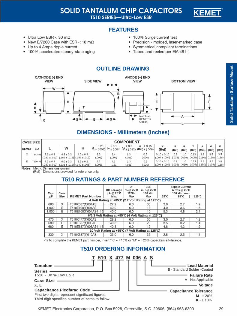
DF ESR Ripple CurrentDC Leakage % @ 25C m @ 25C A rms @ 25C
Cap. Case A @ 25C 120Hz 100 kHz 100 kHz, maxF Size KEMET Part Number Max Max Max 25°C 85°C 125°C
4 Volt Rating at +85C (2.7 Volt Rating at 125C)680 X T510X687(1)004AS 27.2 6.0 30 3.0 2.7 1.2
1,000 E T510E108(1)004AS 40.0 6.0 18 4.0 3.6 1.61,000 E T510E108(1)004AS4115 40.0 6.0 10 5.3 4.8 2.1
6/6.3 Volt Rating at +85C (4 Volt Rating at 125C)470 X T510X477(1)006AS 28.2 6.0 30 3.0 2.7 1.2680 E T510E687(1)006AS 40.8 6.0 23 3.5 3.2 1.4680 E T510E687(1)006AS4115 40.8 6.0 12 4.8 4.3 1.9
10 Volt Rating at +85C (7 Volt Rating at 125C)330 X T510X337(1)010AS 33.0 6.0 35 2.8 2.5 1.1
SOLID TANTALUM CHIP CAPACITORST510 SERIES—Ultra-Low ESR
KEMET Electronics Corporation, P.O. Box 5928, Greenville, S.C. 29606, (864) 963-6300 29
So
lid T
anta
lum
Su
rfac
e M
ou
nt
KEMET®
• Ultra Low ESR < 30 mΩ• New E/7260 Case with ESR < 18 mΩ• Up to 4 Amps ripple current• 100% accelerated steady-state aging
• 100% Surge current test• Precision - molded, laser-marked case• Symmetrical compliant terminations• Taped and reeled per EIA 481-1
FEATURES
Notch atKEMET'sOption
CATHODE (-) ENDVIEW
W
K
X
ANODE (+) ENDVIEW
R
P
BOTTOM VIEW
A
L
FE
SIDE VIEW
SGS
T
H
B
B
OUTLINE DRAWING
DIMENSIONS - Millimeters (Inches)
T510 RATINGS & PART NUMBER REFERENCE
T510 ORDERING INFORMATION
Notes: Metric Dimensions govern (Ref) - Dimensions provided for reference only.
2.3(.091)
K± 0.20± (.008)
0.10 ± 0.10(.004 ± .004)
KEMET EIA L W H X(Ref)
P(Ref)
R(Ref)
T(Ref)
A(Min)
G(Ref)
E(Ref)
X 7343-43 7.3 ± 0.3(.287 ± .012)
4.3 ± 0.3(.169 ± .012)
4.0 ± 0.3(.157 ± .012)
2.4(.094)
1.3(.051)
0.5(.020)
0.9(.035)
1.0(.039)
0.13(.005)
3.8(.150)
3.5(.138)
3.5(.138)
CASE SIZE COMPONENT
S± 0.3± (.012)F
± 0.1± (.004)
B(Ref)
± 0.15± (.006)
E 7260-38 7.3 ± 0.3(.287 ± .012)
6.0 ± 0.3(.236 ± .012)
3.6 ± 0.2(.142 ± .008)
2.3(.091)
4.1(.161
1.3(.051)
0.5(.020)
0.10 ± 0.10(.004 ± .004)
0.9(.035)
1.0(.039)
0.13(.005)
3.8(.150)
3.5(.138)
3.5(.138)
M477510 A006T X S
TantalumSeriesT510 - Ultra-Low ESR
Case SizeX, ECapacitance Picofarad CodeFirst two digits represent significant figures.Third digit specifies number of zeros to follow.
Lead Material
Failure Rate
Voltage
Capacitance Tolerance
A - Not Applicable
M - ± 20%K - ± 10%
S - Standard Solder -Coated
(1) To complete the KEMET part number, insert “K” – 10% or “M” – 20% capacitance tolerance.

SOLID TANTALUM CHIP CAPACITORST510 Series - Ultra-Low ESR
KEMET Electronics Corporation, P.O. Box 5928, Greenville, S.C. 29606, (864) 963-630030
KEMET®
100Hz 1kHz 10kHz 100kHz 1MHz.01
ES
R (
)
Z
(
)
(Ω
)
.1
1
10
0
50
100
150
200
250
300
350
400
450
500
Cap
acita
nce
(µF
)
100Hz 1kHz 10kHz 100kHz 1MHz
TYPICAL ESR/Z FREQUENCY SCAN @25˚CT510X477M006AS
TYPICAL CAP FREQUENCY SCAN @25˚CT510X477M006AS
CAPACITOR MARKINGS
T510 SERIES CONSTRUCTION
4 7 76 K
1 1 4
M+Ultra-LowESR Device
PicofaradCode
KEMETI. D. Symbol
RatedVoltage
1st Digit=Year
2nd & 3rd Digits= Week
PolarityIndicator (+)(Solid Stripe)
“114” = The 14th weekof 2001.
MoldedCase
Silver AdhesiveWasher
PositiveTermination*
Weld
NegativeTermination*
MnO2 Coat(First Layer)
Silver Paint(Third Layer)
TantalumWire
Carbon(Second Layer)
Tantalum(Ta2O5)
PolarityStripe (+)
PolarityBevel (+)
*Termination Solder Coating90Sn/10Pb

KEMET Electronics Corporation, P.O. Box 5928, Greenville, S.C. 29606, (864) 963-6300 31
So
lid T
anta
lum
Su
rfac
e M
ou
nt
SOLID TANTALUM CHIP CAPACITORST510 Series - Ultra-Low ESR
KEMET®
CAPACITOR MARKINGS
1 0 84 K
1 3 5
M+Ultra-LowESR Device
PicofaradCode
KEMETI. D. Symbol
RatedVoltage
1st Digit=Year
2nd & 3rd Digits= Week
PolarityIndicator (+)(Solid Stripe)
TYPICAL CAP FREQUENCY SCAN @ 25°CT510E108M004AS
TYPICAL ESR/Z FREQUENCY SCAN @ 25°CT510E108M004AS
Cap
acita
nce
(µF
)
100Hz 1kHz 10kHz 100kHz 1MHz500
600
700
800
900
1000
1100
1200
1300
1400
1500
100Hz 1kHz 10kHz 100kHz 1MHz.01
ES
R (
)
Z
(
)
(Ω
)
.1
1
10
T510E SERIES CONSTRUCTION
“135” = The 35th weekof 2001.

KEMET Electronics Corporation, P.O. Box 5928, Greenville, S.C. 29606, (864) 963-630032
KEMET®
IntroductionKEMET has developed a new type of tantalum capacitorthat replaces the solid manganese dioxide electrode witha solid conductive polymer. This product is named theKO-CAP for KEMET Organic Capacitor. The basic familyis the T520 series. A separate detail of performance char-acteristics is presented here as there are some differ-ences between the polymer tantalums and the standardMnO2 types. Like all KEMET tantalum chips, the T520series is 100% screened for all electrical parameters:Capacitance @ 120 Hz, Dissipation Factor (DF) @ 120 Hz,ESR @ 100 kHZ and DC Leakage. It is also 100% surgecurrent tested at full rated voltage through a low imped-ance circuit. The advantages of the polymer include verylow ESR and elimination of the potentially catastrophicfailure mode that may occur with standard tantalumcapacitors in a high surge current application. Althoughthe natural T520 series failure mechanism is a short cir-cuit, it does not exhibit an explosive failure mode.
ELECTRICAL1. Operating Temperature Range
• -55ºC to +105ºCAbove 85ºC, the voltage rating is reduced linearlyfrom 1.0 x rated voltage to 0.8 x rated voltage at105ºC.
2. Non-Operating Temperature Range• -55ºC to +105ºC
3. Capacitance and Tolerance• 68µF to 470µF• ±20% ToleranceCapacitance is measured at 120 Hz, up to 1.0 volt rmsmaximum and up to 2.5V DC maximum. DC bias caus-es only a small reduction in capacitance, up to about2% when full rated voltage is applied. DC bias is notcommonly used for room temperature measurementsbut is more commonly used when measuring at tem-perature extremes.Capacitance does decrease with increasing frequency,but not nearly as much or as quickly as standard tanta-lums. Figure 1 compares the frequency induced cap roll-off between the KO-CAP and traditional MnO2 types.Capacitance also increases with increasing tempera-ture. See section 12 for temperature coefficients.
4. Voltage Ratings• 4V-10V DC Rated VoltageThis is the maximum peak DC operating voltagefrom -55ºC to +85ºC for continuous duty. Above85ºC, this voltage is derated linearly to 0.8 timesthe rated voltage for operation at 105ºC.
• Surge Voltage RatingsSurge voltage is the maximum voltage to which thepart can be subjected under transient conditionsincluding the sum of peak AC ripple, DC bias andany transients. Surge voltage capability is demon-strated by application of 1000 cycles of the relevantvoltage, at 25ºC, 85ºC or 105ºC. The parts arecharged through a 33 ohm resistor for 30 secondsand then discharged through a 33 ohm resistor for30 seconds for each cycle.
• Voltage Ratings • Table 1Rated Surge Derated Derated
Voltage Voltage Voltage SurgeVoltage
-55ºC to +85ºC +105ºC4V 5.2V 3.3V 4.3V
6.3V 8V 5V 6.5V10V 13V 8V 10.4V
5. Reverse Voltage Rating & PolarityPolymer tantalum capacitors are polar devices andmay be permanently damaged or destroyed if con-nected in the wrong polarity. The positive terminalis identified by a laser-marked stripe and may alsoinclude a beveled edge. These capacitors will with-stand a small degree of transient voltage reversalfor short periods as shown in the following table.Please note that these parts may not be operatedcontinuously in reverse, even within these limits.
Table 2Temperature Permissible Transient Reverse Voltage
25ºC 15% of Rated Voltage55ºC 10% of Rated Voltage85ºC 5% of Rated Voltage105ºC 3% of Rated Voltage
6. DC Leakage CurrentBecause of the high conductivity of the polymer,the KO-CAP family has higher leakage currentsthan traditional MnO2 type Tantalum caps. The DCLeakage limits at 25ºC are calculated as 0.1 x C xV, where C is cap in µF and V is rated voltage inVolts. Limits for all part numbers are listed in theratings tables.
DC Leakage current is the current that flowsthrough the capacitor dielectric after a five minutecharging period at rated voltage. Leakage is mea-sured at 25ºC with full rated voltage applied to thecapacitor through a 1000 ohm resistor in serieswith the capacitor.
COMPONENT PERFORMANCE CHARACTERISTICS
10
100
1,000
10,000
100,000
1,000,000
10,000,000
100,000,000
Frequency (Hz)
0
50
100
150
Capacitance (uF)
PolymerMnO2
FIGURE 1
POLYMER TANTALUM CHIP CAPACITORS

KEMET Electronics Corporation, P.O. Box 5928, Greenville, S.C. 29606, (864) 963-6300 33
KEMET®
Poly
mer
Tan
talu
m S
urfa
ce M
ount
COMPONENT PERFORMANCE CHARACTERISTICSDC Leakage current does increase with tempera-ture. The limits for 85ºC @ Rated Voltage and105ºC @ 0.8 x Rated Voltage are both 10 timesthe 25ºC limit.
7. Surge Current CapabilityCertain applications may induce heavy surge cur-rents when circuit impedance is very low (<0.1ohm per volt). Driving inductance may also causevoltage ringing. Surge currents may appear astransients during turn-on of equipment.
The KO-CAP has a very high tolerance for surgecurrent. And although the failure mechanism is ashort circuit, they do not explode as may occurwith standard tantalums in such applications.
The T520 series receives 100% screening forsurge current in our production process.Capacitors are surged 4 times at full rated voltageapplied through a total circuit resistance of <0.5ohms. Failures are removed during subsequentelectrical testing.
8. Dissipation Factor (DF)Refer to part number tables for maximum DF limits.
Dissipation factor is measured at 120 Hz, up to 1.0volt rms maximum, and up to 2.5 volts DC maxi-mum at +25ºC. The application of DC bias causesa small reduction in DF, about 0.2% when fullrated voltage is applied. DF increases withincreasing frequency.
Dissipation factor is the ratio of the equivalentseries resistance (ESR) to the capacitive reac-tance, (XC) and is usually expressed as a percent-age. It is directly proportional to both capacitanceand frequency. Dissipation factor loses its impor-tance at higher frequencies, (above about 1 kHz),where impedance (Z) and equivalent series resis-tance (ESR) are the normal parameters of concern.DF = R = 2 f CR DF= Dissipation Factor
XC R= Equivalent SeriesResistance (Ohms)
XC= Capacitive Reactance(Ohms)
f= Frequency (Hertz)C= Series Capacitance
(Farads)
DF is also referred to as tan or “loss tangent.”The “Quality Factor,” “Q,” is the reciprocal of DF.
9. Equivalent Series Resistance (ESR) and Impedance (Z)The Equivalent Series Resistance (ESR) of the KO-CAP is much lower than standard Tantalum capsbecause the polymer cathode has much higherconductivity. ESR is not a pure resistance, and itdecreases with increasing frequency.
Total impedance of the capacitor is the vectorsum of capacitive reactance (XC) and ESR, belowresonance; above resonance total impedance isthe vector sum of inductive reactance (XL) andESR.
XC = 1 ohm2fC
where:f = frequency, HertzC = capacitance, Farad
FIGURE 2a Total Impedance of the Capacitor Below Resonance
XL = 2fL
where:f = frequency, HertzL = inductance, Henries
FIGURE 2b Total Impedance of the Capacitor AboveResonance
To understand the many elements of a capaci-tor, see Figure 3.
POLYMER TANTALUM CHIP CAPACITORS

KEMET Electronics Corporation, P.O. Box 5928, Greenville, S.C. 29606, (864) 963-630034
KEMET®
p.39. Maximum limits for 100 kHz ESR are listedin the part number tables for each series.
10. AC Power DissipationPower dissipation is a function of capacitor sizeand materials. Maximum power ratings have beenestablished for all case sizes to prevent overheat-ing. In actual use, the capacitor’s ability to dissi-pate the heat generated at any given power levelmay be affected by a variety of circuit factors.These include board density, pad size, heat sinksand air circulation.
Table 3Tantalum Chip Power Dissipation RatingsCase Code Maximum Power Dissipation
KEMET EIA Watts @ +25ºCV 7343-20 0.125D 7343-31 0.150X 7343-43 0.165
11. AC OperationPermissible AC ripple voltage and current arerelated to equivalent series resistance (ESR) andpower dissipation capability.
Permissible AC ripple voltage which may beapplied is limited by three criteria:
a. The positive peak AC voltage plus the DC biasvoltage, if any, must not exceed the DC voltagerating of the capacitor.
b. The negative peak AC voltage, in combinationwith bias voltage, if any, must not exceed thepermissible reverse voltage ratings presentedin Section 5.
c. The power dissipated in the ESR of the capaci-tor must not exceed the appropriate valuespecified in Section 10.
COMPONENT PERFORMANCE CHARACTERISTICS
A capacitor is a complex impedance consistingof many series and parallel elements, eachadding to the complexity of the measurementsystem.
L — Represents lead wire and constructioninductance. In most instances (especially insolid tantalum and monolithic ceramic capaci-tors) it is insignificant at the basic measurementfrequencies of 120 and 1000 Hz.
RS — Represents the actual ohmic series resis-tance in series with the capacitance. Lead wiresand capacitor electrodes are contributingsources.
RL — Capacitor Leakage Resistance. Typically itcan reach 50,000 megohms in a tantalumcapacitor. It can exceed 1012 ohms in monolithicceramics and in film capacitors.
Rd — The dielectric loss contributed by dielectricabsorption and molecular polarization. Itbecomes very significant in high frequency mea-surements and applications. Its value varies withfrequency.
Cd — The inherent dielectric absorption of thesolid tantalum capacitor which typically equatesto 1-2% of the applied voltage.
As frequency increases, XC continues todecrease according to its equation above. Thereis unavoidable inductance as well as resistancein all capacitors, and at some point in frequency,the reactance ceases to be capacitive andbecomes inductive. This frequency is called theself-resonant point. In solid tantalum capacitors,the resonance is damped by the ESR, and asmooth, rather than abrupt, transition fromcapacitive to inductive reactance follows.
Figure 4 compares the frequency response of aKO-CAP to a standard Tantalum chip. See alsofrequency curves shown in the T520 section,
L RS C
RL
Cd Rd
FIGURE 3 The Real Capacitor
T495D 150 uF (MnO2) vs. T520D 150 uF (Polymer)
100 1,000 10,000 100,000 1,000,000 10,000,000
Frequency (Hz)
0.01
0.1
1
10
100
Impedance & ESR (Ohms)
Polymer
MnO2
ESR and Impedance
FIGURE 4
POLYMER TANTALUM CHIP CAPACITORS

KEMET Electronics Corporation, P.O. Box 5928, Greenville, S.C. 29606, (864) 963-6300 35
KEMET®
Poly
mer
Tan
talu
m S
urfa
ce M
ount
14. High Temperature Life Test• 105ºC, 0.8 x Rated Voltage, 2000 hoursPost Test Performance:
a. Capacitance: within ±10% of initial valueb. DF: within initial limitc. DC Leakage: within 1.25 x initial limitd. ESR: within 2 x initial limit
15. Storage Life Test• 105ºC, 0VDC, 2000 HoursPost Test Perfomance:
a. Capacitance: within ±10% of initial valueb. DF: within initial limitc. DC Leakage: within 1.25 x initial limitd. ESR: within 2 x initial limit
16. Thermal Shock• Mil-Std-202, Method 107, Condition BMinimum temperature is -55ºCMaximum temperature is +105ºC500 CyclesPost Test Performance:
a. Capacitance: within ±10% of initial valueb. DF: within initial limitc. DC Leakage: within initial limitd. ESR: within 2 x initial limit
17. Moisture Resistance• Mil-Std-202, Method 106Steps 7a and 7b excluded, 0V, 21 cyclesPost Test Performance:
a. Capacitance: within ±20% of initial valueb. DF: within initial limitc. DC Leakage: within initial limitd. ESR: within 2 x initial limit
18. Load Humidity• 85ºC, 85% RH, Rated Voltage, 500 HoursPost Test Performance:
a. Capacitance: within ±20% of initial valueb. DF: within initial limitc. DC Leakage: within 5 x initial limitd. ESR: within 2 x initial limit
19. ESD• Polymer tantalum capacitors are not sensitiveto Electro-Static Discharge (ESD).
20. Failure Mechanism and ReliabilityThe normal failure mechanism is dielectric break-down. Dielectric failure can result in high DCLeakage current and may proceed to the level of ashort circuit. With sufficient time to charge, heal-ing may occur by one of two potential mecha-nisms. The polymer adjacent to the dielectric faultsite may overheat and vaporize, disconnecting thefault site from the circuit. The polymer may also
Actual power dissipated may be calculated fromthe following:P =I2RSubstituting I = E, P = E2R
Z Z2
where:I = rms ripple current (amperes)E = rms ripple voltage (volts)P = power (watts)Z = impedance at specified frequency (ohms)R = equivalent series resistance at specified
frequency (ohms)Using P max from Table 3, maximum allowablerms ripple current or voltage may be determined asfollows:I(max) = P max/R E(max) = Z P max/RThese values should be derated at elevated tem-peratures as follows:
Temperature Derating Factor85ºC .9
105ºC .4
ENVIRONMENTAL
12. Temperature StabilityMounted capacitors withstand extreme tempera-ture testing at a succession of continuous stepsat +25ºC, -55ºC, +25ºC, +85ºC, +105ºC, +25ºC inthat order. Capacitors are allowed to stabilize ateach temperature before measurement. Cap, DF,and DCL are measured at each temperatureexcept DC Leakage is not measured at -55ºC.
Table 4Acceptable limits are as follows:
Step Temp. ∆Cap DCL DF1 +25ºC Specified Catalog Catalog
Tolerance Limit Limit2 -55ºC ±20% of N/A Catalog
initial value Limit3 +25ºC ±10% of Catalog Catalog
initial value Limit Limit4 +85ºC ±20% of 10x Catalog 1.2x Catalog
initial value Limit Limit5 +105ºC ±30% of 10x Catalog 1.5x Catalog
initial value Limit Limit6 +25ºC ±10% of Catalog Catalog
initial value Limit Limit
13. Standard Life Test• 85ºC, Rated Voltage, 2000 HoursPost Test Performance:
a. Capacitance: within ±10% of initial valueb. DF: within initial limitc. DC Leakage: within initial limitd. ESR: within initial limit
COMPONENT PERFORMANCE CHARACTERISTICS
POLYMER TANTALUM CHIP CAPACITORS

KEMET Electronics Corporation, P.O. Box 5928, Greenville, S.C. 29606, (864) 963-630036
KEMET®
26. Vibration• Mil-Std-202, Method 204, Condition D, 10 Hzto 2,000 Hz, 20G PeakPost Test Performance:a. Capacitance — within ±10% of initial valueb. DC Leakage — within initial limitc. Dissipation Factor — within initial limitd. ESR — within initial limit
27. Shock• Mil-Std-202, Method 213, Condition I,100 G PeakPost Test Performance:a. Capacitance — within ±10% of initial valueb. DC Leakage — within initial limitc. Dissipation Factor — within initial limitd. ESR - within initial limit
28. Terminal Strength• Pull Force
• One Pound (454 grams), 30 Seconds
• Tensile Force• Four Pounds (1.8 kilograms), 60 Seconds
• Shear ForceTable 5 Maximum Shear Loads
Case Code Maximum Shear LoadsKEMET EIA Kilograms Pounds
V 7343-20 5.0 11.0D 7343-31 5.0 11.0X 7343-43 5.0 11.0
Post Test Performance:a. Capacitance — within ±5% of initial valueb. DC Leakage — within initial limitc. Dissipation Factor — within initial limitd. ESR - within initial limit
Failure rates may be improved in application byderating the voltage applied to the capacitor.KEMET recommends that KO-CAPs be deratedto 80% or less of the rated voltage in application.
KO-CAPs exhibit a benign failure mode in thatthey do not fail catastophically even under typicalfault conditions. If a shorted capacitor is allowedto pass unlimited current, it may overheat and thecase may discolor. But this is distinctly differentfrom the explosive “ignition” that may occur withstandard MnO2 cathode tantalums. Replacementof the MnO2 by the polymer removes the oxygenthat fuels ignition during a failure event.
MECHANICAL
21. Resistance to Solvents• Mil-Std-202, Method 215Post Test Performance:
a. Capacitance — within ±10% of initial valueb. DC Leakage — within initial limitc. Dissipation Factor — within initial limitd. ESR — within initial limite. Physical — no degradation of case, terminalsor marking
22. Fungus• Mil-Std-810, Method 508
23. Flammability• UL94 VO ClassificationEncapsulant materials meet this classifaction
24. Resistance to Soldering Heat• Maximum Reflow
+240 ±5ºC, 10 seconds• Typical Reflow
+230 ±5ºC, 30 secondsPost Test Performance:a. Capacitance — within ±10% of initial valueb. DC Leakage — within initial limitc. Dissipation Factor — within initial limitd. ESR — within initial limit
25. Solderability• Mil-Std-202, Method 208• ANSI/J-STD-002, Test BApplies to Solder Coated terminations only.
COMPONENT PERFORMANCE CHARACTERISTICS
4 lb. (1.8 Kg)
oxidize into a more resistive material that plugsthe defect site in the dielectric and reduces theflow of current.
Capacitor failure may be induced by exceedingthe rated conditions of forward DC voltage,reverse DC voltage, surge current, power dissipa-tion or temperature. Excessive environmentalstress, such as prolonged or high temperaturereflow processes may also trigger dielectric failure.
POLYMER TANTALUM CHIP CAPACITORS

KEMET Electronics Corporation, P.O. Box 5928, Greenville, S.C. 29606, (864) 963-6300 37
KEMET®
Poly
mer
Tan
talu
m S
urfa
ce M
ount
thermal stress. The maximum recommended preheat rate is 2ºC per second.
Hand-soldering should be avoided. If necessary,it should be performed with care due to the diffi-culty in process control. Care should be taken toavoid contact of the soldering iron to the moldedcase. The iron should be used to heat the solderpad, applying solder between the pad and thetermination, until reflow occurs. The iron shouldbe removed. “Wiping” the edges of a chip andheating the top surface is not recommended.
During typical reflow operations a slight darken-ing of the gold-colored epoxy may be observed.This slight darkening is normal and is not harmfulto the product. Marking permanency is not affect-ed by this change.
33. WashingStandard washing techniques and solvents arecompatible with all KEMET surface mount tanta-lum capacitors. Solvents such as Freon TMC andTMS, Trichlorethane, methylene chloride, prelete,and isopropyl alcohol are not harmful to thesecomponents. Please note that we are not endors-ing the use of banned or restricted solvents. Weare simply stating that they would not be harmfulto the components.
If ultrasonic agitation is utilized in the cleaningprocess, care should be taken to minimize energylevels and exposure times to avoid damage to theterminations.
KEMET tantalum chips are also compatible withnewer aqueous and semi-aqueous processes.Contact KEMET for Engineering Bulletin F-2109entitled “Alternative Surface Mount CleaningProcesses” for further details on this subject.
34. EncapsulationsUnder normal circumstances, potting or encapsu-lation of KEMET tantalum chips is not required.
35. Storage EnvironmentTantalum chip capacitors should be stored in nor-mal working environments. While the chips them-selves are quite robust in other environments,solderability will be degraded by exposure to hightemperatures, high humidity, corrosive atmos-pheres, and long term storage. In addition, pack-aging materials will be degraded by high temper-ature - reels may soften or warp, and tape peelforce may increase. KEMET recommends thatmaximum storage temperature not exceed 40degrees C, and the maximum storage humiditynot exceed 60% relative humidity. In addition,temperature fluctuations should be minimized toavoid condensation on the parts, and atmos-pheres should be free of chlorine and sulfur bear-ing compounds. For optimized solderability, chipstock should be used promptly, preferably within1.5 years of receipt.
30. Termination CoatingThe standard finish coating is 90/10 Sn/Pb solder(Tin/Lead-solder coated).
31. Recommended Mounting Pad GeometriesProper mounting pad geometries are essential forsuccessful solder connections. These dimensionsare highly process sensitive and should bedesigned to maximize the intergrity of the solderjoint, and to minimize component rework due tounacceptable solder joints.
Figure 5 illustrates pad geometry. The table pro-vides recommended pad dimensions for reflowsoldering techniques. These dimensions areintended to be a starting point for circuit boarddesigners, to be fine tuned, if necessary, basedupon the peculiarities of the soldering processand/or circuit board design.
Contact KEMET for Engineering Bulletin Number F-2100 entitled “Surface Mount Mounting PadDimensions and Considerations” for furtherdetails on this subject.
Table 6 - Land Pattern Dimensions for Reflow SolderPad Dimensions
Y CZ G X (ref) (ref)
D/7343-31, V/7343-20, X/7343-43 8.90 3.80 2.70 2.55 6.35
32. SolderingThe T520 KO-CAP family has been designed forreflow solder processes. They are not recom-mended for wave solder. Solder-coated termina-tions have excellent wetting characteristics forhigh integrity solder fillets. Preheating of thesecomponents is recommended to avoid extreme
COMPONENT PERFORMANCE CHARACTERISTICS
Figure 5
KEMET/EIA Size Code
POLYMER TANTALUM CHIP CAPACITORS
APPLICATIONS
29. HandlingAutomatic handling of encapsulated componentsis enhanced by the molded case which providescompatibility with all types of high speed pick andplace equipment. Manual handling of thesedevices presents no unique problems. Careshould be taken with your fingers, however, toavoid touching the solder-coated terminations asbody oils, acids and salts will degrade the sol-derability of these terminations. Finger cotsshould be used whenever manually handling allsolderable surfaces.

KEMET Electronics Corporation, P.O. Box 5928, Greenville, S.C. 29606, (864) 963-630038
KEMET®
Case SizeKEMET EIA L W H K 0.20 F 0.1 S 0.3 X(Ref) T(Ref) A(Min) G(ref) E(ref)
Outline Drawing
Features• Polymer Cathode Technology • Capacitance 68 to 470µF (±20%)• Low ESR • Voltage 4V to 10V• High Frequency Cap Retention • EIA Standard Case Sizes• No-Ignition Failure Mode • 100% Surge Current Tested
POLYMER TANTALUM CHIP CAPACITORST520 SERIES

KEMET Electronics Corporation, P.O. Box 5928, Greenville, S.C. 29606, (864) 963-6300 39
KEMET®
Poly
mer
Tan
talu
m S
urfa
ce M
ount
Measured Capacitance (F)T520V157M006AS @ +25ºC with 3VDC Bias
Measured Inductance (H)
T520V157M006AS @ +25ºC with 3VDC Bias
Z
ESR
100kHz30.5mOhm28.6 mOhm2.4 nH
FreqZRL
Measured Capacitance (F)T520D337M006AS @ +25ºC with 3VDC Bias
100 kHz189.2 uF160.4 uF
FreqMeasured Cap
Actual Cap
Measured Inductance (H)
T520D337M006AS @ +25ºC with 3VDC Bias
Z
ESR
100 kHz29.1 mOhm27.9 mOhm2.4 nH
FreqZRL
100m
Impedance and ESR (Ohms)
Frequency (Hz)
10
1
10m
1k 10k 100k 1M 10M100
Impedance and ESR (Ohms)
Frequency (Hz)
10
1
10m
1k 10k 100k 1M 10M100
100m
100 kHz150.3 uF131.6 uF
FreqMeasured Cap
Actual Cap
1m
100u
100 1k 10k 100k 1M 10M
Frequency (Hz)
CAP
L
C
10u 100p
1n
10n1m
100u
100 1k 10k 100k 1M 10M
Frequency (Hz)
CAP L
C
10u 100p
1n
10n
KEMETOrganic
157 6K112
KO
RatedVoltage
Polarity (+)Indicator
PicofaradCode
KEMET ID
PWC
112 = 12th week of 2001
T 520
Capacitance Picofarad CodeFirst two digits represent significant figures.Third digit specifies number of zeros to follow
Case SizeV, D, X
Tantalum
SeriesT520 - Low ESR Polymer
Capacitance ToleranceM - ± 20%
Lead MaterialS - Standard Solder Coated
Failure RateA - Not Applicable
Voltage
V 157 M 006 A S
Typical Frequency Response Curves
Component Marking
T520 Ordering Information
POLYMER TANTALUM CHIP CAPACITORST520 SERIES
T520 Series Construction

KEMET Electronics Corporation, P.O. Box 5928, Greenville, S.C. 29606, (864) 963-630058
KEMET®
Tape & Reel Packaging
KEMET’s Molded Tantalum Chip Capacitor families arepackaged in 8 mm and 12 mm plastic tape on 7" and 13"reels, in accordance with EIA Standard 481-1: Taping ofSurface Mount Components for Automatic Handling. Thispackaging system is compatible with all tape fed auto-matic pick and place systems.
Right HandOrientation
Only
(+) (–)
Embossed Carrier
Embossment
Top Tape Thickness.10mm (.004") Max Thickness
8mm ±.30(.315 ±.012")
or12mm ±.30
(.472 ±.012")178mm (7.00")
or330mm (13.00")
8mm (0.315")or
12mm (0.472") 180mm (7.0")or
330mm (13.0")
QUANTITIES PACKAGED PER REEL
Case Code TapeKEMET EIA Width-mm 7" Reel* 13" Reel*
R 2012-12 8 2,500 10,000S 3216-12 8 2,500 10,000T 3528-12 8 2,500 10,000U 6032-15 12 1,000 5,000V 7343-20 12 1,000 3,000A 3216-18 8 2,000 9,000B 3528-21 8 2,000 8,000C 6032-28 12 500 3,000D 7343-31 12 500 2,500X 7343-43 12 500 2,000E 7260-38 12 500 2,000
* No c-spec required for 7" reel packaging. C-7280 required for 13" reel packaging.
Labeling: Bar code labeling (standard or custom) shall be on the side of the reel opposite the sprocket holes.Refer to EIA-556.
TANTALUM CHIP CAPACITORSPackaging Information

KEMET Electronics Corporation, P.O. Box 5928, Greenville, S.C. 29606, (864) 963-630060
KEMET®
Performance Notes1. Cover Tape Break Force: 1.0 Kg Minimum.2. Cover Tape Peel Strength: The total peel strength of the cover tape from the carrier tape shall be:
Tape Width Peel Strength8 mm 0.1 Newton to 1.0 Newton (10g to 100g)
12 mm 0.1 Newton to 1.3 Newton (10g to 130g)The direction of the pull shall be opposite the direction of the carrier tape travel. The pull angle of the carriertape shall be 165 to 180 from the plane of the carrier tape. During peeling, the carrier and/or cover tapeshall be pulled at a velocity of 300 ±10 mm/minute.
3. Reel Sizes: Molded tantalum capacitors are available on either 180 mm (7") reels (standard) or 330 mm (13")reels (with C-7280). Note that 13” reels are preferred.
4. Labeling: Bar code labeling (standard or custom) shall be on the side of the reel opposite the sprocket holes.Refer to EIA-556.
Embossed Carrier Tape Configuration: Figure 1
NOTES1. B1 dimension is a reference dimension for tape feeder clearance only.2. The embossment hole location shall be measured from the sprocket hole controlling the location of the embossment. Dimensions of
embossment location and hole location shall be applied independent of each other.3. Tape with components shall pass around radius “R” without damage (see sketch A). The minimum trailer length (Fig. 2) may require
additional length to provide R min. for 12 mm embossed tape for reels with hub diameters approaching N min. (Table 2)4. The cavity defined by A0, B0, and K0 shall be configured to surround the part with sufficient clearance such that the chip does not pro-
trude beyond the sealing plane of the cover tape, the chip can be removed from the cavity in a vertical direction without mechanicalrestriction, rotation of the chip is limited to 20 degrees maximum in all 3 planes, and lateral movement of the chip is restricted to 0.5 mmmaximum in the pocket (not applicable to vertical clearance.)
Table 1 — EMBOSSED TAPE DIMENSIONS (Metric will govern)
Constant Dimensions — Millimeters (Inches)
Tape Size D0 E P0 P2 T Max T1 Max
8 mm 1.5 1.75 ±0.10 4.0 ±0.10 2.0 ±0.05 0.600 0.100and +0.10 -0.0
12 mm (0.059 (0.069 ±0.004) (0.157 ±0.004) (0.079 ±0.002) (0.024) (0.004)+0.004, -0.0)
Variable Dimensions — Millimeters (Inches)Tape Size Pitch B1 Max. D1 Min. F P1 R Min. T2 Max W A0B0K0
Note 1 Note 2 Note 3 Note 4
8 mm Single 4.4 1.0 3.5 ±0.05 4.0 ±0.10 25.0 2.5 8.0(4 mm) +0.3 -0.1
(0.173) (0.039) (0.138 ±0.002) (0.157 ±0.004) (0.984) (0.098) (0.315+0.012, -0.004)
12 mm Double 8.2 1.5 5.5 ±0.05 8.0 ±0.10 30.0 4.6 12.0 ±0.30(8 mm) (0.323) (0.059) (0.217 ±0.002) (0.315 ±0.004) (1.181) (0.181) (0.472 ±0.012)
TANTALUM & CERAMIC CHIP CAPACITORSPackaging Information

KEMET Electronics Corporation, P.O. Box 5928, Greenville, S.C. 29606, (864) 963-6300 61
KEMET®
Pac
kag
ing
Tantalum & Embossed Carrier Tape Configuration (cont.)
Sketch D: Tape Camber (Top View)
Allowable camber to be 1 mm/250 mm.250mm (9.843)
1mm (0.039) Max.
1mm (0.039) Max.
Table 2 – REEL DIMENSIONS (Metric will govern)
Figure 3: Reel Dimensions (Metric Dimensions will govern)
Tape Size A Max B* Min C D* Min N Min W1 W2 Max W3
8 mm 330.0 1.5 13.0 ± 0.20 20.2 50.0 8.4 14.4 7.9 Min(12.992) (0.059) (0.512 ± 0.008) (0.795) (1.969) +1.5, -0.0 (0.567) (0.311)
See (0.331 10.9 MaxNote 3 +0.059, -0.0) (0.429)
12 mm 330.0 1.5 13.0 ± 0.20 20.2 Table 1 12.4 18.4 11.9 Min(12.992) (0.059) (0.512 ± 0.008) (0.795) +2.0, -0.0 (0.724) (0.469)
(0.488 15.4 Max+0.078, -0.0) (0.606)
TANTALUM & CERAMIC CHIP CAPACITORSPackaging Information
*Ceramic trailer – 80mm (3.15) *Ceramic Leader – 320mm (12.60)
Figure 2:Tape Leader& TrailerDimensions(MetricDimensionsWill Govern)