incus ultrasonic gas leak detector - · pdf fileincus ultrasonic gas leak detector march 2017...
TRANSCRIPT

Incus Ultrasonic Gas Leak DetectorFGD-PDS-Incus-Ultrasonic-Gas-Leak-Detector
Product Data SheetMarch 2017
Incus Ultrasonic Gas Leak DetectorWide Area Coverage for Pressurized Gas Leaks
Incus Ultrasonic Gas Leak Detector
The Incus is an advanced gas leak detector that uses four sensitive acoustic sensors to monitor wide areas for the ultrasound generated from pressurized gas releases.
Ideally suited for monitoring ventilated outdoor applications, the Incus has been engineered to withstand extreme conditions. Detection is unaffected by inclement weather, wind, leak direction, or gas dilution, with fast speed of response.
� Instantaneous response to all gas leaks (toxic, combustible, or inert)
� Operates in extreme temperatures � Automated electronic self-test offers failsafe operation � Widest area of coverage through four independent sensors � 4–20 mA analog or stepped, “multi-drop” RS-485 digital
interface, and HART® communication protocol � Certified worldwide for hazardous locations � Innovative mapping tool helps optimize coverage for a
target risk � Programmable time delays screen intermittent unwanted
alarm sources
Four Multi-Directional Sensor HeadsQuad sensing heads provide the widest overall detection range available on the market. The sensing heads are independent with the detector output being based on the highest ultrasound measured by any one head. If one or more sensing heads fails complete coverage is not lost.
Field-proven Ultrasonic Sensor PrincipleIncus responds to the ultrasound produced by pressurized gas releases, a technology proven with hundreds of detectors installed worldwide.
Sensor Design - They Just Keep WorkingEach sensor is completely free of moving parts and will not age, drift, and never need replacing under normal operating conditions. Maintenance free protection with proven reliability.
Continuous Self-test Ensures Instrument HealthElectronic self-test checks the detector every 320 ms bysending an amplitude signal through the sensing circuitry.The sensor suffers no loss of detection while in test mode in contrast to those based on diaphragm microphones.
Built for Extreme ConditionsThe Incus is designed to operate at -40 °C to +85 °C and may be supplied for monitoring areas of regard at -55 °C. Corrosion resistant stainless steel housing is standard, units are ingress rated to IP66/67 or NEMA Type 4X.
Sealed Sensor HousingPiezoceramic sensor heads have no moving parts and can therefore be completely sealed against moisture, corrosive atmospheres, and industrial contaminants.
Incus Ultrasonic Gas Leak Detector March 2017
Figure 3
Figure 1
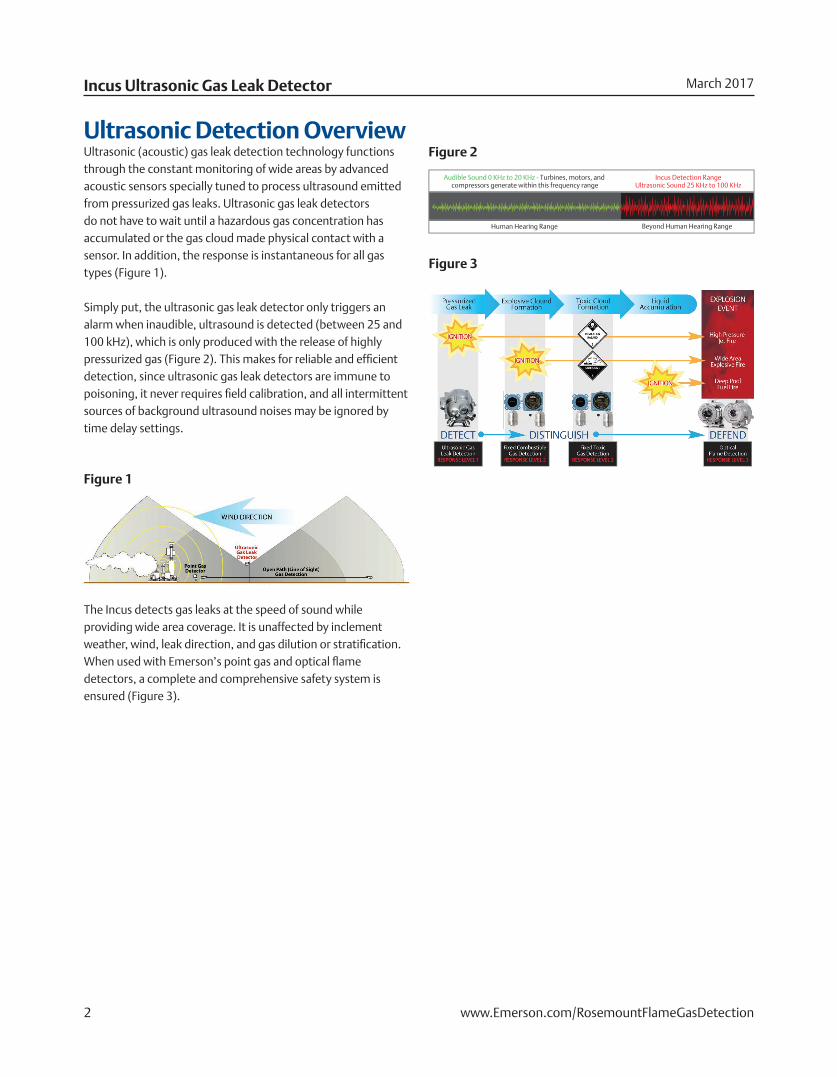
Figure 2Ultrasonic Detection OverviewUltrasonic (acoustic) gas leak detection technology functions through the constant monitoring of wide areas by advanced acoustic sensors specially tuned to process ultrasound emitted from pressurized gas leaks. Ultrasonic gas leak detectors do not have to wait until a hazardous gas concentration has accumulated or the gas cloud made physical contact with a sensor. In addition, the response is instantaneous for all gas types (Figure 1).
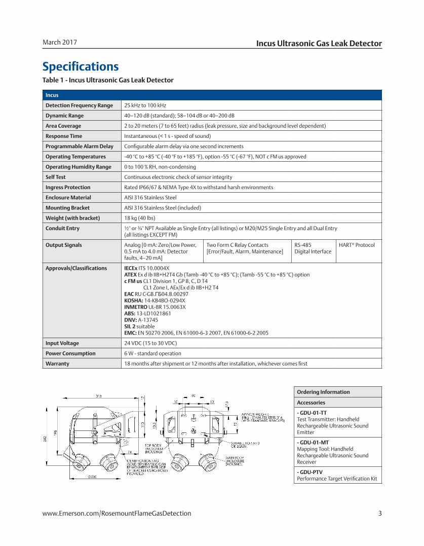
Simply put, the ultrasonic gas leak detector only triggers an alarm when inaudible, ultrasound is detected (between 25 and 100 kHz), which is only produced with the release of highly pressurized gas (Figure 2). This makes for reliable and efficient detection, since ultrasonic gas leak detectors are immune to poisoning, it never requires field calibration, and all intermittent sources of background ultrasound noises may be ignored by time delay settings.
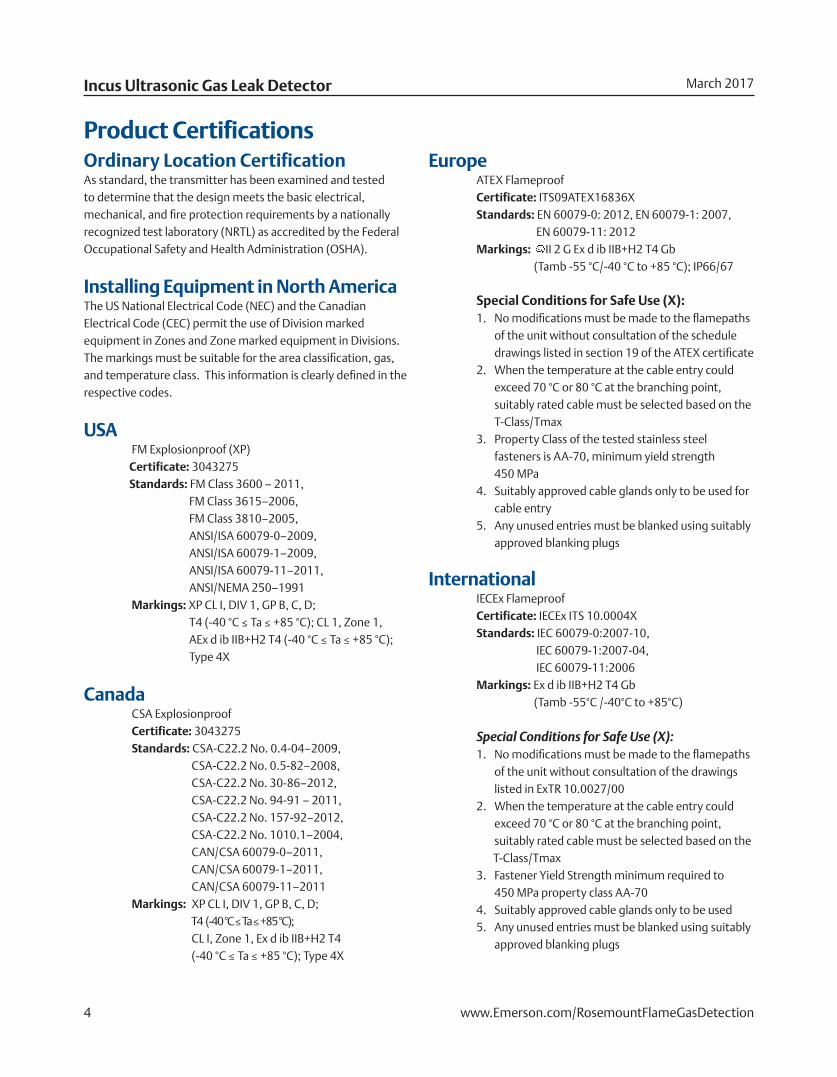
Fixed ToxicGas Detection
RESPONSE LEVEL 2
Pressurized Gas Release Response Levels — Detect • Distinguish • Defend
Toxic CloudFormation
LiquidAccumulation
High PressureJet Fire
Wide AreaExplosive Fire
Deep PoolFuel Fire
PressurizedGas Leak
EXPLOSIONEVENT
IGNITIONIGNITION
IGNITIONIGNITION
IGNITIONIGNITION
Ultrasonic GasLeak Detection
RESPONSE LEVEL 1
DETECT DEFENDDISTINGUISH
Human Hearing Range
Audible Sound 0 KHz to 20 KHz - Turbines, motors, and compressors generate within this frequency range
Beyond Human Hearing Range
Incus Detection RangeUltrasonic Sound 25 KHz to 100 KHz
Fixed CombustibleGas Detection
RESPONSE LEVEL 2
OpticalFlame Detection
RESPONSE LEVEL 3
Explosive CloudFormation
The Incus detects gas leaks at the speed of sound while providing wide area coverage. It is unaffected by inclement weather, wind, leak direction, and gas dilution or stratification. When used with Emerson’s point gas and optical flame detectors, a complete and comprehensive safety system is ensured (Figure 3).
2 www.Emerson.com/RosemountFlameGasDetection
Incus Ultrasonic Gas Leak DetectorMarch 2017
Incus
Detection Frequency Range 25 kHz to 100 kHz
Dynamic Range 40–120 dB (standard); 58–104 dB or 40–200 dB
Area Coverage 2 to 20 meters (7 to 65 feet) radius (leak pressure, size and background level dependent)
Response Time Instantaneous (< 1 s - speed of sound)
Programmable Alarm Delay Configurable alarm delay via one second increments
Operating Temperatures -40 °C to +85 °C (-40 °F to +185 °F), option -55 °C (-67 °F), NOT c FM us approved
Operating Humidity Range 0 to 100 % RH, non-condensing
Self Test Continuous electronic check of sensor integrity
Ingress Protection Rated IP66/67 & NEMA Type 4X to withstand harsh environments
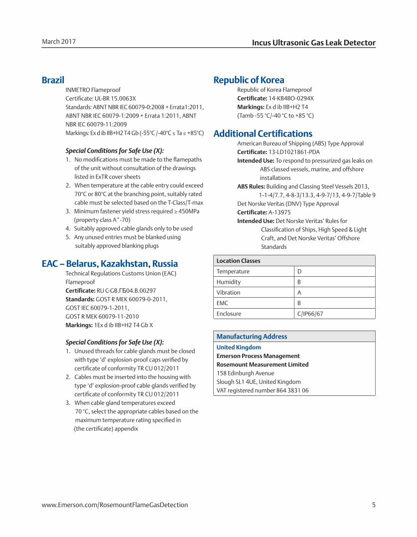
Enclosure Material AISI 316 Stainless Steel
Mounting Bracket AISI 316 Stainless Steel (included)
Weight (with bracket) 18 kg (40 lbs)
Conduit Entry ½'' or ¾'' NPT Available as Single Entry (all listings) or M20/M25 Single Entry and all Dual Entry (all listings EXCEPT FM)
Output Signals Analog [0 mA: Zero/Low Power, 0.5 mA to 4.0 mA: Detector faults, 4–20 mA]
Two Form C Relay Contacts[Error/Fault, Alarm, Maintenance]
RS-485 Digital Interface
HART® Protocol
Approvals/Classifications IECEx ITS 10.0004XATEX Ex d ib IIB+H2T4 Gb (Tamb -40 °C to +85 °C); (Tamb -55 °C to +85 °C) optionc FM us CL1 Division 1, GP B, C, D T4 CL1 Zone I, AEx/Ex d ib IIB+H2 T4 EAC RU C-GB.ГБ04.B.00297KOSHA: 14-KB4BO-0294XINMETRO UL-BR 15.0063XABS: 13-LD1021861DNV: A-13745SIL 2 suitableEMC: EN 50270 2006, EN 61000-6-3 2007, EN 61000-6-2 2005
Input Voltage 24 VDC (15 to 30 VDC)
Power Consumption 6 W - standard operation
Warranty 18 months after shipment or 12 months after installation, whichever comes first
SpecificationsTable 1 - Incus Ultrasonic Gas Leak Detector
Ordering Information
Accessories
- GDU-01-TTTest Transmitter: HandheldRechargeable Ultrasonic Sound Emitter
- GDU-01-MTMapping Tool: Handheld Rechargeable Ultrasonic Sound Receiver
- GDU-PTVPerformance Target Verification Kit
3www.Emerson.com/RosemountFlameGasDetection
Product Certifications Ordinary Location CertificationAs standard, the transmitter has been examined and tested to determine that the design meets the basic electrical, mechanical, and fire protection requirements by a nationally recognized test laboratory (NRTL) as accredited by the Federal Occupational Safety and Health Administration (OSHA).
Installing Equipment in North AmericaThe US National Electrical Code (NEC) and the Canadian Electrical Code (CEC) permit the use of Division marked equipment in Zones and Zone marked equipment in Divisions. The markings must be suitable for the area classification, gas, and temperature class. This information is clearly defined in the respective codes.
USA FM Explosionproof (XP) Certificate: 3043275 Standards: FM Class 3600 – 2011, FM Class 3615–2006, FM Class 3810–2005, ANSI/ISA 60079-0–2009, ANSI/ISA 60079-1–2009, ANSI/ISA 60079-11–2011, ANSI/NEMA 250–1991 Markings: XP CL I, DIV 1, GP B, C, D; T4 (-40 °C ≤ Ta ≤ +85 °C); CL 1, Zone 1, AEx d ib IIB+H2 T4 (-40 °C ≤ Ta ≤ +85 °C); Type 4X
Canada CSA Explosionproof Certificate: 3043275 Standards: CSA-C22.2 No. 0.4-04–2009, CSA-C22.2 No. 0.5-82–2008, CSA-C22.2 No. 30-86–2012, CSA-C22.2 No. 94-91 – 2011, CSA-C22.2 No. 157-92–2012, CSA-C22.2 No. 1010.1–2004, CAN/CSA 60079-0–2011, CAN/CSA 60079-1–2011, CAN/CSA 60079-11–2011 Markings: XP CL I, DIV 1, GP B, C, D; T4 (-40 °C ≤ Ta ≤ +85 °C); CL I, Zone 1, Ex d ib IIB+H2 T4 (-40 °C ≤ Ta ≤ +85 °C); Type 4X
Europe ATEX Flameproof Certificate: ITS09ATEX16836X Standards: EN 60079-0: 2012, EN 60079-1: 2007, EN 60079-11: 2012 Markings: II 2 G Ex d ib IIB+H2 T4 Gb (Tamb -55 °C/-40 °C to +85 °C); IP66/67
Special Conditions for Safe Use (X):1. No modifications must be made to the flamepaths
of the unit without consultation of the schedule drawings listed in section 19 of the ATEX certificate
2. When the temperature at the cable entry could exceed 70 °C or 80 °C at the branching point, suitably rated cable must be selected based on the T-Class/Tmax
3. Property Class of the tested stainless steel fasteners is AA-70, minimum yield strength 450 MPa
4. Suitably approved cable glands only to be used for cable entry
5. Any unused entries must be blanked using suitably approved blanking plugs
Special Conditions for Safe Use (X):1. No modifications must be made to the flamepaths
of the unit without consultation of the drawings listed in ExTR 10.0027/00
2. When the temperature at the cable entry could exceed 70 °C or 80 °C at the branching point, suitably rated cable must be selected based on the
T-Class/Tmax3. Fastener Yield Strength minimum required to
450 MPa property class AA-704. Suitably approved cable glands only to be used5. Any unused entries must be blanked using suitably
approved blanking plugs
International IECEx Flameproof Certificate: IECEx ITS 10.0004X Standards: IEC 60079-0:2007-10, IEC 60079-1:2007-04, IEC 60079-11:2006 Markings: Ex d ib IIB+H2 T4 Gb (Tamb -55°C /-40°C to +85°C)
Incus Ultrasonic Gas Leak Detector March 2017
4 www.Emerson.com/RosemountFlameGasDetection
Special Conditions for Safe Use (X):1. Unused threads for cable glands must be closed
with type ‘d’ explosion-proof caps verified by certificate of conformity TR CU 012/2011
2. Cables must be inserted into the housing with type ‘d’ explosion-proof cable glands verified by certificate of conformity TR CU 012/2011
3. When cable gland temperatures exceed 70 °C, select the appropriate cables based on the maximum temperature rating specified in (the certificate) appendix
Special Conditions for Safe Use (X):1. No modifications must be made to the flamepaths
of the unit without consultation of the drawings listed in ExTR cover sheets
2. When temperature at the cable entry could exceed 70°C or 80°C at the branching point, suitably rated cable must be selected based on the T-Class/T-max
3. Minimum fastener yield stress required ≥ 450MPa (property class A*-70)4. Suitably approved cable glands only to be used5. Any unused entries must be blanked using suitably approved blanking plugs
EAC – Belarus, Kazakhstan, Russia Technical Regulations Customs Union (EAC) Flameproof Certificate: RU C-GB.ГБ04.B.00297 Standards: GOST R MEK 60079-0-2011, GOST IEC 60079-1-2011, GOST R MEK 60079-11-2010 Markings: 1Ex d ib IIB+H2 T4 Gb X
Brazil INMETRO Flameproof Certificate: UL-BR 15.0063X Standards: ABNT NBR IEC 60079-0:2008 + Errata1:2011, ABNT NBR IEC 60079-1:2009 + Errata 1:2011, ABNT NBR IEC 60079-11:2009 Markings: Ex d ib IIB+H2 T4 Gb (-55°C /-40°C ≤ Ta ≤ +85°C)
Republic of Korea Republic of Korea Flameproof Certificate: 14-KB4BO-0294X Markings: Ex d ib IIB+H2 T4 (Tamb -55 °C/-40 °C to +85 °C)
Additional Certifications American Bureau of Shipping (ABS) Type Approval Certificate: 13-LD1021861-PDA Intended Use: To respond to pressurized gas leaks on ABS classed vessels, marine, and offshore installations ABS Rules: Building and Classing Steel Vessels 2013, 1-1-4/7.7, 4-8-3/13.3, 4-9-7/13, 4-9-7/Table 9 Det Norske Veritas (DNV) Type Approval Certificate: A-13975 Intended Use: Det Norske Veritas’ Rules for Classification of Ships, High Speed & Light Craft, and Det Norske Veritas’ Offshore Standards
Incus Ultrasonic Gas Leak DetectorMarch 2017
5www.Emerson.com/RosemountFlameGasDetection
Location Classes
Temperature D
Humidity B
Vibration A
EMC B
Enclosure C/IP66/67
Manufacturing Address
United KingdomEmerson Process ManagementRosemount Measurement Limited158 Edinburgh AvenueSlough SL1 4UE, United KingdomVAT registered number 864 3831 06

Incus Ultrasonic Gas Leak DetectorFGD-PDS-Incus-Ultrasonic-Gas-Leak-Detector
Product Data SheetMarch 2017
©2017 Emerson Automation Solutions. All rights reserved.
The Emerson logo is a trademark and service mark of Emerson Electric. All other marks are the property of their respective owners.
The contents of this publication are presented for information purposes only, and while effort has been made to ensure their accuracy, they are not to be construed as warranties or guarantees, express or implied, regarding the products or services described herein or their use or applicability. All sales are governed by our terms and conditions, which are available on request. We reserve the right to modify or improve the designs or specifications of our products at any time without notice.
www.Emerson.com/RosemountFlameGasDetection
Analyticexpert.com
Twitter.com/Rosemount_News Facebook.com/Rosemount
YouTube.com/user/RosemountMeasurement
Middle East & AsiaEmerson Automation SolutionsEmerson FZEJebel Ali Free ZoneDubai, UAEP.O. Box 17033T + 971 4 811 8100F + 971 4 886 [email protected]
Manufacturing AddressEmerson Automation SolutionsRosemount Measurement Limited158 Edinburgh AvenueSlough SL1 4UEUnited KingdomVAT registered number 864 3831 06
Asia PacificEmerson Automation Solutions1 Pandan CrescentSingapore 128461SingaporeT + 65 777 8211F + 65 777 [email protected]
AmericasEmerson Automation Solutions6021 Innovation Blvd.Shakopee, MN 55379USAT + 1 866 347 3427F + 1 952 949 [email protected]
EuropeEmerson Automation Solutions AGNeuhofstrasse 19a P.O. Box 1046CH-6340 BaarSwitzerlandT + 41 (0) 41 768 6111F + 41 (0) 41 768 [email protected]