incline conveyor - wood-mizerwiaz.woodmizer.pl/manuals/english/1121_e_a2-01.pdf · 4.2 belt...
TRANSCRIPT
Incline ConveyorSafety, Setup, Operation
& Maintenance ManualIC1, IC2, IC3 & IC4 rev. A2.01
Safety is our #1 concern! Read and understandall safety information and instructions before oper-ating, setting up or maintaining this machine.
June 2001
Form #1121
!

Table of Contents Section-Page
SECTION 1 SAFETY 1-1
1.1 Safety Symbols.......................................................................................1-11.2 Safety Instructions ..................................................................................1-1
2 IC02doc032614 Table of Contents
Safety Labels Description
SECTION 2 GENERAL INFORMATION 2-1
2.1 Installation and Setup .............................................................................2-12.2 Overall Dimensions ................................................................................2-3
SECTION 3 OPERATION & SETUP 3-1
3.1 Operation ................................................................................................3-1
SECTION 4 MAINTENANCE 4-1
4.1 Gearbox Oil ............................................................................................4-14.2 Belt Alignment .......................................................................................4-14.3 Drive Chain Adjustment.........................................................................4-1
SECTION 5 REPLACEMENT PARTS 5-1
5.1 Idle Side Pulley & Rollers......................................................................5-15.2 Motor & Drive Roller.............................................................................5-15.3 Legs ........................................................................................................5-15.4 Decals .....................................................................................................5-1
SECTION 6 ELECTRICAL INFORMATION 6-1
6.1 Electrical Symbol Diagram IC-70 .........................................................6-16.2 Electrical Symbol Diagram IC-300 .......................................................6-2

Table of Contents Section-Page
Table of Contents IC02doc032614 3
SECTION 1 SAFETY 1-1
1.1 Safety Symbols.......................................................................................1-11.2 Safety Instructions ..................................................................................1-1
Safety Labels Description
SECTION 2 GENERAL INFORMATION 2-1
2.1 Installation and Setup .............................................................................2-12.2 Overall Dimensions ................................................................................2-3
SECTION 3 OPERATION & SETUP 3-1
3.1 Operation ................................................................................................3-1
SECTION 4 MAINTENANCE 4-1
4.1 Gearbox Oil ............................................................................................4-14.2 Belt Alignment .......................................................................................4-14.3 Drive Chain Adjustment.........................................................................4-1
SECTION 5 REPLACEMENT PARTS 5-1
5.1 Idle Side Pulley & Rollers......................................................................5-15.2 Motor & Drive Roller.............................................................................5-15.3 Legs ........................................................................................................5-15.4 Decals .....................................................................................................5-1
SECTION 6 ELECTRICAL INFORMATION 6-1
6.1 Electrical Symbol Diagram IC-70 .........................................................6-16.2 Electrical Symbol Diagram IC-300 .......................................................6-2
SafetySafety Symbols1
1-1 IC02doc032614 Safety
SECTION 1 SAFETY
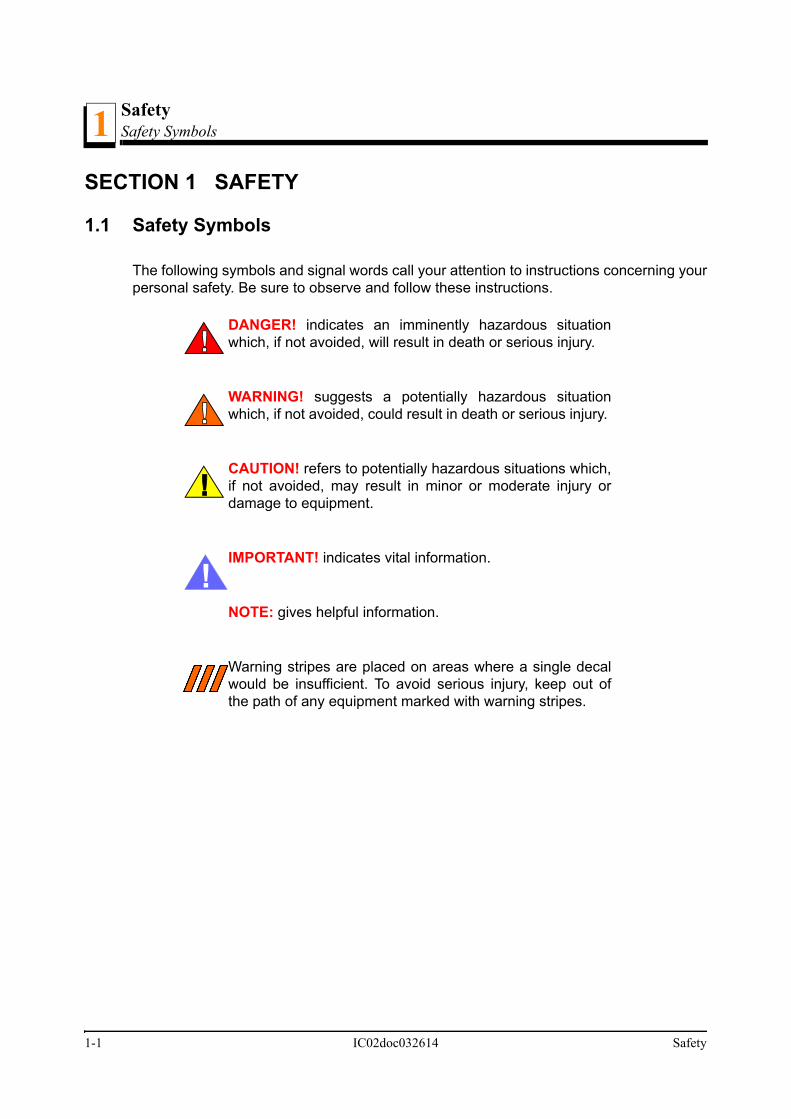
1.1 Safety Symbols
The following symbols and signal words call your attention to instructions concerning yourpersonal safety. Be sure to observe and follow these instructions.
DANGER! indicates an imminently hazardous situationwhich, if not avoided, will result in death or serious injury.
WARNING! suggests a potentially hazardous situationwhich, if not avoided, could result in death or serious injury.
CAUTION! refers to potentially hazardous situations which,if not avoided, may result in minor or moderate injury ordamage to equipment.
IMPORTANT! indicates vital information.
NOTE: gives helpful information.
Warning stripes are placed on areas where a single decalwould be insufficient. To avoid serious injury, keep out ofthe path of any equipment marked with warning stripes.
!

SafetySafety Instructions 1
1.2 Safety Instructions
NOTE: ONLY safety instructions regarding personal injury are listed in this section. Cau-tion statements regarding only equipment damage appear where applicable throughoutthe manual.
OBSERVE SAFETY INSTRUCTIONS
IMPORTANT! Read the entire Operator's Manual before operatingthe conveyor. Take notice of all safety warnings throughout thismanual and those posted on the machine. Keep this manual withthis machine at all times, regardless of ownership.
Also read any additional manufacturer’s manuals and observe anyapplicable safety instructions including dangers, warnings, andcautions.
Only persons who have read and understood the entire operator'smanual should operate the conveyor. The conveyor is not intendedfor use by or around children.
IMPORTANT! It is always the owner's responsibility to comply withall applicable federal, state and local laws, rules and regulationsregarding the ownership, operation of your Wood-Mizer products.All Wood-Mizer product owners are encouraged to become thor-oughly familiar with these applicable laws and comply with themfully while using the machine.
!
Safety IC02doc032614 1-1

SafetySafety Labels Description1
KEEP CONVEYOR AND AREA AROUND CONVEYOR CLEAN
DANGER! Maintain a clean and clear path for all necessary move-ment around the machine and lumber stacking areas. Failure to doso will result in serious injury.
CAUTIONS FOR CONVEYOR SETUP
WARNING! Securely fasten the feet of an incline conveyor to thefloor before operating the machine. Failure to do so may result inserious injury or death.
CHECK CONVEYOR BEFORE OPERATION
DANGER! Make sure all guards and covers are in place andsecured before operating the conveyor. Failure to do so may resultin serious injury.
KEEP PERSONS AWAY
WARNING! Keep all persons out of the path of movingequipment and boards while operating conveyor. Failure todo so may result in serious injury or death.
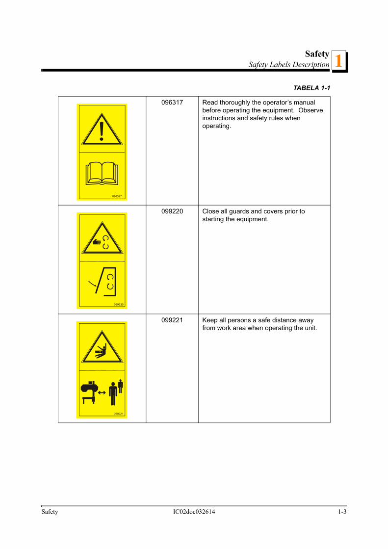
SAFETY LABELS DESCRIPTION
See Table 1-1. Pictographic safety labels are shown in the table below.
TABELA 1-1
Decal View Decal No. Description
1-2 IC02doc032614 Safety
SafetySafety Labels Description 1
096317 Read thoroughly the operator’s manual before operating the equipment. Observe instructions and safety rules when operating.
099220 Close all guards and covers prior to starting the equipment.
099221 Keep all persons a safe distance away from work area when operating the unit.
TABELA 1-1
099220
099221
Safety IC02doc032614 1-3
SafetySafety Labels Description1
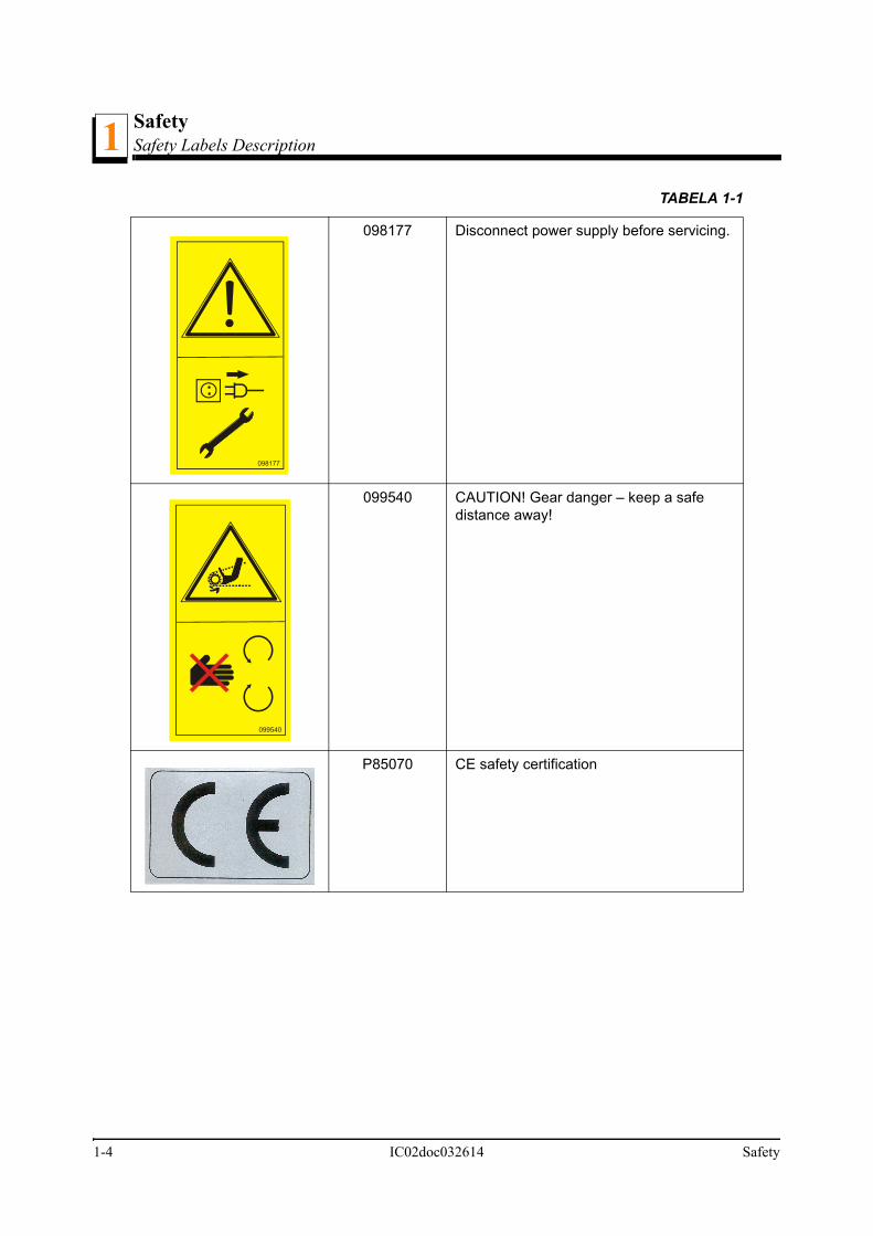
098177 Disconnect power supply before servicing.
099540 CAUTION! Gear danger – keep a safe distance away!
P85070 CE safety certification
TABELA 1-1
098177
099540
1-4 IC02doc032614 Safety

GENERAL INFORMATIONInstallation and Setup 2
SECTION 2 GENERAL INFORMATION
2.1 Installation and Setup
The Incline Conveyor allows you to quickly transport boards away from your Wood-Mizersawmill. The following manual will guide you in installation, operation, and maintenanceof the Incline Conveyor.
WARNING! Keep all persons out of the path of movingequipment and boards while operating conveyor. Failure todo so may result in serious injury or death.
See Figure 2-1. The major components of the Incline Conveyor are identified below.
See Table 2-1. See the table below for the Incline Conveyor motor specifications.
FIG. 2-1
Motor Specifications
Motor Type Electric Motor
Manufacturer
Voltage 400V 50Hz
Maximum Current 4 A
TABLE 2-1
Idle WingPulley
Conveyor Belt
Motor
Emergency StopButton
Long Leg Assembly Gearbox
Short Leg
Roller
Middle Leg Assembly
GENERAL INFORMATION ICdoc032614 2-1

GENERAL INFORMATIONInstallation and Setup2
Motor RPM
Rated Output 1,5kW ( 2HP )
Model Skh-80X-4D1
WM Part # 095064
Belt linear speed 1,3 m/s
TABLE 2-1
2-2 ICdoc032614 GENERAL INFORMATION

General InformationOverall Dimensions 2
2.2 Overall Dimensions
See Figure 2-2. The overall dimensions of the Incline Conveyor (IC1) and leg layout are
General Information ICdoc032614 2-3

General InformationOverall Dimensions2
shown below.
FIG. 2-2 INCLINE CONVEYOR (IC1)
916
1185
1302
17
85
5680
137
412
15
210
210
18
2-4 ICdoc032614 General Information

General InformationOverall Dimensions 2
See Figure 2-3. Weight are listed below.
Model Weight
IC1 700 kg
General Information ICdoc032614 2-5
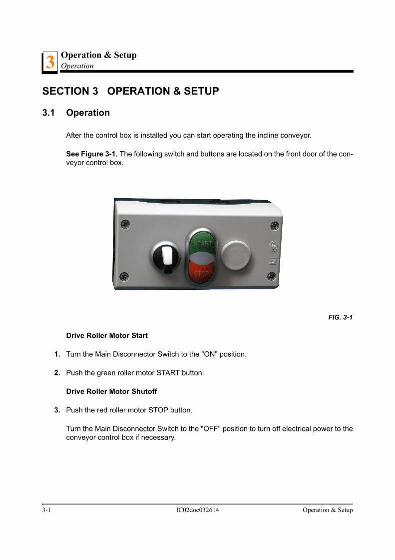
Operation & SetupOperation3
3-1 IC02doc032614 Operation & Setup
SECTION 3 OPERATION & SETUP
3.1 Operation
After the control box is installed you can start operating the incline conveyor.
See Figure 3-1. The following switch and buttons are located on the front door of the con-veyor control box.
Drive Roller Motor Start
1. Turn the Main Disconnector Switch to the "ON" position.
2. Push the green roller motor START button.
Drive Roller Motor Shutoff
3. Push the red roller motor STOP button.
Turn the Main Disconnector Switch to the "OFF" position to turn off electrical power to theconveyor control box if necessary.
FIG. 3-1

MaintenanceGearbox Oil
Maintenance IC02doc032614 4-1
4
SECTION 4 MAINTENANCE
DANGER! Always be aware of and take proper protectivemeasures against rotating shafts, pulleys, fans, etc. Alwaysstay a safe distance from rotating members and make surethat loose clothing or long hair does not engage rotatingmembers resulting in possible injury.
WARNING! Always wear proper and necessary safetyequipment when performing service functions. Propersafety equipment includes eye protection, breathing protec-tion, hand protection and foot protection.
This symbol identifies the interval (hours of operation) at which each maintenance pro-cedure should be performed. "AR" signifies maintenance procedures which should beperformed as required.
4.1 Gearbox Oil
Check the gearbox oil level. Add a synthetic gear oil such as Mobil SHC 634 as needed.
The Mobil SHC 634 gear oil is a synthesized hydrocarbon formulated used for extremelylong life. Change oil only when performing maintenance that requires gearbox disassem-bly.
If oil must be replaced, use only Mobil SHC 634.
Wood-Mizer offers replacement gear oil in 8 ounce bottles.
0
0

MaintenanceBelt Alignment4
4.2 Belt Alignment
The Incline Conveyor is factory-aligned. Periodically check and realign the conveyor beltif necessary. Make sure the belt remains centered on the drive roller and idle wing pulleywhile running. If the conveyor belt keeps travelling to the side of the drive roller and/or idlewing pulley follow the realignment procedure below.
To realign the conveyor belt:
4. Loosen the jam nuts on one or both idle wing pulley alignment bolts.
See Figure 4-1.
5. Turn one of the alignment bolts clockwise to move the idle wing pulley downward andaway from the side. Turn the alignment bolt counterclockwise to move the idle wing pulleyupward.
6. Start the drive roller motor and check if the conveyer belt still needs to be aligned. Repeatthe steps until the conveyor belt stays in place on the drive roller and idle wing pulley
FIG. 4-1
0
Loosen the jam nutto adjust the belt
Turn the adjustment boltsclockwise to move the beltaway from the side
4-1 ICdoc032614 Maintenance

MaintenanceBelt Alignment 4
while running.
7. Tighten the jam nuts when the belt alignment procedure is complete.
NOTE: You can also use the three adjustment nuts and bolts securing one side of thedrive roller bearing bracket to adjust the conveyor belt. To adjust the conveyor belt,loosen the three adjustment nuts and move the bracket to tighten or loosen the belt if nec-essary. Make sure the belt remains on the drive roller and the idle wing pulley while run-ning.
Tighten the adjustment nuts when the belt realignment procedure is complete.
Periodically check the conveyor belt for wear. Replace a damaged or worn belt asneeded. Always check the conveyor belt alignment after installing a new belt. Align theconveyor belt after replacing if necessary.
0
Maintenance ICdoc032614 4-2

MaintenanceDrive Chain Adjustment4
4.3 Drive Chain Adjustment
Periodically check the incline conveyor drive chain tension. Adjust the drive chain tensionas needed. The drive chain needs to be adjusted if the chain slack exceeds 1" (25.4mm).
DANGER! Always turn off and disconnect power supplybefore performing any service to the machine. Failure to doso may result in serious injury or death.
To check the drive chain tension, loosen the two bolts securing the drive chain front guardand remove the front guard.
See Figure 4-2.
FIG. 4-2
0
Loosen the bolts
ic0007
4-1 IC02doc032614 Maintenance

MaintenanceDrive Chain Adjustment 4
To adjust the drive chain, follow the instructions below.
1. Make sure the motor is not running.
2. Loosen the four adjustment bolts securing the conveyor gearbox to the mountmotor/gearbox bracket.
3. Move the gearbox and motor to adjust the drive chain until the center of the chain can bedeflected 1/2" (12.7mm).
See Figure 4-3.
CAUTION! Do not over-tension the conveyor drive chain.Damage to the gearbox will occur.
4. After the drive chain has been adjusted, tighten the gearbox adjustment bolts.
5. Reinstall the drive chain front guard and secure in place using the two washers and bolts.
FIG. 4-3
Loosen the adjustment boltssecuring the conveyor gearbox
Maintenance IC02doc032614 4-2

Replacement PartsIdle Side Pulley & Rollers5
SECTION 5 REPLACEMENT PARTS
5.1 Idle Side Pulley & Rollers
REF DESCRIPTION ( Indicates Parts Available In Assemblies Only) PART # QTY.
1 PULLEY, IDLE SIDE 092970-1 1
2 BOLT, M10X50-8.8 HEX HEAD FULL THREAD ZINC F81003-4 4
3 PLATE, CONVEYOR BELT TENSIONER 090854-1 2
4 BRACKET, CONVEYOR BELT TENSIONER 090853-1 2
5 BEARING, UCFL 206 CX BALL 090851 2
6 WASHER, 10.5 ZINC FLAT F81055-1 28
7 NUT, M10-8-B ZINC HEX F81033-3 12
8 PLATE, CONVEYOR BELT TENSIONER 090852-1 2
9 BOLT, M20X240-8.8 HEX HEAD FULL THREAD ZINC F81007-8 2
10 NUT, M20-8 ZINC HEX F81037-1 4
11 ROLLER, 76MM DIAMETER 090843-1 4
12 BOLT, M10x16-8.8 F81003-13 2
13 WASHER, ZINC 088059-1 2
14 GUARD, CONVEYOR BELT 096692-1 1
15 BOLT, M10X35-8.8 HEX HEAD FULL THREAT F81003-17 4
16 NUT, M10-8-B NYLON HEX ZINC LOCK F81033-1 4
17 BRACKET, COVER 2 - PTD 092419-1 4
18 COVER, CONVEYOR BELT-PTD 092423-1 1
19 BOLT, M6X20-8.8 HEX HEAD FULL THREAD ZINC F81001-2 4
IC0001_J
1
2
3
45
67
2
3
45
6
7
8
8
13
13
16
15
6
11
6
15
6
6
9
9
10
2217
1718
19
19
20
2021
2110
22
23
236
6
6 6
77
24
25
20
5-1 ICdoc032614 Replacement Parts

Replacement PartsIdle Side Pulley & Rollers 5
20 WASHER, 6.4 ZINC FLAT F81053-1 10
21 NUT, M6-8-B HEX NYLON ZINC LOCK F81031-2 4
22 TENSIONER, BELT 505831-1 2
23 Bolt, M10-1.5x25mm HH Gr8.8 F81003-11 4
24 PLATE MASKING CONVEYOR BELT IC1 511114-1 1
25 BOLT, M6 x 16 8.8 Fe/Zn5 PN-M/82105 F81001-15 2
Replacement Parts ICdoc032614 5-2

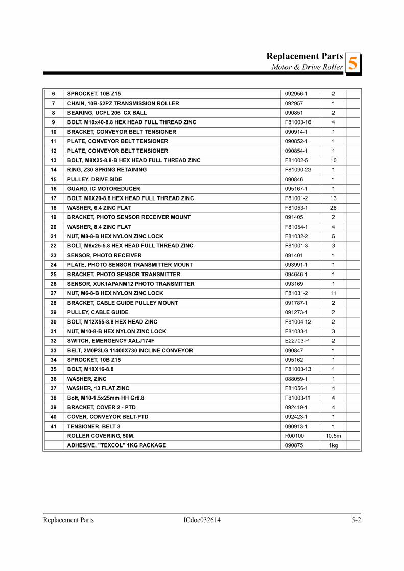
Replacement PartsMotor & Drive Roller5
5.2 Motor & Drive Roller
REF DESCRIPTION ( Indicates Parts Available In Assemblies Only) PART # QTY.
1 BRACKET, IC GEAR BOX MOUNT 090848-1 1
2 BOLT, M10x35-8.8 HEX HEAD FULL THREAD ZINC F81003-17 4
3 WASHER, 10.5 ZINC FLAT F81055-1 18
4 NUT, M10-8-B ZINC HEX F81033-3 14
5 MOTOREDUCER W/PLATE COMPLETE 503079 1
GEAR BOX, MR63/10/1,5-1400K3/N+S/B3 504859 1
MOTOR, Skh-80X-4D1 095064 1
REDUCER MR63/10/DS-160/19-WJ1/B3 083806 1
PLATE, MOTOREDUCER WITH IC1 503078-1 1
BOLT, M8X30MM, HH, GR 5.8, FULL THRD, ZINC F81002-2 4
NUT, M8-8-B HEX NYLON ZINC LOCK F81032-2 4
WASHER, 8.4 FLAT ZINC F81054-1 8
ic0016_d
1
2
3 4
55
6
7
834
9
3
1211
108
34
13
20 15
16
1718
192021
2223
13
32
29
30
31
1320
21
24
26
1817
25
28
27
27 34
14
3536
1320
33
37
3
3
18
44
17
18
18
17
18
22
27
27
18 27
27
39
38
39
40
41
5-1 ICdoc032614 Replacement Parts
Replacement PartsMotor & Drive Roller 5
6 SPROCKET, 10B Z15 092956-1 2
7 CHAIN, 10B-52PZ TRANSMISSION ROLLER 092957 1
8 BEARING, UCFL 206 CX BALL 090851 2
9 BOLT, M10x40-8.8 HEX HEAD FULL THREAD ZINC F81003-16 4
10 BRACKET, CONVEYOR BELT TENSIONER 090914-1 1
11 PLATE, CONVEYOR BELT TENSIONER 090852-1 1
12 PLATE, CONVEYOR BELT TENSIONER 090854-1 1
13 BOLT, M8X25-8.8-B HEX HEAD FULL THREAD ZINC F81002-5 10
14 RING, Z30 SPRING RETAINING F81090-23 1
15 PULLEY, DRIVE SIDE 090846 1
16 GUARD, IC MOTOREDUCER 095167-1 1
17 BOLT, M6X20-8.8 HEX HEAD FULL THREAD ZINC F81001-2 13
18 WASHER, 6.4 ZINC FLAT F81053-1 28
19 BRACKET, PHOTO SENSOR RECEIVER MOUNT 091405 2
20 WASHER, 8.4 ZINC FLAT F81054-1 4
21 NUT, M8-8-B HEX NYLON ZINC LOCK F81032-2 6
22 BOLT, M6x25-5.8 HEX HEAD FULL THREAD ZINC F81001-3 3
23 SENSOR, PHOTO RECEIVER 091401 1
24 PLATE, PHOTO SENSOR TRANSMITTER MOUNT 093991-1 1
25 BRACKET, PHOTO SENSOR TRANSMITTER 094646-1 1
26 SENSOR, XUK1APANM12 PHOTO TRANSMITTER 093169 1
27 NUT, M6-8-B HEX NYLON ZINC LOCK F81031-2 11
28 BRACKET, CABLE GUIDE PULLEY MOUNT 091787-1 2
29 PULLEY, CABLE GUIDE 091273-1 2
30 BOLT, M12X55-8.8 HEX HEAD ZINC F81004-12 2
31 NUT, M10-8-B HEX NYLON ZINC LOCK F81033-1 3
32 SWITCH, EMERGENCY XALJ174F E22703-P 2
33 BELT, 2M0P3LG 11400X730 INCLINE CONVEYOR 090847 1
34 SPROCKET, 10B Z15 095162 1
35 BOLT, M10X16-8.8 F81003-13 1
36 WASHER, ZINC 088059-1 1
37 WASHER, 13 FLAT ZINC F81056-1 4
38 Bolt, M10-1.5x25mm HH Gr8.8 F81003-11 4
39 BRACKET, COVER 2 - PTD 092419-1 4
40 COVER, CONVEYOR BELT-PTD 092423-1 1
41 TENSIONER, BELT 3 090913-1 1
ROLLER COVERING, 50M. R00100 10,5m
ADHESIVE, "TEXCOL" 1KG PACKAGE 090875 1kg
Replacement Parts ICdoc032614 5-2

Replacement PartsLegs5
5.3 Legs
REF DESCRIPTION ( Indicates Parts Available In Assemblies Only) PART # QTY.
LEG ASSEMBLY, INCLINE CONVEYOR SHORT 090876 1
1 Leg Weldment, IC Short - Upper Part 090880-1 1
LEG ASSEMBLY, INCLINE CONVEYOR MIDDLE 090881 1
2 Leg Weldment, IC Middle - Upper Part 090883-1 1
LEG ASSEMBLY, INCLINE CONVEYOR LONG 090886 1
3 Leg Weldment, IC Long - Upper Part 090885-1 1
4 LEG WELDMENT, IC - LOWER PART 512225-1 6
5 CAP, #199247 TUBE END 089644 6
6 WASHER, 20.5 ZINC SPLIT LOCK F81059-1 6
7 NUT, M20-8 ZINC HEX F81037-1 12
8 BOLT, M8X25-8.8-B HEX HEAD FULL THREAD ZINC F81002-5 24
9 WASHER, 8.4 ZINC FLAT F81054-1 48
10 NUT, M8-8-B ZINC HEX F81032-1 24
11 COVER, CONVEYOR BELT 6 -PTD 092442-1 1
12 COVER, CONVEYOR BELT 5 -PTD 092438-1 1
ic0003d
1
2
3
4
4
4
5
5
5
8
8
86
6
6
7
7
7
7
7
7
9
9
99
10
10
10
11
12
13
14
18
17
16
15
5-1 ICdoc032614 Replacement Parts

Replacement PartsLegs 5
13 COVER, CONVEYOR BELT1 4 -PTD 092445-1 1
14 COVER, CONVEYOR BELT 8 505815-1 1
15 COVER, CONVEYOR BELT 3 -PTD 092440-1 1
16 COVER, CONVEYOR BELT - PTD 092439-1 1
17 COVER, CONVEYOR BELT 6 -PTD 092437-1 1
18 COVER, CONVEYOR BELT 7 505833-1 1
Replacement Parts ICdoc032614 5-2

Replacement PartsDecals5
5-1 ICdoc032614 Replacement Parts
5.4 Decals
REF DESCRIPTION ( Indicates Parts Available In Assemblies Only) PART # QTY.
1 DECAL, SERIAL NUMBER ---------- 1
DECALS KIT, IC 503670 1
2 Decal, CE Certified Ssawmill P85070 1
3 Decal, Gear Caution 099540 1
4 Decal, Keep a Safe Distance Away 099221 1
5 Decal, Read the Operator’s Manual 096317 1
6 Decal, Disconnect Power Supply Before Servicing 098177 1
7 Decal, Close All Guards and Covers Before Starting the Machine 099220 1
123
099221
4 5
098177
6 7
099540
099220
ic_0022a

Electrical informationElectrical Symbol Diagram IC-70 6
SECTION 6 ELECTRICAL INFORMATION
6.1 Electrical Symbol Diagram IC-70
FIG. 6-1
M1
1M
23
0/4
00
V,
50
Hz
3~
L1
L2
L3
PE
U1
V1
W1
Wo
od
- M
ize
r In
du
str
ies
sp
.z.o
.o.
Ul.N
ag
órn
a 1
14
62
-600
Ko
³o ,
Po
lan
d
Pro
du
kt
Da
taR
yso
wa
³Sp
raw
dzi
³
Na
zwa
1,5
kW
-11450m
in
1M
2
13 14
3 4
1M
1
A1
A2
KK
Nu
me
r ry
s.W
ers
ja
Prz
enoœnik
taœm
ow
y d
o W
M3000
03
/08
/20
13
IC1-7
0A
Sc
he
ma
t e
lektr
yc
zny
AW
12
S1
12
S2
S1
, S
2 -
wy³¹
czn
ik a
wa
ryjn
y X
AL
K1
74
(E
22
70
3-P
) L
E1
-
rozru
szn
ik b
ezp
oœre
dn
i L
E1
M3
5Q
71
2 (
09
09
89
)
13
5
24
6
LE
1
I O/R
1 2
3 4
5 6
13 14
A1
A2
24
6
L1
L2L
3 Reset/
OR
T1
T2
T3
I O/R
1 2
3 4
5 6
13 14
A1
A2
24
6
L1
L2L
3 Reset/
OR
T1
T2
T3
12
S1
12
S2
Em
erg
ency
sw
itch
Dir
ect
star
ter
Электрическая информация ICdoc032614 6-1

Electrical InformationElectrical Symbol Diagram IC-3006
6.2 Electrical Symbol Diagram IC-300
FIG. 6-2
M6 3~
U1
V1
W1
Wo
od
- M
ize
r In
du
str
ies
sp
.z.o
.o.
Ul.N
ag
órn
a 1
14
62
-600
Ko
³o ,
Po
lan
d
Pro
du
kt
Da
taR
yso
wa
³
KK
Spra
wd
zi³
Na
zwa
Nu
me
r ry
s.W
ers
ja
Prz
en
oœn
ik t
aœm
ow
y d
o W
M3
00
00
3/0
8/2
01
3
IC1-3
00
ASc
he
ma
t e
lektr
yc
zny
1,5
kW
-11450m
in
F3/T1
F3/T2
F3/T3
177
178
12
S1
12
S2
PE
S1
, S
2 -
wy³¹
czn
ik a
wa
ryjn
y X
AL
K1
74
(E
22
70
3-P
)
AW
Em
erg
enc
y sw
itch
6-2 ICdoc032614 Electrical Information
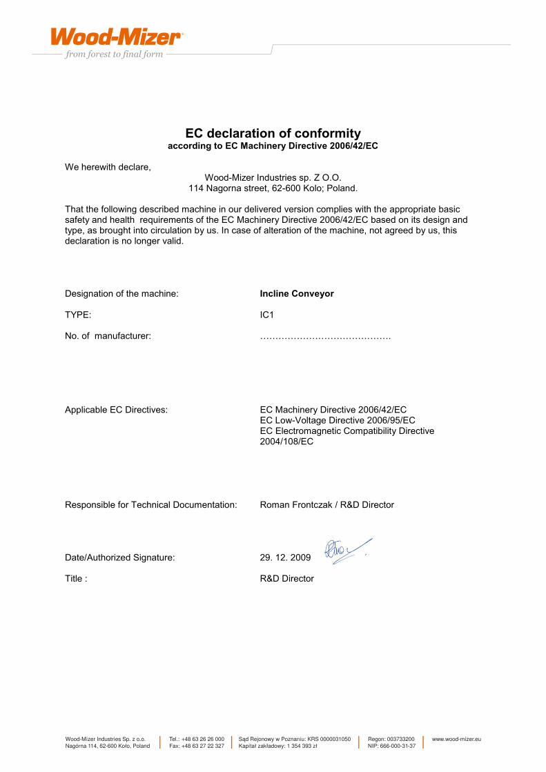
EC declaration of conformity according to EC Machinery Directive 2006/42/EC
We herewith declare,
Wood-Mizer Industries sp. Z O.O. 114 Nagorna street, 62-600 Kolo; Poland.
That the following described machine in our delivered version complies with the appropriate basic safety and health requirements of the EC Machinery Directive 2006/42/EC based on its design and type, as brought into circulation by us. In case of alteration of the machine, not agreed by us, this declaration is no longer valid. Designation of the machine: Incline Conveyor TYPE: IC1 No. of manufacturer: ……………………………………. Applicable EC Directives: EC Machinery Directive 2006/42/EC EC Low-Voltage Directive 2006/95/EC EC Electromagnetic Compatibility Directive 2004/108/EC Responsible for Technical Documentation: Roman Frontczak / R&D Director Date/Authorized Signature: 29. 12. 2009 Title : R&D Director