inchworm+ assembly instructions - dipmicro instructions ... transistors q2, q5 (bc548) ... 7...
TRANSCRIPT
< blueroomelectronics > Smart Kits build Smart People revised 12/13/2007
Page 1 of 8
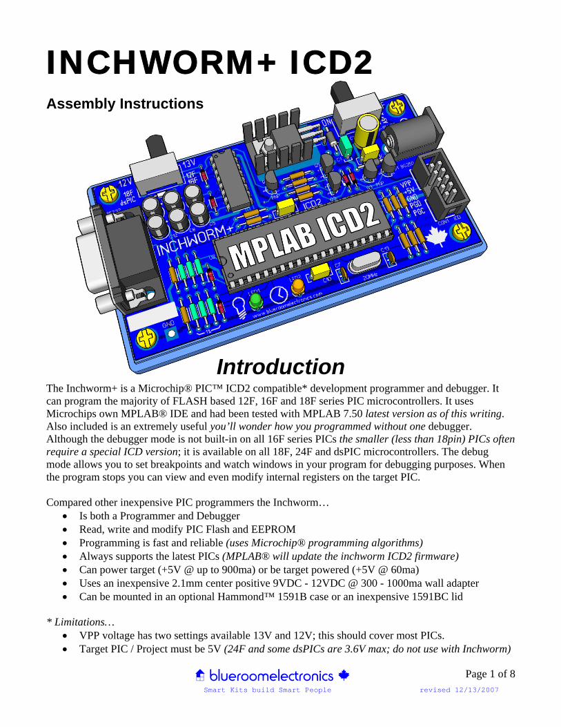
INCHWORM+ ICD2 Assembly Instructions
Introduction The Inchworm+ is a Microchip® PIC™ ICD2 compatible* development programmer and debugger. It can program the majority of FLASH based 12F, 16F and 18F series PIC microcontrollers. It uses Microchips own MPLAB® IDE and had been tested with MPLAB 7.50 latest version as of this writing. Also included is an extremely useful you’ll wonder how you programmed without one debugger. Although the debugger mode is not built-in on all 16F series PICs the smaller (less than 18pin) PICs often require a special ICD version; it is available on all 18F, 24F and dsPIC microcontrollers. The debug mode allows you to set breakpoints and watch windows in your program for debugging purposes. When the program stops you can view and even modify internal registers on the target PIC. Compared other inexpensive PIC programmers the Inchworm…
• Is both a Programmer and Debugger • Read, write and modify PIC Flash and EEPROM • Programming is fast and reliable (uses Microchip® programming algorithms) • Always supports the latest PICs (MPLAB® will update the inchworm ICD2 firmware) • Can power target (+5V @ up to 900ma) or be target powered (+5V @ 60ma) • Uses an inexpensive 2.1mm center positive 9VDC - 12VDC @ 300 - 1000ma wall adapter • Can be mounted in an optional Hammond™ 1591B case or an inexpensive 1591BC lid
* Limitations… • VPP voltage has two settings available 13V and 12V; this should cover most PICs. • Target PIC / Project must be 5V (24F and some dsPICs are 3.6V max; do not use with Inchworm)
< blueroomelectronics > Smart Kits build Smart People revised 12/13/2007
Page 2 of 8
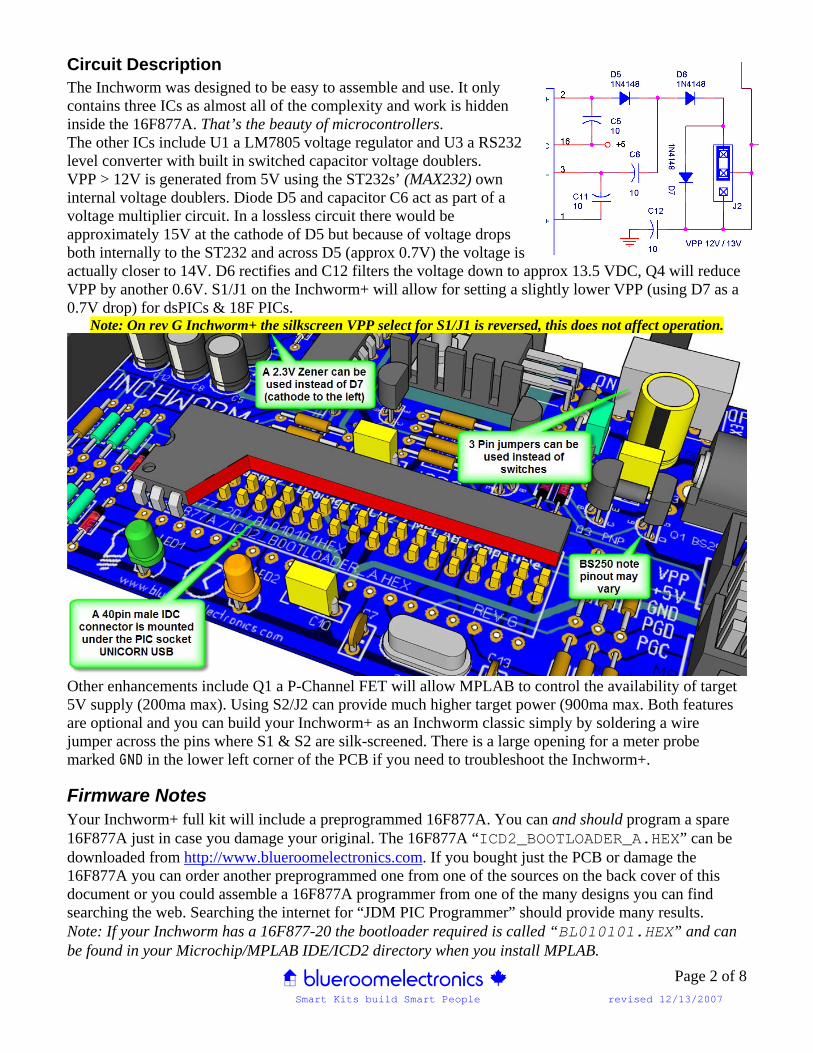
Circuit Description The Inchworm was designed to be easy to assemble and use. It only contains three ICs as almost all of the complexity and work is hidden inside the 16F877A. That’s the beauty of microcontrollers. The other ICs include U1 a LM7805 voltage regulator and U3 a RS232 level converter with built in switched capacitor voltage doublers. VPP > 12V is generated from 5V using the ST232s’ (MAX232) own internal voltage doublers. Diode D5 and capacitor C6 act as part of a voltage multiplier circuit. In a lossless circuit there would be approximately 15V at the cathode of D5 but because of voltage drops both internally to the ST232 and across D5 (approx 0.7V) the voltage is actually closer to 14V. D6 rectifies and C12 filters the voltage down to approx 13.5 VDC, Q4 will reduce VPP by another 0.6V. S1/J1 on the Inchworm+ will allow for setting a slightly lower VPP (using D7 as a 0.7V drop) for dsPICs & 18F PICs.
Note: On rev G Inchworm+ the silkscreen VPP select for S1/J1 is reversed, this does not affect operation.
Other enhancements include Q1 a P-Channel FET will allow MPLAB to control the availability of target 5V supply (200ma max). Using S2/J2 can provide much higher target power (900ma max. Both features are optional and you can build your Inchworm+ as an Inchworm classic simply by soldering a wire jumper across the pins where S1 & S2 are silk-screened. There is a large opening for a meter probe marked GND in the lower left corner of the PCB if you need to troubleshoot the Inchworm+.
Firmware Notes Your Inchworm+ full kit will include a preprogrammed 16F877A. You can and should program a spare 16F877A just in case you damage your original. The 16F877A “ICD2_BOOTLOADER_A.HEX” can be downloaded from http://www.blueroomelectronics.com. If you bought just the PCB or damage the 16F877A you can order another preprogrammed one from one of the sources on the back cover of this document or you could assemble a 16F877A programmer from one of the many designs you can find searching the web. Searching the internet for “JDM PIC Programmer” should provide many results. Note: If your Inchworm has a 16F877-20 the bootloader required is called “BL010101.HEX” and can be found in your Microchip/MPLAB IDE/ICD2 directory when you install MPLAB.

< blueroomelectronics > Smart Kits build Smart People revised 12/13/2007
Page 3 of 8
Necessary Tools (not included in kit) As with any electronic kit the following tools are essential:
• Low wattage fine tip soldering iron <50W • Resin core solder • Wire cutters or side cutters (small) • Needle nose pliers (small) • Slotted screwdriver (small) • Phillips screwdriver (small) • Multimeter (this really is a must for any electronics project)
Assembly Traditionally it’s easiest to assemble a circuit board with the lowest profile and/or smallest parts first. Install 1% (blue epoxy) resistors R3, R4, R9, R10, R17, R18 Install remaining 5% resistors (tan epoxy) Power diodes D1, D2 (Black 1N4001 or 1N5817) Small signal diodes D3 thru D9 (Red 1N4148) Note: diodes use a colored band to denote polarity *40pin IDC Male connector under U2 PIC socket IC sockets for U2 and U3 (notice notch orientation) Crystal Y1 (not too snug) and capacitors C7, 13 Transistors Q2, Q5 (BC548) / Q3, Q4 (BC558) Note: LEDs use a flat side indicating polarity LED1 (green / power), LED2 (amber / busy) Capacitors C1, C3, C9, C10 (note lead spacing) Capacitors C6, C7, C8, C9, C11, C12 (10uF) Capacitors (note polarity) C2 (47uF) Connectors CON1, CON2 (note the notch) 2 mm coax power jack P1, regulator U1 and heatsink (test fit before bending legs & soldering)
Initial Testing Before installing ICs U2 and U3 apply power to the board using a typical AC wall adapter 2.1mm ID rated between 9 – 15 VDC @ 300ma to 1000ma (Note: if you’re powering your project from the Inchworm use >500ma). The green POWER LED (pictured above) should glow. If you have a multimeter test for +5V using TP +5
Final Assembly Remove power before inserting U3 (ST232) and U2 (PIC16F877A). It is very important to insert the ICs carefully (don’t bend the pins) and in the proper direction (notice the notch on the IC). ICs inserted in the wrong direction when power is applied can damage or destroy the IC. If you’re unsure look at the main illustration on page one of this document. You’re now ready to apply power. If the POWER LED does not light immediately unplug the power and recheck that all ICs are properly inserted. If you have a multimeter you can test for >+12v using TP VPP. It’s also possible to view VDD, VPP & target VPP from MPLAB via the status option. (Note: TP VPP should not be above 15v or below 11v if it’s below 11v it’s check capacitors C4,5,6,8,11,12 and make sure they are oriented correctly and at least 16v rated). *The 40 pin IDC socket will allow for the new Unicorn USB upgrade to be attached, see previous page. Optional: The Inchworm can be mounted in a Hammond 1591B case; this will protect both the bottom of the PCB and your desk from damage.

< blueroomelectronics > Smart Kits build Smart People revised 12/13/2007
Page 4 of 8
Parts List INCHWORM+
Capacitors 1 C1 0.33uf 25V 2 C2 47uf 6.3V (thru 470uf also work) 3 C3,9,10 0.1uf 6 C4,5,6,8,11,12 10uf 16V (4.7uf also work) 2 C7,13 15pf
Resistors ¼W 5% Carbon (tan body, 4 color bands) 5 R2,5,8,11,15 330 Orange, Orange, Brown, Gold 1 R19 1K Brown, Black, Red, Gold 2 R6,7 4.7K Yellow, Green, Red, Gold 4 R1,R12,13,20 22K Red, Red, Orange, Gold 1 R14 47K Yellow, Green, Orange, Gold 1 R16 100K Brown, Black, Yellow, Gold
Resistors ¼W 1% Metal Film (blue body, 5 color bands) 2 R9,18 2.2K 1% Red, Red, Black, Brown, Brown 2 R4,10 4.7K 1% Yellow, Violet, Black, Brown, Brown 2 R3,17 6.8K 1% Blue, Gray, Black, Brown, Brown
Semiconductors 2 D1,2 1N4001 Diode (or 1N5817 if using the LM2940) 7 D3,4,5,6,7,8,9 1N4148 Diode (D7 may also be 2v Zener install reverse of 1N4148) 1 LED1 (POWER) 3mm or 5mm GREEN LED 1 LED2 (BUSY) 3mm or 5mm AMBER LED 2 Q2,5 BC548 NPN (CBE) 2 Q3,4 BC558 PNP (CBE) 1 Q1 BS250 P-FET(optional) check datasheet as pinout may vary 1 U1 LM7805 TO-220 (or LM2940-5.0 ideal for battery operation) 1 U2 PIC16F877A (preprogrammed ICD2_BOOTLOADER_A.HEX) 1 U3 ST232 (MAX232) or equivalent
Crystal 1 Y1 20MHz Crystal low profile HC49
Connectors 1 UNDERPIC 40-pin Male IDC Header 1 CON1 ICD (2x5) PCB Male 1 CON2 DE9 RA Female 2 J1,2 / S1,2 SPDT Switch (EG1224) or 3post Jumper 1 P1 2mm PCB RA Coax Jack
Miscellaneous 1 40-pin DIP IC Socket 0.6” 1 16-pin DIP IC Socket 0.3” 1 Heatsink TO-220 style approx 20mm x 14mm x 13mm 1ea Screw, Nut (for mounting LM7805 / LM2940 heatsink)
Optional Accessories 1 5-pin Berg connector or 10-pin female crimp connector 8” 10-conductor Ribbon cable 2 10-pin (2x5) IDE female crimp connectors 1 9-15VDC Adapter 9-15VDC 2.1mm center positive coax AC adapter @300-1500ma 1 Hammond 1591B Enclosure (either top or bottom will work) ** Optional add R1 & Q1 only if you want MPLAB control of target +5V ** Build Inchworm+ as a classic Inchworm, wire jumper pins over S1 & S2 omit R1,R20,Q1

< blueroomelectronics > Smart Kits build Smart People revised 12/13/2007
Page 5 of 8
< blueroomelectronics > Smart Kits build Smart People revised 12/13/2007
Page 6 of 8
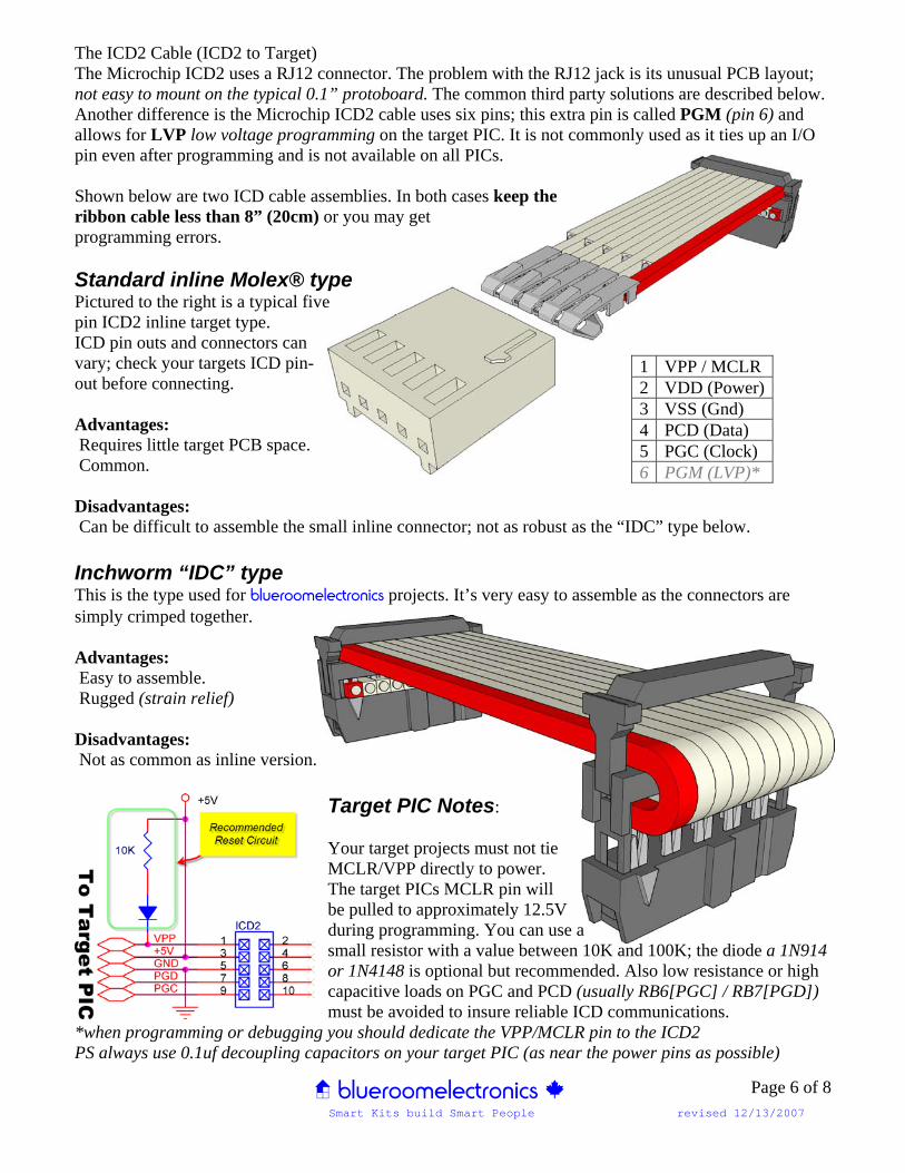
The ICD2 Cable (ICD2 to Target) The Microchip ICD2 uses a RJ12 connector. The problem with the RJ12 jack is its unusual PCB layout; not easy to mount on the typical 0.1” protoboard. The common third party solutions are described below. Another difference is the Microchip ICD2 cable uses six pins; this extra pin is called PGM (pin 6) and allows for LVP low voltage programming on the target PIC. It is not commonly used as it ties up an I/O pin even after programming and is not available on all PICs. Shown below are two ICD cable assemblies. In both cases keep the ribbon cable less than 8” (20cm) or you may get programming errors. Standard inline Molex® type Pictured to the right is a typical five pin ICD2 inline target type. ICD pin outs and connectors can vary; check your targets ICD pin- out before connecting. Advantages: Requires little target PCB space. Common. Disadvantages: Can be difficult to assemble the small inline connector; not as robust as the “IDC” type below. Inchworm “IDC” type This is the type used for blueroomelectronics projects. It’s very easy to assemble as the connectors are simply crimped together. Advantages: Easy to assemble. Rugged (strain relief) Disadvantages: Not as common as inline version.
Target PIC Notes: Your target projects must not tie MCLR/VPP directly to power. The target PICs MCLR pin will be pulled to approximately 12.5V during programming. You can use a small resistor with a value between 10K and 100K; the diode a 1N914 or 1N4148 is optional but recommended. Also low resistance or high capacitive loads on PGC and PCD (usually RB6[PGC] / RB7[PGD]) must be avoided to insure reliable ICD communications.
*when programming or debugging you should dedicate the VPP/MCLR pin to the ICD2 PS always use 0.1uf decoupling capacitors on your target PIC (as near the power pins as possible)
1 VPP / MCLR 2 VDD (Power)3 VSS (Gnd) 4 PCD (Data) 5 PGC (Clock) 6 PGM (LVP)*
< blueroomelectronics > Smart Kits build Smart People revised 12/13/2007
Page 7 of 8
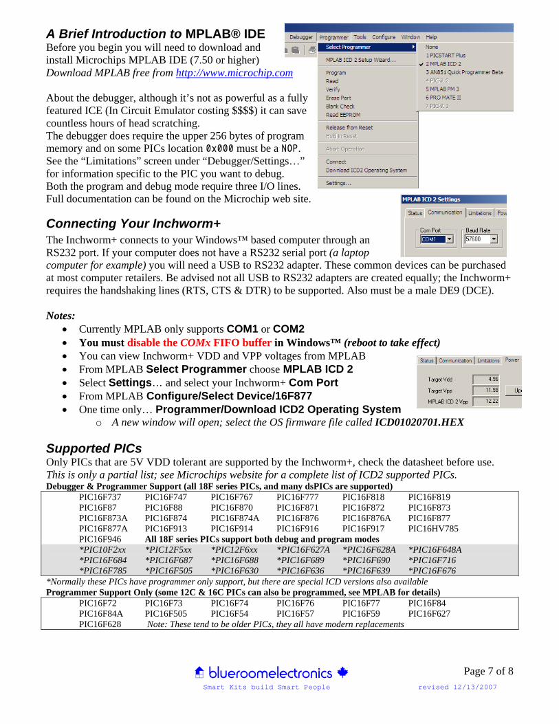
A Brief Introduction to MPLAB® IDE Before you begin you will need to download and install Microchips MPLAB IDE (7.50 or higher) Download MPLAB free from http://www.microchip.com About the debugger, although it’s not as powerful as a fully featured ICE (In Circuit Emulator costing $$$$) it can save countless hours of head scratching. The debugger does require the upper 256 bytes of program memory and on some PICs location 0x000 must be a NOP. See the “Limitations” screen under “Debugger/Settings…” for information specific to the PIC you want to debug. Both the program and debug mode require three I/O lines. Full documentation can be found on the Microchip web site.
Connecting Your Inchworm+ The Inchworm+ connects to your Windows™ based computer through an RS232 port. If your computer does not have a RS232 serial port (a laptop computer for example) you will need a USB to RS232 adapter. These common devices can be purchased at most computer retailers. Be advised not all USB to RS232 adapters are created equally; the Inchworm+ requires the handshaking lines (RTS, CTS & DTR) to be supported. Also must be a male DE9 (DCE). Notes:
• Currently MPLAB only supports COM1 or COM2 • You must disable the COMx FIFO buffer in Windows™ (reboot to take effect) • You can view Inchworm+ VDD and VPP voltages from MPLAB • From MPLAB Select Programmer choose MPLAB ICD 2 • Select Settings… and select your Inchworm+ Com Port • From MPLAB Configure/Select Device/16F877 • One time only… Programmer/Download ICD2 Operating System
o A new window will open; select the OS firmware file called ICD01020701.HEX Supported PICs Only PICs that are 5V VDD tolerant are supported by the Inchworm+, check the datasheet before use. This is only a partial list; see Microchips website for a complete list of ICD2 supported PICs. Debugger & Programmer Support (all 18F series PICs, and many dsPICs are supported)
PIC16F737 PIC16F747 PIC16F767 PIC16F777 PIC16F818 PIC16F819 PIC16F87 PIC16F88 PIC16F870 PIC16F871 PIC16F872 PIC16F873
PIC16F873A PIC16F874 PIC16F874A PIC16F876 PIC16F876A PIC16F877 PIC16F877A PIC16F913 PIC16F914 PIC16F916 PIC16F917 PIC16HV785 PIC16F946 All 18F series PICs support both debug and program modes
*PIC10F2xx *PIC12F5xx *PIC12F6xx *PIC16F627A *PIC16F628A *PIC16F648A *PIC16F684 *PIC16F687 *PIC16F688 *PIC16F689 *PIC16F690 *PIC16F716 *PIC16F785 *PIC16F505 *PIC16F630 *PIC16F636 *PIC16F639 *PIC16F676 *Normally these PICs have programmer only support, but there are special ICD versions also available Programmer Support Only (some 12C & 16C PICs can also be programmed, see MPLAB for details)
PIC16F72 PIC16F73 PIC16F74 PIC16F76 PIC16F77 PIC16F84 PIC16F84A PIC16F505 PIC16F54 PIC16F57 PIC16F59 PIC16F627 PIC16F628 Note: These tend to be older PICs, they all have modern replacements

< blueroomelectronics > Smart Kits build Smart People revised 12/13/2007
Page 8 of 8
Inchworm+ and other < blueroomelectronics > kits are available at
Retail Sales
255 College St. Toronto Ontario, Canada Tel (416) 977-9258 Fax (416) 977-4700 [email protected] http://www.creatroninc.com eBay Sales All kits available including bare PCBs
Shipping worldwide Online Sales dipmicro electronics 1251 Walkers Line, Burlington Ontario, Canada L7M4N8 Fax (866) 603-7109 http://www.dipmicro.com Dealer Sales & Technical Inquiries < blueroomelectronics > 4550 Dufferin St. Toronto Ontario, Canada Tel (416) 897-1962 [email protected] http://www.blueroomelectronics.com Info and all other inquiries [email protected]