in te r ek water & waste water treatment plant
TRANSCRIPT
L I S T E D
INTERTEK
C US
CM
Waterline Controls P.O. Box 12544 Scottsdale, Arizona 85260 • Toll Free: 888-905-1892 • Email: [email protected] • www.waterlinecontrols.com
* See Warranty for details
SC 1
Water & Waste Water Treatment Plant
SCinfo 041216
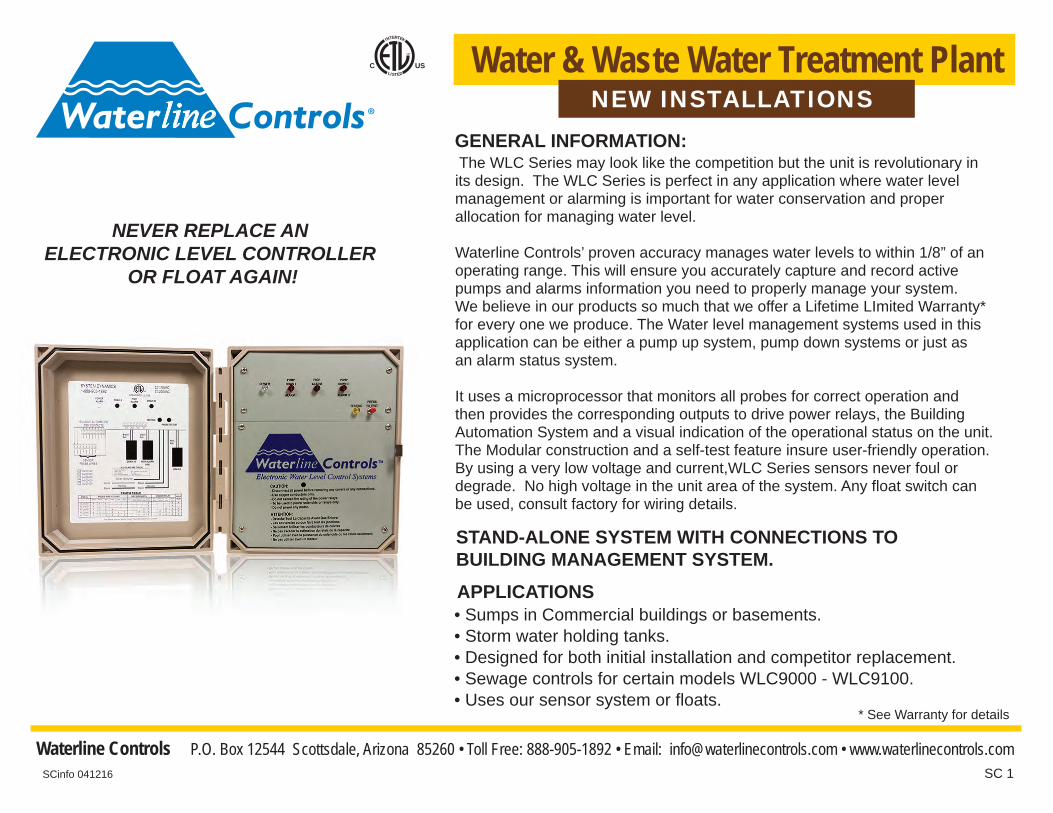
NEVER REPLACE AN ELECTRONIC LEVEL CONTROLLER
OR FLOAT AGAIN!
The WLC Series may look like the competition but the unit is revolutionary in its design. The WLC Series is perfect in any application where water level management or alarming is important for water conservation and proper allocation for managing water level. Waterline Controls’ proven accuracy manages water levels to within 1/8” of an operating range. This will ensure you accurately capture and record active pumps and alarms information you need to properly manage your system. We believe in our products so much that we offer a Lifetime LImited Warranty*for every one we produce. The Water level management systems used in this application can be either a pump up system, pump down systems or just as an alarm status system.
It uses a microprocessor that monitors all probes for correct operation and then provides the corresponding outputs to drive power relays, the Building Automation System and a visual indication of the operational status on the unit. The Modular construction and a self-test feature insure user-friendly operation. By using a very low voltage and current,WLC Series sensors never foul or degrade. No high voltage in the unit area of the system. Any float switch can be used, consult factory for wiring details.
GENERAL INFORMATION:
• Sumps in Commercial buildings or basements.• Storm water holding tanks.• Designed for both initial installation and competitor replacement.• Sewage controls for certain models WLC9000 - WLC9100.• Uses our sensor system or floats.
APPLICATIONS
STAND-ALONE SYSTEM WITH CONNECTIONS TO BUILDING MANAGEMENT SYSTEM.
NEW INSTALLATIONS

SC 2
FEATURES
COMMUNICATION WITH BUILDING MANAGEMENT
PRODUCT SPECIFICATIONS
SENSOR PROBES
MODELS
• Alarm or Pump active when water a has reached the high set point• There is improper wiring open or short
• There is power loss to the controls • High water alarm-visual & audible 102 db
Building Automation dry contacts to tell building operator when:
* See Warranty for details
• Operate on 30 VDC, 24 VAC or 110/220 VAC 50/60 Hz. specify voltage required when ordering.• Accurately manages or alarm levels to within 1/8" of operating range.
SCinfo 041216
Installations: • A licensed electrician can install the control box and sensors in less than one hour. • 110VAC Solenoid required. (We recommend any type of slow closing valve) • Sensors attach to environment wall or Sensor mounts in an external static pipe or Sensor slips into a 3" female fitting. • The sensor cable should be installed in a grounded metal conduit in order to prevent spurious signals from interfering with the sensor operation.
We make custom probes to fit any application. Any float switch can be used, consult factory for wiring. All sensor rod tips are threaded so Extension Kits can be added if needed. All other customer supplied float assemblies must be wired with shielded wire grounded to our WLC panel.
• Power relay for each function. 3 phase or single phase. All rated at 40 A resistive. • Sensor wire should not be spliced. Standard Kit has 50 ft. length. • Sensor wire available in: 50 ft., 100 ft., 150 ft., 200 ft., 250 ft., 300 ft. or longer lengths if needed.
Modular ConstructionOne-Step Internal Testing system for the electronics.Built for easy troubleshooting
Easy to install.Microprocessor controlled.Easy-to-understand LED display.
MODEL BMS DRY CONTACTS POWER RELAYSELFTEST
The Blank spaces below mean "No Connection or Function"PRODUCT FUNCTION TRUTH TABLE
FAULT ALTERNATES BEWEENPUMP 1 PUMP 2
HIGHALARM
POWERLOSS
PUMP/ALARM II
PUMP/ALARM I
PUMP/ALARM II
XX
BASWIRES
PUMP/ALARM I
BUILT-IN HIGH ALARMVISUAL & AUDIBLE
WLC7S40AWLC73P40AWLC8S40AWLC83P40AWLC9S40AWLC93P40AWLC91S40AWLC913P40A
Can use any float assembly or WLC Sensors.Lifetime Limited Warranty*
XXXXXX
XXXXXXXX
XX
XXXXXX
XXXXXXXX
XXXX
44668888
XXXX
XXXXXXXX
XXXXXXXX
XXXXXX
SINGLEPHASE
3-PHASE
X
X
X
X
X
X
X
X

SC 3
FromReservoiror Holding Tank
OPTIONS ARE: PUMP I, PUMP II & HIGH ALARM
10 WIRE DRYCONTACTSTO AUTOMATION SYSTEM
Drain to waste or other
AC Power InputPump II
High Level Alarm
All Internal Relaysare rated 30 amps at 250VAC.
Pump I
Pump Stop 1Alarm
Pump Start 1Alarm
Pump Stop 2Alarm
Pump Start 2Alarm
High Alarm
Sensor Wire
Shielded wiregrounded to aWLC unit
Can be used as Pump Start Stop or Alarm Start StopOptional: can be used for both by adding another relayto the alarm.
DIAGRAM FOR ALL MODELS
Sen
sor
Low
Vol
tage
Rac
eway
PUMPDOWN I
HIGHALARM
PUMPDOWN II
TESTINGPRESS
TO TEST
SCinfo 041216
SC 4
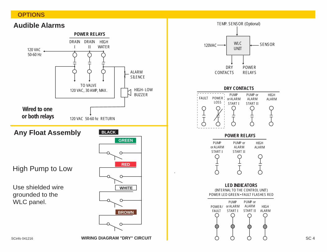
POWER RELAYSDRAIN
IDRAIN
IIHIGH
WATER120 VAC50-60 Hz
ALARMSILENCE
HIGH- LOW BUZZER
120 VAC 50-60 hz RETURN
TO VALVE120 VAC, 30 AMP, MAX.
Audible Alarms
Wired to one or both relays
Any Float Assembly
DRY CONTACTS
POWERRELAYS
WLCUNIT
120VAC SENSOR
DRY CONTACTSPUMP
or ALARMSTART I
PUMP orALARM
START II
HIGHALARM
TEMP. SENSOR (Optional)
POWER RELAYS
High Pump to Low
Use shielded wire grounded to the WLC panel.
PUMPor ALARMSTART I
PUMP orALARM
START II
HIGHALARM
WHITE
BROWN
RED
BLACK
WIRING DIAGRAM "DRY" CIRCUIT
FAULT POWERLOSS
HIGHALARM
LED INDICATORS(INTERNAL TO THE CONTROL UNIT)
POWER LED GREEN • FAULT FLASHES RED
POWER/FAULT
PUMPor ALARMSTART I
PUMP orALARM
START II
OPTIONS
GREEN
SCinfo 041216