in situ treatment performance monitoring: issues and best ... · biofouling. inspecting wells,...
TRANSCRIPT

ft EA~ United States ~ Environmental Protection "' Agency
und Water Forum Issue Paper
EPA-542-F-18-002 April 2018
In Situ Treatment Performance Monitoring: Issues and Best Practices
Index
1. INTRODUCTION ....................................................... 1
2. ISSUES RELATED TO MONITORING WELLS ......... 2
2.1 Biofouling of Monitoring Wells ............................. 2
2.2 Metal Precipitation on Monitoring Well Screens .. 3
2.3 Reactions with Well Materials and Equipment .... 4
3. REPRESENTATIVENESS OF MONITORING WELLS....................................................................... 6
3.1 Displacement of Contaminants During Amendment Injection........................................... 6
3.2 Use of Injection Wells for Monitoring ................... 7
3.3 Preferential Accumulation of Amendment in Monitoring Wells ................................................. 8
4. POST-SAMPLING ARTIFACTS ................................. 9
4.1 Post-Sampling Transformation of Contaminants . 9
4.2 Loss of Volatiles when Sampling High- Temperature Groundwater................................. 10
5. REFERENCES ........................................................ 10
6. NOTICE AND DISCLAIMER.................................... 12
7. ACKNOWLEDGMENTS .......................................... 12
APPENDIX: Quick Reference Table: In Situ Treatment Monitoring Issues and Best Practices for Monitoring, Prevention and Mitigation ................ 13
1. INTRODUCTION
The utility of monitoring wells for performance or attainment monitoring is based on the premise that contaminant concentrations measured in the wells are representative of aquifer conditions. However, during in situ treatment, various biogeochemical and hydrogeolog-ical processes and sampling and analysis procedures may affect the representativeness of the monitoring well and
sample quality, which may not be adequately considered in current remediation practice.
A properly designed monitoring network that anticipates the distribution of amendments after injection would minimize impacts to monitoring wells. However, predicting amendment distribution prior to injection is challenging such that impacts to monitoring wells are likely.
The purpose of this issue paper is to:
• describe how in situ treatment technologies may impact sampling and analysis results used to monitor treatment performance; and
• provide best practices to identify and mitigate issues that may affect sampling or analysis.
This paper discusses eight potential sampling or analytical issues associated with groundwater monitoring at sites where in situ treatment technologies are applied. These issues are grouped under three topic areas:
• Issues related to monitoring wells (Section 2).
• Representativeness of monitoring wells (Section 3).
• Post-sampling artifacts (Section 4).
The paper presents issues that pertain to collecting water samples directly from a monitoring well and does not discuss the use of other sampling techniques, such as passive diffusion bags or direct push groundwater sampling.
The in situ technologies addressed in this paper are listed in Table 1.
This issue paper does not address in situ technology selection, design or implementation, or effects resulting from combined remedies.
A quick-reference table in the Appendix can help identify potential sampling issues related to the six technologies and the best practices for monitoring or preventing and mitigating these issues.

Ground Water Forum Issue Paper2 In Situ Treatment Performance Monitoring
Table 1. In Situ Groundwater Treatment Technologies Addressed Technology Acronym General Resources
Activated Carbon-Based Injectate CBI Remediating Petroleum Contaminants with Activated Carbon-Based Injectates
Enhanced In Situ Bioremediation EISB CLU-IN Bioremediation Overview; ITRC Technical and Regulatory Requirements for Enhanced In Situ Bioreme-diation of Chlorinated Solvents in Groundwater
In Situ Chemical Oxidation ISCO CLU-IN In Situ Oxidation Overview; ITRC Technical and Regulatory Guidance for In Situ Chemical Oxidation of Contaminated Soil and Groundwater
In Situ Chemical Reduction ISCR CLU-IN In Situ Chemical Reduction technology area
In Situ Thermal Treatment ISTT CLU-IN Thermal Treatment: In Situ Overview; In Situ Thermal Treatment of Chlorinated Solvents
In Situ Solidification ISS CLU-IN Solidification Overview; ITRC Development of Performance Specifications for Solidification/Stabilization
2. ISSUES RELATED TO MONITORING WELLS
2.1 Biofouling of Monitoring Wells
2.1.1 Overview
Technologies Affected EISB ISCO CBI ISCR ISTT ISS
Mechanism – The addition of nutrients and amendments during EISB can create conditions favoring microbial growth in the vicinity of well screens and filter packs (ESTCP, 2005). Biofouling of groundwater monitoring wells occurs when enough biomass forms so that water in the well no longer represents the aquifer (Smith and Comeskey, 2009).
Impact – Biofouling of monitoring wells deposits slimes and excretions, sometimes called a biofilm, on well screens, which reduces groundwater flow into monitoring wells. Biofilms may appear as foams, pastes or gummy/slimy accumulations on well screens and sampling equipment. Figure 1 shows how a biofilm can form on an injection well screen.
Approximately 17 of 20 sites EISB surveyed reported some level of biofouling in injection wells, with most reporting at least a significant loss of injection well efficiency (ESTCP, 2005). Blocked monitoring wells and filter packs hinder sample collection or result in stagnant water in a monitoring well. Biofouling of well screens may also modify the flow of groundwater around a monitoring well and result in samples that may not be
representative of the well screen interval. In addition, biofilms may trap and degrade contaminants reducing concentrations in the well (Smith and Comeskey, 2009).
Monitoring for Biofouling – Monitoring changes in well hydraulic performance, such as reduced well production or excessive water level drawdown and physiochemical water quality parameters (e.g., dissolved oxygen [DO], oxidation-reduction potential [ORP] and specific conductivity), can provide an indication of biofouling. Inspecting wells, submerged equipment and purge water for biofouling deposits during sampling can help diagnose biofouling. Biofouling also may be observed directly using borehole video cameras. Review of the well purging history after each sampling event to identify reductions in purge rate can help identify that biofouling is occurring. Conducting slug or pumping tests periodically can provide a quantitative measure of changes over time (Barcelona et al., 1985). Limiting the potential impacts of biofouling depends on regular monitoring for these changes and promptly mitigating any problems that arise (Smith, 1995).
2.1.2 Prevention and Mitigation
Prevention of biofouling in wells used to monitor EISB performance is best achieved by understanding site hydrogeology and contaminant distribution. This site characterization information is necessary for anticipat-ing amendment distribution after injection and limiting amendment volumes to meet the site-specific electron acceptor demand (ESTCP, 2010). With this informa-tion, monitoring wells can be selected or installed so

Ground Water Forum Issue Paper 3 In Situ Treatment Performance Monitoring
-
–
–
0
1. Microorganisms attach to well screen via physical and chemical interactions
0
2. Attached microorganisms metabolize nutrients to synthesize and excrete biofilm matrix
3. Attached microorganisms multiply and obstruct screen
Figure 1. Schematic of Biofilm Formation Adapted from ESTCP, 2005.
that they are not anticipated to be influenced by the amendments or biological growth. Given that biofoul-ing often is observed during EISB, it is recommended that remedial plans include well monitoring and maintenance to identify when biofouling is occurring and have agreed-upon procedures in place for mitiga-tion. Mitigation procedures include both physical and chemical methods. Physical mitigation typically includes over-pumping, surging, jetting, or by injecting air in the casing (or vibratory methods, metal specific only). Manual brushing of well materials, followed by well redevelop-ment, can also remove material from the well screen and casing. However, brushing is not effective for cleaning filter packs (ESTCP, 2005, Smith and Comeskey, 2009). Chemical treatment with solutions of hypochlorite, hydrogen peroxide, chlorine and non-oxidizing biocides can mitigate biofouling by disinfecting the well. Chemicals are added to the well, left for varying treatment times depending on the chemical, and then surged within the well and pumped out (ESTCP, 2005). The use of chlorine will increase the concentration of chloride in groundwa-ter, which should be considered if monitoring chloride to indicate the degradation of chlorinated compounds. Chemical treatment can result in byproducts. While these byproducts are not likely to affect existing contaminants,
they may be toxic and harmful and will need to be handled carefully prior to disposal. It is important to review the available chemical treatment options to determine which is best suited for a specific site (Smith, 2011 and ESTCP, 2005). Bacteria usually regrow on the well materials in a few weeks or months after well treatment. Deeper well screens require more resources to mitigate biofouling. Mitigation of biofouling can be a significant operation and maintenance cost at sites using EISB.
Prevention and Mitigation • Limit amendment volumes to meet the site-spe
cific electron acceptor demand.
• Apply cleaning processes.
Physical processes: Surging, over-pumping, jetting, air injection.
Chemical processes: Hypochlorite, hydrogen peroxide, chlorine, non-oxidizing biocides.
2.2 Metal Precipitation on Monitoring Well Screens
2.2.1 Overview
Technologies Affected EISB ISCO CBI ISCR ISTT ISS
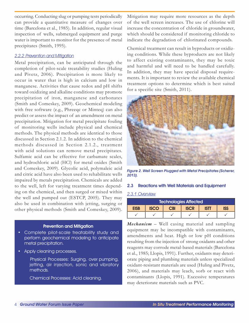
Mechanism – Changes in groundwater chemistry due to amendment introduction can cause metal precipitation on well screens (Figure 2). In situ treatments can cause changes in pH, ORP, pressure, temperature, or levels of oxygen, carbon dioxide, manganese, methane or other chemicals. These changes can cause metals in saturated groundwater solutions to change to less soluble species that precipitate.
Impact – Precipitation of metals on well screens can reduce groundwater flow into the well and potentially hinder sample collection (Huling and Pivetz, 2006), or result in stagnant water in the well.
Monitoring for Metal Precipitation on Well Screens – Monitoring changes in well hydraulic performance, such as reduced well production or excessive water level drawdown, can provide an indication of metal precipitate fouling. Review of the well purging history after each sampling event to identify reductions in purge rate can help identify that metal precipitate fouling is
Ground Water Forum Issue Paper4 In Situ Treatment Performance Monitoring
– -
–
occurring. Conducting slug or pumping tests periodically can provide a quantitative measure of changes over time (Barcelona et al., 1985). In addition, regular visual inspection of wells, submerged equipment and purge water is important to monitor for the presence of metal precipitates (Smith, 1995).
2.2.2 Prevention and Mitigation
Metal precipitation, can be anticipated through the completion of pilot-scale treatability studies (Huling and Pivetz, 2006). Precipitation is more likely to occur in water that is high in calcium and low in manganese. Activities that cause redox and pH shifts toward oxidizing and alkaline conditions may promote precipitation of iron, manganese and carbonates (Smith and Comeskey, 2009). Geochemical modeling with free software (e.g., Phreeqc or Minteq) can also predict or assess the impact of an amendment on metal precipitation. Mitigation for metal precipitate fouling of monitoring wells include physical and chemical methods. The physical methods are identical to those discussed in Section 2.1.2. In addition to the chemical methods discussed in Section 2.1.2., treatment with acid solutions can remove metal precipitates. Sulfamic acid can be effective for carbamate scales, and hydrochloric acid (HCl) for metal oxides (Smith and Comeskey, 2009). Glycolic acid, polymaleic acid and citric acid have also been used to rehabilitate wells impaired by metals precipitation. Chemicals are added to the well, left for varying treatment times depend-ing on the chemical, and then surged or mixed within the well and pumped out (ESTCP, 2005). They may also be used in combination with jetting, surging or other physical methods (Smith and Comeskey, 2009).
Prevention and Mitigation • Complete pilot-scale treatability study and
perform geochemical modeling to anticipate metal precipitation.
• Apply cleaning processes.
Physical Processes: Surging, over pumping, jetting, air injection, sonic and vibratory methods.
Chemical Processes: Acid cleaning.
Mitigation may require more resources as the depth of the well screen increases. The use of chlorine will increase the concentration of chloride in groundwater, which should be considered if monitoring chloride to indicate the degradation of chlorinated compounds.
Chemical treatment can result in byproducts or oxidiz-ing conditions. While these byproducts are not likely to affect existing contaminants, they may be toxic and harmful and will need to be handled carefully. In addition, they may have special disposal require-ments. It is important to review the available chemical treatment options to determine which is best suited for a specific site (Smith, 2011).
Figure 2. Well Screen Plugged with Metal Precipitates (Scherer, 2013).
2.3 Reactions with Well Materials and Equipment
2.3.1 Overview
Technologies Affected EISB ISCO CBI ISCR ISTT ISS
Mechanism – Well casing material and sampling equipment may be incompatible with contaminants, amendments and heat. High or low pH conditions resulting from the injection of strong oxidants and other reagents may corrode metal-based materials (Barcelona et al., 1985; Llopis, 1991). Further, oxidants may deteri-orate piping and plumbing materials unless specialized oxidant-resistant materials are used (Huling and Pivetz, 2006), and materials may leach, sorb or react with contaminants (Llopis, 1991). Excessive temperatures may deteriorate materials such as PVC.
Ground Water Forum Issue Paper 5 In Situ Treatment Performance Monitoring
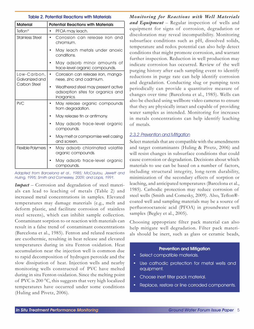
Table 2. Potential Reactions with Materials
Material Potential Reactions with Materials
Teflon® • PFOA may leach.
Stainless Steel • Corrosion can release iron and chromium.
• May leach metals under anoxic conditions.
• May adsorb minor amounts of trace-level organic compounds.
Low-Ca rbon, • Corrosion can release iron, manga-Galvanized and nese, zinc and cadmium. Carbon Steel
• Weathered steel may present active adsorption sites for organics and inorganics.
PVC • May release organic compounds from degradation.
• May release tin or antimony.
• May adsorb trace-level organic compounds.
• May melt or compromise well casing and screen.
Flexible Polymers • May adsorb chlorinated volatile organic compounds.
• May adsorb trace-level organic compounds.
Adapted from Barcelona et al., 1985; McCaulou, Jewett and Huling, 1995; Smith and Comeskey, 2009; and Llopis, 1991.
Impact – Corrosion and degradation of steel materi-als can lead to leaching of metals (Table 2) and increased metal concentrations in samples. Elevated temperatures may damage materials (e.g., melt and deform plastic, and facilitate corrosion of stainless steel screens), which can inhibit sample collection. Contaminant sorption to or reaction with materials can result in a false trend of contaminant concentrations (Barcelona et al., 1985). Fenton and related reactions are exothermic, resulting in heat release and elevated temperatures during in situ Fenton oxidation. Heat accumulation near the injection well is common due to rapid decomposition of hydrogen peroxide and the slow dissipation of heat. Injection wells and nearby monitoring wells constructed of PVC have melted during in situ Fenton oxidation. Since the melting point of PVC is 200 °C, this suggests that very high localized temperatures have occurred under some conditions (Huling and Pivetz, 2006).
Monitoring for Reactions with Well Materials and Equipment – Regular inspection of wells and equipment for signs of corrosion, degradation or discoloration may reveal incompatibility. Monitoring subsurface conditions such as pH, dissolved solids, temperature and redox potential can also help detect conditions that might promote corrosion, and warrant further inspection. Reduction in well production may indicate corrosion has occurred. Review of the well purging history after each sampling event to identify reductions in purge rate can help identify corrosion and degradation. Conducting slug or pumping tests periodically can provide a quantitative measure of changes over time (Barcelona et al., 1985). Wells can also be checked using wellbore video cameras to ensure that they are physically intact and capable of providing water samples as intended. Monitoring for increases in metals concentrations can help identify leaching of metals.
2.3.2 Prevention and Mitigation
Select materials that are compatible with the amendments and target contaminants (Huling & Pivetz, 2006) and will resist changes in subsurface conditions that could cause corrosion or degradation. Decisions about which materials to use can be based on a number of factors, including structural integrity, long-term durability, minimization of the secondary effects of sorption or leaching, and anticipated temperatures (Barcelona et al., 1985). Cathodic protection may reduce corrosion of steel wells (Smith and Comesky, 2009). Also, Teflon®-coated well and sampling materials may be a source of perfluorooctanoic acid (PFOA) in groundwater well samples (Begley et al., 2005).
Choosing appropriate filter pack material can also help mitigate well degradation. Filter pack materi-als should be inert, such as glass or ceramic beads,
Prevention and Mitigation • Select compatible materials.
• Use cathodic protection for metal wells and equipment.
• Choose inert filter pack material.
• Replace, restore or line corroded components.
Ground Water Forum Issue Paper6 In Situ Treatment Performance Monitoring
silica sand, or gravel (preferably quartz sand) that has been cleaned (Barcelona et al., 1985). If corrosion or degradation occurs, wells may be restored by adding cathodic protection, replacing the well or corroded parts, or lining corroded parts with a more compatible material (Smith and Comeskey, 2009). Monitoring wells damaged by elevated temperatures may require repair or replacement.
3. REPRESENTATIVENESS OF MONITORING WELLS
3.1 Displacement of Contaminants During Amendment Injection
3.1.1 Overview
Technologies Affected EISB ISCO CBI ISCR ISTT ISS
Mechanism – The injection of large volumes of amendment solution can potentially displace contaminated water to regions outside the treatment zone (Payne et al., 2008 and Huling and Pivetz, 2006). Displacement of contaminants can potentially occur when amendments are injected in large volumes or reactions of amendments produce large volumes of gas in the subsurface, (e.g., Fenton reagents for ISCO). In addition, increasing subsurface temperature during in situ Fenton oxidation will increase contaminant mobility and cause groundwater to volatilize and expand potentially displacing contaminants. Contaminants may move downgradient or be displaced along preferential pathways of groundwater flow.
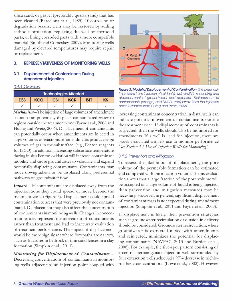
Impact – If contaminants are displaced away from the injection zone they could spread or move beyond the treatment zone (Figure 3). Displacement could spread contamination to areas that were previously not contam-inated. Displacement may also affect the concentration of contaminants in monitoring wells. Changes in concen-trations may represent the movement of contaminants rather than treatment and lead to inaccurate evaluation of treatment performance. The impact of displacement would be more significant where flowpaths are narrow, such as fractures in bedrock or thin sand lenses in a clay formation (Simpkin et al., 2011).
Monitoring for Displacement of Contaminants – Decreasing concentrations of contaminants in monitor-ing wells adjacent to an injection point coupled with
Figure 3. Model of Displacement of Contamination. The pneumat-ic pressure from injection of oxidant (blue) results in mounding and displacement of groundwater and potential displacement of contaminants (orange) and DNAPL (red) away from the injection point. Adapted from Huling and Pivetz, 2006.
increasing contaminant concentration in distal wells can indicate potential movement of contaminants outside the treatment zone. If displacement of contaminants is suspected, then the wells should also be monitored for amendments. If a well is used for injection, there are issues associated with its use to monitor performance (See Section 3.2 Use of Injection Wells for Monitoring.).
3.1.2 Prevention and Mitigation
To assess the likelihood of displacement, the pore volume of the permeable formation can be estimated and compared with the injection volume. If this evalua-tion shows that a large fraction of the pore volume will be occupied or a large volume of liquid is being injected, then prevention and mitigation measures may be necessary. However, in general, significant displacement of contaminant mass is not expected during amendment injection (Simpkin et al., 2011 and Payne et al., 2008).
If displacement is likely, then prevention strategies such as groundwater recirculation or outside-in delivery should be considered. Groundwater recirculation, where groundwater is extracted mixed with amendments and reinjected, minimizes the potential for displac-ing contaminants (NAVFAC, 2013 and Borden et al., 2008). For example, the five-spot pattern consisting of a central permanganate injection well surrounded by four extraction wells achieved a 97% decrease in trichlo-roethene concentrations (Lowe et al., 2002). However,

Ground Water Forum Issue Paper 7 In Situ Treatment Performance Monitoring
--
Ground Surface
Monitoring Wells ~ Injection Wells Monitoring Wells
Generalized Monitoring Well Network
Ext ntol Dlssolved Plume
• •
•
Prevention and Mitigation • Consider groundwater recirculation.
• Consider outside-in delivery.
• Treat areas contaminated by displacement.
recirculation systems have limitations where they may require an underground injection permit, have higher capital costs, and can be subject to fouling of injection wells (NAVFAC, 2013 and Borden et al., 2008). Using an outside-in delivery approach for amendment injections could minimize the impact from the lateral displacement of contaminants within a treatment area. With this method, injection points are located surrounding the contaminated area and amendments are injected from the outside (Huling and Pivetz, 2006). If monitoring indicates that contaminants have migrated outside the treatment zone, additional treatment and monitoring may be needed in the newly contaminated area. Mitiga-tion of displaced contamination may involve expanding the treatment zone and installing additional monitoring wells if necessary.
3.2 Use of Injection Wells for Monitoring
3.2.1 Overview
Technologies Affected EISB ISCO CBI ISCR ISTT ISS
Mechanism – After injection, amendments will likely remain in and near the injection well (Figure 4).
Impact – Samples collected from injection wells may not be representative of the site as a whole because optimal treatment performance will likely occur near the injection well (Huling and Pivetz, 2006). Contaminant concentrations in an injection well may also be biased due to displacement of contaminants by the injected amendments (See Section 3.1.).
3.2.2 Prevention and Mitigation
Remedy performance monitoring is best achieved by having a thorough understanding of site hydrogeology and contaminant distribution. This site characterization information is necessary for anticipating amendment distribution after injection and determining if an
Figure 4. Use of Separate Injection and Monitoring Wells Adapted from NAVFAC, 2013.
Figure 5. Generalized Monitoring Well Network (NJDEP, 2017).
adequate performance monitoring network exists (NJDEP, 2017). Remedy performance monitoring will require use of monitoring wells that are strategi-cally placed to determine impacts to the contaminant source area, contaminant plume and potential receptors (Figure 5). Within this context, samples from injection wells may be useful for monitoring injection constit-uents and estimating the maximum rate of contam-inant degradation (NJDEP, 2017). Although water quality samples from injection wells can be useful, they should not comprise the entire data set (Huling and Pivetz, 2006).
Prevention and Mitigation • Use a monitoring well network to determine
impacts to the contaminant source, plume, and receptors.
• Use injection wells to monitor injection constitu ents and estimate the maximum rate of contam inant degradation

Ground Water Forum Issue Paper8 In Situ Treatment Performance Monitoring
3.3 Preferential Accumulation of Amendment in Monitoring Wells
3.3.1 Overview
Technologies Affected EISB ISCO CBI ISCR ISTT ISS
Mechanism – Accumulation of amendment in monitor-ing wells may occur when they are located close to injection wells or high-pressure injection is used in low permeability formations (Figure 6). Under these circum-stances, a monitoring well is more likely to intercept injection pathways and accumulate amendments. Existing preferential pathways (e.g., utility lines) between the injection and monitoring wells can also act as conduits leading to the accumulation of amendment in monitoring wells.
Impact – The extent of amendment distribution in an aquifer may be overestimated when amendments preferentially accumulate within monitoring wells. For example, it has been suggested that high-pressure injection of powdered CBI into low-permeability formations creates random fractures, which may result in amendments accumulating in nearby monitoring wells (Figure 6). Another impact is that samples from a monitoring well containing amendment may no longer be representative of the aquifer because the contami-nant will partition to or be degraded by the amendment (See Section 4.1.). As a result, the low contaminant
Figure 6. Uneven Distribution of CBI in Clay and Sand Introduced by High-Pressure Injection.
concentration measured from the impacted well may not reflect the true extent of aquifer treatment. For example, organic contaminants are known to strongly partition from water to carbon and can also partition to the vegetable oil used for EISB (Pfeiffer et al., 2005). Another example is with in situ ozonation where ozone channels intercept monitoring wells and treat the water in the monitoring wells instead of in the aquifer (See Figure 3.).
Monitoring for Amendment Distribution – Visual inspection of samples for color, particulates or a cloudy suspension may indicate the presence of amendments. For example, a light pink to deep purple color may indicate permanganate, and black particles may indicate the presence of carbon. The emulsified oil used in EISB can accumulate in monitoring wells where it will be visible as a cloudy suspension or detected by total organic carbon and dissolved organic carbon analysis (AFCEE, 2007).
3.3.2Prevention and Mitigation
One method for minimizing amendment accumu-lation is to exercise best practices during injection. Controlling injection pressure, temperature, and flow rates can help prevent uncontrolled hydraulic fracturing (NAVFAC, 2013). The rate an aquifer can accept fluids and the lateral migration of these fluids before reaching structural failure is significantly influenced by the vertical acceptance rate (LARWQCB, 2009). Maximum injection pressure can be estimated using Equation 1 found in LARWQCB (2009) as long as the following are known: the density of the dry soil and saturated soil, the thickness of the vadose zone, and the height of the saturated zone above the injection point. When fracturing is needed in low-permeability formations, injection points should be carefully chosen to minimize potential impacts to monitoring wells. Additionally, it is important to note and consider existing preferential pathways that may impact monitoring wells.
Prevention and Mitigation • Control injection pressure, temperature, and flow
rate to prevent uncontrolled hydraulic fracturing.

Ground Water Forum Issue Paper 9 In Situ Treatment Performance Monitoring
–
–
4. POST-SAMPLING ARTIFACTS
4.1 Post-Sampling Transformation of Contaminants
4.1.1 Overview
Technologies Affected EISB ISCO CBI ISCR ISTT ISS
Mechanism – Organic contaminants and amendments can be commingled in groundwater samples collected from sites where amendments have been injected, resulting in contaminants being transformed in the time between sample collection and analysis (Ko, Huling and Pivetz, 2012). Examples of amendments that may persist in samples include oxidants, such as permanganate for ISCO, or reductants such as micron or nano zero valent iron for ISCR. In addition, microbes contained in groundwater samples may continue to degrade contaminants between sample collection and analysis, particularly when amendments have been added for EISB. Changes in ORP between the aquifer and sample bottle may also facilitate chemical transformation.
Impact – If amendment is present and abiotic or biotic degradation is possible, and the samples are not preserved correctly, the results may indicate lower concentrations of contaminants than are actually present in the groundwater (Ko, Huling and Pivetz, 2012).
Monitoring for Post-Sampling Transformations of Contaminants – Post-sampling transformation can be monitored by checking for the presence of oxidative or reductive amendments in the sample. Groundwater samples can be collected and analyzed in the field specif-ically to determine the presence of these amendments. If the groundwater sample contains both amendments and organic contamination, then there is a high risk of contaminant transformation. Field tests for permanga-nate and persulfate oxidants include colorimetry test kits and field-based spectrophotometric analysis (Ko, Huling and Pivetz, 2012).
4.1.2 Prevention and Mitigation
Mitigation can be done by ensuring that the correct sample preservation and quenching procedures are used (Table 3). For ISCO applications, proper sample handling and preser-vation depend on the oxidant being used (Huling and Pivetz, 2006). In the case of permanganate and persulfate,
Prevention and Mitigation • Preserve samples.
Neutralize amendments.
Cool samples.
• Allow sufficient time for amendments to fully react before taking samples for performance monitoring.
ascorbic acid can be added to the groundwater sample in order to neutralize the oxidant and reduce the impact of the oxidant on sample results (Ko, Huling and Pivetz, 2012). Recommendations for preservative amounts can be found in references such as Ko, Huling and Pivetz, 2012. Notify-ing the analytical laboratory that the aqueous samples may contain residual persulfate or permanganate, and the volume of preservative solution added to the sample will allow the lab to correct for dilutions. Other preservatives have been used to successfully neutralize these oxidants but may negatively impact the quality of the sample (Huling, Ko and Pivetz, 2011). Applications using ozone or Fenton’s reagent typically do not require preservation to prevent post-sampling oxidative transformation because of their short persistence. In lieu of preservation, delaying sampling until the oxidant has been fully consumed and is no longer detected in screening samples minimizes post-sampling transformation. However, permanganate may persist for long periods and, therefore, may require neutralization prior to complete reaction (Huling and Pivetz, 2006).
Table 3. Persistence and Preservatives for Common Oxidants
Oxidant Persistence Preservative
Permanganate >3 months Ascorbic acid
Persulfate Hours - weeks Ascorbic acid
Ozone Minutes - hours Not applicable
Fenton’s reagent Minutes - hours Not applicable
Adapted from Huling and Pivetz, 2006 and Ko, Huling and Pivetz, 2012.
Methods for eliminating or slowing biodegradation in samples with volatile organics include cooling to between 0 and 6 °C and adjusting the pH to less than 2 (U.S. EPA, 2016). For fuel oxygenates, base may be added to samples to prevent biodegradation and minimize ether hydrolysis (U.S. EPA, 2003).

Ground Water Forum Issue Paper10 In Situ Treatment Performance Monitoring
~ ---
4.2 Loss of Volatiles when Sampling High-Temperature Groundwater
4.2.1 Overview
Technologies Affected EISB ISCO CBI ISCR ISTT ISS
Mechanism – Where remedy application results in elevated temperature, it may trigger a phase change from liquid to gas for volatile contaminants. Volatile compounds may escape from the sample, resulting in contaminant losses, especially where groundwater samples are exposed to the atmosphere (USACE, 1998). ISTT heats the subsurface and increases sample temperatures, which may result in loss of volatiles. Technologies that cause exothermic reactions, such as ISCO and ISS, can also heat the subsur-face and lead to a loss of volatile contaminates during sample collection. High temperatures may also cause contaminants to react after sampling.
Impact – Volatilization and reactions of contaminants from samples could result in an underestimate of contaminant concentrations (USACE, 2014).
4.2.2 Prevention and Mitigation
Evaluation of contaminant volatility at elevated temperatures can inform approaches to prevent or mitigate potential sampling or analytical issues associ-ated with loss of volatiles.
Mitigation can involve using dedicated sampling ports or taps that can be accessed without opening the monitoring well cap (USACE, 2014). Groundwater extracted from the well should flow through a cooling coil to decrease the groundwater temperature before the sampling point (USACE, 2014). In addition, submerging samples in an ice bath immediately after collection and keeping them cool until analysis can reduce loss of volatiles (USACE, 2014).
If dedicated sampling ports are not available, then waiting until the subsurface has cooled before sampling may be necessary.
Prevention and Mitigation • Use dedicated sampling ports and cooling coil
to decease groundwater temperature before sample collection.
• Allow subsurface temperature to cool before sampling for performance monitoring.
5. REFERENCES
Air Force Center for Engineering and the Environment (AFCEE). 2007. Protocol for In Situ Bioremediation of Chlorinated Solvents Using Edible Oil. https://clu-in. org/download/remed/Final-Edible-Oil-Protocol-Oc-tober-2007.pdf
Barcelona, M.J., Gibb, J.P., Helfrich, J.A. and Garske, E.E. 1985. Practical Guide for Ground-Water Sampling. Illinois State Water Survey, ISWS Contract Report 374. http://www.orau.org/ptp/PTP%20Library/library/ epa/samplings/pracgw.pdf
Begley, T.H., White, K., Honigfort, P., Twaroski, M. L., Neches, R. and Walker., R. A. 2005. Perfluorochemicals: Potential sources of and migration from food packaging. Food Additives and Contaminants 22(10):1023–1031. https://www.ncbi.nlm.nih.gov/pubmed/16227186
Borden, R., Clayton, M., Simking, T., Lieberman M.T. and Weispfenning, A. 2008. Development of a Design Tool for Planning Aqueous Amendment Injection Systems Emulsion Design Tool. ESTCP Project ER-20062. June. https://clu-in.org/download/contam-inantfocus/tce/ER-0626-Emulsion-design-tool.pdf
Department of Defense Environmental Security Technology Certification Program (ESTCP). 2005. A Review of Biofouling Controls for Enhanced In Situ Bioremediation of Groundwater. October. Click Download Technical Report. https://www.serdp-es-tcp.org/Program-Areas/Environmental-Restoration/ Contaminated-Groundwater/ER-200429/ER-200429/ (language)/eng-US)
Fox, T. and Winner, E. 2016. Lessons Learned and Paths to Success with Activated Carbon Injections. In ASTSWMO Workshop, Pittsburgh, PA. April. http:// astswmo.org/files/Meetings/2016/MYM/presenta-tions/2016-04-28-LUST-1030am/Winner_Fox.pdf.
Huling, S.G. and B.E. Pivetz. 2006. In-Situ Chemical Oxidation. EPA Office of Research and Develop-ment, EPA/600/R-06/072. August. http://nepis. epa.gov/Exe/ZyPDF.cgi/2000ZXNC.PDF?Dock-ey=2000ZXNC.PDF
Huling, S.G., Ko, S. and Pivetz, B. 2011. Groundwater Sampling at ISCO Sites: Binary Mixtures of Volatile Organic Compounds and Persulfate. Groundwa-

Ground Water Forum Issue Paper 11 In Situ Treatment Performance Monitoring
ter Monitoring & Remediation. Volume 31, Issue 2. Pages 72-79. Spring. http://onlinelibrary.wiley.com/ doi/10.1111/j.1745-6592.2011.01332.x/abstract
Ko, S. Huling, S.G. and Pivetz, B. 2012. Ground Water Sample Preservation at In-Situ Chemical Oxidation Sites – Recommended Guidelines. EPA National Risk Management Research Laboratory. EPA/600/R-12/049. August. https://www.epa.gov/sites/production/ files/2015-06/documents/isco_gw_sampling_issue_ paper.pdf
Llopis, J.L. 1991. The Effects of Well Casing Material on Ground Water Quality. Office of Solid Waste and Emergency Management. EPA/540/4-91/005. October. https://nepis.epa.gov/Exe/ZyPDF.cgi/40001I6P. PDF?Dockey=40001I6P.PDF
Los Angeles Regional Water Quality Control Board (LARWQB). 2009. Technical Report: Subsurface Injection of In Situ Remedial Reagents (ISRRs) Within the Los Angeles Regional Water Quality Control Board Jurisdiction. https://www.waterboards.ca.gov/losange-les/water_issues/programs/ust/guidelines/Subsur-face_injection_of_ISRR.pdf
Lowe, K.S., Garder, F.G. and Siegrist, R.L. 2002. Field Evaluation of In Situ Chemical Oxidation Through Vertical Well-to-Well Recirculation of NaMnO4. Groundwater Monitoring and Remedia-tion 22(1): 106-115. http://onlinelibrary.wiley.com/ doi/10.1111/j.1745-6592.2002.tb00659.x/full
McCaulou, D.R., Jewett, D.G. and Huling, S.G. 1995. Nonaqueous Phase Liquids Compatibility with Materials Used in Well Construction, Sampling, and Remediation. EPA/540/S-95/503. July. https://www.epa.gov/sites/ production/files/2015-06/documents/napl.pdf
Naval Facilities Engineering Command (NAVFAC). 2013. Best Practices for Injection and Distribution of Amendments. TR-NAVFAC-EXWC-EV-1303. March. https://clu-in.org/download/techfocus/chemox/ Inject-amend-tr-navfac-exwc-ev-1303.pdf
New Jersey Department of Environmental Protection (NJDEP). 2017. In Situ Remediation: Design Consider-ations and Performance Monitoring Technical Guidance Document. October, Version 1.0. http://www.nj.gov/ dep/srp/guidance/srra/in_situ_remediation.pdf ?ver-sion_1_0
Payne, F.C., Quinnan, J.A. and Potter, S.T. 2008. Displacement concepts. In Remediation Hydraulics, 332-336. CRC Press. https://www.crcpress.com/ Remediation-Hydraulics/Payne-Quinnan-Potter/p/ book/9780849372490
Pfeiffer, P., Bielefeldt, A.R., Illangasekare, T. and Henry, B. 2005. Partitioning of dissolved chlorinated ethenes into vegetable oil. Water Research 39: 4521-4527.
Scherer, T. 2013. Care and Maintenance of Irrigation Wells. North Dakota State University. AE-97 (Revised). May. https://www.ag.ndsu.edu/publications/crops/ care-and-maintenance-of-irrigation-wells
Simpkin, T.J., Palaia, T., Petri, B.G. and Smith, B.A.. 2011. Oxidant Delivery Approaches and Contingency Planning. In Situ Chemical Oxidation for Groundwater Remediation, 449-480. Springer. https://link.springer. com/chapter/10.1007/978-1-4419-7826-4_11
Smith, S.A. 1995. Monitoring and Remediation Wells: Problem Prevention, Maintenance, and Rehabilitation. CRC Press. May 4. https://www.crcpress.com/Monitor-ing-and-Remediation-Wells-Problem-Prevention-Main-tenance-and/Smith/p/book/9780873715621
Smith, S.A. and Comeskey, A.E. 2009. Sustainable Wells: Maintenance, Problem Prevention, and Rehabil-itation. CRC Press. November 4. https://www.crcpress. com/Sustainable-Wells-Maintenance-Problem-Pre-vention-and-Rehabilitation/Smith-Comeskey/p/ book/9780849375767
Smith, S.A. 2011. Primer on Microbial Problems in Water Wells. June 27. http://www.groundwaterscience. com/resources/tech-article-library/96-primer-on-mi-crobial-problems-in-water-wells.html
U.S. Army Corps of Engineers (USACE). 1998. USACE Sample Collection and Preparation Strategies for Volatile Organic Compounds in Solids. October. https://clu-in. org/download/stats/sampling.pdf
U.S. Army Corps of Engineers (USACE). 2014. Section 8.1.5.1 Liquid. In Design: In Situ Thermal Remedi-ation. USACE EM 200-1-21. May 30. http://www. publications.usace.army.mil/Portals/76/Publications/ EngineerManuals/EM_200-1-21.pdf ?ver=2014-05-08-155746-393

Ground Water Forum Issue Paper12 In Situ Treatment Performance Monitoring
United States Environmental Protection Agency (U.S. EPA). 2003. Underground Storage Tanks Fact Sheet, Analytical Methodologies for Fuel Oxygenates. EPA-510-F-03-001. April. https://nepis.epa.gov/Exe/ ZyPDF.cgi/2000D90Y.PDF?Dockey=2000D90Y.PDF
United States Environmental Protection Agency (U.S. EPA). 2009. Industrial Stormwater Monitoring and Sampling Guide. EPA 832-B-09-003. March. https:// www3.epa.gov/npdes/pubs/msgp_monitoring_guide.pdf
United States Environmental Protection Agency (U.S. EPA). 2016. Chapter 4, The SW-846 Compendium. https://www.epa.gov/hw-sw846/sw-846-compendium
6. NOTICE AND DISCLAIMER
This paper was prepared for the EPA Office of Superfund Remediation and Technology Innovation (OSRTI), Technology Innovation and Field Services Division and the Ground Water Forum, a component
of the U.S. EPA Superfund Technical Support Project, under EPA Contract Number EP-W-14-001. This information has received technical EPA review and does not necessarily reflect the views of EPA or other participating organizations, and no official endorsement should be inferred. The information is not intended, nor can it be relied upon, to create any rights enforceable by any party in litigation with the United States or any other party. Use or mention of trade names does not constitute an endorsement or recommendation for use.
A PDF version of Ground Water Forum Issue Paper : In Situ Treatment Monitoring Issues and Best Practices is available to view or download at https://www.epa.gov/remedy-tech/technical-support-project-cleaning-contaminat-ed-sites-issue-papers and http://www.cluin.org.
7. ACKNOWLEDGMENTS
OSRTI and the Ground Water Forum thank all the EPA staff involved in the development of this document.

Ground Water Forum Issue Paper 13 In Situ Treatment Performance Monitoring
APPENDIX: Quick Reference Table: In Situ Treatment Monitoring Issues and Best Practices for Monitoring, Prevention and Mitigation
Potential Sampling Issue Technology Best Practices
EISB ISCO CBI ISCR ISTT ISS
Issues Related to Monitoring Wells
Biofouling of monitoring wells Monitoring • Mechanism: Enhanced • Monitor changes in well hydraulic perfor-
microbial activity leads to mance, such as reduced well produc-growth of biomass on well tion. screen and in filter pack.
• Inspect monitoring wells, submerged • Impact: Impedes ground- equipment and purge water for signs of
water entry to well, poten- biofouling. t ial ly hindering sample Prevention and Mitigation collection or resulting in stagnant water in wel l. Changes groundwater flow
• Limit amendment volumes to meet the site-specific electron acceptor demand.
around well and adsorption • Apply cleaning processes followed by or degradation of contami- well redevelopment: nants, potentially resulting in samples not representative of aquifer.
– Physical processes: surging, over-pump-ing, brushing, jetting or air injection.
– Chemical processes: cleaning with hypochlorite, hydrogen perox-ide, chlorine (will increase chloride in groundwater) or non-oxidizing biocides.
Metals precipitation on Monitoring monitoring well screens • Monitor changes in well hydraulic perfor-• Mechanism: Change in mance, such as reduced well production.
groundwater chemistry due to addition of amendments can cause metal precip-itation on monitoring well
• Inspect monitoring wells, submerged equipment and purge water during sampling for signs of precipitates.
screens. Prevention and Mitigation
• Impact: Damages or fouls we l l sc reen impeding groundwater entry. Potential-
• Complete pilot-scale treatability study and perform geochemical modeling to anticipate metal precipitation.
ly hinders sample collection • Apply cleaning processes followed by or results in stagnant water in well redevelopment: well that is not representative of the aquifer. – Physical processes: surging, over-pump-
ing, jetting, air injection, sonic or vibra-tory methods.
– Chemical processes: acid cleaning.

Ground Water Forum Issue Paper14 In Situ Treatment Performance Monitoring
Potential Sampling Issue Technology Best Practices
EISB ISCO CBI ISCR ISTT ISS
Reactions with well materials Monitoring and equipment • Monitor changes in well hydraulic perfor-• Mechanism: Well casing mance, such as reduced well production.
material and sampling equipment incompatible with contaminants, amend-ments and heat may cause corrosion or deterioration of
• Inspect monitoring wells, submerged equipment, and purge water during sampling for signs of corrosion or degra-dation.
casing or equipment. Prevention and Mitigation
• Impact: May hinder sample • Select compatible materials.
collection or foster adsorp- • Use cathodic protection for metal wells tion or desorption of contam- and equipment. inants, resulting in samples not representative of the • Choose inert filter pack material.
aquifer. • Replace, restore or line corroded compo-nents.
Representativeness of Monitoring Wells
Displacement of Monitoring contaminants during • Monitor wells adjacent to or downgra-amendment injection dient from injection wells for increasing • Mechanism: Injection of contaminant concentrations.
large volumes of amend- Prevention and Mitigation ments or react ions of amendments that produce • Consider groundwater recirculation.
large volumes of gas can • Consider outside-in delivery. displace contaminated groundwater. • Treat areas contaminated by displace-
ment. • Impact: Displaces contami-
nated groundwater, possibly to uncontaminated areas. May yield non-representative sampling results if sampling is limited to original area of contamination.
Use of injection wells for Prevention and Mitigation performance monitoring • Use monitoring well network to determine • Mechanism: Amendments impacts to contaminant source, plume
will likely remain in and near and receptors. the injection well.
• Use injection wells to monitor injection • Impact: Samples collected constituents and estimate maximum rate
from injection wells may not of contaminant degradation. be representative of the site as a whole because optimal treatment performance will likely occur near the injec-tion well.

Ground Water Forum Issue Paper 15 In Situ Treatment Performance Monitoring
Potential Sampling Issue Technology Best Practices
EISB ISCO CBI ISCR ISTT ISS
Preferential accumulation of amendment in monitoring wells • Mechanism: Injection of
amendments near monitor-ing wells or use of high-pres-sure injection.
• Impact: Causes hydrau-lic fracturing that creates pathways for amendment to flow to wells. Results in
Monitoring • Visually observe amendments in monitor-
ing wells for color, particulates or cloudy suspension.
• Analyze total organic carbon or dissolved organic carbon for EISB amendments.
Prevention and Mitigation • Control injection pressure, temperature
and flow rate to prevent uncontrolled hydraulic fracturing.
overestimate of distribu-tion of amendments. Also, contaminant concentra-tions in wells no longer repre-sent treatment zone.
Post-Sampling Artifacts
Post sampling transformation Monitoring of contaminants • Monitor presence of amendment and/ • Mechan i sm: A mend - or microbes.
ments and microbes are Prevention and Mitigation commingled in groundwa-ter samples. • Preserve samples.
• Impact: Transforms contam- – Neutralize amendments.
inants after collection but – Cool samples. prior to analysis, resulting in unrepresentative samples. • Allow sufficient time for amendments
to fully react before taking samples for performance monitoring.
Loss of volatiles when sampling high-temperature groundwater • Mechanism: Increased
temperature of groundwa-
Monitoring • Evaluate contaminant volatility.
• Monitor groundwater temperature during all stages of sample collection.
ter samples through appli-cation of in situ thermal or chemical technologies that result in elevated tempera-tures.
• Impact: Potential loss of volatile contaminants during sample collection, resulting in samples not representa-tive of aquifer.
Prevention and Mitigation • Use dedicated sampling ports and a
cooling coil to decrease groundwater temperature before sample collection.
• Allow subsurface temperatures to cool before collecting samples.