in-situ thermal treatment of trichloroethene at marshall ... · in-situ thermal treatment of...
TRANSCRIPT

In-situ Thermal Treatment of Trichloroethene
at
Marshall Space Flight CenterJason Cole, William J. McElroy, Jason Glasgow (CH2M HILL, Inc.)Gorm
Heron, Jim Galligan, and Ken Parker (TerraTherm, Inc., Fitchburg, MA)E.F. Davis (NASA Marshall Space Flight Center, Huntsville, AL)
https://ntrs.nasa.gov/search.jsp?R=20080032806 2018-06-02T04:10:19+00:00Z

Background 1•
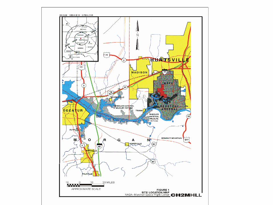
Marshall Space Flight Center (MSFC) is the principle propulsion development center for the National Aeronautics and Space Administration (NASA).
–
Located in Huntsville, Alabama MSFC covers ~1,800 acres within the boundary of Redstone Arsenal (U.S. Army).
–
79 sites regulated under the Comprehensive Environmental Resource Conservation and Liability Act (CERCLA).
–
Groundwater has been integrated into one operable unit (OU-3)
•
Groundwater Strategy–
Identify contaminant sources, contributing sites or activities; –
Characterize major groundwater plumes;–
Eliminate / Reduce Source Areas; and–
Monitor to verify treatment effectiveness and continued compliance with regulatory framework.
•
[REFERENCE GRAPHIC LOCATOR MAPS]

Background 2•
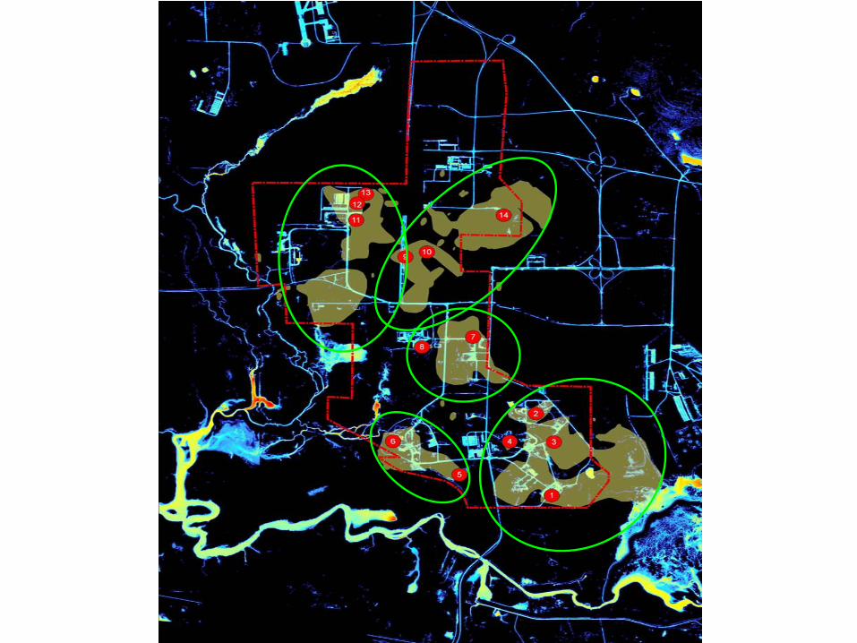
Five major groundwater plumes and 15 “hot spots”
have been identified
•
Chlorinated solvents are the dominant contaminants site wide; trichloroethylene (TCE) is the most abundant and widespread
•
Treatability
study program initiated to:–
assess degree of in-situ technology effectiveness–
reduce uncertainties in future OU-3 feasibility study•
Study area selection:–
Screen source area contaminants –
Identify potentially applicable in-situ treatment technologies–
Develop numeric ranking to select study areas and technologies
•
[REFERENCE THERMAL IMMAGRY]

Source Area -13•
Source Area-13 (SA-13) was one of four study areas selected.•
SA-13 history and investigation results indicate that a former drum
storage pad area outside of building 4705 was the likely source area of contaminants. –
TCE is the primary soil and groundwater contaminant–
Presence of dense non-aqueous phase liquid (DNAPL) suspected:–
TCE soil concentrations ≥
260 mg/kg and groundwater ≥
11,000 µg/l
•
In-situ technologies selected for evaluation:–
In-situ chemical oxidation (ISCO) –
In-situ Thermal Treatment (ISTT)
•
Treatment at SA-13 by ISCO had limited effectiveness.•
On the basis of the ISCO results, NASA made the decision to evaluate ISTT at SA-13.
•
[REFERENCE CONCEPTUAL SITE MODEL AND PLAN VIEW MAP]
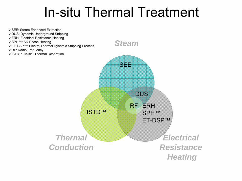
In-situ Thermal Treatment
Steam
Electrical Resistance
Heating
ThermalConduction
DUS
ERHSPH™ET-DSP™
SEE
RFISTD™
SEE: Steam Enhanced ExtractionDUS: Dynamic Underground StrippingERH: Electrical Resistance HeatingSPH™: Six Phase HeatingET-DSP™: Electro-Thermal Dynamic Stripping ProcessRF: Radio Frequency ISTD™: In-situ Thermal Desorption

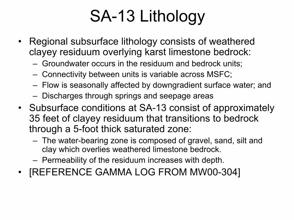
SA-13 Lithology•
Regional subsurface lithology
consists of weathered
clayey residuum overlying karst
limestone bedrock:–
Groundwater occurs in the residuum and bedrock units;–
Connectivity between units is variable across MSFC; –
Flow is seasonally affected by downgradient
surface water; and–
Discharges through springs and seepage areas•
Subsurface conditions at SA-13 consist of approximately 35 feet of clayey residuum that transitions to bedrock through a 5-foot thick saturated zone:–
The water-bearing zone is composed of gravel, sand, silt and clay which overlies weathered limestone bedrock.
–
Permeability of the residuum increases with depth.•
[REFERENCE GAMMA LOG FROM MW00-304]
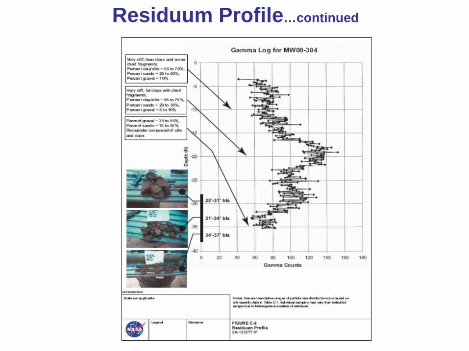
Residuum Profile…continued

SA-13 In-Situ Thermal TS
•
Implement ISTT in “hot spot”
of source area to assess technology treatment capability
•
In-situ Thermal Desorption (ISTD) process was selected for ISTT demonstration
•
ISTD process originally developed by SHELL and licensed to TerraTherm®–
electrical subsurface heating by thermal conduction
–
concurrent extraction of vapor and groundwater–
ex-situ treatment of extracted fluids
•
[Reference ISTD FIGURES]
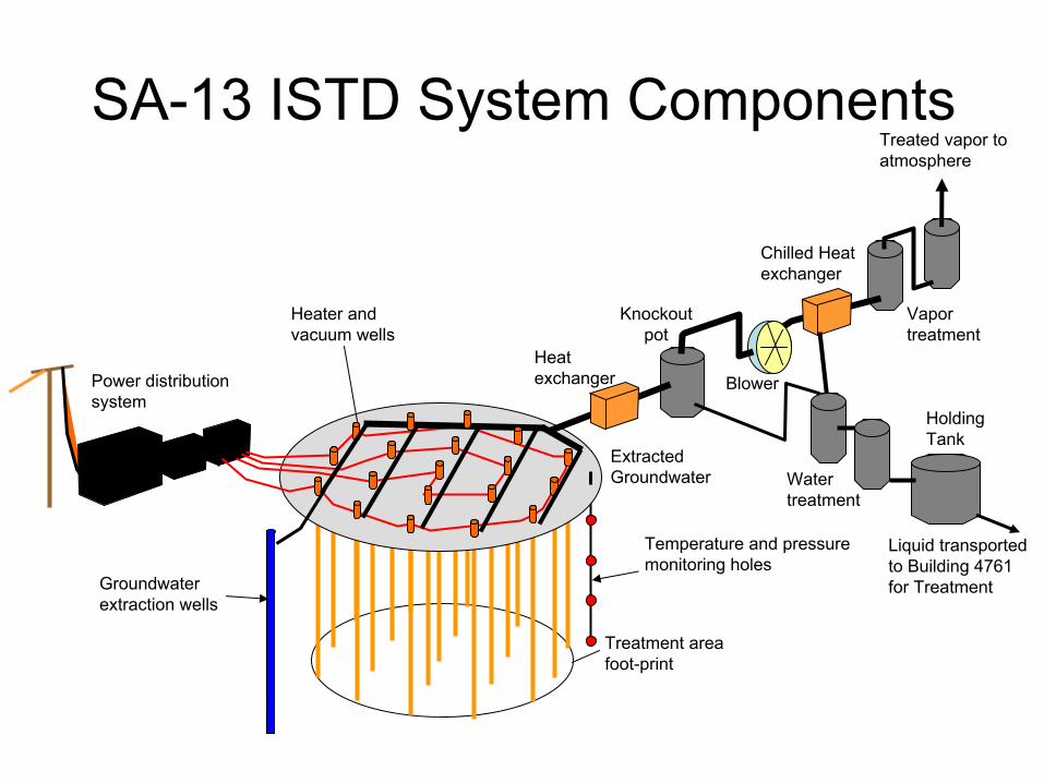
SA-13 ISTD System Components
Power distribution system
Vapor treatment
Knockout pot
Blower
Holding Tank
Heater and vacuum wells
Treated vapor to atmosphere
Heat exchanger
Treatment area foot-print
Temperature and pressure monitoring holes
Groundwater extraction wells
Liquid transported to Building 4761 for Treatment
Chilled Heat exchanger
Water treatment
Extracted Groundwater

.
Process Trailer→
Heater Wells
Heater-Vacuum Well
Heater-VacuumWell
Hexagonal Well Pattern
Heater-Only Well
Heater-VacuumWell
Very Hot Thermal DestructionZone
ISTD Overview

Heaters

SA-13 In-Situ Thermal TS•
Target treatment zone (TTZ) delineation:–
Treatment area of approximately 500 square feet.–
Vertical interval from 15’
to 42’
ft below land surface including 5 feet into underlying bedrock.
•
Agencies suggested ISTT implementation as a CERCLA interim action under an Interim Record of Decision (IROD).
•
Primary performance objective –
Reduce estimated mass and average concentrations of TCE in TTZ soil and groundwater by 80% or greater.
•
[Reference SITE MAPS/TTZ FIGURES]

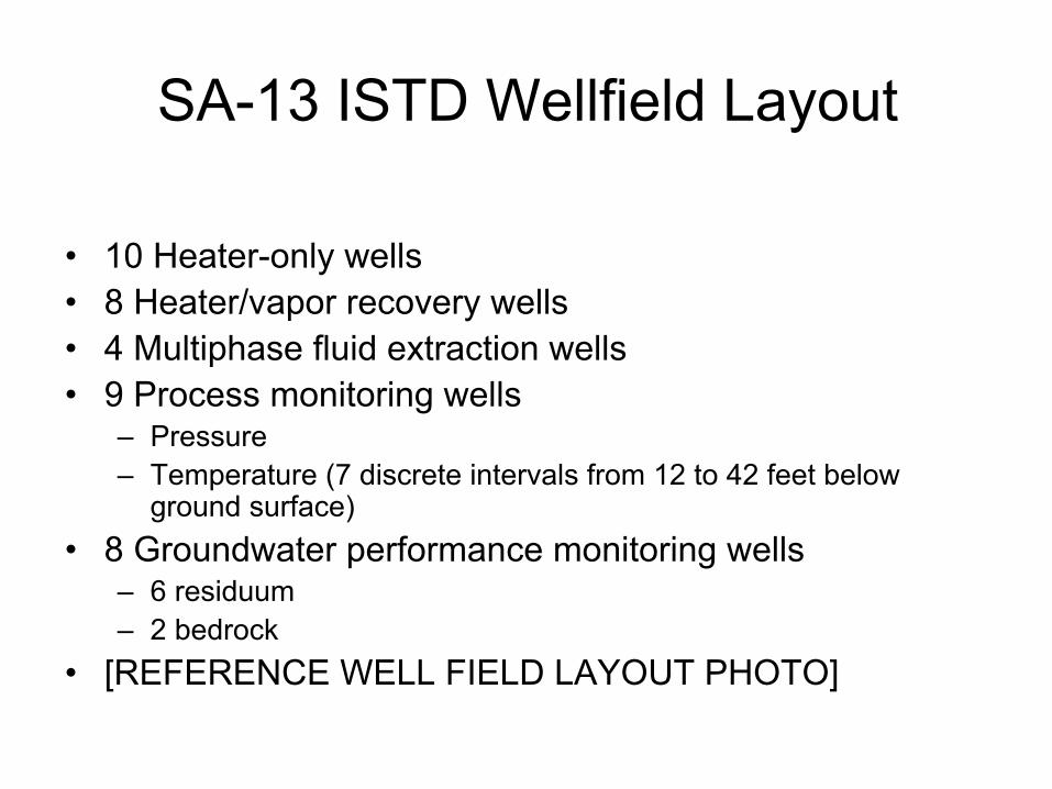
SA-13 ISTD Wellfield
Layout
•
10 Heater-only wells•
8 Heater/vapor recovery wells
•
4 Multiphase fluid extraction wells •
9 Process monitoring wells –
Pressure–
Temperature (7 discrete intervals from 12 to 42 feet below ground surface)
•
8 Groundwater performance monitoring wells –
6 residuum–
2 bedrock•
[REFERENCE WELL FIELD LAYOUT PHOTO]
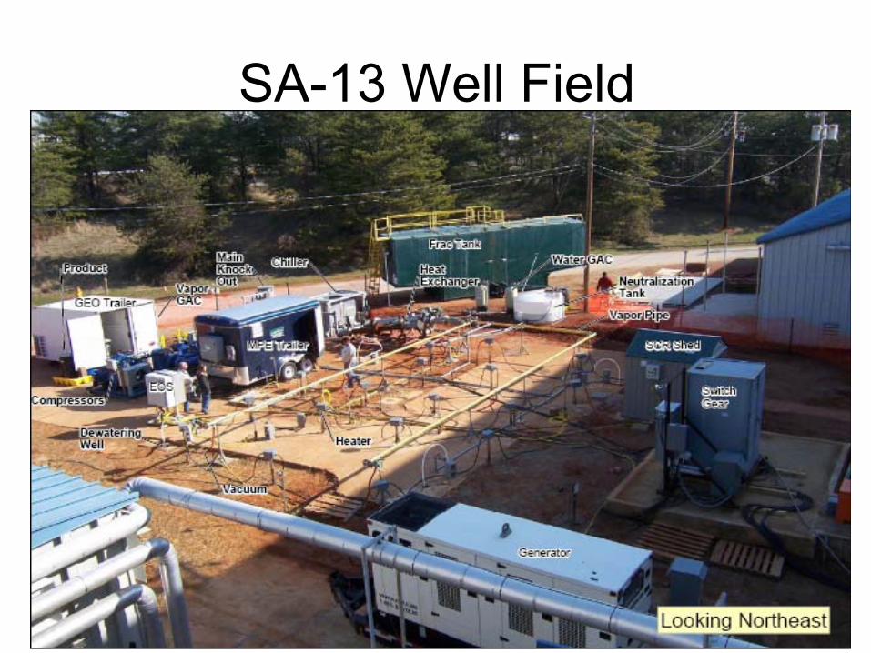
SA-13 Well Field

ISTD Process and Instrumentation
Vapor and entrained liquid from well- field
Liquid-vapor separator
Blower
Holding tank for
condensate
Vapors to stack
Water to discharge or holding tank
Vapor GAC polisher
Liquid GAC
Heat exchanger
Chilling compression
unit
NAPL waste tank
T
P
F
S
S
S
S
SS
ST T
T
F
F
P
P
F
P
S
Temperature
Pressure
Flow
Sampling point
Vapor and entrained liquid from well- field
Liquid-vapor separator
Blower
Holding tank for
condensate
Vapors to stack
Water to discharge or holding tank
Vapor GAC polisher
Liquid GAC
Heat exchanger
Chilling compression
unit
NAPL waste tank
TT
PP
FF
SS
SS
SS
SS
SSSS
SSTT TT
TT
FF
FF
PP
PP
FF
PP
SS
Temperature
Pressure
Flow
Sampling point

Treatment Zone TemperatureAverage Treatment Zone Temperature as a Function of Time
0
10
20
30
40
50
60
70
80
90
100
110
0 10 20 30 40 50 60 70 80 90 100Treatment Days
Tem
pera
ture
(C)
MW00-312 MW00-313 MW00-314 MW00-318
(73 C) TCE & Water Co-Boiling Point

SA-13 System Removals

SA-13 DNAPL (typical photos)

Treatment Results 1Soil Sample Results MW00-312 / SB05-244
-40
-35
-30
-25
-20
-15
-10
-5
0
0.00 0.01 0.10 1.00 10.00 100.00 1000.00TCE Concentration (mg/kg)
Dep
th B
elow
Gro
und
Surf
ace
(feet
)
Post Treatment Pretreatment
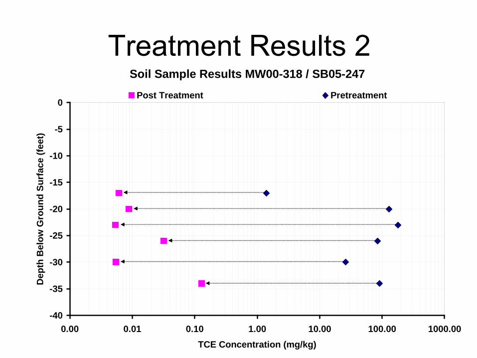
Treatment Results 2Soil Sample Results MW00-318 / SB05-247
-40
-35
-30
-25
-20
-15
-10
-5
0
0.00 0.01 0.10 1.00 10.00 100.00 1000.00TCE Concentration (mg/kg)
Dep
th B
elow
Gro
und
Surf
ace
(feet
)
Post Treatment Pretreatment

Treatment Results 3Soil Sample Results MW00-314 / SB05-246
-40
-35
-30
-25
-20
-15
-10
-5
0
0.00 0.01 0.10 1.00 10.00 100.00 1000.00TCE Concentration (mg/kg)
Dep
th B
elow
Gro
und
Surf
ace
(feet
)
Post Treatment Pretreatment

Treatment Results 4Soil Sample Results MW00-313 / SB05-245
-40
-35
-30
-25
-20
-15
-10
-5
0
0.00 0.01 0.10 1.00 10.00 100.00 1000.00TCE Concentration (mg/kg)
Dep
th B
elow
Gro
und
Surf
ace
(feet
)
Post Treatment Pretreatment

Treatment Results 5Treatment Zone Average Groundwater Concentration
1
10
100
1000
10000
100000
Dec-06 Feb-07 Apr-07 Jun-07
TCE
Con
cent
ratio
n (u
g/L) 80% Average Reduction Value = 16,700 ug/L
TCE MCL = 5 ug/L
ISTT System Operation

SA-13 TCE Removal Summary
Average Results Residuum Media
Soil GroundwaterPre-Treatment Concentrations 57.4 mg/kg 77,860 µg/l
Pre-Treatment Mass 39.1 lbs 26.3 lbs
Post-Treatment Concentrations 0.05 mg/kg 2,870 µg/l
Post-Treatment Mass 0.09 lbs 5.4 lbs
Concentration Reduction 99.9 % 96.3 %
Estimated Mass Reduction 99.8 % ~ 80%

Summary•
The Interim Action removed approximately 400 pounds of TCE.
•
First application of ISTT at MSFC and in the state of Alabama.
•
Interim remedial action objectives and goals established for ISTT at SA-13 were achieved.
•
Technology proved highly effective for:–
source area mass reduction;
–
chlorinated solvent removal from the saturated and unsaturated residuum; and
–
treatment of heterogeneous subsurface environments.