in-line inspection technology to detect, locate, and measure pipeline … · 2015-06-16 · in-line...
TRANSCRIPT

E n e r g y R e s e a r c h a n d D e v e l o p m e n t D i v i s i o n F I N A L P R O J E C T R E P O R T
IN-LINE INSPECTION TECHNOLOGY TO DETECT, LOCATE, AND MEASURE PIPELINE GIRTH WELD DEFECTS A Field Demonstration
FEBRUARY 2015 CE C-500-2015-028
Prepared for: California Energy Commission Prepared by: Diakont Advanced Technologies

PREPARED BY: Primary Author(s): Kyle Zaffino Diakont Advanced Technologies, Inc. 3853 Calle Fortunada San Diego, CA 92123 Phone: 858-551-5551 | Fax: 858-504-7065 http://www.diakont.com Contract Number: PIR-12-009 Prepared for: California Energy Commission Avtar Bining, Ph.D. Contract Manager Fernando Pina Office Manager Energy Systems Research Office Laurie ten Hope Deputy Director ENERGY RESEARCH AND DEVELOPMENT DIVISION Robert P. Oglesby Executive Director
DISCLAIMER This report was prepared as the result of work sponsored by the California Energy Commission. It does not necessarily represent the views of the Energy Commission, its employees or the State of California. The Energy Commission, the State of California, its employees, contractors and subcontractors make no warranty, express or implied, and assume no legal liability for the information in this report; nor does any party represent that the uses of this information will not infringe upon privately owned rights. This report has not been approved or disapproved by the California Energy Commission nor has the California Energy Commission passed upon the accuracy or adequacy of the information in this report.

ACKNOWLEDGEMENTS
Diakont Advanced Technologies, Inc. (Diakont) thanks the California Energy Commission for the opportunity through this study to develop and demonstrate in-line inspection technology that meets the serious need for accurate girth weld inspection.
The Diakont project team would like to thank François Rongere, Ben Wu, Lloyd Schaefer, Bennie Barnes, Frank Dauby, Jeff Janvier, and all the other engineers and managers at Pacific Gas & Electric; they provided access to mockup and operational pipeline sections that allowed for the verification of the technology, and their devoted interest in the technology validated the value of the project.
Diakont would also like to thank those associates who devoted their time and innovative energy to the successful completion of this project. These include (in alphabetical order): Brian Carlson, Sergei Dmitriev, Andrew Ellis, Jacco Geomans, Denis Gurin, Tobias Haswell, William Lehman, Derek Marich, Maxim Mazurenko, Victoria Nguyen, Edward Petit de Mange, Vitali Romanovich, Mikhail Sokolov, Alekander Tsyuk, and Kyle Zaffino.
i

PREFACE
The California Energy Commission Energy Research and Development Division supports public interest energy research and development that will help improve the quality of life in California by bringing environmentally safe, affordable, and reliable energy services and products to the marketplace.
The Energy Research and Development Division conducts public interest research, development, and demonstration (RD&D) projects to benefit California.
The Energy Research and Development Division strives to conduct the most promising public interest energy research by partnering with RD&D entities, including individuals, businesses, utilities, and public or private research institutions.
Energy Research and Development Division funding efforts are focused on the following RD&D program areas:
• Buildings End-Use Energy Efficiency
• Energy Innovations Small Grants
• Energy-Related Environmental Research
• Energy Systems Integration
• Environmentally Preferred Advanced Generation
• Industrial/Agricultural/Water End-Use Energy Efficiency
• Renewable Energy Technologies
• Transportation
In-Line Inspection Technology to Detect, Locate, and Measure Pipeline Girth Weld Defects is the final report for the Girth Weld Inspection project (grant number PIR-12-009) conducted by Diakont Advanced Technologies, Inc. The information from this project contributes to the Energy Research and Development Division’s Energy Systems Integration Program.
For more information about the Energy Research and Development Division, please visit the Energy Commission’s website at www.energy.ca.gov/research/ or contact the Energy Commission at 916-327-1551.
ii
ABSTRACT
Between January 2010 and November 2014, pipeline operators reported 1,082 incidents in gas transmission, gathering, and distribution pipelines in the United States. These incidents resulted in a total of 67 deaths, 341 injuries, and more than $246 million in property damage. Efficient in-line methods of assessing pipeline integrity, especially girth welds, are crucial to ensure public and environmental safety; pipelines typically are buried, making manual inspection through excavation expensive or unreasonable. Additionally, mechanical, operational, or economic constraints may limit operators from using standard flow-driven in-line inspection tools (also called pigs) in natural gas and petroleum liquid pipelines. Diakont Advanced Technologies, Inc. uses self-propelled, tethered Remotely Operated Diagnostic Inspection System robotic in-line inspection multi-tools to detect, locate, and measure defects in such pipelines. Girth welds and their adjacent heat-affected zones present unique inspection challenges, and welds with existing flaws subject to stress can lead to weld failure. Industry standard methods of detecting weld defects include magnetic flux leakage and hydrostatic testing; however, these technologies are limited in effectiveness and feasibility to pipeline operation. Diakont has developed a girth weld scanner inspection module for use with their existing robotic tool system to remotely inspect natural gas pipeline girth welds from inside the pipe. Keywords: Diakont, non-destructive, pipeline integrity, smart pig, girth weld, EMAT, NDE, NDT, UT, ILI, in-line inspection, unpiggable, integrity management
Please use the following citation for this report:
Zaffino, Kyle. (Diakont Advanced Technologies, Inc.). 2015. In-Line Inspection Technology to Detect, Locate, and Measure Pipeline Girth Weld Defects. California Energy Commission. Publication number: CEC-500-2015-028.
iii
TABLE OF CONTENTS
Acknowledgements ................................................................................................................................... i
PREFACE ................................................................................................................................................... ii
ABSTRACT .............................................................................................................................................. iii
TABLE OF CONTENTS ......................................................................................................................... iv
LIST OF FIGURES .................................................................................................................................. vi
LIST OF TABLES ................................................................................................................................... vii
EXECUTIVE SUMMARY ........................................................................................................................ 1
Introduction ........................................................................................................................................ 1
Project Purpose ................................................................................................................................... 1
Project Results ..................................................................................................................................... 1
Project Benefits ................................................................................................................................... 2
CHAPTER 1: Introduction ...................................................................................................................... 5
1.1 Problem Statement ..................................................................................................................... 5
1.2 Project Goals ............................................................................................................................... 7
1.3 Project Objectives ....................................................................................................................... 7
CHAPTER 2: Internal Development ..................................................................................................... 8
2.1 Transducer Development ......................................................................................................... 8
2.1.1 Traditional Weld Inspection Methods ............................................................................ 8
2.1.2 Detection of Metal Loss Defects Using Shear Waves .................................................... 9
2.1.3 Traditional Piezoelectric Inspection Tools .................................................................... 10
2.1.4 Electromagnetic Inspection Tools .................................................................................. 10
2.1.5 Use of Electromagnetic Inspection Tools for Weld Inspection .................................. 12
2.2 Sensor Package Design ............................................................................................................ 13
2.2.1 Hardware Research and Development ......................................................................... 13
2.2.2 Software Research and Development ........................................................................... 14
2.2.3 Validation and Verification Test Procedures ............................................................... 16
iv

2.3 High-Speed Data Connection Subsystem Development .................................................... 17
2.3.1 Hardware Research and Development ......................................................................... 17
2.3.2 Software Research and Development ........................................................................... 17
2.3.3 Validation and Verification Test Procedures ............................................................... 18
CHAPTER 3: Prototype Fabrication and Testing .............................................................................. 19
3.1 Prototype Fabrication .............................................................................................................. 19
3.2 Internal Prototype Testing ...................................................................................................... 20
3.2.1 Mechanical Information .................................................................................................. 20
3.2.2 Software Information ....................................................................................................... 21
3.2.3 Electrical Information ...................................................................................................... 22
3.2.4 Laboratory Test Stands .................................................................................................... 22
CHAPTER 4: Testing on Customer Test Loops ................................................................................. 26
4.1 First Artificial Sample .............................................................................................................. 26
4.2 Second Artificial Sample ......................................................................................................... 28
CHAPTER 5: Demonstration Inspections on Operational Pipelines ............................................ 29
5.1 El Camino Real Line L132 ....................................................................................................... 29
CHAPTER 6: Data Collection and Analysis ....................................................................................... 31
6.1 Software Overview .................................................................................................................. 31
6.2 Data Collection Criteria ........................................................................................................... 32
6.3 Explanation of Field Data ....................................................................................................... 36
CHAPTER 7: Commercialization ......................................................................................................... 37
7.1 Technology Transfer Activities .............................................................................................. 37
7.2 Production Readiness Plan ..................................................................................................... 38
CHAPTER 8: Conclusion ....................................................................................................................... 40
GLOSSARY .............................................................................................................................................. 41
REFERENCES .......................................................................................................................................... 44
APPENDIX A: Data .............................................................................................................................. A-1
APPENDIX B: Inspection Images ...................................................................................................... B-1
v

LIST OF FIGURES
Figure 1: RODIS Crawler .......................................................................................................................... 5
Figure 2: Shear Wave Initiation in a Test Object .................................................................................... 9
Figure 3: Shear Wave (0° Angle) Initiation and Reflection .................................................................. 9
Figure 4: Piezoelectric Ultrasonic Wave Initiation Example .............................................................. 10
Figure 5: Detailed EMAT UT Method Diagram .................................................................................. 11
Figure 6: RODIS During EMAT Inspection .......................................................................................... 11
Figure 7: Multi-Channel EMAT Scanning Steps .................................................................................. 13
Figure 8: Piezoelectric Weld Inspection ................................................................................................ 13
Figure 9: Diakont Multi-Channel FT EMAT Weld Inspection .......................................................... 14
Figure 10: Complete Set of Individual FT Scans .................................................................................. 14
Figure 11: Frequency-Time Matrix Scan ............................................................................................... 15
Figure 12: Sample GWS Readout Screen .............................................................................................. 15
Figure 13: GWS Transducer Validation ................................................................................................ 16
Figure 14: Comparison of FT Scans to X-ray Scan ............................................................................... 17
Figure 15: New Remote Control Unit .................................................................................................... 19
Figure 16: EMAT Transducer Comparison .......................................................................................... 20
Figure 17: GWS Module Installed on RODIS Crawler........................................................................ 20
Figure 18: RODIS Control Software ...................................................................................................... 21
Figure 19: Control Station Display ........................................................................................................ 22
Figure 20: Horizontal Test Stand with Elevation Change and 90° Bend .......................................... 23
Figure 21: Vertical Test Stand with Sag Bend ...................................................................................... 24
Figure 22: Portable Crane for Vertical Entry ........................................................................................ 25
Figure 23: Test Loop Inspection ............................................................................................................. 26
Figure 24: Test Pipe Close-Up ................................................................................................................ 27
Figure 25: Inspection Area of El Camino Real L132 at A Street ........................................................ 29
Figure 26: GWS Flat Defect Specifications ............................................................................................ 33
Figure 27: GWS Volumetric Defect Specifications............................................................................... 33
vi

Figure 28: Wall Thickness Inspection Limitation ................................................................................ 35
Figure 29: Defect Dimension Measurement Limitations .................................................................... 35
LIST OF TABLES
Table 1: Girth Weld Anomaly Test Pipe – First Sample ..................................................................... 26
Table 2: Girth Weld Anomaly Test Pipe – Second Sample ................................................................ 28
Table 3: Anomalies in a Girth Weld or an HAZ .................................................................................. 32
Table 4: Anomaly Location Accuracy ................................................................................................... 34
Table 5: Anomaly Detection Limitations .............................................................................................. 34
Table 6: Technology Transfer Plan ........................................................................................................ 38
Table 7: Five-Year Preliminary GWS Inspection Budget .................................................................... 39
vii
EXECUTIVE SUMMARY
Introduction Managing the integrity of natural gas pipelines is essential to avert catastrophic failures such as the 2010 San Bruno explosion, which can result in loss of life, environmental devastation, damage to property, and loss of revenue. Although federal and state regulations require pipeline operators to maintain programs to manage the integrity of their pipelines, existing technologies cannot adequately inspect for anomalies within girth welds and their associated heat-affected zones.
Current best practices for inspecting girth welds generally rely on hydrotesting, where the inspector fills the pipe with water until the water pressure reaches a predetermined limit. There are several disadvantages to this practice; injecting water into the pipeline inherently increases risks of internal corrosion, and because pipes inspected this way either pass the test or burst, successful tests still cannot detect and locate non-critical anomalies.
Commercially available in-line inspection services use magnetic flux leakage technology to inspect girth weld defects, which create a magnetic field and detect distortions where the field leaks (i.e., where an anomaly disturbs the expected magnetic field). This method is less exact than the targeted beams used by ultrasonic tools. Additionally, the actual probabilities of detection and measurement accuracy of these tools have been questioned. Regardless of effectiveness, this technology is only available for pipeline sections that can be inspected using flow-driven in-line inspection tools (or smart pigs); the size of the equipment and the lack of self-propulsion prevent these tools from navigating some common pipeline layouts.
Project Purpose Legacy pipelines do not always have reliable data on the integrity of their girth welds. Stress applied to girth welds with existing flaws can lead to weld failure. Several external factors can cause these forces, most commonly ground movement (e.g., sinkholes, mine subsidence, landshifts, seismic activity) reducing weight support of the pipeline. Diakont Advanced Technologies, Inc. (Diakont) has developed new girth weld scanning technology that provides non-destructive in-line inspection of welds and their associated heat-affected zones. This new technology replaces or supplements current best practices for inspecting girth welds.
Project Results This project fulfilled the challenge of comprehensive quantitative remote girth weld inspection from inside the pipeline, including two field demonstrations on three customer-selected inspection objects. Diakont’s technology significantly improves operational performance compared to currently available girth weld inspection technology, using robotics to extend inspection reach into unpiggable pipelines. The commercialized technology can potentially lower inspection costs for pipeline operators, reducing ratepayer costs and allowing the potential for increased inspection scope/frequency.
1

Smart pigs require special entry and exit points; Diakont’s crawler tools can be inserted through a gap in the pipe as small as two linear feet and using a hole dug in compliance with Occupational Safety and Health Administration standards as small as four feet square to gain access to underground pipelines. Using small holes, or adapting to pre-existing holes dug for other work purposes, saves excavation time and costs for the operator, allowing them to inspect more high-risk pipe segments in a shorter time frame under a limited inspection budget.
The operator also has greater flexibility in choosing an inspection route by entering through a small gap in the pipe, especially if the operator can offer access by simply removing a piece of the pipeline at a convenient location. The small footprint of Diakont’s tool system, as well as the simplicity of system set-up, use, and tear-down, provide flexibility in working with an operator’s maintenance schedule to maximize operator convenience and minimize service interruptions to consumers.
Smart pigs have limited ability to travel through common pipeline features such as bends, elevation changes, and valves due to their size and the difficulty in propelling them. Diakont’s small self-propelled crawler tools were specifically designed to inspect such pipeline features.
Since smart pigs are independent and flow-driven, operational changes during the inspection are impossible; any corrections to the process or attempts to re-examine an area require another full tool run. Diakont’s crawler tools are controlled and monitored by expert technicians for the duration of a tool run. The technicians can address any unexpected issues within the pipeline as well as manually re-examine items of interest immediately, saving time and guaranteeing precise inspection.Project Benefits The technology developed through this project is suitable for use in gas and petroleum pipelines for California and the rest of the world. Additionally, this technology is compatible with an operator’s ground movement risk management program; the operator can use their geographic information system and construction records to rank pipeline sections in order of risk, then schedule the high-risk sections for inspection to assess girth weld integrity.
This new technology can benefit California by:
• Increasing true pipeline integrity awareness
• Increasing inspection and repair effectiveness, accuracy, and efficiency
• Improving safety and service for California residents and the environment
The combination of factors that lead to pipeline girth weld degradation poses a unique inspection challenge; because welds experience the effects of tensile loading non-uniformly, each girth weld must be inspected in areas where an operator’s geographic information system indicates ground movement may place stress on a pipeline. A sample inspection is inadequate to validate such a pipeline’s structural integrity.
Excavation costs for direct examination may range from $500,000 to $1 million for a typical risk area length and location, which is ten times the cost of the actual inspection.
2
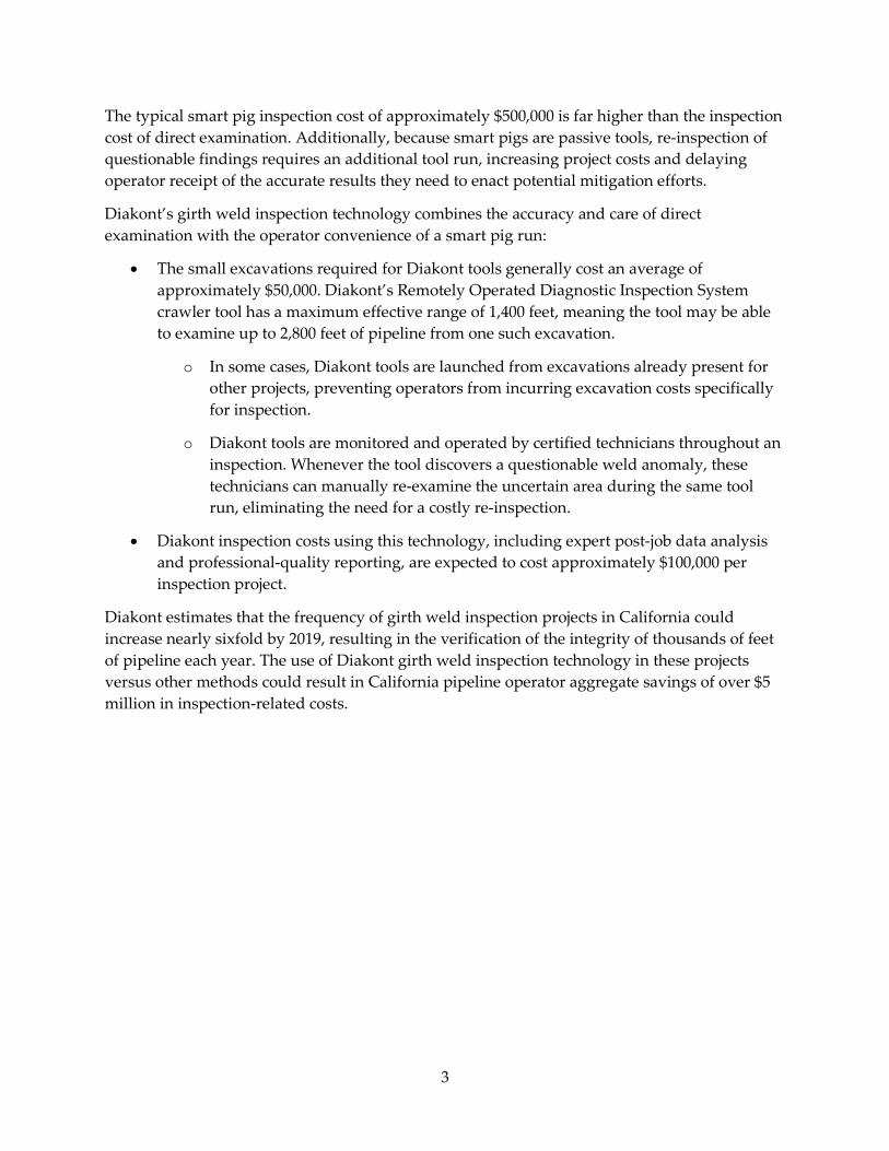
The typical smart pig inspection cost of approximately $500,000 is far higher than the inspection cost of direct examination. Additionally, because smart pigs are passive tools, re-inspection of questionable findings requires an additional tool run, increasing project costs and delaying operator receipt of the accurate results they need to enact potential mitigation efforts.
Diakont’s girth weld inspection technology combines the accuracy and care of direct examination with the operator convenience of a smart pig run:
• The small excavations required for Diakont tools generally cost an average of approximately $50,000. Diakont’s Remotely Operated Diagnostic Inspection System crawler tool has a maximum effective range of 1,400 feet, meaning the tool may be able to examine up to 2,800 feet of pipeline from one such excavation.
o In some cases, Diakont tools are launched from excavations already present for other projects, preventing operators from incurring excavation costs specifically for inspection.
o Diakont tools are monitored and operated by certified technicians throughout an inspection. Whenever the tool discovers a questionable weld anomaly, these technicians can manually re-examine the uncertain area during the same tool run, eliminating the need for a costly re-inspection.
• Diakont inspection costs using this technology, including expert post-job data analysis and professional-quality reporting, are expected to cost approximately $100,000 per inspection project.
Diakont estimates that the frequency of girth weld inspection projects in California could increase nearly sixfold by 2019, resulting in the verification of the integrity of thousands of feet of pipeline each year. The use of Diakont girth weld inspection technology in these projects versus other methods could result in California pipeline operator aggregate savings of over $5 million in inspection-related costs.
3

4

CHAPTER 1: Introduction 1.1 Problem Statement One cause of the 2010 tragedy at San Bruno was determined by federal investigators to be defective pipeline welds (Dearen 2011). Girth weld anomalies are typically the result of either substandard construction or deficient post-construction inspection – many pipelines were installed during a period of time when inspection technology was unavailable or inadequate. Girth weld anomalies, combined with external loading on the pipeline (e.g., land shifts, severe weather, seismic activity), can eventually lead to a critical structural failure of the weld.
The Remotely Operated Diagnostic Inspection System (RODIS) is a class of crawler-type robotic in-line inspection (ILI) tools developed by Diakont Advanced Technologies, Inc. (Diakont) for detecting, characterizing, and measuring pipeline anomalies, and for surveying pipeline features. Figure 1 shows a front view of a RODIS crawler; note the socket on the front of the crawler where technicians install modules to perform different functions during an inspection. (For images of the crawler with modules attached and inside pipes, see Section 3.2.)
Figure 1: RODIS Crawler
Photo Credit: Diakont Advanced Technologies, Inc.
5

Traditional in-line inspection methods employ flow-driven tools called smart pigs. Although they are suitable for many types of pipelines, Diakont RODIS tools are specially designed to inspect lines whose design or operation limits inspections using traditional flow-driven ILI tools (or smart pigs):
• Smart pigs require special entry and exit points (called launchers and receivers, respectively), which may be permanently or temporarily installed. Diakont’s RODIS tools, however, do not require any such special fixtures, providing much greater flexibility in launch and retrieval options.
• Smart pigs have limited ability to travel through common pipeline features such as bends, elevation changes, unbarred tees, reducers, and valves. Diakont’s RODIS tools were specifically designed with the flexibility to inspect these types of pipeline features.
• Smart pigs are independent and flow-driven, making operational changes during the inspection impossible. Diakont’s RODIS tools are self-propelled and remotely operated by expert technicians – during a tool run, the tool operators can immediately address any unexpected issues within the pipeline as well as manually re-examine items of interest as soon as they are discovered.
The RODIS is a multi-tool platform, meaning that several different classes of defects can be inspected using the same base tool platform, in many cases during the same tool run.
Diakont’s new multi-channel electromagnetic acoustic transducer (EMAT) technology provides complete remote in-line inspection of girth welds and their associated heat-affected zone (HAZ) regions. This technology scans for construction defects as well as for operational defects.
This project took the multi-channel EMAT technology from the prototype level all the way to a commercialized level (see Table 6 for a preliminary schedule for future tool use), and the tool has successfully been deployed multiple times on demonstration and commercial bases.
Major tasks facing the project team within the scope of the project included:
• Developing a transducer and sensor package detailed design
• Developing high-speed data connection subsystem
• Fabricating and internally testing prototype
• Testing on PG&E test loop
• Demonstration inspection on PG&E operational pipeline
• Data collection and analysis
• Technology transfer activities
• Production readiness plan
6
1.2 Project Goals The goal of the project was to complete development of a robotic RODIS module that performs in-line inspection of girth welds on piggable and unpiggable carbon steel pipelines. The project intended to take the technology from the prototype level all the way to a commercial level of performance.
This project completed development of a module for use with existing RODIS tools that inspects girth welds on 30 inch – 56 inch pipe sizes. The project is also a milestone toward Diakont’s development of a follow-on RODIS module for highly accurate automated in-line real-time long seam weld inspection. Anomalies detected by the module include:
• Incomplete fusion
• Burn-through
• Slag inclusions
• Cracks and crack-like defects
• Undercutting
• Excess reinforcement
• Porosity defects
• Lack of penetration
See Appendix B.2 for detailed descriptions of these anomalies.
1.3 Project Objectives This project achieved its primary objective of developing and demonstrating a non-destructive ILI solution for detecting, measuring, and characterizing operational and construction defects within pipeline system girth welds and HAZ regions. The new technology was successfully demonstrated in Diakont laboratory tests, customer-requested examinations of third-party test inspection objects, and an active operator pipeline in an urban setting.
7
CHAPTER 2: Internal Development This chapter describes general in-line inspection concepts and details the application of these concepts to the problem of accurately scanning pipeline welds for anomalies.
2.1 Transducer Development This section describes the difference between traditional inspection methods and EMAT inspection methods, as well as the particular application of EMAT technology used in the girth weld scanner (GWS) module.
2.1.1 Traditional Weld Inspection Methods Traditional girth weld inspection methods included hydrotesting, external ultrasonic thickness (UT) testing, and smart pigs employing magnetic flux leakage (MFL) technology.
Hydrotesting involves filling a section of a pipeline with water, pressurizing the pipe to a set test pressure, and holding the pipe at the test pressure for a pre-determined length of time. Though this test method reveals flaws in the test area, it is not ideal:
• The test can only show whether the pipe bursts under pressure.
o A successful test does not identify the presence of non-critical flaws.
o A failed test results in uncontrolled water loss via the failure, creating hazards and possibly contaminating the environment.
• A successful test does not provide the measurements of flaws. If they are revealed.
• Internal hoop stress is generally not a factor in girth weld flaw growth rate, meaning the particular pressure applied by hydrotesting may not detect critical flaws in girth welds.
External UT testing involves a technician manually examining the weld by applying a testing device to the outside of the pipe wall. This method allows an appropriate level of care in inspection, but it has drawbacks:
• This method requires the entire inspection area to be excavated, making it difficult and costly for in-service pipelines as well as exposing the inspection technician to the hazards inherent to working in a bell hole.
• This method is not feasible for lengthy inspection areas or for pipelines that cannot be excavated (e.g., crossings or pipelines that are encased; see Chapter 5).
• This method requires the removal of a portion of the pipeline coating, which increases the risk of future external corrosion.
8

MFL technology uses powerful magnets to create a magnetic field in the inspection object. A sensor located between the magnets monitors the magnetic field as the tool moves and records changes for analysis.
• MFL technology deployed via smart pig has variable reliability for the inspection of girth welds.
• Flow-driven smart pigs have access to limited portions of most pipelines.
2.1.2 Detection of Metal Loss Defects Using Shear Waves During a UT inspection using shear waves, a non-destructive examination (NDE) tool initiates shear waves on the material surface. These shear waves cause vibration in the inspection object, where the vibration direction is perpendicular to the direction of the wave. Figure 2 shows a diagram of this process, where the red vertical arrow represents the shear wave created by the tool and the black horizontal arrows represent the resultant vibrations in the inspection object.
Figure 2: Shear Wave Initiation in a Test Object
Photo Credit: Diakont Advanced Technologies, Inc.
The waves reflect from the opposite wall of the inspection object back to the point of origin. The residual thickness of the object is determined by measuring the time that elapses between initiating the original wave and receiving the reflection. Figure 3 shows a diagram of this process, where the red arrow at left represents the propagation of the ultrasonic wave initiated by the tool and the blue arrow at right represents the propagation of the wave reflected from the opposite pipe wall.
Figure 3: Shear Wave (0° Angle) Initiation and Reflection
Photo Credit: Diakont Advanced Technologies, Inc.
9
2.1.3 Traditional Piezoelectric Inspection Tools Traditional UT tools use piezoelectric transducers to initiate and receive ultrasonic waves. These transducers require liquid couplant between the transducer and the surface of the inspection object in order to transmit the ultrasonic waves. The inspected object’s surface also must be free of deposits/debris and coating.
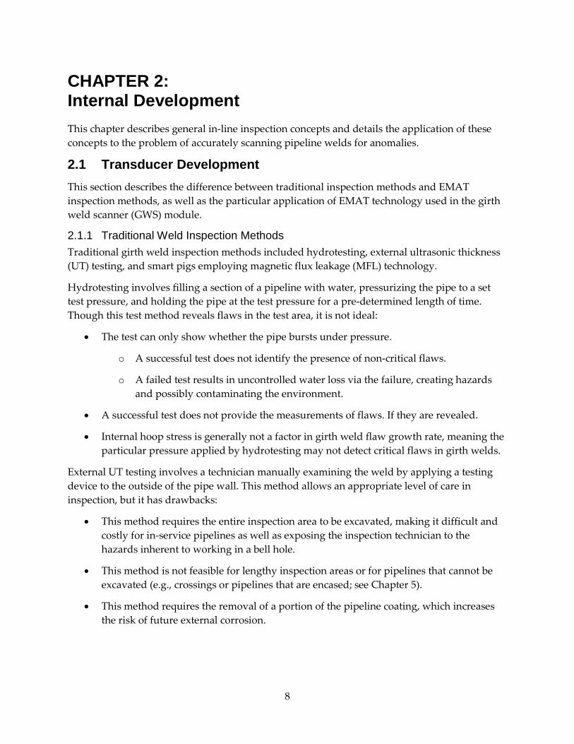
In the piezoelectric method, electrical voltage deforms a transducer. The resulting transverse vibrations are mechanically applied to the inspection object and generate the ultrasonic wave inside of it, perpendicular to the pipe surface. Figure 4 shows a diagram of this process, where the blue box represents a normal-incidence ultrasonic wave transducer, the green horizontal arrow represents the transverse vibrations, and the red wavy line represents an ultrasonic wave (in this case, a shear wave) created by the tool.
Figure 4: Piezoelectric Ultrasonic Wave Initiation Example
Photo Credit: Diakont Advanced Technologies, Inc.
In the pulse-echo method, the transducer also receives reflected waves, while the pitch-catch method uses one transducer to generate the original waves and a second transducer to receive reflected waves. Reflected waves pass through the liquid couplant and vibrate the recipient transducer. The transducer converts these vibrations to electric voltage, which is processed by the data acquisition system. Piezoelectric UT wave detection generally uses frequencies between 1 and 10 MHz.
2.1.4 Electromagnetic Inspection Tools Sometimes it is impossible and/or inappropriate to remove deposits or insert couplant (e.g., in remote sections of natural gas pipelines, environments where the temperature would freeze/evaporate the couplant, or environments that must remain dry). In these cases, a non-contact UT inspection method is necessary. EMAT technology is an ideal NDE method when high-resolution UT testing is required and mechanical coupling is impossible or impractical.
10
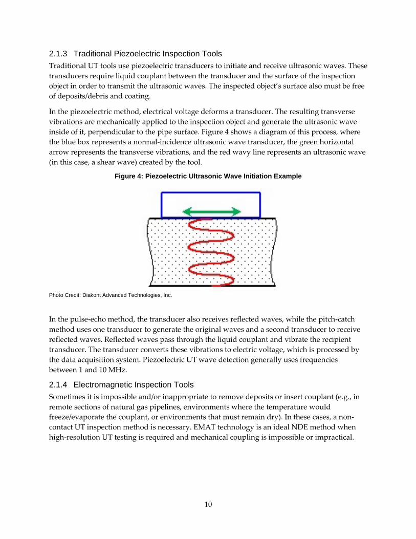
The EMAT transducer contains a coil and a magnet. When alternating current flows through the coil, an eddy current is generated in the inspected material. The interaction of this eddy current with the transducer magnetic field creates a Lorentz force in the surface layer of the metal. This Lorentz force is transmitted to the atomic matrix of the inspection object through electron collisions to generate ultrasonic shear waves with the same frequency as the current in the coil. Figure 5 shows a detailed diagram of the EMAT inspection method.
Figure 5: Detailed EMAT UT Method Diagram
Photo Credit: Innerspec Technologies
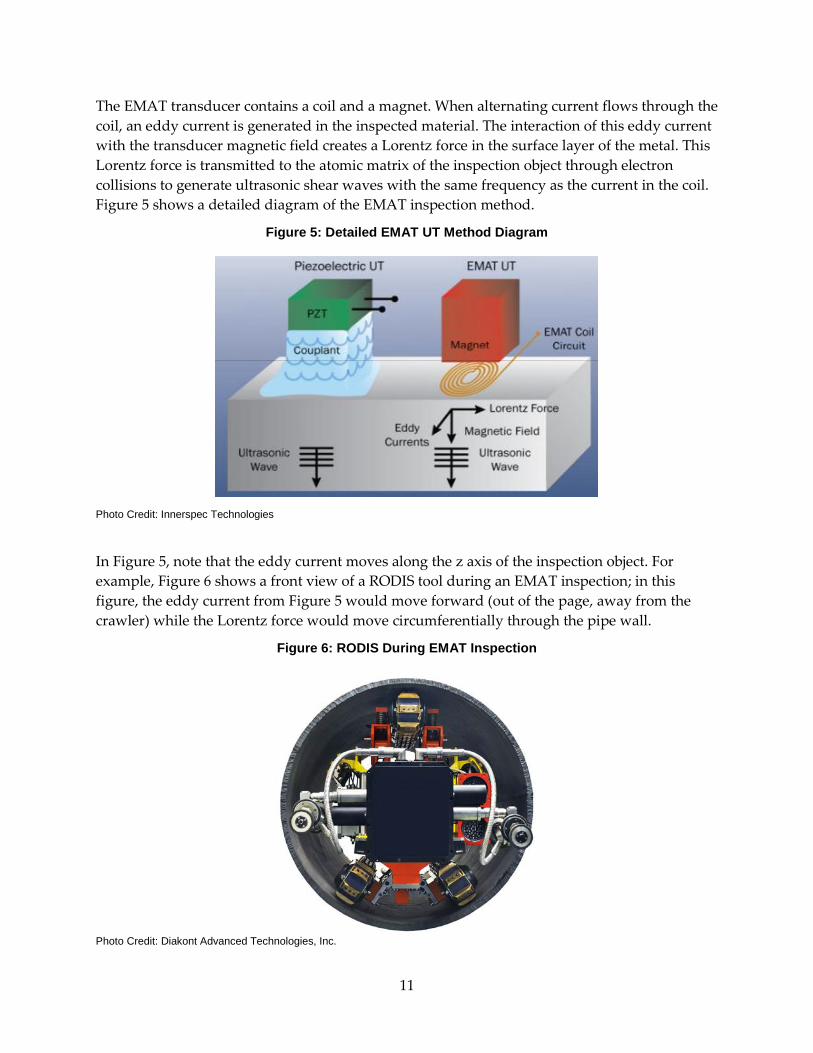
In Figure 5, note that the eddy current moves along the z axis of the inspection object. For example, Figure 6 shows a front view of a RODIS tool during an EMAT inspection; in this figure, the eddy current from Figure 5 would move forward (out of the page, away from the crawler) while the Lorentz force would move circumferentially through the pipe wall.
Figure 6: RODIS During EMAT Inspection
Photo Credit: Diakont Advanced Technologies, Inc.
11

The reflected waves are converted to electric current by the transducer. Like piezoelectric UT, EMAT UT inspections generally use frequencies between 1 and 10 MHz. Diakont EMAT UT internal inspection tools meet or exceed industry-standard specifications for length, width, and depth detection and sizing for ILI UT tools.
Transmission of ultrasonic shear waves in the inspection object using EMAT requires electromechanical coupling (i.e., electrical generation of a magnetic field in the space between the transducer and the inspection object). Because the waves do not need a physical medium to travel through en route to the transducer, no liquid couplant is required. In fact, EMAT transducers are designed to operate at a specific distance from the pipe wall, which allows the tool to tolerate some debris and/or surface irregularity.
2.1.5 Use of Electromagnetic Inspection Tools for Weld Inspection The solution is intended to be used in conjunction with other ILI programs within the same tool deployment, including:
• Pipeline feature surveys
• Wall thickness surveys
• External Corrosion Direct Assessment (ECDA)
• Internal Corrosion Direct Assessment (ICDA)
• Crack detection surveys
Girth welds are challenging to inspect due to their coarse, anisotropic grain structure, where anisotropic refers to the tendency of an object to exhibit properties with different values when measured in different directions (e.g., wood, whose grains may be parallel, irregular, or/and whorled). This structure attenuates the signal and creates wave velocity variances. A large data set, comprising multiple angles and frequencies, is required in order to capture all the resulting reflections during an inspection.
Diakont solved this issue with a multi-channel frequency-time (FT) EMAT scanning technique. A set of nine FT scans is generated on each side of the girth weld, with each frequency corresponding to a different input wave angle; operating frequencies range from 0.8 to 1.2 MHz to correspond to input angles between 35° and 45°.
12

Figure 7 shows a diagram of the GWS module’s inspection area, where the green portion of the pipe wall represents the propagation of shear waves in the inspection object.
Figure 7: Multi-Channel EMAT Scanning Steps
Photo Credit: Diakont Advanced Technologies, Inc.
2.2 Sensor Package Design 2.2.1 Hardware Research and Development Figure 8 shows a traditional piezoelectric weld inspection using angle beams. At left, the inspector moves the transducer in a meander pattern through the inspection area, along the path shown at right, inspecting the girth weld and the HAZ in three dimensions, using the principles described in Section 2.1.3.
Figure 8: Piezoelectric Weld Inspection
Photo Credit: Diakont Advanced Technologies, Inc.
13
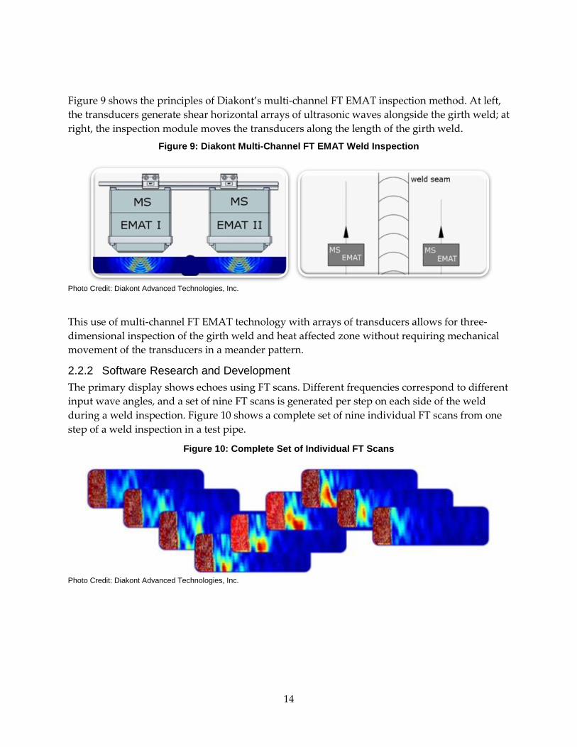
Figure 9 shows the principles of Diakont’s multi-channel FT EMAT inspection method. At left, the transducers generate shear horizontal arrays of ultrasonic waves alongside the girth weld; at right, the inspection module moves the transducers along the length of the girth weld.
Figure 9: Diakont Multi-Channel FT EMAT Weld Inspection
Photo Credit: Diakont Advanced Technologies, Inc.
This use of multi-channel FT EMAT technology with arrays of transducers allows for three-dimensional inspection of the girth weld and heat affected zone without requiring mechanical movement of the transducers in a meander pattern.
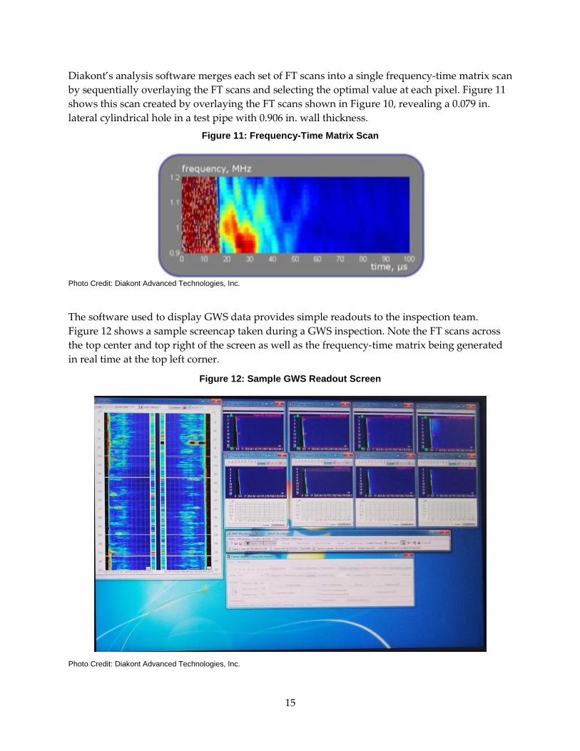
2.2.2 Software Research and Development The primary display shows echoes using FT scans. Different frequencies correspond to different input wave angles, and a set of nine FT scans is generated per step on each side of the weld during a weld inspection. Figure 10 shows a complete set of nine individual FT scans from one step of a weld inspection in a test pipe.
Figure 10: Complete Set of Individual FT Scans
Photo Credit: Diakont Advanced Technologies, Inc.
14
Diakont’s analysis software merges each set of FT scans into a single frequency-time matrix scan by sequentially overlaying the FT scans and selecting the optimal value at each pixel. Figure 11 shows this scan created by overlaying the FT scans shown in Figure 10, revealing a 0.079 in. lateral cylindrical hole in a test pipe with 0.906 in. wall thickness.
Figure 11: Frequency-Time Matrix Scan
Photo Credit: Diakont Advanced Technologies, Inc.
The software used to display GWS data provides simple readouts to the inspection team. Figure 12 shows a sample screencap taken during a GWS inspection. Note the FT scans across the top center and top right of the screen as well as the frequency-time matrix being generated in real time at the top left corner.
Figure 12: Sample GWS Readout Screen
Photo Credit: Diakont Advanced Technologies, Inc.
15
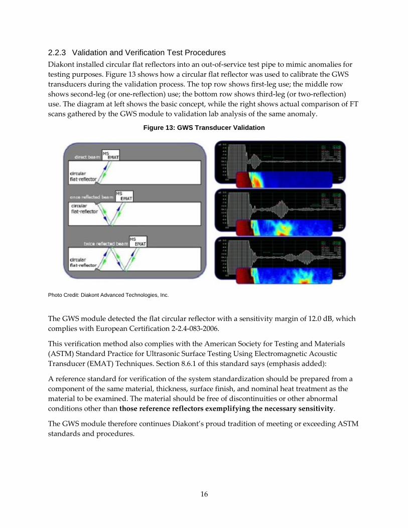
2.2.3 Validation and Verification Test Procedures Diakont installed circular flat reflectors into an out-of-service test pipe to mimic anomalies for testing purposes. Figure 13 shows how a circular flat reflector was used to calibrate the GWS transducers during the validation process. The top row shows first-leg use; the middle row shows second-leg (or one-reflection) use; the bottom row shows third-leg (or two-reflection) use. The diagram at left shows the basic concept, while the right shows actual comparison of FT scans gathered by the GWS module to validation lab analysis of the same anomaly.
Figure 13: GWS Transducer Validation
Photo Credit: Diakont Advanced Technologies, Inc.
The GWS module detected the flat circular reflector with a sensitivity margin of 12.0 dB, which complies with European Certification 2-2.4-083-2006.
This verification method also complies with the American Society for Testing and Materials (ASTM) Standard Practice for Ultrasonic Surface Testing Using Electromagnetic Acoustic Transducer (EMAT) Techniques. Section 8.6.1 of this standard says (emphasis added):
A reference standard for verification of the system standardization should be prepared from a component of the same material, thickness, surface finish, and nominal heat treatment as the material to be examined. The material should be free of discontinuities or other abnormal conditions other than those reference reflectors exemplifying the necessary sensitivity.
The GWS module therefore continues Diakont’s proud tradition of meeting or exceeding ASTM standards and procedures.
16

Figure 14 compares FT scans of a girth weld and its associated HAZ to an X-ray scan of the same area.
Figure 14: Comparison of FT Scans to X-ray Scan
Photo Credit: Diakont Advanced Technologies, Inc.
Both scans revealed a crack with the following dimensions:
• Crack depth – 0.04 in.
• Crack length – 0.60 in.
• Depth from internal pipe surface – 0.06 in.
2.3 High-Speed Data Connection Subsystem Development 2.3.1 Hardware Research and Development As a portion of this project, it was necessary to develop a communication system capable of transmitting a large amount of signal data from the transducers to the analysis and recording equipment outside the pipe. Diakont chose to use the very-high-bit-rate digital subscriber line (VDSL) format because it can send up to 100 MB/s over a single twisted-pair connection.
2.3.2 Software Research and Development In addition integrating VDSL communication hardware into the RODIS system, Diakont also designed custom software and firmware to manage the flow of data between the robot and the control system, appropriately prioritizing packets and regulating transfer speed. This included
17

the firmware running on the robot-end and controller-end VDSL modems, the FPGA controller on the robot, and the RODIS Controller and Inspector programs on the control system.
2.3.3 Validation and Verification Test Procedures Diakont confirmed the performance of the new high-speed data connection subsystem through mathematical validation and empirical verification tests, including a matrix set of systematic scenarios with various cable lengths, transducer settings, and degraded cable impedance (mathematical only). Once Diakont engineers completed their calculations, the team bench-tested the data connection subsystem. The communication system passed the bench top tests and the engineering team incorporated it into the tool.
18

CHAPTER 3: Prototype Fabrication and Testing 3.1 Prototype Fabrication Diakont specially developed crawler on-board electronics, a crawler control panel, an umbilical connection line, and remote control equipment in-house during this project to integrate the GWS module with the existing RODIS family of ILI tools.
Figure 15 shows the new remote control unit specially designed to work with the new technology. The new unit includes upgrades to existing features as well as new features such as an LCD display and a module rotation speed control dial.
Figure 15: New Remote Control Unit
Photo Credit: Diakont Advanced Technologies, Inc.
19
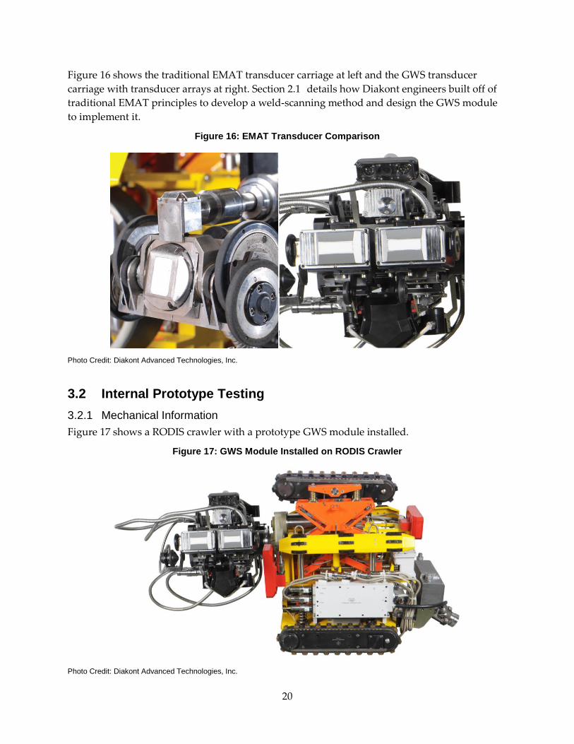
Figure 16 shows the traditional EMAT transducer carriage at left and the GWS transducer carriage with transducer arrays at right. Section 2.1 details how Diakont engineers built off of traditional EMAT principles to develop a weld-scanning method and design the GWS module to implement it.
Figure 16: EMAT Transducer Comparison
Photo Credit: Diakont Advanced Technologies, Inc.
3.2 Internal Prototype Testing 3.2.1 Mechanical Information Figure 17 shows a RODIS crawler with a prototype GWS module installed.
Figure 17: GWS Module Installed on RODIS Crawler
Photo Credit: Diakont Advanced Technologies, Inc.
20

The EMAT module has a lower profile and is lighter than the prototype GWS module. One goal of this project was therefore to make the GWS module as slim as possible and realize similar operational parameters to allow Diakont to offer girth weld inspection services alongside other pipeline inspection services without mechanical restriction.
3.2.2 Software Information Figure 18 shows the interface software that the inspection team uses to control the RODIS crawler during a GWS inspection. Note the two camera display windows – the inspection team can switch between the five cameras in each window to maintain an optimal view of the pipeline interior. In this example, both windows provide views from cameras permanently mounted on the crawler – the left window provides a view from the vertical camera on the rear right corner, while the right window provides a view from the rear horizontal camera.
Figure 18: RODIS Control Software
Photo Credit: Diakont Advanced Technologies, Inc.
21

Figure 19 shows the control station display used during a GWS inspection. The monitor at left shows the RODIS controls as displayed in Figure 18, while the monitor at right shows FT scans gathered by the tool as described in Section 2.2.2.
Figure 19: Control Station Display
Photo Credit: Diakont Advanced Technologies, Inc.
3.2.3 Electrical Information The GWS module has been integrated into the existing RODIS tool system without any extra electrical requirements. The system only requires access to 120V power.
3.2.4 Laboratory Test Stands The RODIS crawlers have been extensively tested in laboratory settings and successfully inspected hundreds of thousands of feet of pipelines using other inspection modules. Diakont technicians validated the new GWS module on test stands in a controlled environment before deploying the module on real-world pipelines. These test stands were both artificial and post-operational pipelines, allowing engineers the opportunity to reproduce realistic field conditions in a controlled environment and fully optimize best practices for pipeline inspections.
22

Figure 20 shows a 36 inch outside diameter (OD) horizontal test stand located at a Diakont facility. This test stand includes both an elevation change and a 1.5D 90° bend (where 1.5D indicates that the turn radius is equal to 1.5 times the diameter). Technicians tested the RODIS from both ends, as shown below and in the high end of the test stand (at right in the figure), in order to optimize GWS module operation on an incline and in a lateral bend. The variation in entry heights also resulted in valuable practice inserting and removing the tool under a variety of conditions, making the technicians better able to adapt to unique field conditions.
Figure 20: Horizontal Test Stand with Elevation Change and 90° Bend
Photo Credit: Diakont Advanced Technologies, Inc.
23

Figure 21 shows a 36 inch OD vertical test stand with a 90° sag bend. Technicians tested the RODIS from both ends in order to optimize RODIS system operation in vertical pipelines and in sag bends as well as to practice critical safety procedures in a controlled environment.
Figure 21: Vertical Test Stand with Sag Bend
Photo Credit: Diakont Advanced Technologies, Inc.
Diakont typically uses a steel emergency retrieval cable when a RODIS tool is used in a pipeline with a significant downward angle, and technicians use an internally-designed crane to help load the crawler into vertical points of entry. Tests in the vertical test stand confirmed that this equipment is also appropriate when using the GWS module and helped optimize vertical loading techniques. This crane is visible in Figure 21 at the top of the test stand in the upper-right corner of the figure.
24
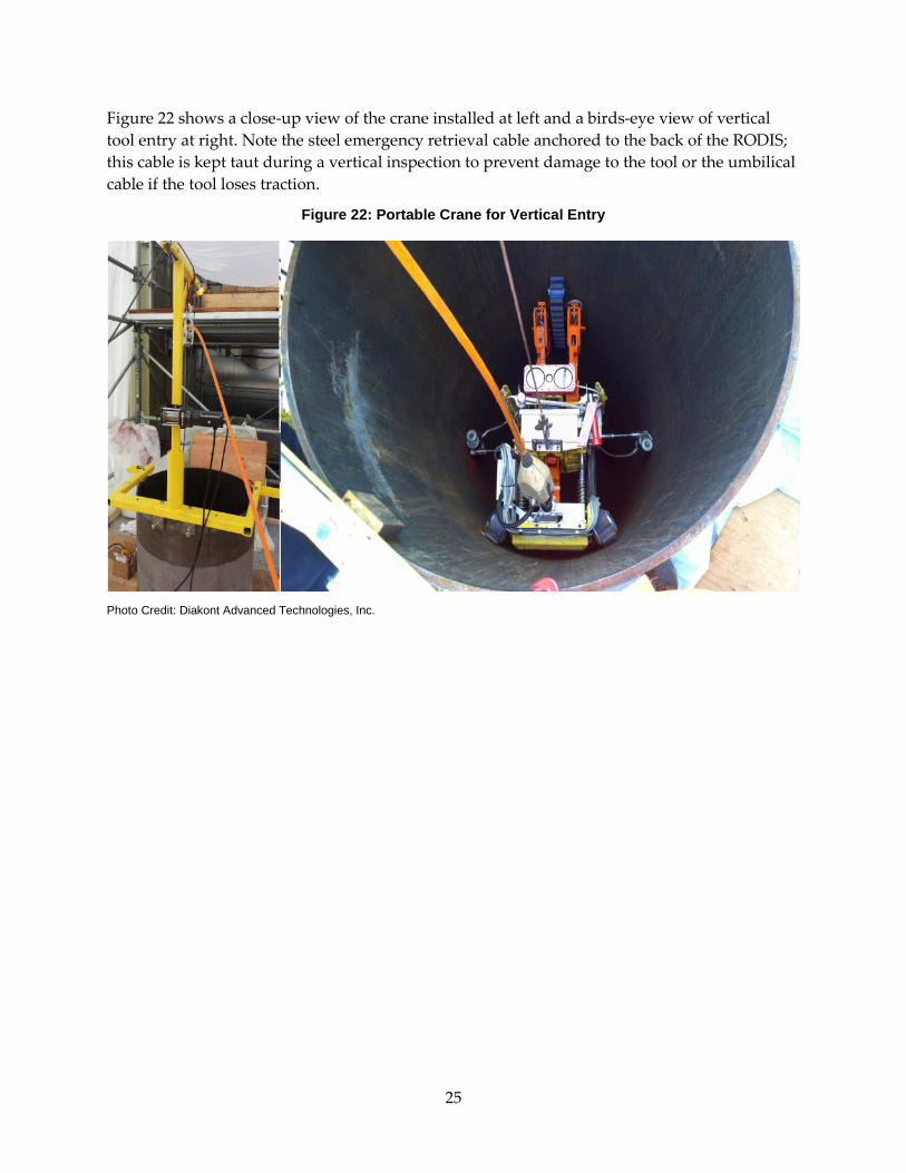
Figure 22 shows a close-up view of the crane installed at left and a birds-eye view of vertical tool entry at right. Note the steel emergency retrieval cable anchored to the back of the RODIS; this cable is kept taut during a vertical inspection to prevent damage to the tool or the umbilical cable if the tool loses traction.
Figure 22: Portable Crane for Vertical Entry
Photo Credit: Diakont Advanced Technologies, Inc.
25

CHAPTER 4: Testing on Customer Test Loops 4.1 First Artificial Sample Diakont inspected an artificially-fabricated girth weld anomaly test pipe provided by Pacific Gas & Electric (PG&E) using the GWS system on September 10 – September 12, 2014 in San Ramon, California. This girth weld was scanned three times. Table 1contains vital statistics for the test pipe.
Table 1: Girth Weld Anomaly Test Pipe – First Sample
Dimension Measurement
Length: 4.0 feet
Outside diameter: 36 inches
Wall thickness: 0.375 – 0.500 inch
Source: Diakont Advanced Technologies, Inc.
Figure 23 shows the inspection in progress. Note that the trailer functions as a control center as well as equipment storage and deployment; this figure shows the entirety of the work site fitting easily into six standard parking spaces, illustrating the versatility of the RODIS system.
Figure 23: Test Loop Inspection
Photo Credit: Diakont Advanced Technologies, Inc.
26

Figure 24 shows a close-up of the test pipe. Note the hash marks along the weld marking some of the pre-installed anomalies (e.g., EM16).
Figure 24: Test Pipe Close-Up
Photo Credit: Diakont Advanced Technologies, Inc.
This inspection revealed that the technology was acceptable, but inspection and data analysis methods required refinement.
• Reversing the normal rotation direction increased the probability of both defect location (i.e., diagnosis of defect as internal, external, or midwall) and angular coordinate reporting.
• The excluded signals threshold (i.e., cut-off for defect detection) was lowered in both circumferential length and nominal amplitude.
o Though this step led to discovery of a total of nine more potential anomalies, only five matched anomalies known to have been pre-installed in the sample, suggesting that avenue of data analysis requires further refinement.
• Further consideration of areas with signals from a weld bead led to discovery of eight additional defects, of which seven were known to have been pre-installed in the sample.
o Data on some defects was originally disregarded due to the presence of strong reflections from the weld bead – as described in Section 2.3.3 and displayed in Figure 12, reflections generally signal anomalies, not the weld bead itself.
• Due to the transducers generating waves in multiple directions (as shown in Figure 9 and explained in Section 2.2.1), some defects that present as false calls during a girth
27
weld inspection may actually be anomalies in the pipe wall that the GWS module is not equipped to analyze.
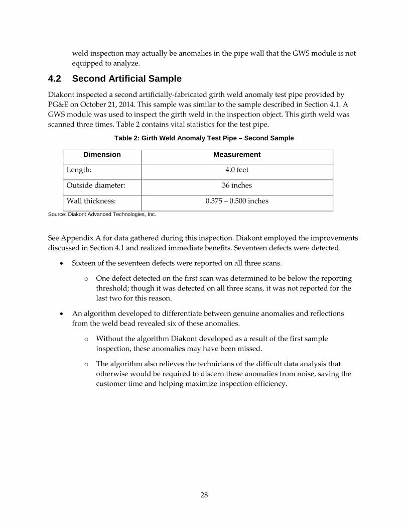
4.2 Second Artificial Sample Diakont inspected a second artificially-fabricated girth weld anomaly test pipe provided by PG&E on October 21, 2014. This sample was similar to the sample described in Section 4.1. A GWS module was used to inspect the girth weld in the inspection object. This girth weld was scanned three times. Table 2 contains vital statistics for the test pipe.
Table 2: Girth Weld Anomaly Test Pipe – Second Sample
Dimension Measurement
Length: 4.0 feet
Outside diameter: 36 inches
Wall thickness: 0.375 – 0.500 inches
Source: Diakont Advanced Technologies, Inc.
See Appendix A for data gathered during this inspection. Diakont employed the improvements discussed in Section 4.1 and realized immediate benefits. Seventeen defects were detected.
• Sixteen of the seventeen defects were reported on all three scans.
o One defect detected on the first scan was determined to be below the reporting threshold; though it was detected on all three scans, it was not reported for the last two for this reason.
• An algorithm developed to differentiate between genuine anomalies and reflections from the weld bead revealed six of these anomalies.
o Without the algorithm Diakont developed as a result of the first sample inspection, these anomalies may have been missed.
o The algorithm also relieves the technicians of the difficult data analysis that otherwise would be required to discern these anomalies from noise, saving the customer time and helping maximize inspection efficiency.
28

CHAPTER 5: Demonstration Inspections on Operational Pipelines This chapter describes Diakont inspections in sections of an active pipeline network. The inspection proved the viability of the RODIS system as a robust ILI technology delivery tool and confirmed that the GWS module was suitable for commercial use.
5.1 El Camino Real Line L132 Diakont inspected a section of PG&E natural gas line L132 approximately 285 feet in length at El Camino Real in South San Francisco on October 21 – October 22, 2014. Figure 25 shows the inspection area, which began approximately on A Street.
Figure 25: Inspection Area of El Camino Real L132 at A Street
Photo Credit: Pacific Gas & Electric, Google Earth
Diakont and PG&E were each pleased with the results of this inspection, which provided valuable insight into inspection method optimization.
Diakont inspected sixteen welds during this tool run. Given that this was explicitly intended to be a demonstration, Diakont and PG&E agreed that sixteen welds was a large enough sample size to accurately reflect inspection capabilities without unduly hampering other operator needs, learning key information that was not evident from the demonstrations on the single-weld sample objects described in Chapter 4.
Point of entry
End of inspection area
29
This tool run reinforced the utility of the tool in close quarters and demonstrated successful integration of the GWS module into the existing RODIS inspection system:
• The ability to bring the entire system to a pinpoint inspection area minimized the service area impacted by the inspection, reducing costly downtime for the customer as well as consumer inconvenience.
• The RODIS crawler’s small size reduces excavation time and cost:
o Diakont easily adapted to an existing bell hole that PG&E had created for another project – the inspection team’s only unique requirement was a point of entry into the pipeline, saving PG&E the expense and difficulty of excavating specifically for ILI purposes.
o The bell hole offered plenty of room for Diakont technicians to work; inspections have succeeded using bell holes as small as 8 feet square.
• The ability to inspect a small section of pipeline allowed the customer to optimize their pipeline integrity management schedule, prioritizing precise target areas for inspection and neatly slotting short inspections into a tight schedule rather than performing a long pig run to reach a small area.
30

CHAPTER 6: Data Collection and Analysis 6.1 Software Overview Diakont inspection software provides real-time data as the GWS module scans each girth weld. In addition to the visual output shown in Section 2.2.2, the software allows technicians to record the following information for each FT scan and each frequency-time matrix:
• Number – The number of the weld being inspected.
• Absolute coordinate – The length from the beginning of the route to the beginning of the element.
• Measurement WT – A wall thickness measurement of the element taken at a normal location on the pipe.
o A range should be noted if there is a large variation in normal pipe wall thickness – see Table 1 and Table 2.
• Notes – Anomaly identifiers and other observations go in this field (e.g., if the pipe was not cleaned properly, a technician might write “Debris impeded instrument readings at [degree position]”).
Whenever a suspected defect is located, technicians may stop the module at that location and record the following data:
• Number – Identifier of defect (e.g., A1, A2).
• Feature – Type of defect detected.
• Girth weld coordinate from launching point – Absolute coordinate of the girth weld.
• Initial clock position – The angular position of the beginning of the defect in degrees, as described by Figure 31.
• Final clock position – Angular position of the end of the defect in degrees, as described by Figure 31.
• Diameter/width and length – The diameter (or width, in the case of a flat defect) and axial length of the defect.
• Depth from ID – The distance from the ID to the location of the defect within the wall.
• Residual thickness – Remaining wall thickness, in the case of wall loss (e.g., corrosion).
• Reference thickness – The wall thickness of a normal section of pipe in close proximity to the defect being described (e.g., in the case of wall loss).
• Internal, External or Mid-Wall – Location of the defect in the wall of the pipe.
31

For a GWS inspection, Diakont reports include detailed tables of definitive defect readings as well as areas of signal loss (where structural integrity could not be adequately assessed) for each girth weld as shown in Appendix A.2.
6.2 Data Collection Criteria This section describes specific Diakont GWS inspection parameters.
Automatic EMAT scanning is the default method of pipeline inspection; however, automatic scans are not used within 4 in. of a girth weld or in HAZs. The traditional EMAT module cannot receive clear enough signals in these areas to determine the integrity of the inspection object.
The GWS module was specially designed to examine welds and HAZs. The module’s ability to detect flat anomalies was tested on grooves placed along a weld perpendicular to the test pipe’s surface, while the ability to detect volumetric anomalies was tested on a cylindrical side-drilled hole whose axis lay along a weld. Table 3 shows specifications for GWS inspection.
Table 3: Anomalies in a Girth Weld or an HAZ
Anomaly Defect Parameter Minimum Value
Flat defects (e.g., cracks, lack of fusion)
Depth ≥ 0.06 in.
Length ≥ 0.79 in.
Volumetric defects (e.g., blisters, non-metallic inclusions)
Diameter ≥ 0.12 in.
Length ≥ 0.79 in. Source: Diakont Advanced Technologies, Inc.
When using EMAT technology to inspect a girth weld, note the following:
• For the depth of a flat defect, the value in Table 3 is only valid where 0.39 ≤ t < 0.59 in. Where 0.59 ≤ t ≤ 1.18 in., the depth is 10% of t.
• For the diameter of a volumetric defect, the value in Table 3 is only valid where 0.39 ≤ t < 0.59 in. Where 0.59 ≤ t ≤ 1.18 in., the diameter detection threshold is 0.20 in.
32
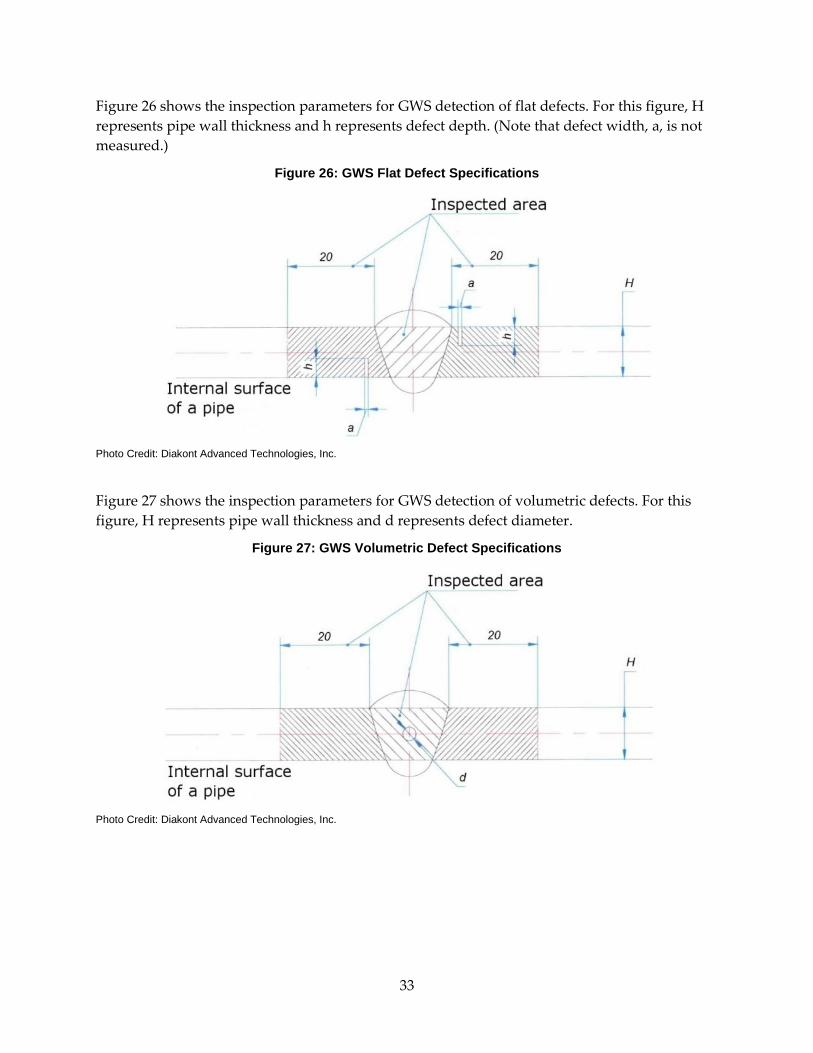
Figure 26 shows the inspection parameters for GWS detection of flat defects. For this figure, H represents pipe wall thickness and h represents defect depth. (Note that defect width, a, is not measured.)
Figure 26: GWS Flat Defect Specifications
Photo Credit: Diakont Advanced Technologies, Inc.
Figure 27 shows the inspection parameters for GWS detection of volumetric defects. For this figure, H represents pipe wall thickness and d represents defect diameter.
Figure 27: GWS Volumetric Defect Specifications
Photo Credit: Diakont Advanced Technologies, Inc.
33
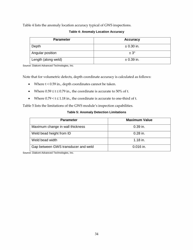
Table 4 lists the anomaly location accuracy typical of GWS inspections.
Table 4: Anomaly Location Accuracy
Parameter Accuracy
Depth ± 0.30 in.
Angular position ± 3°
Length (along weld) ± 0.39 in. Source: Diakont Advanced Technologies, Inc.
Note that for volumetric defects, depth coordinate accuracy is calculated as follows:
• Where t < 0.59 in., depth coordinates cannot be taken.
• Where 0.59 ≤ t ≤ 0.79 in., the coordinate is accurate to 50% of t.
• Where 0.79 < t ≤ 1.18 in., the coordinate is accurate to one-third of t.
Table 5 lists the limitations of the GWS module’s inspection capabilities.
Table 5: Anomaly Detection Limitations
Parameter Maximum Value
Maximum change in wall thickness 0.39 in.
Weld bead height from ID 0.28 in.
Weld bead width 1.18 in.
Gap between GWS transducer and weld 0.016 in. Source: Diakont Advanced Technologies, Inc.
34

Figure 28 shows how variations in wall thickness impact a GWS inspection. Note that surface defects or subsurface defects in an internal wall HAZ may not be detected if the pipe wall thickness varies by more than 0.118 in.
Figure 28: Wall Thickness Inspection Limitation
Photo Credit: Diakont Advanced Technologies, Inc.
Figure 29 shows the maximum weld size that the GWS can examine.
Figure 29: Defect Dimension Measurement Limitations
Photo Credit: Diakont Advanced Technologies, Inc.
35

6.3 Explanation of Field Data Inspection data is manually verified by an NDE Technician qualified through Diakont’s personnel qualification process before being presented to the pipeline operator client in the form of pipeline feature lists. Diakont data verification methods adhere to accepted industry standards, including the following:
• The European Pipeline Operators Forum (POF) Specifications 2009
• The American Petroleum Institute (API) In-line Inspection Systems Qualification Standard, API 1163
• Macaw’s Pipeline Defects
• The American Society for Mechanical Engineers (ASME) B31.8S-2004
• The American Society for Testing and Materials (ASTM) International E1774-96, Standard Guide for Electromagnetic Acoustic Transducers (EMATs)
• ASTM International E1816-07, Standard Practice for Ultrasonic Testing Using Electromagnetic Acoustic Transducer (EMAT) Techniques
See Appendix A for an explanation of data analysis methods and sample report contents.
36
CHAPTER 7: Commercialization 7.1 Technology Transfer Activities The deliverables produced by the execution of the project, including experimental results and lessons learned, are being made available to the public to maximize its beneficial impact. A technology transfer plan has been developed to ensure that the results of the project are disseminated to key stakeholders and decision makers.
The technology-transfer plan includes two main avenues for public dissemination:
• A description of the project, its rationale, and its execution as well as key experimental results are included in the main section of this report for public consumption. Project fact sheets will also be available with descriptions of key findings.
• Diakont routinely presents results of activities through presentations and panel discussions at various professional conferences, including the annual Pipeline Pigging & Integrity Management Conference, Unpiggable Pipeline Solutions Forum, and other topical conferences that discuss structural integrity in the energy industry.
The technology transfer plan also includes transferring the results of the project to key decision makers in potential commercialization partners. Diakont has prepared a list of potential commercialization partners, including the following:
• Public utility companies
• Petroleum storage and transportation companies
• Municipal water departments
• Power plant operators
Diakont has created a White Paper and promoted the technology at the API Inspection Summit, the PRCI trade show, and PPIM 2015. Fox and NBC affiliates in San Francisco featured the technology on their evening broadcasts; Diakont posted these videos on its company website and its YouTube channel.
37

Table 6 shows the Diakont technology transfer plan for GWS technology.
Table 6: Technology Transfer Plan
Component Method(s) Frequency
Website postings
• Post reports of relevant current innovations • Provide access to relevant media
As notable events occur
Trade show exhibits
Use exhibit booths to showcase inspection technologies at key industry trade shows.
At least ten trade show booths each year
Technical presentations
Provide presentations at industry trade shows and conferences.
At least one presentation per year
Source: Diakont Advanced Technologies, Inc.
7.2 Production Readiness Plan As part of the commercialization, inspection data and tool selection were structured to follow the processes and formats of API 1163 and API 1104. Diakont intends to work with API and the POF to update ILI reporting conventions to accommodate this new capability.
PHMSA maintains records of mechanical fitting failures in pipelines. Operators reported 27,270 fitting failures in natural gas pipelines in the United States between January 2011 and November 2014; the average reported manufacture date for failed components was 1979, with many operators simply listing the manufacture date as “unknown.” This average also includes many pipelines installed before effective weld-testing technology existed for manufacturers to perform effective quality-control. With so many pipelines of advanced or indeterminate age, Diakont’s GWS technology will be a key new tool in operators’ pipeline integrity management programs in order to reduce the likelihood of these failures.
Diakont’s RODIS crawlers have been used with other existing modules to successfully inspect hazardous liquid lines (e.g., crude, kerosene, diesel) for pipe wall defects. This proven delivery capability enables Diakont to offer operators GWS module inspections on these lines, extending the technology’s reach beyond natural gas to benefit other segments of the pipeline industry and further increase public safety.
In less than two years, Diakont has honed the GWS module from an experimental tool to commercially viable technology ready for live inspections. Diakont will use the technical information and the actual pipeline testing experience from this project to streamline future iterations of the tool for even more customer applications, including smaller diameter pipes and increased ability to navigate bends, and to optimize marketing efforts to serve more customers. Table 7 shows a preliminary five-year estimate for anticipated GWS inspections.
38

Table 7: Five-Year Preliminary GWS Inspection Budget
Year Estimated Inspection
Days
Estimated Revenue per Day
Estimated Revenue
Total Revenue
Generated
2015 4 $10,000 $40,000 $40,000
2016 8 $10,500 $84,000 $124,000
2017 16 $11,000 $176,000 $300,000
2018 20 $11,600 $232,000 $532,000
2019 22 $12,200 $268,400 $800,400 Source: Diakont Advanced Technologies, Inc.
This technology is also intended to be exported to other countries. Readying the technology for use elsewhere will require adherence to internationally-accepted standards as well as laws and regulations peculiar to given work locations. Diakont has proven the ability and desire to meet or exceed applicable requirements in order to offer the highest possible inspection quality. Opportunities to adapt to new challenges will improve GWS technology, inspection processes, and data analysis methods.
39

CHAPTER 8: Conclusion This project improved an experimental technology to the point of successful live demonstration and commercial availability. Diakont used their existing EMAT technology and RODIS inspection system to bring to market a reliable, accurate method of inspecting pipeline girth weld structural integrity.
The project began with a prototype GWS module, constructed according to years of experience with other structural integrity inspection methods and knowledge of the difficulties peculiar to weld inspection. This project helped Diakont engineers and technicians see the module through internal testing and quality control measures as well as the explosion-proof certification process, giving management the confidence to begin seeking external testing opportunities.
Once the GWS module was ready for external testing, PG&E provided test objects in controlled environments for use in demonstration inspections. Diakont inspection teams worked with PG&E personnel to inspect these test objects, analyze results, and optimize inspection methods.
These test results, combined with a successful pipe wall EMAT inspection in a difficult environment, gave PG&E the confidence to work with Diakont management to deploy the GWS module into a section of an active pipeline network. A Diakont inspection crew successfully deployed the module into this inspection area, gathering crucial data for PG&E’s pipeline integrity management program.
Diakont personnel will continue to fine-tune the GWS module and improve inspection methods to offer the best possible data gathering and analysis to customers. Engineering teams are also using key lessons learned during the GWS project to devise a method of long-seam weld inspection, continuing Diakont’s tradition of addressing pipeline integrity issues and providing unique services to operators worldwide.
40

GLOSSARY
Term Definition
ASME American Society of Mechanical Engineers
Anisotropic Exhibiting properties with different values when measured in different directions
API 1104 American Petroleum Institute Welding of Pipelines and Related Facilities Standard
API 1163 American Petroleum Institute In-Line Inspection Systems Qualification Standard
ASTM ASTM International, formerly the American Society for Testing and Materials
Bell hole A hole dug in compliance with OSHA standards to gain access to underground pipelines
Corrosion Per API 1163, the deterioration of a material that results from a reaction with its environment
CPR Critical Project Review
ECDA External corrosion direct assessment; a structural integrity management plan that examines pipelines and identifies potential external problems; a structured, multi-step evaluation defined under 49 CFR 192.925 that includes excavation
Electromechanical Of, relating to, or being a mechanical process or device actuated or controlled electrically; especially being a transducer for converting electrical energy to mechanical energy
EMAT Electromagnetic-acoustic transducer, a non-contact, non-destructive ultrasonic means of measuring pipe wall thickness
FT Frequency-time; this describes a two-dimensional graph that has frequency on one axis and time on the other, where the color of a point on the graph is defined by the time required to receive a signal
Girth weld Circumferential weld joining two joints of pipe
HAZ Heat-affected zone, the area of base metal surrounding a weld whose microstructure and properties have been altered by welding or heat-intensive cutting operations
41

Hoop stress Per ANSI B31.8, the stress in a pipe wall, acting circumferentially in a plan perpendicular to the longitudinal axis of the pipe and produced by the pressure of the fluid in the pipe
Hydrotesting (or hydro testing)
Testing of sections of a pipeline by filling the line with water and pressurizing it until the nominal hoop stresses in the pipe reach a specified value
ICDA Internal corrosion direct assessment; a structural integrity management plan that examines pipelines and identifies potential internal problems; a structured, multi-step evaluation defined under 49 CFR 192.927 that includes excavation
ILI In-line inspection, inspection of the pipeline from inside the line
Isotropic Exhibiting properties (as velocity of sound transmission) with the same values when measured along axes in all directions
Lamination Per API 1163, an internal metal separation creating layers generally parallel to the surface
Long-seam weld The longitudinal weld in the pipe, made at the pipe mill
Lorentz force The force on a charged particle moving through a region containing both electric and magnetic fields
Measurement accuracy
Per API 1163, the accuracy with which an anomaly dimension or characteristic is reported; typically expressed by a tolerance and a certainty, e.g., depth sizing accuracy for metal-loss is commonly expressed as ±10% of the wall thickness (the tolerance) 80% of the time (the certainty)
MFL Magnetic flux leakage, a magnetic method of non-destructive testing; typically used in a flow-driven pig
Multi-tool A single ILI tool that conducts inspections for multiple classes of anomalies
NPS Nominal pipe size
Piezoelectricity Electricity or electric polarity due to pressure
Pig A traditional flow-driven tool used to perform tasks inside a pipeline; typically built to perform a single task (e.g., cleaning pigs), as these are passive tools
Piggable A pipeline that can pass a standard in-line inspection tool
42
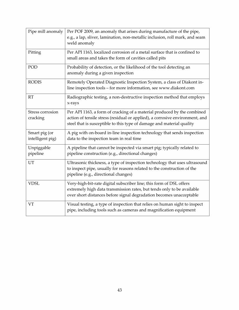
Pipe mill anomaly Per POF 2009, an anomaly that arises during manufacture of the pipe, e.g., a lap, sliver, lamination, non-metallic inclusion, roll mark, and seam weld anomaly
Pitting Per API 1163, localized corrosion of a metal surface that is confined to small areas and takes the form of cavities called pits
POD Probability of detection, or the likelihood of the tool detecting an anomaly during a given inspection
RODIS Remotely Operated Diagnostic Inspection System, a class of Diakont in-line inspection tools – for more information, see www.diakont.com
RT Radiographic testing, a non-destructive inspection method that employs x-rays
Stress corrosion cracking
Per API 1163, a form of cracking of a material produced by the combined action of tensile stress (residual or applied), a corrosive environment, and steel that is susceptible to this type of damage and material quality
Smart pig (or intelligent pig)
A pig with on-board in-line inspection technology that sends inspection data to the inspection team in real time
Unpiggable pipeline
A pipeline that cannot be inspected via smart pig; typically related to pipeline construction (e.g., directional changes)
UT Ultrasonic thickness, a type of inspection technology that uses ultrasound to inspect pipe, usually for reasons related to the construction of the pipeline (e.g., directional changes)
VDSL Very-high-bit-rate digital subscriber line; this form of DSL offers extremely high data transmission rates, but tends only to be available over short distances before signal degradation becomes unacceptable
VT Visual testing, a type of inspection that relies on human sight to inspect pipe, including tools such as cameras and magnification equipment
43

REFERENCES
American Petroleum Institute. API Standard 1163. In-line Inspection Systems Qualification Standard. Washington, D.C.: API Publishing Services, 2005.
Argent, Colin (editor). Macaw's Pipeline Defect Manual. Basingstoke: Yellow Pencil Marketing Co. Ltd., 2005.
ASTM International. Standard Practice for Ultrasonic Surface Testing Using Electromagnetic Acoustic Transducer (EMAT) Techniques. West Conshohocken: ASTM International, 2012.
Dearen, Jason and Joan Lowy. "Calif. pipeline blast probe finds weld defects.” Fuel Fix. http://fuelfix.com/blog/2011/01/21/calif-pipeline-blast-probe-finds-weld-defects/
Merriam-Webster. Merriam-Webster's Dictionary. http://www.merriam-webster.com.
NBC Bay Area. “PG&E Penalized $1.4 Billion for Violations Related to 2010 San Bruno Gas Pipeline Explosion.” http://www.nbcbayarea.com/news/local/PGE-Penalized-14-Billion-for-Violations-Related-to-2010-San-Bruno-Gas-Pipeline-Explosion-273617001.html
Pipeline Operator's Forum. Specifications and requirements for intelligent pig inspection of pipelines. http://www.pipelineoperators.org/publicdocs/POF_specs_2009.pdf.
The American Society of Mechanical Engineers. ASME Standard B31.8S. Managing System Integrity of Gas Pipelines. New York: The American Society of Mechanical Engineers, 2014.
U.S. Department of Transportation Pipeline and Hazardous Materials Safety Administration. Data & Statistics. http://www.phmsa.dot.gove/pipeline/library/data-stats.
44

APPENDIX A: Data A.1 Inspection Criteria Anomalies were classified in accordance with accepted industry standards. Length is measured axially, and width is measured circumferentially. The values provided are measured to the start of the anomaly, as shown in Figure 30.
Figure 30: Orientation and Measurement Convention
Photo Credit: Pipeline Operators Forum
A-1

Anomaly circumferential position is denoted in degrees, where 0 degrees corresponds to the top center. Circumferential positions provided are measured to the center of the anomaly. This measurement increases when moving clockwise while facing in the direction of the tool travel, as shown in Figure 31.
Figure 31: Degree Position Values of Circumferential Coordinates
A-2
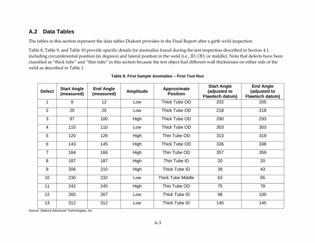
A.2 Data Tables The tables in this section represent the data tables Diakont provides in the Final Report after a girth weld inspection.
Table 8, Table 9, and Table 10 provide specific details for anomalies found during the test inspection described in Section 4.1, including circumferential position (in degrees) and lateral position in the weld (i.e., ID, OD, or middle). Note that defects have been classified as “thick tube” and “thin tube” in this section because the test object had different wall thicknesses on either side of the weld as described in Table 1.
Table 8: First Sample Anomalies – First Tool Run
Defect Start Angle (measured)
End Angle (measured) Amplitude Approximate
Position Start Angle (adjusted to
Flawtech datum)
End Angle (adjusted to
Flawtech datum) 1 9 12 Low Thick Tube OD 202 205
2 25 25 Low Thick Tube OD 218 218
3 97 100 High Thick Tube OD 290 293
4 110 110 Low Thick Tube OD 303 303
5 120 126 High Thin Tube OD 313 319
6 143 145 High Thick Tube OD 336 338
7 164 166 High Thin Tube OD 357 359
8 187 187 High Thin Tube ID 20 20
9 206 210 High Thick Tube ID 39 43
10 230 232 Low Thick Tube Middle 63 65
11 242 245 High Thin Tube OD 75 78
12 265 267 Low Thick Tube ID 98 100
13 312 312 Low Thick Tube ID 145 145 Source: Diakont Advanced Technologies, Inc.
A-3

Table 9: First Sample Anomalies – Second Tool Run
Defect Start Angle (measured)
End Angle (measured) Amplitude Approximate
Position Start Angle (adjusted to
Flawtech datum)
End Angle (adjusted to
Flawtech datum) 1 27 30 -4 Thick Tube OD 201 204
2 42 42 -5 Thick Tube OD 216 216
3 118 121 0 Thick Tube OD 292 295
4 131 131 -4 Thick Tube OD 305 305
5 141 144 -2 Thin Tube OD 315 318
6 164 166 -2 Thick Tube OD 338 340
7 182 184 -3 Thin Tube OD 356 358
8 204 204 -3 Thin Tube ID 18 18
9 223 226 -1 Thick Tube ID 37 40
10 244 247 -1 Thick Tube Middle 58 61
11 257 260 -1 Thin Tube OD 71 74
12 278 281 -5 Thick Tube ID 92 95
13 327 328 -5 Thick Tube ID 141 142 Source: Diakont Advanced Technologies, Inc.
A-4
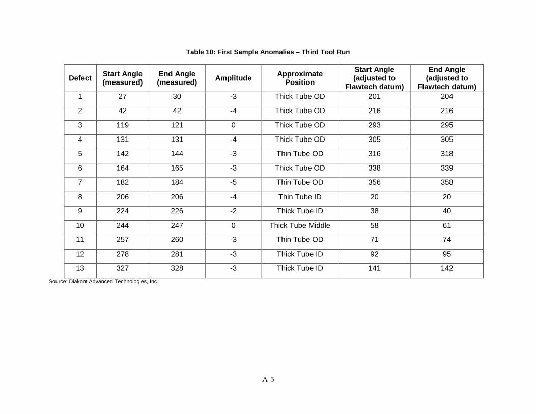
Table 10: First Sample Anomalies – Third Tool Run
Defect Start Angle (measured)
End Angle (measured) Amplitude Approximate
Position Start Angle (adjusted to
Flawtech datum)
End Angle (adjusted to
Flawtech datum) 1 27 30 -3 Thick Tube OD 201 204
2 42 42 -4 Thick Tube OD 216 216
3 119 121 0 Thick Tube OD 293 295
4 131 131 -4 Thick Tube OD 305 305
5 142 144 -3 Thin Tube OD 316 318
6 164 165 -3 Thick Tube OD 338 339
7 182 184 -5 Thin Tube OD 356 358
8 206 206 -4 Thin Tube ID 20 20
9 224 226 -2 Thick Tube ID 38 40
10 244 247 0 Thick Tube Middle 58 61
11 257 260 -3 Thin Tube OD 71 74
12 278 281 -3 Thick Tube ID 92 95
13 327 328 -3 Thick Tube ID 141 142 Source: Diakont Advanced Technologies, Inc.
A-5

Table 11, Table 12, and Table 13 show areas of signal loss from each tool run on the test object described in Section 4.1. Signal loss may be caused by impediments on the pipe wall (e.g., corrosion, loose debris) or by pipe wall defects (e.g., an area with non-metallic inclusions).
Table 11: Girth Weld Areas of Signal Loss – First Tool Run
Start Angle (measured)
End Angle (measured)
Start Angle (adjusted to Flawtech datum)
End Angle (adjusted to Flawtech datum) Note
164 171 357 4 Seam weld not ground-down
291 300 124 133 Seam weld not ground-down Source: Diakont Advanced Technologies, Inc.
Table 12: Girth Weld Areas of Signal Loss – Second Tool Run
Start Angle (measured)
End Angle (measured)
Start Angle (adjusted to Flawtech datum)
End Angle (adjusted to Flawtech datum) Note
183 190 357 4 Seam weld not ground-down
306 313 120 127 Seam weld not ground-down Source: Diakont Advanced Technologies, Inc.
Table 13: Girth Weld Areas of Signal Loss – Third Tool Run
Start Angle (measured)
End Angle (measured)
Start Angle (adjusted to Flawtech datum)
End Angle (adjusted to Flawtech datum) Note
183 190 357 4 Seam weld not ground-down
306 313 120 127 Seam weld not ground-down Source: Diakont Advanced Technologies, Inc.
A-6

Table 14, Table 15, and Table 16 provide specific details for anomalies found during the test inspection described in Section 4.2, including circumferential position (in degrees) and lateral position in the weld (i.e., ID, OD, or middle). Note that defects have been classified as “thick tube” and “thin tube” in this section because the test object had different wall thicknesses on either side of the weld as described in Table 2.
Table 14: Second Sample Anomalies – First Tool Run
Defect Start Angle (deg)
End Angle (deg)
Length (deg)
Approximate Position
Amplitude (dB) Notes
1 5 11 6 Thick pipe OD -1 Detected among signals reflected from the weld bead
2 14 15 1 Thick pipe OD -2 Detected among signals reflected from the weld bead
3 62 64 1 Thick pipe MD -1 Detected among signals reflected from the weld bead
4 91 101 10 Thick pipe OD -2 Detected among signals reflected from the weld bead
5 110 112 2 Thick pipe OD -1 Detected among signals reflected from the weld bead
6 146 148 2 Thick pipe ID 0 -
7 196 199 3 Thick pipe MD 0 Detected among signals reflected from the weld bead
8 213 214 1 Weld MD -1 -
9 227 227 0 Weld OD -1 -
10 241 241 0 Thin pipe ID -2 -
11 268 272 4 Weld OD -3 -
12 281 282 1 Thick pipe OD -1 -
A-7

Defect Start Angle (deg)
End Angle (deg)
Length (deg)
Approximate Position
Amplitude (dB) Notes
13 295 296 1 Thick pipe OD -1 -
14 309 310 1 Thick pipe ID -1 -
15 326 328 2 Weld ID 0 -
16 341 342 1 Weld OD 0 -
17 356 358 2 Thick pipe ID 0 - Source: Diakont Advanced Technologies, Inc.
Table 15: Second Sample Anomalies – Second Tool Run
Defect Start Angle (deg)
End Angle (deg)
Length (deg)
Approximate Position
Amplitude (dB) Notes
1 6 10 4 Thick pipe OD -2 Detected among signals reflected from the weld bead
2
N/A Thick pipe OD Detected among signals reflected from the weld bead; determined during this tool run to be below the reporting threshold (in dB)
3 61 61 0 Thick pipe MD -3 Detected among signals reflected from the weld bead
4 88 98 10 Thick pipe OD 0 Detected among signals reflected from the weld bead
5 104 108 4 Thick pipe OD -1 Detected among signals reflected from the weld bead
6 145 147 2 Thick pipe ID -1 -
7 197 198 1 Thick pipe MD 0 Detected among signals reflected from the weld bead
A-8

Defect Start Angle (deg)
End Angle (deg)
Length (deg)
Approximate Position
Amplitude (dB) Notes
8 214 215 1 Weld MD 0 -
9 228 229 1 Weld OD -2 -
10 242 243 1 Thin pipe ID -2 -
11 268 269 1 Weld OD -3 -
12 283 284 1 Thick pipe OD -1 -
13 297 297 0 Thick pipe OD 0 -
14 310 310 0 Thick pipe ID -3 -
15 327 328 1 Weld ID 0 -
16 341 342 1 Weld OD 0 -
17 356 358 2 Thick pipe ID 0 - Source: Diakont Advanced Technologies, Inc.
Table 16: Second Sample Anomalies – Third Tool Run
Defect Start Angle (deg)
End Angle (deg)
Length (deg)
Approximate Position
Amplitude (dB) Notes
1 9 10 1 Thick pipe OD -1 Detected among signals reflected from the weld bead
2
N/A Thick pipe OD Detected among signals reflected from the weld bead; determined
during this tool run to be below the reporting threshold (in dB)
3 63 64 2 Thick pipe MD -5 Detected among signals reflected from the weld bead
A-9
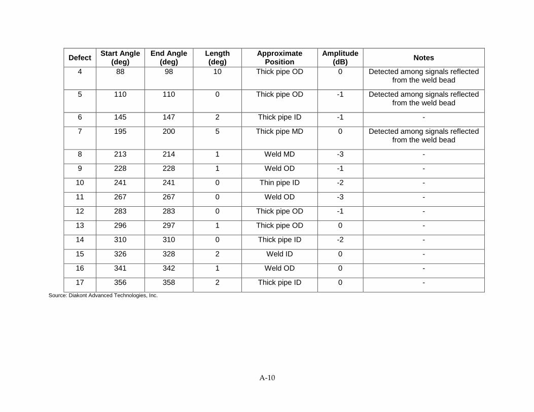
Defect Start Angle (deg)
End Angle (deg)
Length (deg)
Approximate Position
Amplitude (dB) Notes
4 88 98 10 Thick pipe OD 0 Detected among signals reflected from the weld bead
5 110 110 0 Thick pipe OD -1 Detected among signals reflected from the weld bead
6 145 147 2 Thick pipe ID -1 -
7 195 200 5 Thick pipe MD 0 Detected among signals reflected from the weld bead
8 213 214 1 Weld MD -3 -
9 228 228 1 Weld OD -1 -
10 241 241 0 Thin pipe ID -2 -
11 267 267 0 Weld OD -3 -
12 283 283 0 Thick pipe OD -1 -
13 296 297 1 Thick pipe OD 0 -
14 310 310 0 Thick pipe ID -2 -
15 326 328 2 Weld ID 0 -
16 341 342 1 Weld OD 0 -
17 356 358 2 Thick pipe ID 0 - Source: Diakont Advanced Technologies, Inc.
A-10
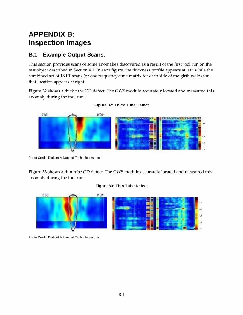
APPENDIX B: Inspection Images B.1 Example Output Scans. This section provides scans of some anomalies discovered as a result of the first tool run on the test object described in Section 4.1. In each figure, the thickness profile appears at left, while the combined set of 18 FT scans (or one frequency-time matrix for each side of the girth weld) for that location appears at right.
Figure 32 shows a thick tube OD defect. The GWS module accurately located and measured this anomaly during the tool run.
Figure 32: Thick Tube Defect
Photo Credit: Diakont Advanced Technologies, Inc.
Figure 33 shows a thin tube OD defect. The GWS module accurately located and measured this anomaly during the tool run.
Figure 33: Thin Tube Defect
Photo Credit: Diakont Advanced Technologies, Inc.
B-1

Figure 34 shows a weld OD defect. This defect was accurately characterized during the tool run, but fell below the initial length threshold; it was therefore not reported as a defect until the threshold was adjusted as described in Section 4.1.
Figure 34: Weld Defect
Photo Credit: Diakont Advanced Technologies, Inc.
B.2 Example Pipe Photos Figure 35 shows excess weld reinforcement, i.e., the weld bead rises too high from the material surface. According to Macaw’s Pipeline Defect Manual, “excess cap height usually only has structural significance in a fatigue situation due to increased stress concentration at the weld cap-to-pipe intersection” (59), making this a key defect to detect and repair in an active pipeline.
Figure 35: Excess Reinforcement
Photo Credit: Macaw’s Pipeline Defect Manual
B-2
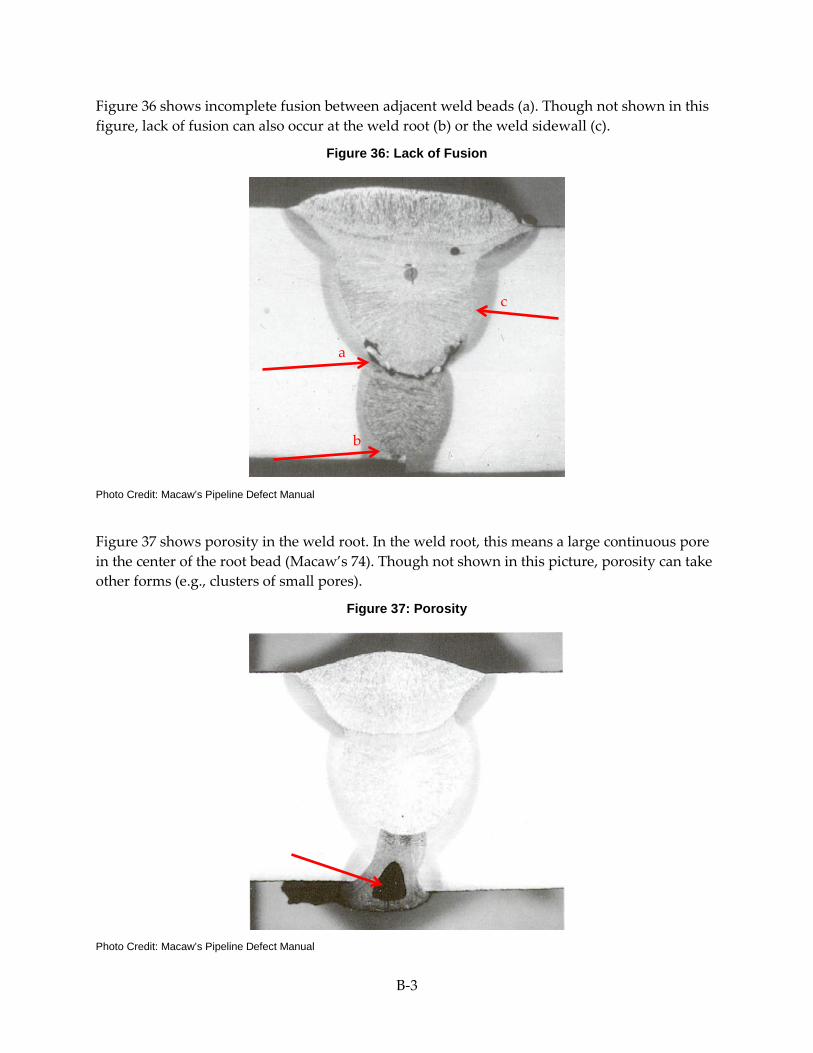
Figure 36 shows incomplete fusion between adjacent weld beads (a). Though not shown in this figure, lack of fusion can also occur at the weld root (b) or the weld sidewall (c).
Figure 36: Lack of Fusion
Photo Credit: Macaw’s Pipeline Defect Manual
Figure 37 shows porosity in the weld root. In the weld root, this means a large continuous pore in the center of the root bead (Macaw’s 74). Though not shown in this picture, porosity can take other forms (e.g., clusters of small pores).
Figure 37: Porosity
Photo Credit: Macaw’s Pipeline Defect Manual
b
a
c
B-3

Figure 38 shows cracking in the weld root HAZ (a). Though not shown in the figure, cracking can also occur in the weld cap HAZ (b) or in the weld metal itself (c).
Figure 38: Cracking
Photo Credit: Macaw’s Pipeline Defect Manual
c b
a
B-4