i.mx 8m family - boot time measurements methodology
TRANSCRIPT

1 IntroductionThis document presents a possible approach to measure the boot time on thei.MX 8M platforms using the GPIO pins.
The main objectives of this document are as follows:
• Modifying the bootloader and system image for measuring
• Setting up the board and the external logic analyzer tool
• Achieving short boot times
1.1 Software environmentLinux BSP release 5.4.70_2.3.0 is used to perform all the measurements. The imx-image-core Yocto image is used duringthe experiments.
1.2 Hardware setup and equipment• Development kits:
— NXP i.MX 8MQ EVK LPDDR4
— NXP i.MX 8MP EVK LPDDR4
— NXP i.MX 8MM EVK LPDDR4
— NXP i.MX 8MN EVK LPDDR4
• Micro SD card. SanDisk Ultra 32 GB Micro SDHC I Class 10 is used for the current experiment.
• Micro-USB cable for the debug port.
• USB Type-C cable for data transfer.
• Logic analyzer with the following minimum requirements to measure the times: 4 channels and 10 MS/s. Saleae Logic 8 isused for the current experiment.
• Breadboard and FPC to 60x0.5 Extension Board (only for i.MX8 MQ).
2 General descriptionThis section describes the general procedure that must be performed to obtain a baseline measurement for a clean system (withno startup optimizations).
2.1 Choosing the GPIO pin for measurementUse a general-purpose pin to generate a pulse signal at different booting phases. The desired GPIO pin is ideally chosen fromthose that are not used in either the bootloader or Linux; this can be checked in the associated device tree.
If this is not possible, disable the peripheral module that uses the pin in the next step. It is highly recommended to choose a pinfrom the expansion connector on the board.
Contents
1 Introduction......................................12 General description......................... 13 Examples.........................................24 Further optimizations.....................375 References....................................476 Revision history.............................47
AN13369i.MX 8M Family - Boot Time Measurements MethodologyRev. 0 — 07 September 2021 Application Note

2.2 Updating the device tree at the bootloader and Linux levelAfter you choose the desired pin, make some modifications at the device-tree level.
Firstly, the functionalities of the desired pin are checked to find out the macros associated with the GPIO functionality. The headerfiles are at different location, depending on the board used.
Secondly, if a pin is used by some other peripheral modules, disable the respective module. This is done by setting the statusproperty to “disabled” in the configuration info for that peripheral module.
Thirdly, the adequate pin muxing is defined in the pinctrl_hog section, using the GPIO macro for the chosen pin and thepad-configuration values (IOMUXC_SW_PAD_CTL_PAD_*).
2.3 Adding the first pulse generatorThe first period measured is between the board POR and the execution of the board_init_f function of the SPL part of thebootloader. To generate a pulse, configure the pin as the output. After this, you can drive the pin high for a short time and thenyou can drive it low. You can do this without delay, because only the rising edge of the pulse is necessary.
2.4 Adding the second pulse generatorThe second period measured is between the execution of the board_init_f function of the SPL part of the bootloader and beforeloading the kernel image from the U-Boot console. You can toggle that here using the U-Boot GPIO commands, which can bewritten in the board configuration file, located in the /include/configs folder.
2.5 Adding the third pulse generatorThe third period measured is between loading the kernel image from the U-Boot console and starting the psplash program, whichuses the frame buffer to show the relevant content on the display. To change the GPIO output state, add the libgpiod packageto the psplash Yocto recipe. After adding the libgpiod package, the gpiod functions are added to the psplash code to generatea pulse right before the program uses the frame buffer for the first time.
2.6 Measuring the total time with the logic analyzerThe measurement stage can begin after building and flashing both the bootloader and Linux image to the board.
The boot-time is measured by starting the recording mode on the logic analyzer software and applying the reset button on theboard. The recording stops after the third rising edge on the chosen GPIO pin. The elapsed boot time is the time between the risingedge of the nRST signal and the third rising edge of the GPIO pin.
3 Examples
3.1 i.MX 8M QuadChoosing the pins
The chosen pin is the 19th pin on the J1801 expansion connector on the specified board. In the schematics for the baseboard,the pin is used for the SAI 1 peripheral with the SAI1_RXFS function. Searching the specified pad in the reference manual for theassociated pin returns an alternate function of GPIO4_IO[0].
NXP SemiconductorsExamples
i.MX 8M Family - Boot Time Measurements Methodology, Rev. 0, 07 September 2021Application Note 2 / 48
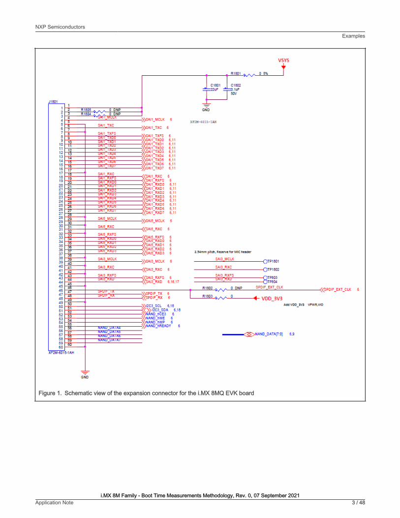
Figure 1. Schematic view of the expansion connector for the i.MX 8MQ EVK board
NXP SemiconductorsExamples
i.MX 8M Family - Boot Time Measurements Methodology, Rev. 0, 07 September 2021Application Note 3 / 48

Figure 2. Associated mux control register for the chosen pad (SAI1_RXFS)
Updating the U-Boot Device tree
To get the necessary files, issue the following command:
$ bitbake -f -c unpack imx-boot
NXP SemiconductorsExamples
i.MX 8M Family - Boot Time Measurements Methodology, Rev. 0, 07 September 2021Application Note 4 / 48

To update the device tree, find out the macro associated to the desired functionality. This informationis in the <yocto_build_dir>/tmp/work/imx8mqevk-poky-linux/u-boot-imx/<specified_git_folder>/git/include/dt-bindings/pinctrl/pins-imx8mq.h file. However, the use of this macro is not enough for an adequate pin mux setup, becauseit requires a sixth value, which represents the pad configuration.
#define MX8MQ_IOMUXC_SAI1_RXFS_SAI1_RX_SYNC 0x15C 0x3C4 0x4C4 0x0 0x0#define MX8MQ_IOMUXC_SAI1_RXFS_SAI5_RX_SYNC 0x15C 0x3C4 0x4E4 0x1 0x1#define MX8MQ_IOMUXC_SAI1_RXFS_CORESIGHT_TRACE_CLK 0x15C 0x3C4 0x000 0x4 0x0#define MX8MQ_IOMUXC_SAI1_RXFS_GPIO4_IO0 0x15C 0x3C4 0x000 0x5 0x0
The associated DTS file for the i.MX 8MQ EVK board (<yocto_build_dir>/tmp/work/imx8mqevk-poky-linux/u-boot-imx/<specified_git_folder>/git/arch/arm/dts/imx8mq-evk.dts) shows that the pin is not used, so there is nothing to disable.To use the pin with the GPIO functionality, add the following pin muxing in iomuxc.
pinctrl_hog_1: hoggrp-1 { fsl,pins = < MX8MQ_IOMUXC_SAI1_RXFS_GPIO4_IO0 0x16 >; };
The 0x16 configuration is based on the following pad settings in the IOMUXC_SW_PAD_CTL_PAD_SAI1_RXFS register:
• Drive Strength Field: 45_OHM
• Slew Rate Field: Fast
• Open Drain Enable field: Disabled
• Pull Up Enable Field: Disabled
• Schmitt trigger Enable Field: Disabled
• Lvttl Enable Field: Disabled
Updating the Linux device tree
To update the device tree, find out the macro associated to the desired functionality. This information is in the<yocto_build_dir>/tmp/work-shared/imx8mqevk/kernel_source/arch/arm64/boot/dts/freescale/pins-imx8mq.h file.However, the use of this macro is not enough for an adequate pin mux setup, because it requires a sixth value, which representsthe pad configuration.
#define MX8MQ_IOMUXC_SAI1_RXFS_SAI1_RX_SYNC 0x15C 0x3C4 0x4C4 0x0 0x0#define MX8MQ_IOMUXC_SAI1_RXFS_SAI5_RX_SYNC 0x15C 0x3C4 0x4E4 0x1 0x1#define MX8MQ_IOMUXC_SAI1_RXFS_CORESIGHT_TRACE_CLK 0x15C 0x3C4 0x000 0x4 0x0#define MX8MQ_IOMUXC_SAI1_RXFS_GPIO4_IO0 0x15C 0x3C4 0x000 0x5 0x0
The associated DTS file for the i.MX 8MQ EVK (<yocto_build_dir>/tmp/work-shared/imx8mqevk/kernel_source/arch/arm64/boot/dts/freescale/imx8mq-evk.dts) shows that the pin is already used with the SAI1 functionality. Change the statusproperty for the SAI1 from “okay” to “disabled”.
&sai1 { pinctrl-names = "default", "pcm_b2m", "dsd"; pinctrl-0 = <&pinctrl_sai1_pcm>; pinctrl-1 = <&pinctrl_sai1_pcm_b2m>; pinctrl-2 = <&pinctrl_sai1_dsd>; assigned-clocks = <&clk IMX8MQ_CLK_SAI1>; assigned-clock-parents = <&clk IMX8MQ_AUDIO_PLL1_OUT>; assigned-clock-rates = <49152000>; clocks = <&clk IMX8MQ_CLK_SAI1_IPG>, <&clk IMX8MQ_CLK_DUMMY>, <&clk IMX8MQ_CLK_SAI1_ROOT>, <&clk IMX8MQ_CLK_DUMMY>, <&clk IMX8MQ_CLK_DUMMY>, <&clk IMX8MQ_AUDIO_PLL1_OUT>, <&clk IMX8MQ_AUDIO_PLL2_OUT>; clock-names = "bus", "mclk0", "mclk1", "mclk2", "mclk3", "pll8k", "pll11k";
NXP SemiconductorsExamples
i.MX 8M Family - Boot Time Measurements Methodology, Rev. 0, 07 September 2021Application Note 5 / 48

fsl,sai-multi-lane; fsl,dataline,dsd = <0 0xff 0xff 2 0xff 0x11>; dmas = <&sdma2 8 25 0>, <&sdma2 9 25 0>; status = "disabled"; }
To use the pin with the GPIO functionality, add the following pin muxing to iomuxc. If the chosen pad has another pin muxconfiguration, replace the respective pin muxing with the following to successfully generate the pulse in Linux:
pinctrl_hog: hoggrp { fsl,pins = < MX8MQ_IOMUXC_NAND_READY_B_GPIO3_IO16 0x19 MX8MQ_IOMUXC_NAND_WE_B_GPIO3_IO17 0x19 MX8MQ_IOMUXC_NAND_WP_B_GPIO3_IO18 0x19 MX8MQ_IOMUXC_GPIO1_IO08_GPIO1_IO8 0xd6 MX8MQ_IOMUXC_GPIO1_IO00_ANAMIX_REF_CLK_32K 0x16 MX8MQ_IOMUXC_SAI1_RXFS_GPIO4_IO0 0x16 >; };
Adding the first pulse generator in <yocto_build_dir>/tmp/work/imx8mqevk-poky-linux/u-boot-imx/<specified_git_folder>/git/board/freescale/imx8mq_evk/spl.c
Firstly, declare a macro containing the pair of GPIO group and GPIO pin in the file:
#define TIMED_GPIO IMX_GPIO_NR(4, 0)
Secondly, you need a macro to use a pad as a GPIO. In this case, it already exists:
#define USDHC_GPIO_PAD_CTRL (PAD_CTL_PUE | PAD_CTL_DSE1)
Now you can add the pulse generation code in the board_init_f function, after the BSS clearing part:
void board_init_f(ulong dummy) {int ret;/* Clear the BSS. */memset(__bss_start, 0, __bss_end - __bss_start);gpio_request(TIMED_GPIO, "timed_gpio");gpio_direction_output(TIMED_GPIO, 1);gpio_direction_output(TIMED_GPIO, 0);arch_cpu_init();
Adding the second pulse generator in <yocto_build_dir>/tmp/work/imx8mqevk-poky-linux/u-boot-imx/<specified_git_folder>/git/include/configs/imx8mq_evk.h
The commands responsible for toggling the pin are added in the environment variables for the bootloader, at the load imageproperty. The pin is set before loading the image and reset afterwards:
“loadimage=gpio set GPIO4_0;fatload mmc ${mmcdev}:${mmcpart} ${loadaddr} ${image};gpio clear GPIO4_0\0” \
To automate the process, create a patch which contains the U-Boot modifications in the spl.c, imx8mq-evk.dts, andimx8mq_evk.h files. Add the details after the last commands that describe the nature of the patch:
$ git add board/freescale/imx8mq_evk/spl.c$ git add arch/arm/dts/imx8mq-evk.dts$ git add include/configs/imx8mq_evk.h$ git commit -s$ git format-patch HEAD~1
NXP SemiconductorsExamples
i.MX 8M Family - Boot Time Measurements Methodology, Rev. 0, 07 September 2021Application Note 6 / 48

Copy the resulting patch to the following location: <yocto_dir>/imx-yocto-bsp/sources/meta-imx/meta-bsp/recipes-bsp/u-boot/u-boot-imx. Add the name of the patch into the source location identifier in the Yocto recipe for U-Boot (<yocto_dir>/imx-yocto-bsp/sources/meta-imx/meta-bsp/recipes-bsp/u-boot/u-boot-imx_2020.04.bb):
SRC_URI = " ...\file://<patch_name>.patch \"
To check that the patch works after the modifications, apply the following commands, after which the files should contain thefollowing changes:
$ bitbake -f -c clean u-boot-imx$ bitbake u-boot-imx$ bitbake imx-boot
Adding the third pulse generator
For this stage, modify the Yocto recipe extension for psplash so that it can fetch the additional libgpiod library necessary for thetoggling of the GPIO (<yocto_dir>/sources/meta-imx/meta-bsp/recipes-core/psplash/psplash_git.bbappend):
DEPENDS = "libgpiod" RDEPENDS_${PN} = "libgpiod"RDEPENDS_${PN}-dev = "libgpiod"
To get the necessary psplash files, issue the following command:
$ bitbake -f -c unpack psplash
After fetching the necessary files, the makefile (<yocto_build_dir>/tmp/work/aarch64-poky-linux/psplash/<specified_git_folder>/git/Makefile.am) is modified to include the lgpiod:
AM_CFLAGS = $(GCC_FLAGS) -D_GNU_SOURCE -lgpiodGCC_FLAGS := $(GCC_FLAGS) -Lusr/lib -Iusr/include -lgpiodLD_FLAGS = $(LD_FLAGS) -lgpiod
Modify the source code (<yocto_build_dir>/tmp/work/aarch64-poky-linux/psplash/<specified_git_folder>/git/psplash.c). The first step is to include the library:
#include "gpiod.h"
In the main function, declare some additional variables responsible for selecting the bank and the line for the GPIO. The banksare zero-indexed, so the number of the GPIO bank must be decremented by one:
struct gpiod_chip *chip;struct gpiod_line *line;int gpio_line = 0;char dev[] = "/dev/gpiochip3";
Before sending the first command to the frame buffer (clearing the background), the program should acquire control of the pin,toggle it, and release it.
chip = gpiod_chip_open(dev); if (!chip) return -1; line = gpiod_chip_get_line(chip, gpio_line); if (!line) { gpiod_chip_close(chip); return -1; } req = gpiod_line_request_output(line, "SIGNAL", 2); if (req) { gpiod_chip_close(chip); return -1; } if (gpiod_line_set_value(line, 1) != 0){ printf("Impossible to change line %d value to %d \n", gpio_line, 1); gpiod_chip_close(chip); return -1; } if (gpiod_line_set_value(line, 0) != 0){
NXP SemiconductorsExamples
i.MX 8M Family - Boot Time Measurements Methodology, Rev. 0, 07 September 2021Application Note 7 / 48

printf("Impossible to change line %d value to %d \n", gpio_line, 0); gpiod_chip_close(chip); return -1; } gpiod_line_release(line); gpiod_chip_close(chip);
After applying all the modifications, build the psplash and the image using the following commands:
$ bitbake psplash$ bitbake imx-image-core
To automate this process, create a patch which contains the modifications in the Makefile.am and psplash.c files. Add the detailsafter the last commands describing the nature of the patch:
$ git add Makefile.am$ git add psplash.c$ git commit -s$ git format-patch HEAD~1
The resulting patch is then copied to the following location: <yocto_dir>/imx-yocto-bsp/sources/meta-imx/meta-bsp/recipes-core/psplash/files. The name of the patch is then added into the source location identifier in the Yocto Recipeextension for psplash (<yocto_dir>/sources/meta-imx/meta-bsp/recipes-core/psplash/psplash_git.bbappend).
SRC_URI += " \ file://psplash-start.service \ file://psplash-basic.service \ file://psplash-network.service \ file://psplash-quit.service \ file://<patch_name>.patch \ "
To check that the patch works after the modifications, apply the following commands, after which the psplash.c and Makefile.amfiles should contain the following changes:
$ bitbake -f -c clean psplash$ bitbake psplash$ bitbake imx-image-core
Measuring the total time with the logic analyzer
This part starts by setting up all the preliminary connections, such as the power supply, debug port, download port, and MIPI-DSIto HDMI connections. If the HDMI display is not connected and functional, the psplash pulse generation does not work, becauseno frame buffers exist.
Build both the bootloader and Linux image using bitbake. After that, they are written to the board using the UUU program, in whichyou can choose between writing to the on-board eMMC or the SD card.
The measuring stand is set up by connecting the logic analyzer to the board. The nRST signal is used as a starting reference andit is on the JTAG connector at pin 10.
NXP SemiconductorsExamples
i.MX 8M Family - Boot Time Measurements Methodology, Rev. 0, 07 September 2021Application Note 8 / 48
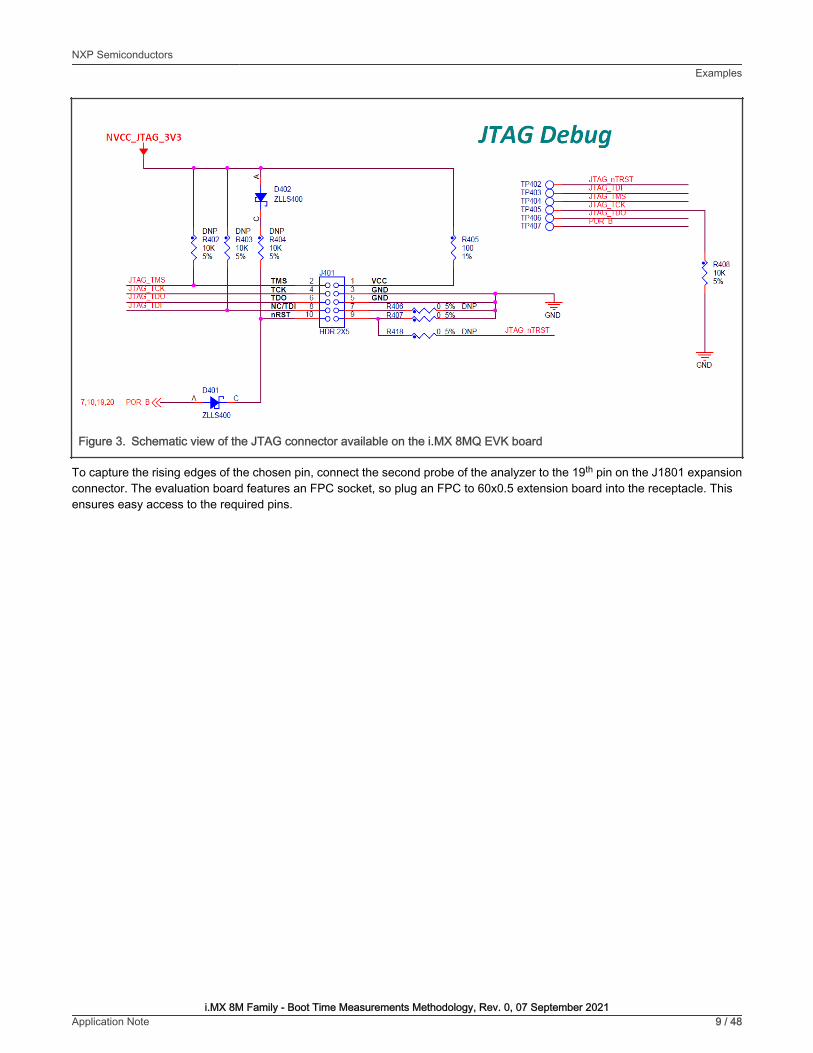
Figure 3. Schematic view of the JTAG connector available on the i.MX 8MQ EVK board
To capture the rising edges of the chosen pin, connect the second probe of the analyzer to the 19th pin on the J1801 expansionconnector. The evaluation board features an FPC socket, so plug an FPC to 60x0.5 extension board into the receptacle. Thisensures easy access to the required pins.
NXP SemiconductorsExamples
i.MX 8M Family - Boot Time Measurements Methodology, Rev. 0, 07 September 2021Application Note 9 / 48

Figure 4. Measurement setup on the i.MX 8MQ EVK board
After checking that both probes are referenced to the board’s ground, start the logic analyzer software, where you can set up theprobe parameters and the time frame.
Configure the board to start in the internal development mode, boot from the desired storage space, and then power it on. Afterthe psplash screen disappears, press the reset button on the board and start the recording on the logic analyzer software.
You should see a rising edge on the nRST pin, followed by three pulses on the chosen pin. At this moment, stop the recordingand place the measurement flags to find out the time for each phase. The boot time of the board in this configuration results fromthe sum of the elapsed time for each stage.
NXP SemiconductorsExamples
i.MX 8M Family - Boot Time Measurements Methodology, Rev. 0, 07 September 2021Application Note 10 / 48

Figure 5. Measurements on the boot-time for i.MX 8MQ EVK board
3.2 i.MX 8M PlusChoosing the pins
The chosen pin is the 24th pin on the J21 expansion connector on the specified board. In the schematics for the baseboard, thepin is used for the ECSPI 2 peripheral with the ECSPI2_SS0 function. Searching the specified signal in the reference manual forthe associated pin returns an alternate function of GPIO5_IO[13].
NXP SemiconductorsExamples
i.MX 8M Family - Boot Time Measurements Methodology, Rev. 0, 07 September 2021Application Note 11 / 48
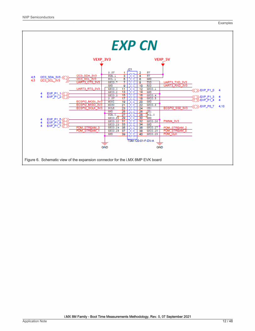
Figure 6. Schematic view of the expansion connector for the i.MX 8MP EVK board
NXP SemiconductorsExamples
i.MX 8M Family - Boot Time Measurements Methodology, Rev. 0, 07 September 2021Application Note 12 / 48

Figure 7. Associated mux control register for the chosen pad (ECSPI2_SS0)
Updating the U-Boot device tree
Issue the following command to get the necessary files:
$ bitbake -f -c unpack imx-boot
To update the device tree, find out the macro associated to the desired functionality. This information isin the <yocto_build_dir>/tmp/work/imx8mpevk-poky-linux/u-boot-imx/<specified_git_folder>/git/arch/arm/dts/
NXP SemiconductorsExamples
i.MX 8M Family - Boot Time Measurements Methodology, Rev. 0, 07 September 2021Application Note 13 / 48

imx8mp-pinfunc.h file. However, the use of this macro is not enough for an adequate pin mux setup, because it requires a sixthvalue, which represents the pad configuration.
#define MX8MP_IOMUXC_ECSPI2_SS0__ECSPI2_SS0 0x1FC 0x45C 0x574 0x0 0x1#define MX8MP_IOMUXC_ECSPI2_SS0__UART4_DCE_RTS 0x1FC 0x45C 0x5FC 0x1 0x3#define MX8MP_IOMUXC_ECSPI2_SS0__UART4_DTE_CTS 0x1FC 0x45C 0x000 0x1 0x0#define MX8MP_IOMUXC_ECSPI2_SS0__I2C4_SDA 0x1FC 0x45C 0x5C0 0x2 0x4#define MX8MP_IOMUXC_ECSPI2_SS0__CCM_CLKO2 0x1FC 0x45C 0x000 0x4 0x0#define MX8MP_IOMUXC_ECSPI2_SS0__GPIO5_IO13 0x1FC 0x45C 0x000 0x5 0x0
The associated DTS file for the i.MX 8MP EVK board (<yocto_build_dir>/tmp/work/imx8mpevk-poky-linux/u-boot-imx/<specified_git_folder>/git/arch/arm/dts/imx8mp-evk.dts) shows that the pin is not used, because there is nothing todisable. To use the pin with the GPIO functionality, add the following pin muxing in iomuxc:
pinctrl_hog: hoggrp { fsl,pins = < MX8MP_IOMUXC_ECSPI2_SS0__GPIO5_IO1 0x16 >; };
The 0x16 configuration is based on the following pad settings in the IOMUXC_SW_PAD_CTL_PAD_ECSPI2_SS0 register:
• Drive Strength Field: DSE_X6
• Slew Rate Field: Fast
• Open Drain Enable field: Disabled
• Pull Up/Down Config Field: Weak pull-down
• Input Select Field: CMOS
• Pull Select Field: Pull Disabled
Updating the Linux device tree
To update the device tree, find out the macro associated to the desired functionality. This information is in the<yocto_build_dir>/tmp/work-shared/imx8mpevk/kernel_source/arch/arm64/boot/dts/freescale/imx8mp-pinfunc.hfile. However, the use of this macro is not enough for an adequate pin mux setup, because it requires a sixth value, whichrepresents the pad configuration.
#define MX8MP_IOMUXC_ECSPI2_SS0__ECSPI2_SS0 0x1FC 0x45C 0x574 0x0 0x1#define MX8MP_IOMUXC_ECSPI2_SS0__UART4_DCE_RTS 0x1FC 0x45C 0x5FC 0x1 0x3#define MX8MP_IOMUXC_ECSPI2_SS0__UART4_DTE_CTS 0x1FC 0x45C 0x000 0x1 0x0#define MX8MP_IOMUXC_ECSPI2_SS0__I2C4_SDA 0x1FC 0x45C 0x5C0 0x2 0x4#define MX8MP_IOMUXC_ECSPI2_SS0__CCM_CLKO2 0x1FC 0x45C 0x000 0x4 0x0#define MX8MP_IOMUXC_ECSPI2_SS0__GPIO5_IO13 0x1FC 0x45C 0x000 0x5 0x0
The associated DTS file for the i.MX 8MP EVK (<yocto_build_dir>/tmp/work-shared/imx8mpevk/kernel_source/arch/arm64/boot/dts/freescale/imx8mp-evk.dts) shows that the pin is already used with the ECSPI2 functionality. Change thestatus property for the ECSPI2 from “okay” to “disabled”.
&ecspi2 { #address-cells = <1>; #size-cells = <0>; fsl,spi-num-chipselects = <1>; pinctrl-names = "default"; pinctrl-0 = <&pinctrl_ecspi2 &pinctrl_ecspi2_cs>; cs-gpios = <&gpio5 13 GPIO_ACTIVE_LOW>; status = "disabled"; spidev1: spi@0 { reg = <0>;
NXP SemiconductorsExamples
i.MX 8M Family - Boot Time Measurements Methodology, Rev. 0, 07 September 2021Application Note 14 / 48

compatible = "rohm,dh2228fv"; spi-max-frequency = <500000>; }; };
To use the pin with the GPIO functionality, add the following pin muxing to iomuxc. If the chosen pad has another pin muxconfiguration, replace the respective pin muxing with the following to successfully generate the pulse in Linux:
pinctrl_hog: hoggrp { fsl,pins = < MX8MP_IOMUXC_HDMI_DDC_SCL__HDMIMIX_HDMI_SCL 0x400001c3 MX8MP_IOMUXC_HDMI_DDC_SDA__HDMIMIX_HDMI_SDA 0x400001c3 MX8MP_IOMUXC_HDMI_HPD__HDMIMIX_HDMI_HPD 0x40000019 MX8MP_IOMUXC_HDMI_CEC__HDMIMIX_HDMI_CEC 0x40000019 MX8MP_IOMUXC_ECSPI2_SS0__GPIO5_IO13 0x16 >; };
Adding the first pulse generator in <yocto_build_dir>/tmp/work/imx8mpevk-poky-linux/u-boot-imx/<specified_git_folder>/git/board/freescale/imx8mp_evk/spl.c
Firstly, declare a macro containing the pair of GPIO group and GPIO pin in the file:
#define TIMED_GPIO IMX_GPIO_NR(5, 13)
Secondly, create a macro to use a pad as a GPIO. The macro is already created in this case:
#define USDHC_GPIO_PAD_CTRL (PAD_CTL_HYS | PAD_CTL_DSE1)
Add the pulse generation code in the board_init_f function, after the BSS clearing part.
void board_init_f(ulong dummy) { int ret; /* Clear the BSS. */ memset(__bss_start, 0, __bss_end - __bss_start); gpio_request(TIMED_GPIO, "timed_gpio"); gpio_direction_output(TIMED_GPIO, 1); gpio_direction_output(TIMED_GPIO, 0); arch_cpu_init();
Adding the second pulse generator in <yocto_build_dir>/tmp/work/imx8mpevk-poky-linux/u-boot-imx/<specified_git_folder>/git/include/configs/imx8mp_evk.h
Add the commands responsible for pin toggling into the environment variables for the bootloader at the load image property. Thepin is set before image loading and reset afterwards:
“loadimage=gpio set GPIO5_13;fatload mmc ${mmcdev}:${mmcpart} ${loadaddr} ${image};gpio clear GPIO5_13\0” \
To automate the process, create a patch that contains the U-Boot modifications in the spl.c, imx8mp-evk.dts, and imx8mp_evk.hfiles. Add the details after the last commands describing the nature of the patch:
$ git add board/freescale/imx8mp_evk/spl.c$ git add arch/arm/dts/imx8mp-evk.dts$ git add include/configs/imx8mp_evk.h$ git commit -s$ git format-patch HEAD~1
NXP SemiconductorsExamples
i.MX 8M Family - Boot Time Measurements Methodology, Rev. 0, 07 September 2021Application Note 15 / 48

Copy the resulting patch to the following location: <yocto_dir>/imx-yocto-bsp/sources/meta-imx/meta-bsp/recipes-bsp/u-boot/u-boot-imx. Add the name of the patch into the source location identifier in the Yocto recipe for u-boot (<yocto_dir>/imx-yocto-bsp/sources/meta-imx/meta-bsp/recipes-bsp/u-boot/u-boot-imx_2020.04.bb).
SRC_URI = " ...\file://<patch_name>.patch \ "
Apply the following commands to check that the patch works after the modifications, after which the files should contain thefollowing changes:
$ bitbake -f -c clean u-boot-imx$ bitbake u-boot-imx$ bitbake imx-boot
Adding the third pulse generator
For this stage, modify the Yocto recipe extension for psplash so that it can fetch the additional libgpiod library necessary totoggle the GPIO (<yocto_dir>/sources/meta-imx/meta-bsp/recipes-core/psplash/psplash_git.bbappend):
DEPENDS = "libgpiod" RDEPENDS_${PN} = "libgpiod" RDEPENDS_${PN}-dev = "libgpiod"
Issue the following command to get the necessary psplash files:
$ bitbake -f -c unpack psplash
After fetching the necessary files, modify the makefile (<yocto_build_dir>/tmp/work/aarch64-poky-linux/psplash/<specified_git_folder>/git/Makefile.am) to include the lgpiod.
AM_CFLAGS = $(GCC_FLAGS) -D_GNU_SOURCE -lgpiod GCC_FLAGS := $(GCC_FLAGS) -Lusr/lib -Iusr/include -lgpiod LD_FLAGS = $(LD_FLAGS) -lgpiod
Modify the source code (<yocto_build_dir>/tmp/work/aarch64-poky-linux/psplash/<specified_git_folder>/git/psplash.c). The first step is including the library:
#include "gpiod.h"
Declare some additional variables in the main function, responsible for selecting the bank and the line for the GPIO. The banksare zero-indexed, so the number of the GPIO bank must be decremented by one:
struct gpiod_chip *chip;struct gpiod_line *line;int gpio_line = 13;char dev[] = "/dev/gpiochip4";
The program should acquire control of the pin, toggle it, and release it before sending the first command to the frame buffer(clearing the background).
chip = gpiod_chip_open(dev); if (!chip) return -1; line = gpiod_chip_get_line(chip, gpio_line); if (!line) { gpiod_chip_close(chip); return -1; } req = gpiod_line_request_output(line, "SIGNAL", 2); if (req) { gpiod_chip_close(chip); return -1; } if (gpiod_line_set_value(line, 1) != 0){ printf("Impossible to change line %d value to %d \n", gpio_line, 1); gpiod_chip_close(chip); return -1; } if (gpiod_line_set_value(line, 0) != 0){
NXP SemiconductorsExamples
i.MX 8M Family - Boot Time Measurements Methodology, Rev. 0, 07 September 2021Application Note 16 / 48

printf("Impossible to change line %d value to %d \n", gpio_line, 0); gpiod_chip_close(chip); return -1; } gpiod_line_release(line); gpiod_chip_close(chip);
After applying all the modifications, you can build the psplash and the image using the following commands:
$ bitbake psplash$ bitbake imx-image-core
To automate this process, create a patch that contains the modifications in the Makefile.am and psplash.c files. Add the detailsafter the last commands describing the nature of the patch:
$ git add Makefile.am$ git add psplash.c$ git commit -s$ git format-patch HEAD~1
The resulting patch is then copied to the following location: <yocto_dir>/imx-yocto-bsp/sources/meta-imx/meta-bsp/recipes-core/psplash/files. The name of the patch is then added in the source location identifier in the Yocto Recipeextension for psplash (<yocto_dir>/sources/meta-imx/meta-bsp/recipes-core/psplash/psplash_git.bbappend).
SRC_URI += " \ file://psplash-start.service \ file://psplash-basic.service \ file://psplash-network.service \ file://psplash-quit.service \ file://<patch_name>.patch \ "
Apply the following commands to check that the patch works after the modifications, after which the psplash.c and Makefile.amshould contain the following changes:
$ bitbake -f -c clean psplash$ bitbake psplash$ bitbake imx-image-core
Measuring the total time with the logic analyzer
This part starts by setting up all the preliminary connections, such as the power supply, debug port, download port, and HDMIconnections. If the HDMI display is not connected and functional, the psplash pulse generation does not work, because there areno frame buffers.
Build both the bootloader and Linux images using bitbake. After that, write them to the board using the UUU program, in whichyou can choose between writing to the on-board eMMC or the SD card.
Set up the measuring stand by connecting the logic analyzer to the board. The JTAG_RESET signal is used as a starting referenceand it is on the JTAG connector at pin 10.
NXP SemiconductorsExamples
i.MX 8M Family - Boot Time Measurements Methodology, Rev. 0, 07 September 2021Application Note 17 / 48

Figure 8. Schematic view of the JTAG connector available on the i.MX 8MP EVK board
To capture the rising edges of the chosen pin, connect the second probe of the analyzer to the 24th pin on the J21expansion connector.
NXP SemiconductorsExamples
i.MX 8M Family - Boot Time Measurements Methodology, Rev. 0, 07 September 2021Application Note 18 / 48

Figure 9. Measurement setup on the i.MX 8MP EVK board
After checking that both probes are referenced to the board’s ground, start the logic analyzer software, where the probeparameters and the time frame is set up.
Configure the board to start in the internal development mode, boot from the desired storage space, and then power it on. Afterthe psplash screen disappears, press the reset button on the board and start the recording on the logic analyzer software.
NXP SemiconductorsExamples
i.MX 8M Family - Boot Time Measurements Methodology, Rev. 0, 07 September 2021Application Note 19 / 48

You shall see a rising edge on the JTAG_RESET pin, followed by three pulses on the chosen pin. Stop the recording and placethe measurement flags to find out the time for each phase. The boot time of the board in this configuration results from the sumof the elapsed time for each stage.
Figure 10. Measurements on the boot-time for i.MX 8MP EVK board
3.3 i.MX 8M MiniChoosing the pins
The chosen pin is the 24th pin on the J1003 expansion connector on the specified board. In the schematics for the baseboard, thepin is used for the ECSPI 2 peripheral with the ECSPI2_SS0 function. Searching for the specified signal in the reference manualfor the associated pin returns an alternate function of GPIO5_IO[13].
NXP SemiconductorsExamples
i.MX 8M Family - Boot Time Measurements Methodology, Rev. 0, 07 September 2021Application Note 20 / 48

Figure 11. Schematic view of the expansion connector for the i.MX 8MM EVK board
NXP SemiconductorsExamples
i.MX 8M Family - Boot Time Measurements Methodology, Rev. 0, 07 September 2021Application Note 21 / 48
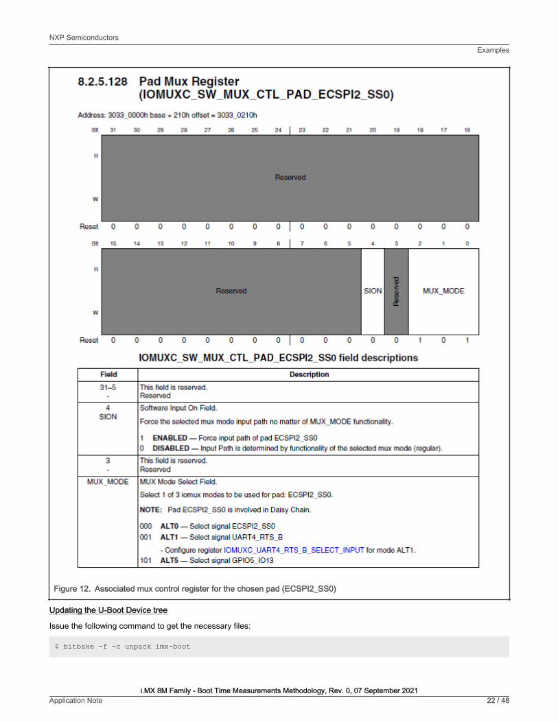
Figure 12. Associated mux control register for the chosen pad (ECSPI2_SS0)
Updating the U-Boot Device tree
Issue the following command to get the necessary files:
$ bitbake -f -c unpack imx-boot
NXP SemiconductorsExamples
i.MX 8M Family - Boot Time Measurements Methodology, Rev. 0, 07 September 2021Application Note 22 / 48

To update the device tree, find out the macro associated to the desired functionality. This information isin the <yocto_build_dir>/tmp/work/imx8mmevk-poky-linux/u-boot-imx/<specified_git_folder>/git/arch/arm/dts/imx8mm-pinfunc.h file. However, the use of this macro is not enough for an adequate pin mux setup, because it requires a sixthvalue, which represents the pad configuration.
#define MX8MM_IOMUXC_ECSPI2_SS0_ECSPI2_SS0 0x210 0x478 0x000 0x0 0x0#define MX8MM_IOMUXC_ECSPI2_SS0_UART4_DCE_RTS_B 0x210 0x478 0x508 0x1 0x1#define MX8MM_IOMUXC_ECSPI2_SS0_UART4_DTE_CTS_B 0x210 0x478 0x000 0x1 0x0#define MX8MM_IOMUXC_ECSPI2_SS0_GPIO5_IO13 0x210 0x478 0x000 0x5 0x0#define MX8MM_IOMUXC_ECSPI2_SS0_TPSMP_HDATA15 0x210 0x478 0x000 0x7 0x0
The associated DTS file for the i.MX 8MM EVK board (<yocto_build_dir>/tmp/work/imx8mmevk-poky-linux/u-boot-imx/<specified_git_folder>/git/arch/arm/dts/imx8mm-evk.dts) shows that the pin is not used, so there is nothing to disable.
To use the pin with the GPIO functionality, add the following pin muxing into iomuxc.
pinctrl_hog_1: hoggrp-1 {fsl,pins = <MX8MM_IOMUXC_ECSPI2_SS0_GPIO5_IO13 0x16>;};
The 0x16 configuration is based on the following pad settings in the IOMUXC_SW_PAD_CTL_PAD_ECSPI2_SS0 register:
• Drive Strength Field: X6
• Slew Rate Field: Fast
• Open Drain Enable field: Disabled
• Control IO ports PS: Pull-down resistors
• Hysteresis Enable Field: CMOS
• Pull Resistors Enable Field: Pull Disabled
Updating the Linux device tree
To update the device tree, find out the macro associated to the desired functionality. This information is in the<yocto_build_dir>/tmp/work-shared/imx8mmevk/kernel_source/arch/arm64/boot/dts/freescale/imx8mm-pinfunc.hfile. However, the use of this macro is not enough for an adequate pin mux setup, because it requires a sixth value, whichrepresents the pad configuration.
#define MX8MM_IOMUXC_ECSPI2_SS0_ECSPI2_SS0 0x210 0x478 0x000 0x0 0x0#define MX8MM_IOMUXC_ECSPI2_SS0_UART4_DCE_RTS_B 0x210 0x478 0x508 0x1 0x1#define MX8MM_IOMUXC_ECSPI2_SS0_UART4_DTE_CTS_B 0x210 0x478 0x000 0x1 0x0#define MX8MM_IOMUXC_ECSPI2_SS0_GPIO5_IO13 0x210 0x478 0x000 0x5 0x0#define MX8MM_IOMUXC_ECSPI2_SS0_TPSMP_HDATA15 0x210 0x478 0x000 0x7 0x0
The associated DTS file for the i.MX 8MM EVK (<yocto_build_dir>/tmp/work-shared/imx8mmevk/kernel_source/arch/arm64/boot/dts/freescale/imx8mm-evk.dts) shows that the pin is not used, so there is nothing to disable.
To use the pin with the GPIO functionality, add the following pin muxing into iomuxc. If the chosen pad has another pin muxconfiguration, replace the respective pin muxing with the following to successfully generate the pulse in Linux:
pinctrl_hog: hoggrp {fsl,pins = <MX8MM_IOMUXC_ECSPI2_SS0_GPIO5_IO13 0x16>;};
NXP SemiconductorsExamples
i.MX 8M Family - Boot Time Measurements Methodology, Rev. 0, 07 September 2021Application Note 23 / 48

Add the first pulse generator into <yocto_build_dir>/tmp/work/imx8mmevk-poky-linux/u-boot-imx/<specified_git_folder>/git /board/freescale/imx8mm_evk/spl.c.
Firstly, declare a macro containing the pair of GPIO group and GPIO pin in the file:
#define TIMED_GPIO IMX_GPIO_NR(5, 13)
Secondly, there must be a macro to use a pad as a GPIO. In this case, the macro already exists:
#define USDHC_GPIO_PAD_CTRL (PAD_CTL_HYS | PAD_CTL_DSE1)
Add the pulse generation code into the board_init_f function, after the BSS clearing part.
void board_init_f(ulong dummy) { int ret; /* Clear the BSS. */ memset(__bss_start, 0, __bss_end - __bss_start); gpio_request(TIMED_GPIO, "timed_gpio"); gpio_direction_output(TIMED_GPIO, 1); gpio_direction_output(TIMED_GPIO, 0); arch_cpu_init();
Adding the second pulse generator in <yocto_build_dir>/tmp/work/imx8mmevk-poky-linux/u-boot-imx/<specified_git_folder>/git/include/configs/imx8mm_evk.h
The commands to toggle the pin are added in the environment variables for the bootloader, at the load image property. Set thepin before loading the image and reset it afterwards:
“loadimage=gpio set GPIO5_13;fatload mmc ${mmcdev}:${mmcpart} ${loadaddr} ${image};gpio clearGPIO5_13\0” \
To automate the process, create a patch, which contains the U-Boot modifications in the spl.c, imx8mm-evk.dts, andimx8mm_evk.h files. Add the details after the last commands describing the nature of the patch:
$ git add board/freescale/imx8mm_evk/spl.c$ git add arch/arm/dts/imx8mm-evk.dts$ git add include/configs/imx8mm_evk.h$ git commit -s$ git format-patch HEAD~1
Copy the resulting patch to the following location: <yocto_dir>/imx-yocto-bsp/sources/meta-imx/meta-bsp/recipes-bsp/u-boot/u-boot-imx. Add the name of the patch into the source location identifier in the Yocto recipe for U-Boot (<yocto_dir>/imx-yocto-bsp/sources/meta-imx/meta-bsp/recipes-bsp/u-boot/u-boot-imx_2020.04.bb):
SRC_URI = " ...\file://<patch_name>.patch \ "
Apply the following commands to check that the patch works after the modifications, after which the files should contain thefollowing changes:
$ bitbake -f -c clean u-boot-imx$ bitbake u-boot-imx$ bitbake imx-boot
Adding the third pulse generator
NXP SemiconductorsExamples
i.MX 8M Family - Boot Time Measurements Methodology, Rev. 0, 07 September 2021Application Note 24 / 48

For this stage, modify the Yocto recipe extension for psplash so that it can fetch the additional libgpiod library necessary totoggle the GPIO (<yocto_dir>/sources/meta-imx/meta-bsp/recipes-core/psplash/psplash_git.bbappend):
DEPENDS = "libgpiod" RDEPENDS_${PN} = "libgpiod" RDEPENDS_${PN}-dev = "libgpiod"
Issue the following command to get the necessary psplash files:
$ bitbake -f -c unpack psplash
After fetching the necessary files, modify the makefile (<yocto_build_dir>/tmp/work/aarch64-poky-linux/psplash/<specified_git_folder>/git/Makefile.am) to include the lgpiod:
AM_CFLAGS = $(GCC_FLAGS) -D_GNU_SOURCE -lgpiod GCC_FLAGS := $(GCC_FLAGS) -Lusr/lib -Iusr/include -lgpiod LD_FLAGS = $(LD_FLAGS) -lgpiod
Modify the source code (<yocto_build_dir>/tmp/work/aarch64-poky-linux/psplash/<specified_git_folder>/git/psplash.c). The first step is to include the library:
#include "gpiod.h"
Declare some additional variables in the main function, responsible for selecting the bank and the line for the GPIO. The banksare zero-indexed, so the number of the GPIO bank must be decremented by one:
struct gpiod_chip *chip;struct gpiod_line *line;int gpio_line = 13;char dev[] = "/dev/gpiochip4";
Before sending the first command to the frame buffer (clearing the background), the program should acquire control of the pin,toggle it, and release it.
chip = gpiod_chip_open(dev); if (!chip) return -1; line = gpiod_chip_get_line(chip, gpio_line); if (!line) { gpiod_chip_close(chip); return -1; } req = gpiod_line_request_output(line, "SIGNAL", 2); if (req) { gpiod_chip_close(chip); return -1; } if (gpiod_line_set_value(line, 1) != 0){ printf("Impossible to change line %d value to %d \n", gpio_line, 1); gpiod_chip_close(chip); return -1; } if (gpiod_line_set_value(line, 0) != 0){ printf("Impossible to change line %d value to %d \n", gpio_line, 0); gpiod_chip_close(chip); return -1; } gpiod_line_release(line); gpiod_chip_close(chip);
After applying all the modifications, build the psplash and the image using the following commands:
$ bitbake psplash$ bitbake imx-image-core
To automate this process, create a patch that contains the modifications in the Makefile.am and psplash.c files. Add the detailsafter the last commands describing the nature of the patch:
$ git add Makefile.am$ git add psplash.c
NXP SemiconductorsExamples
i.MX 8M Family - Boot Time Measurements Methodology, Rev. 0, 07 September 2021Application Note 25 / 48

$ git commit -s$ git format-patch HEAD~1
The resulting patch is then copied to the following location: <yocto_dir>/imx-yocto-bsp/sources/meta-imx/meta-bsp/recipes-core/psplash/files. The name of the patch is then added into the source location identifier in the Yocto Recipeextension for psplash (<yocto_dir>/sources/meta-imx/meta-bsp/recipes-core/psplash/psplash_git.bbappend).
SRC_URI += " \ file://psplash-start.service \ file://psplash-basic.service \ file://psplash-network.service \ file://psplash-quit.service \ file://<patch_name>.patch \ "
Apply the following commands to check that the patch works after the modifications, after which the psplash.c and Makefile.amshould contain the following changes:
$ bitbake -f -c clean psplash$ bitbake psplash$ bitbake imx-image-core
Measuring the total time with the logic analyzer
This part starts by setting up all the preliminary connections, such as the power supply, debug port, download port, and MIPI-DSIto HDMI connections. If the HDMI display is not connected and functional, the psplash pulse generation does not work, becausethere are no frame buffers.
Both the bootloader and the Linux image must be built using bitbake. After that, write them to the board using the UUU program,in which you can choose between writing to the on-board eMMC or the SD card.
The measuring stand is set up by connecting the logic analyzer to the board. The nRST signal is used as a starting reference,which can be found on the JTAG connector at pin 10.
NXP SemiconductorsExamples
i.MX 8M Family - Boot Time Measurements Methodology, Rev. 0, 07 September 2021Application Note 26 / 48

Figure 13. Schematic view of the JTAG connector available on the i.MX 8MM EVK board
To capture the rising edges of the chosen pin, connect the second probe of the analyzer to the 24th pin on the J1003expansion connector.
NXP SemiconductorsExamples
i.MX 8M Family - Boot Time Measurements Methodology, Rev. 0, 07 September 2021Application Note 27 / 48

Figure 14. Measurement setup on the i.MX 8MM EVK board
After checking that both probes are referenced to the board’s ground, start the logic analyzer software, where you can set up theprobe parameters and the time frame.
Configure the board to start in the internal development mode, boot from the desired storage space, and then power it on. Afterthe psplash screen disappears, press the reset button on the board and start the recording on the logic analyzer software.
You should see a rising edge on the nRST pin, followed by three pulses on the chosen pin. Stop the recording and place themeasurement flags to find out the time for each phase. The boot time of the board in this configuration results from the sum of theelapsed time for each stage.
NXP SemiconductorsExamples
i.MX 8M Family - Boot Time Measurements Methodology, Rev. 0, 07 September 2021Application Note 28 / 48

Figure 15. Measurement setup on the i.MX 8MM EVK board
3.4 i.MX 8M NanoChoosing the pins
The chosen pin is the 24th pin on the J1003 expansion connector on the specified board. In the schematics for the baseboard, thepin is used for the ECSPI 2 peripheral with the ECSPI2_SS0 function. Searching the specified signal in the reference manual forthe associated pin returns an alternate function of GPIO5_IO[13].
Figure 16. Schematic view of the expansion connector for the i.MX 8MN EVK board
NXP SemiconductorsExamples
i.MX 8M Family - Boot Time Measurements Methodology, Rev. 0, 07 September 2021Application Note 29 / 48

Figure 17. Associated mux control register for the chosen pad (ECSPI2_SS0)
Updating the U-Boot device tree
Issue the following command to get the necessary files:
$ bitbake -f -c unpack imx-boot
NXP SemiconductorsExamples
i.MX 8M Family - Boot Time Measurements Methodology, Rev. 0, 07 September 2021Application Note 30 / 48

To update the device tree, find out the macro associated to the desired functionality. This information isin the <yocto_build_dir>/tmp/work/imx8mnevk-poky-linux/u-boot-imx/<specified_git_folder>/git/arch/arm/dts/imx8mn-pinfunc.h file. The use of this macro is not enough for an adequate pin mux setup, because it requires a sixth value,which represents the pad configuration.
#define MX8MN_IOMUXC_ECSPI2_SS0_ECSPI2_SS0 0x0210 0x0478 0x0570 0x0 0x0#define MX8MN_IOMUXC_ECSPI2_SS0_UART4_DCE_RTS_B 0x0210 0x0478 0x0508 0x1 0x1#define MX8MN_IOMUXC_ECSPI2_SS0_UART4_DTE_CTS_B 0x0210 0x0478 0x0000 0x1 0x0#define MX8MN_IOMUXC_ECSPI2_SS0_I2C4_SDA 0x0210 0x0478 0x058C 0x2 0x5#define MX8MN_IOMUXC_ECSPI2_SS0_GPIO5_IO13 0x0210 0x0478 0x0000 0x5 0x0
The associated DTS file for the i.MX 8MN EVK board (<yocto_build_dir>/tmp/work/imx8mnevk-poky-linux/u-boot-imx/<specified_git_folder>/git/arch/arm/dts/imx8mn-evk.dts) shows that the pin is not used, so there is nothing to disable.
To use the pin with the GPIO functionality, add the following pin muxing into iomuxc:
pinctrl_hog_1: hoggrp-1 {fsl,pins = <MX8MN_IOMUXC_ECSPI2_SS0_GPIO5_IO13 0x16>;};
The 0x16 configuration is based on the following pad settings in the IOMUXC_SW_PAD_CTL_PAD_ECSPI2_SS0 register:
• Drive Strength Field: X6
• Slew Rate Field: Fast
• Open Drain Enable field: Disabled
• Control IO ports PS: Pull-down resistors
• Hysteresis Enable Field: CMOS
• Pull Resistors Enable Field: Pull Disabled
Updating the Linux device tree
To update the device tree, find out the macro associated to the desired functionality. This information is in the<yocto_build_dir>/tmp/work-shared/imx8mnevk/kernel_source/arch/arm64/boot/dts/freescale/imx8mn-pinfunc.hfile. The use of this macro is not enough for an adequate pin mux setup, because it requires a sixth value, which represents thepad configuration.
#define MX8MN_IOMUXC_ECSPI2_SS0_ECSPI2_SS0 0x210 0x478 0x570 0x0 0x0#define MX8MN_IOMUXC_ECSPI2_SS0_UART4_DCE_RTS_B 0x210 0x478 0x508 0x1 0x1#define MX8MN_IOMUXC_ECSPI2_SS0_UART4_DTE_CTS_B 0x210 0x478 0x000 0x1 0x0#define MX8MN_IOMUXC_ECSPI2_SS0_I2C4_SDA 0x210 0x478 0x58C 0x2 0x5#define MX8MN_IOMUXC_ECSPI2_SS0_GPIO5_IO13 0x210 0x478 0x000 0x5 0x0
The associated DTS file for the i.MX 8MN EVK (<yocto_build_dir>/tmp/work-shared/imx8mnevk/kernel_source/arch/arm64/boot/dts/freescale/imx8mn-evk.dts) shows that the pin is not used, so there is nothing to disable.
To use the pin with the GPIO functionality, add the following pin muxing into iomuxc. If the chosen pad has another pin muxconfiguration, the respective pin muxing must be replaced with the following to successfully generate the pulse in Linux:
pinctrl_hog: hoggrp {fsl,pins = <MX8MN_IOMUXC_ECSPI2_SS0_GPIO5_IO13 0x16>;};
NXP SemiconductorsExamples
i.MX 8M Family - Boot Time Measurements Methodology, Rev. 0, 07 September 2021Application Note 31 / 48

Adding the first pulse generator in <yocto_build_dir>/tmp/work/imx8mnevk-poky-linux/u-boot-imx/<specified_git_folder>/git/board/freescale/imx8mn_evk/spl.c
Firstly, declare a macro containing the pair of GPIO group and GPIO pin in the file:
#define TIMED_GPIO IMX_GPIO_NR(5, 13)
There must be a macro for using a pad as a GPIO. In this case, it already exists.
#define USDHC_GPIO_PAD_CTRL (PAD_CTL_HYS | PAD_CTL_DSE1)
Add the pulse generation code into the board_init_f function, after the BSS clearing part:
void board_init_f(ulong dummy) { int ret; /* Clear the BSS. */ memset(__bss_start, 0, __bss_end - __bss_start); gpio_request(TIMED_GPIO, "timed_gpio"); gpio_direction_output(TIMED_GPIO, 1); gpio_direction_output(TIMED_GPIO, 0); arch_cpu_init();
Adding the second pulse generator in <yocto_build_dir>/tmp/work/imx8mnevk-poky-linux/u-boot-imx/<specified_git_folder>/git/include/configs/imx8mn_evk.h
Add the commands to toggle the pin into the environment variables for the bootloader, at the load image property. Set the pinbefore loading the image and reset it afterwards:
“loadimage=gpio set GPIO5_13;fatload mmc ${mmcdev}:${mmcpart} ${loadaddr} ${image};gpio clear GPIO5_13\0” \
To automate the process, create a patch that contains the U-Boot modifications in the spl.c , imx8mn-evk.dts andimx8mn_evk.h files. Add the details after the last commands, describing the nature of the patch:
$ git add board/freescale/imx8mn_evk/spl.c$ git add arch/arm/dts/imx8mn-evk.dts$ git add include/configs/imx8mn_evk.h$ git commit -s$ git format-patch HEAD~1
Copy the resulting patch to the following location: <yocto_dir>/imx-yocto-bsp/sources/meta-imx/meta-bsp/recipes-bsp/u-boot/u-boot-imx. Add the name of the patch into the source location identifier in the Yocto recipe for U-Boot (<yocto_dir>/imx-yocto-bsp/sources/meta-imx/meta-bsp/recipes-bsp/u-boot/u-boot-imx_2020.04.bb):
SRC_URI = " ...\file://<patch_name>.patch \ "
To check that the patch works after the modifications, apply the following commands, after which the files should contain thefollowing changes:
$ bitbake -f -c clean u-boot-imx$ bitbake u-boot-imx$ bitbake imx-boot
Adding the third pulse generator
NXP SemiconductorsExamples
i.MX 8M Family - Boot Time Measurements Methodology, Rev. 0, 07 September 2021Application Note 32 / 48

For this stage, modify the Yocto recipe extension for psplash so that it can fetch the additional libgpiod library to toggle the GPIO(<yocto_dir>/sources/meta-imx/meta-bsp/recipes-core/psplash/psplash_git.bbappend):
DEPENDS = "libgpiod" RDEPENDS_${PN} = "libgpiod" RDEPENDS_${PN}-dev = "libgpiod"
Issue the following command to get the necessary psplash files:
$ bitbake -f -c unpack psplash
After fetching the necessary files, modify the makefile (<yocto_build_dir>/tmp/work/aarch64-poky-linux/psplash/<specified_git_folder>/git/Makefile.am) to include the lgpiod:
AM_CFLAGS = $(GCC_FLAGS) -D_GNU_SOURCE -lgpiod GCC_FLAGS := $(GCC_FLAGS) -Lusr/lib -Iusr/include -lgpiod LD_FLAGS = $(LD_FLAGS) -lgpiod
Modify the source code (<yocto_build_dir>/tmp/work/aarch64-poky-linux/psplash/<specified_git_folder>/git/psplash.c). The first step is to include the library:
#include "gpiod.h"
Declare some additional variables in the main function to select the bank and the line for the GPIO. The banks are zero-indexed,so the number of the GPIO bank must be decremented by one.
struct gpiod_chip *chip;struct gpiod_line *line;int gpio_line = 13;char dev[] = "/dev/gpiochip4";
The program should acquire control of the pin, toggle it, and release it before sending the first command to the frame buffer(clearing the background):
chip = gpiod_chip_open(dev); if (!chip) return -1; line = gpiod_chip_get_line(chip, gpio_line); if (!line) { gpiod_chip_close(chip); return -1; } req = gpiod_line_request_output(line, "SIGNAL", 2); if (req) { gpiod_chip_close(chip); return -1; } if (gpiod_line_set_value(line, 1) != 0){ printf("Impossible to change line %d value to %d \n", gpio_line, 1); gpiod_chip_close(chip); return -1; } if (gpiod_line_set_value(line, 0) != 0){ printf("Impossible to change line %d value to %d \n", gpio_line, 0); gpiod_chip_close(chip); return -1; } gpiod_line_release(line); gpiod_chip_close(chip);
After applying all the modifications, build the psplash and the image using the following commands:
$ bitbake psplash$ bitbake imx-image-core
To automate this process, create a patch that contains the modifications in the Makefile.am and psplash.c files. Add the detailsafter the last commands, describing the nature of the patch:
$ git add Makefile.am$ git add psplash.c
NXP SemiconductorsExamples
i.MX 8M Family - Boot Time Measurements Methodology, Rev. 0, 07 September 2021Application Note 33 / 48

$ git commit -s$ git format-patch HEAD~1
The resulting patch is then copied to the following location: <yocto_dir>/imx-yocto-bsp/sources/meta-imx/meta-bsp/recipes-core/psplash/files. The name of the patch is then added in the source location identifier in the Yocto Recipeextension for psplash (<yocto_dir>/sources/meta-imx/meta-bsp/recipes-core/psplash/psplash_git.bbappend).
SRC_URI += " \ file://psplash-start.service \ file://psplash-basic.service \ file://psplash-network.service \ file://psplash-quit.service \ file://<patch_name>.patch \ "
To check that the patch works after the modifications, apply the following commands, after which the psplash.c and Makefile.amshould contain the following changes:
$ bitbake -f -c clean psplash$ bitbake psplash$ bitbake imx-image-core
Measuring the total time with the logic analyzer
This part starts by setting up all the preliminary connections, such as the power supply, debug port, download port, and MIPI-DSIto HDMI connections. If the HDMI display is not connected and functional, the psplash pulse generation does not work, becausethere are no frame buffers.
Both the bootloader and Linux image must be built using bitbake. After that, write them to the board using the UUU program, inwhich you can choose between writing to the on-board eMMC or the SD card.
Set up the measuring stand by connecting the logic analyzer to the board. The nRST signal is used as a starting reference andit is on the JTAG connector at pin 10.
NXP SemiconductorsExamples
i.MX 8M Family - Boot Time Measurements Methodology, Rev. 0, 07 September 2021Application Note 34 / 48

Figure 18. Schematic view of the JTAG connector available on the i.MX 8MN EVK board
To capture the rising edges of the chosen pin, connect the second probe of the analyzer to the 24th pin on the J1003expansion connector.
NXP SemiconductorsExamples
i.MX 8M Family - Boot Time Measurements Methodology, Rev. 0, 07 September 2021Application Note 35 / 48

Figure 19. Measurement setup on the i.MX 8MN EVK board
After checking that both probes are referenced to the board’s ground, start the logic analyzer software, where you can set theprobe parameters and the time frame.
Configure the board to start in the internal development mode, boot from the desired storage space, and then power it on. Afterthe psplash screen disappears, press the reset button on the board and start the recording on the logic analyzer software.
You should see a rising edge on the nRST pin, followed by three pulses on the chosen pin. Stop the recording and place themeasurement flags to find out the time for each phase. The boot time of the board in this configuration results from the sum of theelapsed time for each stage.
NXP SemiconductorsExamples
i.MX 8M Family - Boot Time Measurements Methodology, Rev. 0, 07 September 2021Application Note 36 / 48

Figure 20. Measurements on the boot time for i.MX 8MN EVK board
4 Further optimizations
4.1 No delay in kernel loadingBefore the U-Boot Kernel image loads according to the autoboot sequence, there is a delay during which you can stop the process.This delay is defined in the u-boot environment variables as bootdelay and it may vary between the boards.
To achieve shorter boot times, configure the bootdelay to 0 after interrupting the autoboot sequence during the delay:
u-boot=> setenv bootdelay 0u-boot=> saveenvSaving Environment to MMC... Writing to MMC(1)... OK
After measuring the boot times, the total time shall decrease by the default bootdelay period.
4.2 Quiet operationDuring the Linux start-up sequence, different messages are sent through the debug port, which has a limited speed (serialconsole). To achieve shorter boot times, suppress some of these messages using the quiet parameter in the mmcargsenvironment variable.
u-boot=> edit mmcargsedit: setenv bootargs ${jh_clk} console=${console} root=${mmcroot} quiet u-boot=> saveenvSaving Environment to MMC... Writing to MMC(1)... OK
NXP SemiconductorsFurther optimizations
i.MX 8M Family - Boot Time Measurements Methodology, Rev. 0, 07 September 2021Application Note 37 / 48

4.3 Enabling fast boot and using higher speeds for the storageFor the SD and eMMC storage, you can set higher speeds in the ROM stage of booting, depending on the available configuration.For eMMC, you can activate the fast boot mode. You can set these modifications using the boot fuses. In some cases, there isalso the option to bypass the fuses using a predefined GPIO.
The following examples are applicable for the eMMC storage, because no notable decreases in boot time have been observedfor the SD.
Case I : Changes can be applied externally by GPIO pins
The prerequisite for this mode is that the BT_FUSE_SEL fuse must be intact (0), so that the GPIO boot overrides can work. The boardmust also boot from the MicroSD card.
• i.MX 8M Quad
The GPIO pins that override the fuses are in the i.MX 8MQ reference manual.
Figure 21. GPIO overrides for the i.MX 8MQ EVK board
In the board configuration, the onboard eMMC supports the DDR mode, which can lead to shorter boot times. You can set theMMC speed to high and enable the fast boot mode.
NXP SemiconductorsFurther optimizations
i.MX 8M Family - Boot Time Measurements Methodology, Rev. 0, 07 September 2021Application Note 38 / 48
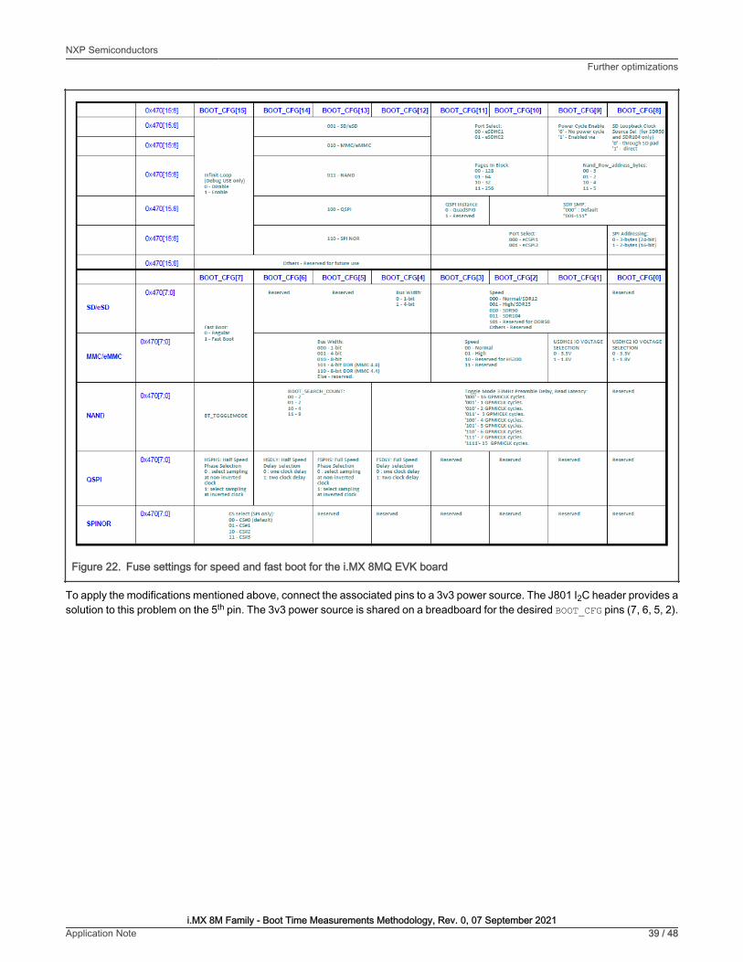
Figure 22. Fuse settings for speed and fast boot for the i.MX 8MQ EVK board
To apply the modifications mentioned above, connect the associated pins to a 3v3 power source. The J801 I2C header provides asolution to this problem on the 5th pin. The 3v3 power source is shared on a breadboard for the desired BOOT_CFG pins (7, 6, 5, 2).
NXP SemiconductorsFurther optimizations
i.MX 8M Family - Boot Time Measurements Methodology, Rev. 0, 07 September 2021Application Note 39 / 48

Figure 23. I2C header schematic for the i.MX 8MQ EVK board
NXP SemiconductorsFurther optimizations
i.MX 8M Family - Boot Time Measurements Methodology, Rev. 0, 07 September 2021Application Note 40 / 48

Figure 24. Board setup with breadboard for the i.MX 8MQ EVK board
Before you apply any of the following commands, identify the eMMC device in both U-Boot and Linux, because theassociated id/name is used in the next steps. The storage mapping for the evaluation board is as follows: eSDHC1for the eMMC card and eSDHC2 for the MicroSD.
NOTE
To use fast boot, rebuild the u-boot image using the flash_evk_emmc_fastboot target. You can do this by adding the followinglines to the local.conf file in the <yocto_build_dir>/conf directory:
IMXBOOT_TARGETS_append = " flash_evk_emmc_fastboot"
NXP SemiconductorsFurther optimizations
i.MX 8M Family - Boot Time Measurements Methodology, Rev. 0, 07 September 2021Application Note 41 / 48
After this, rebuild the image using the following bitbake commands:
$ bitbake -f -c clean imx-boot$ bitbake imx-boot
An additional image that contains the flash_evk_emmc_fastboot settings should be available in the <yocto_build_dir>/tmp/deploy/images/imx8mqevk/ directory.
The majority of the MMC settings can be modified in the U-Boot using the mmc bootbus command, which sets theBOOT_BUS_WIDTH field:
u-boot=> mmc bootbus <device_number> 2 1 2
Write the Image Vector Table (IVT) to a different offset, as per the reference manual (from 33 kB to 1 kB). You can do thisin Linux by enabling the write rights to the bootpartition, writing the new U-Boot image, disabling the rights, and setting it asthe bootpartition.
root@imx8mqevk:~# echo 0 > /sys/block/mmcblk<device_number>boot<partition_number>/force_roroot@imx8mqek:~# dd if=<location to flash.bin>/flash.bin of=/dev/mmcblk<device_number>boot<partition_number> seek=1 bs=1k conv=fsyncroot@imx8mqek:~# echo 1 > /sys/block/mmcblk<device_number>boot<partition_number>/force_roroot@imx8mqevk:~# mmc bootpart enable 1 0 /dev/mmcblk<device_number>root@imx8mqevk:~# sync
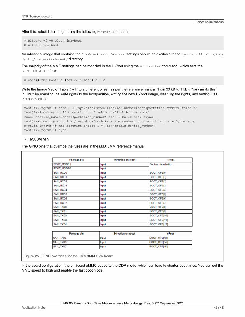
• i.MX 8M Mini
The GPIO pins that override the fuses are in the i.MX 8MM reference manual.
Figure 25. GPIO overrides for the i.MX 8MM EVK board
In the board configuration, the on-board eMMC supports the DDR mode, which can lead to shorter boot times. You can set theMMC speed to high and enable the fast boot mode.
NXP SemiconductorsFurther optimizations
i.MX 8M Family - Boot Time Measurements Methodology, Rev. 0, 07 September 2021Application Note 42 / 48

Figure 26. Fuse settings for speed and fast boot for the i.MX 8MM EVK board
To apply the modifications mentioned above, connect the associated pins to a 3v3 power source. The evaluation board has twosets of ten switches through which the pins can be set or reset: SW1101 and SW1102.
NXP SemiconductorsFurther optimizations
i.MX 8M Family - Boot Time Measurements Methodology, Rev. 0, 07 September 2021Application Note 43 / 48

Figure 27. Schematic view of the GPIO override switches on the i.MX 8MM EVK board
NXP SemiconductorsFurther optimizations
i.MX 8M Family - Boot Time Measurements Methodology, Rev. 0, 07 September 2021Application Note 44 / 48

Before you apply any of the following commands, identify the eMMC device in both U-Boot and Linux, becausethe associated id/name is used in the next steps. The storage mapping for the development board is as follows:eSDHC2 for the MicroSD card and eSDHC3 for the eMMC.
NOTE
To use the fast boot, rebuild the U-Boot image using the flash_evk_emmc_fastboot target. You can do this by adding thefollowing lines to the local.conf file in the <yocto_build_dir>/conf directory:
IMXBOOT_TARGETS_append = " flash_evk_emmc_fastboot"
After this, rebuild the image using the following bitbake commands:
$ bitbake -f -c clean imx-boot$ bitbake imx-boot
An additional image that contains the flash_evk_emmc_fastboot settings should be available in the <yocto_build_dir>/tmp/deploy/images/imx8mmevk/ directory.
You can modify the majority of the MMC settings in the U-Boot using the mmc bootbus command, which sets theBOOT_BUS_WIDTH field:
u-boot=> mmc bootbus <device_number> 2 1 2
Write the Image Vector Table (IVT) to a different offset, as per the reference manual (from 33 kB to 1 kB). You can do thisin Linux by enabling the write rights to the bootpartition, writing the new U-Boot image, disabling the rights, and setting it asthe bootpartition.
root@imx8mmevk:~# echo 0 > /sys/block/mmcblk<device_number>boot<partition_number>/force_roroot@imx8mmek:~# dd if=<location to flash.bin>/flash.bin of=/dev/mmcblk<device_number>boot<partition_number> seek=1 bs=1k conv=fsyncroot@imx8mmek:~# echo 1 > /sys/block/mmcblk<device_number>boot<partition_number>/force_roroot@imx8mmevk:~# mmc bootpart enable 1 0 /dev/mmcblk<device_number>root@imx8mmevk:~# sync
Case II : Changes can be applied by writing the boot fuses
• i.MX 8M Plus
In the board configuration, the onboard eMMC supports the DDR mode, which can lead to shorter boot times. You can set theMMC speed to high and the fast boot mode can be enabled.
Figure 28. Fuse settings for speed and fast boot for the i.MX 8MP EVK board
Before you apply any of the following commands, identify the eMMC device in both U-Boot and Linux, because theassociated id/name is used in the next steps. The storage mapping for the evaluation board is as follows: eSDHC2for the MicroSD card and eSDHC3 for the eMMC.
NOTE
You can modify the majority of the MMC settings in the U-Boot using the mmc bootbus command, which sets theBOOT_BUS_WIDTH field:
u-boot=> mmc bootbus <device number> 2 1 2
NXP SemiconductorsFurther optimizations
i.MX 8M Family - Boot Time Measurements Methodology, Rev. 0, 07 September 2021Application Note 45 / 48

To apply the modifications mentioned above at the chip level, you must blow the fuses. This process is irreversible,so double check the values before writing the fuses according to the reference manual.
NOTE
The fuses are written in the u-boot using the fuse prog command. This requires the bank and word in which the fuse resides,followed by a word containing the settings for the fuses. Find out the bank and word as follows:
(0x490-0x400)/0x10= 0x9 Hexadecimal = 9 Decimal
9/4 = 2 and the remainder is 1 (Bank = 2 and Word = 1)
The fuses that you must blow are as follows:
• 0x490[6] – Fast Boot
• 0x490[5] – 8-bit DDR
• 0x490[2] – EMMC Speed High
The resulting word to write for the desired configuration is 0x64:
u-boot=> fuse prog 2 1 0x64
To use the fast boot, there is no additional modification to the U-Boot image, because there is no different offset for the ImageVector Table (IVT).
• i.MX 8M Nano
The board configuration shows that the on-board eMMC supports the DDR mode, which can lead to shorter boot times. You canset the MMC speed to high and enable the fast boot mode.
Figure 29. Fuse settings for speed and fast boot for the i.MX 8MN EVK board
Before applying any of the following commands, you must identify the eMMC device in both U-Boot and Linux,because the associated id/name is used in the next steps. The storage mapping for the evaluation board is asfollows: eSDHC2 for the MicroSD card and eSDHC3 for the eMMC.
NOTE
You can modify the majority of the MMC settings in the U-Boot using the mmc bootbus command, which sets theBOOT_BUS_WIDTH field:
u-boot=> mmc bootbus <device number> 2 1 2
To apply the modifications mentioned above at the chip level, you must blow the fuses. This process is irreversible,so double check the values before writing the fuses according to the reference manual.
NOTE
NXP SemiconductorsFurther optimizations
i.MX 8M Family - Boot Time Measurements Methodology, Rev. 0, 07 September 2021Application Note 46 / 48

The fuses are written in the U-Boot using the fuse prog command, which requires the bank and word in which the fuse resides,followed by a word containing the settings for the fuses. Find out the bank and word as follows:
(0x490-0x400)/0x10= 0x9 Hexadecimal = 9 Decimal
9/4 = 2 and the remainder is 1 (Bank = 2 and Word = 1)
The fuses that you must blow are as follows:
• 0x490[6] – Fast Boot
• 0x490[5] – 8-bit DDR
• 0x490[2] – EMMC Speed High
The resulting word to write for the desired configuration is 0x64:
u-boot=> fuse prog 2 1 0x64
To use the fast boot, there is no additional modification to the U-Boot image, because there is no different offset for the ImageVector Table (IVT).
5 References• i.MX 8M Quad Applications Processor Reference Manual (document )
• i.MX 8M Plus Applications Processor Reference Manual (document )
• i.MX 8M Mini Applications Processor Reference Manual (document )
• i.MX 8M Nano Applications Processor Reference Manual (document )
6 Revision historyTable 1. Revision history
Revision number Date Substantive changes
0 07 September 2021 Initial release
NXP SemiconductorsReferences
i.MX 8M Family - Boot Time Measurements Methodology, Rev. 0, 07 September 2021Application Note 47 / 48

How To ReachUs
Home Page:
nxp.com
Web Support:
nxp.com/support
Limited warranty and liability — Information in this document is provided solely to enable system and software implementers to use NXPproducts. There are no express or implied copyright licenses granted hereunder to design or fabricate any integrated circuits based onthe information in this document. NXP reserves the right to make changes without further notice to any products herein.
NXP makes no warranty, representation, or guarantee regarding the suitability of its products for any particular purpose, nor doesNXP assume any liability arising out of the application or use of any product or circuit, and specifically disclaims any and all liability,including without limitation consequential or incidental damages. “Typical” parameters that may be provided in NXP data sheets and/orspecifications can and do vary in different applications, and actual performance may vary over time. All operating parameters, including“typicals,” must be validated for each customer application by customer's technical experts. NXP does not convey any license under itspatent rights nor the rights of others. NXP sells products pursuant to standard terms and conditions of sale, which can be found at thefollowing address: nxp.com/SalesTermsandConditions.
Right to make changes - NXP Semiconductors reserves the right to make changes to information published in this document, includingwithout limitation specifications and product descriptions, at any time and without notice. This document supersedes and replaces allinformation supplied prior to the publication hereof.
Security — Customer understands that all NXP products may be subject to unidentified or documented vulnerabilities. Customeris responsible for the design and operation of its applications and products throughout their lifecycles to reduce the effect of thesevulnerabilities on customer’s applications and products. Customer’s responsibility also extends to other open and/or proprietarytechnologies supported by NXP products for use in customer’s applications. NXP accepts no liability for any vulnerability. Customershould regularly check security updates from NXP and follow up appropriately. Customer shall select products with security features thatbest meet rules, regulations, and standards of the intended application and make the ultimate design decisions regarding its productsand is solely responsible for compliance with all legal, regulatory, and security related requirements concerning its products, regardlessof any information or support that may be provided by NXP. NXP has a Product Security Incident Response Team (PSIRT) (reachableat [email protected]) that manages the investigation, reporting, and solution release to security vulnerabilities of NXP products.
NXP, the NXP logo, NXP SECURE CONNECTIONS FOR A SMARTER WORLD, COOLFLUX,EMBRACE, GREENCHIP, HITAG,ICODE, JCOP, LIFE, VIBES, MIFARE, MIFARE CLASSIC, MIFARE DESFire, MIFARE PLUS, MIFARE FLEX, MANTIS, MIFAREULTRALIGHT, MIFARE4MOBILE, MIGLO, NTAG, ROADLINK, SMARTLX, SMARTMX, STARPLUG, TOPFET, TRENCHMOS,UCODE, Freescale, the Freescale logo, AltiVec, CodeWarrior, ColdFire, ColdFire+, the Energy Efficient Solutions logo, Kinetis,Layerscape, MagniV, mobileGT, PEG, PowerQUICC, Processor Expert, QorIQ, QorIQ Qonverge, SafeAssure, the SafeAssure logo,StarCore, Symphony, VortiQa, Vybrid, Airfast, BeeKit, BeeStack, CoreNet, Flexis, MXC, Platform in a Package, QUICC Engine, Tower,TurboLink, EdgeScale, EdgeLock, eIQ, and Immersive3D are trademarks of NXP B.V. All other product or service names are theproperty of their respective owners. AMBA, Arm, Arm7, Arm7TDMI, Arm9, Arm11, Artisan, big.LITTLE, Cordio, CoreLink, CoreSight,Cortex, DesignStart, DynamIQ, Jazelle, Keil, Mali, Mbed, Mbed Enabled, NEON, POP, RealView, SecurCore, Socrates, Thumb,TrustZone, ULINK, ULINK2, ULINK-ME, ULINK-PLUS, ULINKpro, µVision, Versatile are trademarks or registered trademarks of ArmLimited (or its subsidiaries) in the US and/or elsewhere. The related technology may be protected by any or all of patents, copyrights,designs and trade secrets. All rights reserved. Oracle and Java are registered trademarks of Oracle and/or its affiliates. The PowerArchitecture and Power.org word marks and the Power and Power.org logos and related marks are trademarks and service markslicensed by Power.org. M, M Mobileye and other Mobileye trademarks or logos appearing herein are trademarks of Mobileye VisionTechnologies Ltd. in the United States, the EU and/or other jurisdictions.
© NXP B.V. 2021. All rights reserved.
For more information, please visit: http://www.nxp.comFor sales office addresses, please send an email to: [email protected]
Date of release: 07 September 2021Document identifier: AN13369