improving plant reliability - rajat · pdf fileimproving plant reliability ... buckling of...
TRANSCRIPT

4th year Mechanical Engineering
Indian Institute of Technology, Kanpur
Shree Cement Limited
2012
Improving Plant Reliability in 2*150 MW units in Shree Mega Power
Submitted by:- Rajat Arora
1 | P a g e
Certificate of Approval
The following Summer Internship Report titled "Improving Plant
Reliability" is hereby approved as a certified study carried out and
presented in a manner satisfactory to warrant its acceptance as a
prerequisite for the award of Bachelor in Technology for which it has
been submitted. It is understood that by this approval the undersigned
do not necessarily endorse or approve any statement made, opinion
expressed or conclusion drawn therein but approve the Summer
Internship Report only for the purpose it is submitted.
Summer Internship Report Examination Committee for evaluation of
Summer Internship Report
Organizational Guide
Signature…………..………………….
Name:
Designation:
Shree Mega Power
Address: Shree Cement Limited
Bangur Nagar, Beawar – 305901
District Ajmer, Rajasthan
Tel No-
Email:
2 | P a g e
Acknowledgments
The completion of this project report has been made possible by the significant
contributions of many people.
I would like to thank Mr. Vijay More my guide in Shree Mega Power giving me the
support and encouragement that I needed, and providing many valuable suggestions
and insights for my work.I would also like to thank Mr. Jayesh Sharma who guided me
throughout the project .He was always there to give me valuable suggestions how to
go about the project.
I’d also like to express my gratitude towards Mr. Rathi & Mr. SK Singh and the entire
staff at the Process Department of Shree Mega Power for extending their support and
assistance as and when I required it.
Finally, I’m grateful for the support of the entire Shree Cement family, for cooperating
with me during my work here.
Rajat Arora
4th year Mechanical Engineering
IIT Kanpur

3 | P a g e
Table of Contents Certificate of Approval .................................................................................................................................. 1
Acknowledgments .......................................................................................................................................... 2
About the project .......................................................................................................................................... 4
Bucket Elevator ............................................................................................................................................. 7
TECHNICAL SPECIFICATION OF CHAIN BUCKET ELEVATOR ....................................................................... 8
Proof with Calculations and Simulation .................................................................................................. 11
Damaging of Buckets .............................................................................................................................. 13
Recommendations .................................................................................................................................. 18
Buckling of Boiler Secondary Super heater Panel ....................................................................................... 23
Introduction ............................................................................................................................................ 23
Case Study of Buckling of Tubes ............................................................................................................. 26
Conclusions ............................................................................................................................................. 29
Refractory Failure in Cyclone and Combustor ............................................................................................ 30
Finding the Root Cause of a Refractory Failure ...................................................................................... 32
STEP 1: DISCOVERY PROCESS .............................................................................................................. 32
Step 2: Examine The Existing Material And Testing ............................................................................ 33
Step 3: Calculate the Base To Acid Ratio ............................................................................................ 33
Step 4: The Review Process ................................................................................................................ 34
Step 5: Review Of Installation Procedures .......................................................................................... 35
Recommendations .................................................................................................................................. 39
Lime Handling System ................................................................................................................................. 40
BRIEF SYSTEM DESCRIPTION: .................................................................................................................. 40
Working of the system ............................................................................................................................ 41
Pneumatic Conveying Systems for Bulk Materials .................................................................................. 42
Recommendations .................................................................................................................................. 42
Boiler & Combustor Water wall tube Leakage ........................................................................................... 44
Case Study: Superheater tube burst ....................................................................................................... 46
Recommendations .................................................................................................................................. 47

4 | P a g e
About the project
A power station (also referred to as a generating station, power plant, or powerhouse) is an
industrial facility for the generation of electric power. At the center of nearly all power stations is
a generator, a rotating machine that converts mechanical power into electrical power by creating
relative motion between a magnetic field and a conductor.
In thermal power stations, mechanical power is produced by a heat engine that
transforms thermal energy, often from combustion of a fuel, into rotational energy. Most thermal
power stations produce steam, and these are sometimes called steam power stations. Not all
thermal energy can be transformed into mechanical power, according to the second law of
thermodynamics. Therefore, there is always heat lost to the environment. If this loss is employed
as useful heat, for industrial processes or district heating, the power plant is referred to as
a cogeneration power plant or CHP (combined heat-and-power) plant. In countries where district
heating is common, there are dedicated heat plants called heat-only boiler stations. An important
class of power stations in the Middle East uses by-product heat for the desalination of water.
The efficiency of a steam turbine is limited by the maximum temperature of the steam
produced and is not directly a function of the fuel used. For the same steam conditions, coal,
nuclear and gas power plants all have the same theoretical efficiency. Overall, if a system is on
constantly (base load) it will be more efficient than one that is used intermittently (peak load).
Besides use of reject heat for process or district heating, one way to improve overall
efficiency of a power plant is to combine two different thermodynamic cycles. Most commonly,
exhaust gases from a gas turbine are used to generate steam for a boiler and steam turbine. The
combination of a "top" cycle and a "bottom" cycle produces higher overall efficiency than either
cycle can attain alone.
The availability factor of a power plant is the amount of time that it is able to
produce electricity over a certain period, divided by the amount of the time in the period.

5 | P a g e
Occasions where only partial capacity is available may or may not be deducted. The availability
factor should not be confused with the capacity factor.
The availability of a power plant varies greatly depending on the type of fuel, the design
of the plant and how the plant is operated. Everything else being equal, plants that are run less
frequently have higher availability factors because they require less maintenance. Most thermal
power stations, such as coal, geothermal and nuclear power plants, have availability factors
between 70% and 90%. Newer plants tend to have significantly higher availability factors, but
preventive maintenance is as important as improvements in design and technology. Gas
turbines have relatively high availability factors, ranging from 80% to 99%. Gas turbines are
commonly used for peaking power plants, co-generation plants and the first stage of combined
cycle plants.
The availability factor of wind and solar power plants depends on whether periods when
the plant is operational, but there is no wind or sunlight, are counted as available, unavailable or
disregarded. If they are counted as available during these times, photovoltaic plants have an
availability factor approaching or equal to 100%. Modern wind turbines also have very high
availability factors, about 98%. However, solar and wind plants have relatively low capacity
factors. In the wiki on capacity factors you can see that wind capacity factors range from 20-40%
and solar capacity factors in Arizona are about 19%. This makes wind and solar availability
factors much lower if times when sunlight or wind are not available are taken into account.
My project deals with increasing the availability factor of 2*150 MW SHREE MEGA
POWER units .
The units are facing various problems which is affecting the availability of the whole power
plant . Some of the problems are :-
1. Boiler 2 Secondary Superhaeater panel 7 & 8 tube frequent failure
2. Boiler water wall tube leakages after boiler shutdown.
3. Bucket elevator problems in lime conveying system
4. Problem in dense phase Pneumatic conveying system in Lime conveying plant
5. Boiler Loop seal blower NRV failure
6. Combustor water wall tube leakages due to erosion
7. Boiler Cyclone Refractory Failure , Combustor coal chutes and burner refractory

6 | P a g e
My job is to look for possible reasons for these frequent failures and propose solutions for the
same so as to increase the plant availability.
I have also attached a daily report of the company which shows various performance parameters
and a copy of the complete cycle of how the plant works
7 | P a g e
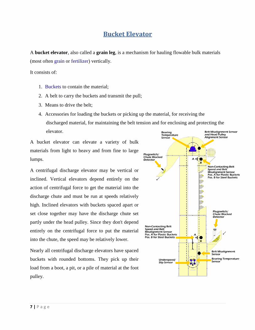
Bucket Elevator
A bucket elevator, also called a grain leg, is a mechanism for hauling flowable bulk materials
(most often grain or fertilizer) vertically.
It consists of:
1. Buckets to contain the material;
2. A belt to carry the buckets and transmit the pull;
3. Means to drive the belt;
4. Accessories for loading the buckets or picking up the material, for receiving the
discharged material, for maintaining the belt tension and for enclosing and protecting the
elevator.
A bucket elevator can elevate a variety of bulk
materials from light to heavy and from fine to large
lumps.
A centrifugal discharge elevator may be vertical or
inclined. Vertical elevators depend entirely on the
action of centrifugal force to get the material into the
discharge chute and must be run at speeds relatively
high. Inclined elevators with buckets spaced apart or
set close together may have the discharge chute set
partly under the head pulley. Since they don't depend
entirely on the centrifugal force to put the material
into the chute, the speed may be relatively lower.
Nearly all centrifugal discharge elevators have spaced
buckets with rounded bottoms. They pick up their
load from a boot, a pit, or a pile of material at the foot
pulley.

8 | P a g e
The buckets can be also triangular in cross section and set close to on the belt with little or no
clearance between them. This is a continuous bucket elevator. Its main use is to carry difficult
materials at slow speed.
Early bucket elevators used a flat chain with small, steel buckets attached every few inches.
Current construction uses a rubber belt with plastic buckets. Pulleys several feet in diameter are
used at the top and bottom. The top pulley is driven by an electric motor.
The bucket elevator is the enabling technology that permitted the construction of grain elevators.
A diverter at the top of the elevator allows the grain to be sent to the chosen bin.
TECHNICAL SPECIFICATION OF CHAIN BUCKET ELEVATOR
S.No. PARAMETERS UOM SCL
REQUIREMENT
(AS PER IS
7167:1974)
Design Data
01 Material to be handled Limestone
02 Bulk Density t/m3 1.2
03 Moisture % <6
04 Design Capacity tph 50
Bucket Details
01 Bucket Size (LxBxH) mm 305X190X230
02 Becket Pitch, S mm 320 to 400
Sprocket Details

9 | P a g e
01 Drive Sprocket PCD mm 500 to 760
02 Boot Sprocket PCD mm 355 to 585
Casing Details
01 Casing Size mm 1500x550
02 Boot Casing Thickness mm 8
03 Head casing thickness mm 6
04 Hood casing thickness mm 4
05 Flange thickness mm 6
Drive Detail
01 Motor Rating kw 7.5
02 Ratio 45:1
03 Plummer Block Make Masta/Premil
04 Coupling BC4 Tyre
Bucket elevator currently is facing two problems :-
1. Although it is designed for 45 TPH it only operates at 25 – 30 TPH at full load.
2. There is frequent damaging of Buckets as clearly shown in the picture taken
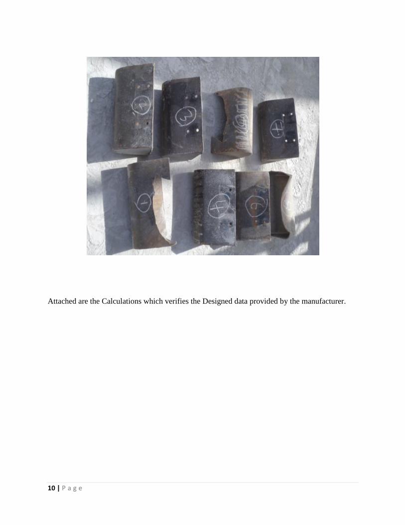
10 | P a g e
Attached are the Calculations which verifies the Designed data provided by the manufacturer.

11 | P a g e
Proof with Calculations and Simulation
Since the Buckets were designed for a load of 40 TPH they should not damage at 25 TPH , so I
decided to use Finite Element Method Simulation to check if there is some designing problem .
For this I designed the Buckets in Autodesk Inventor 3d CAD software .
Figure for the bucket drawn in Autodesk Inventor
12 | P a g e
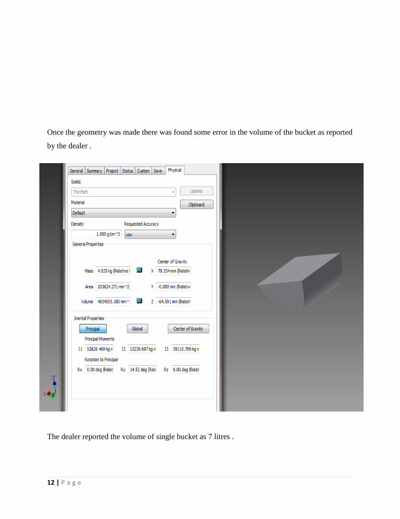
Once the geometry was made there was found some error in the volume of the bucket as reported
by the dealer .
The dealer reported the volume of single bucket as 7 litres .

13 | P a g e
However when calculated with inventor the correct volume was calculated as 4834505mm3
,
which equals 4.8 liters as clear from the picture above .
Damaging of Buckets
Since the Buckets were designed for a capacity of 45 TPH , they should not damage at 25 or 30
TPH . The Reason as cited by the people working in the plant was that the buckets were not
designed properly and they were weak . So I decided to verify the design of Buckets by using 3D
Finite Element Method again .
For this I used a software Ansys which is simulation driven Environment used for all types of
Mechanical purposes .
The Bucket was meshed with 3D Tetrahedral elements with 4 nodes each having 3 Degrees of
Freedom .
14 | P a g e
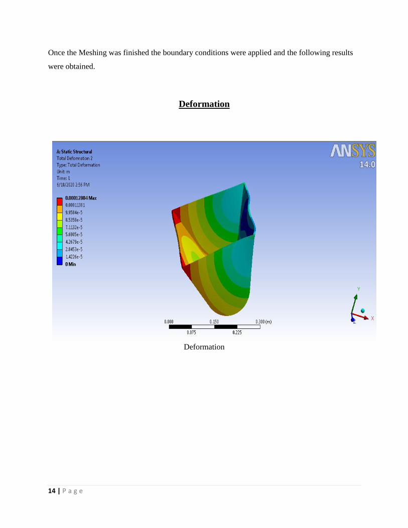
Once the Meshing was finished the boundary conditions were applied and the following results
were obtained.
Deformation
Deformation
15 | P a g e
Safety Factor
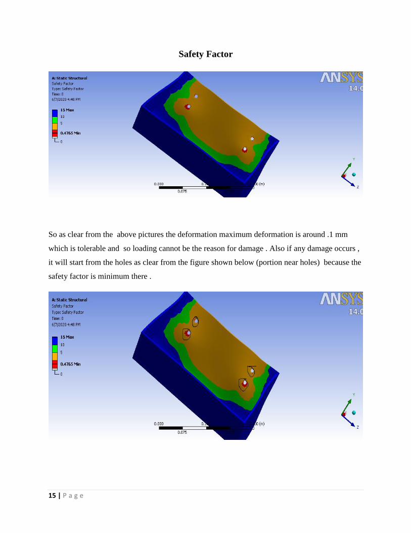
So as clear from the above pictures the deformation maximum deformation is around .1 mm
which is tolerable and so loading cannot be the reason for damage . Also if any damage occurs ,
it will start from the holes as clear from the figure shown below (portion near holes) because the
safety factor is minimum there .
16 | P a g e
So it is clear that the Deformation and Damage takes place in the same manner as predicted by
the Ansys software . This clearly shows that Buckets were properly designed but Problem is
different .
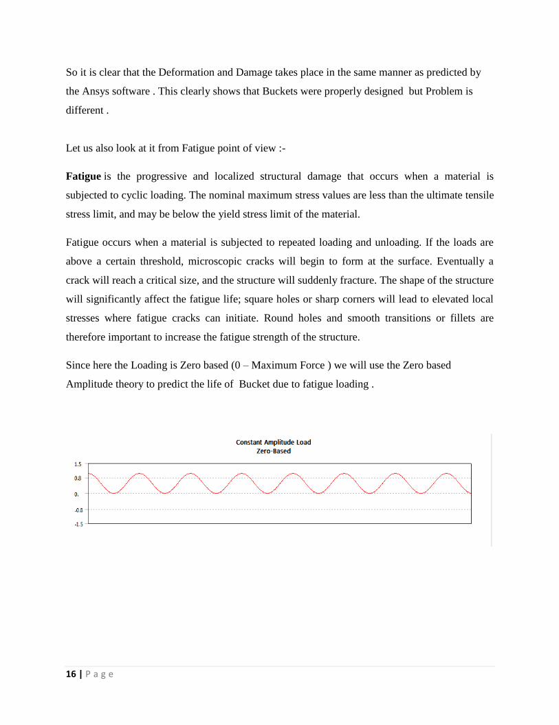
Let us also look at it from Fatigue point of view :-
Fatigue is the progressive and localized structural damage that occurs when a material is
subjected to cyclic loading. The nominal maximum stress values are less than the ultimate tensile
stress limit, and may be below the yield stress limit of the material.
Fatigue occurs when a material is subjected to repeated loading and unloading. If the loads are
above a certain threshold, microscopic cracks will begin to form at the surface. Eventually a
crack will reach a critical size, and the structure will suddenly fracture. The shape of the structure
will significantly affect the fatigue life; square holes or sharp corners will lead to elevated local
stresses where fatigue cracks can initiate. Round holes and smooth transitions or fillets are
therefore important to increase the fatigue strength of the structure.
Since here the Loading is Zero based (0 – Maximum Force ) we will use the Zero based
Amplitude theory to predict the life of Bucket due to fatigue loading .
17 | P a g e
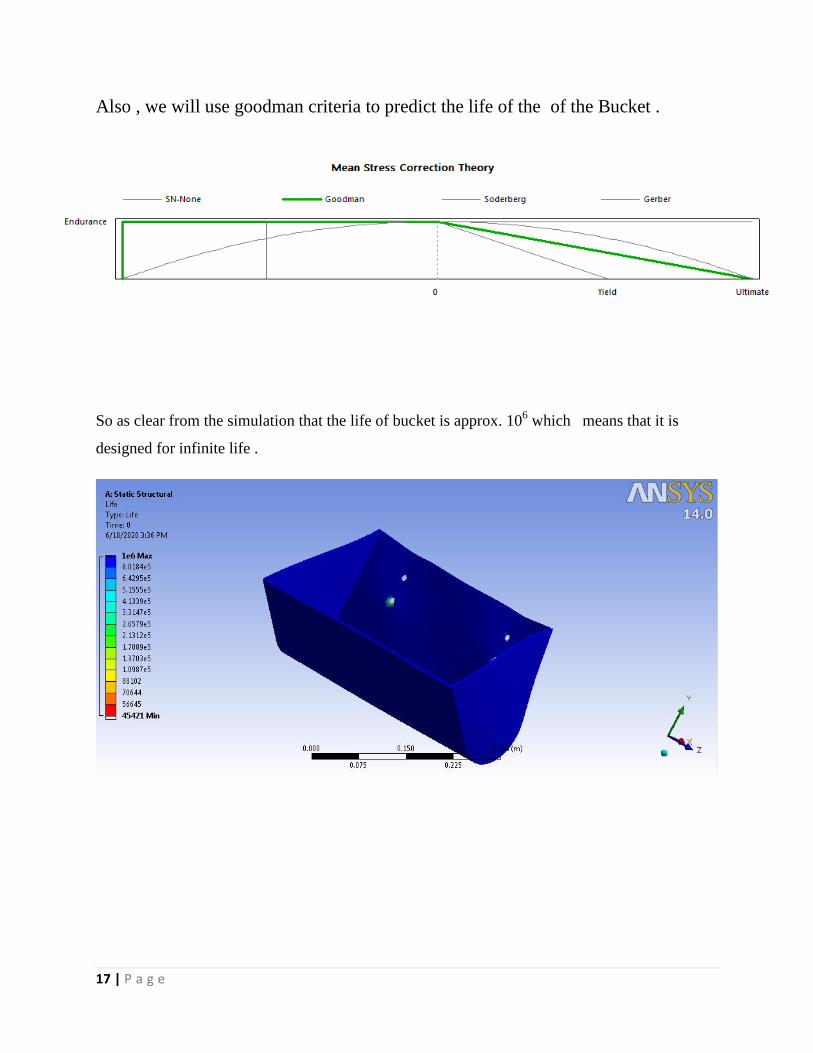
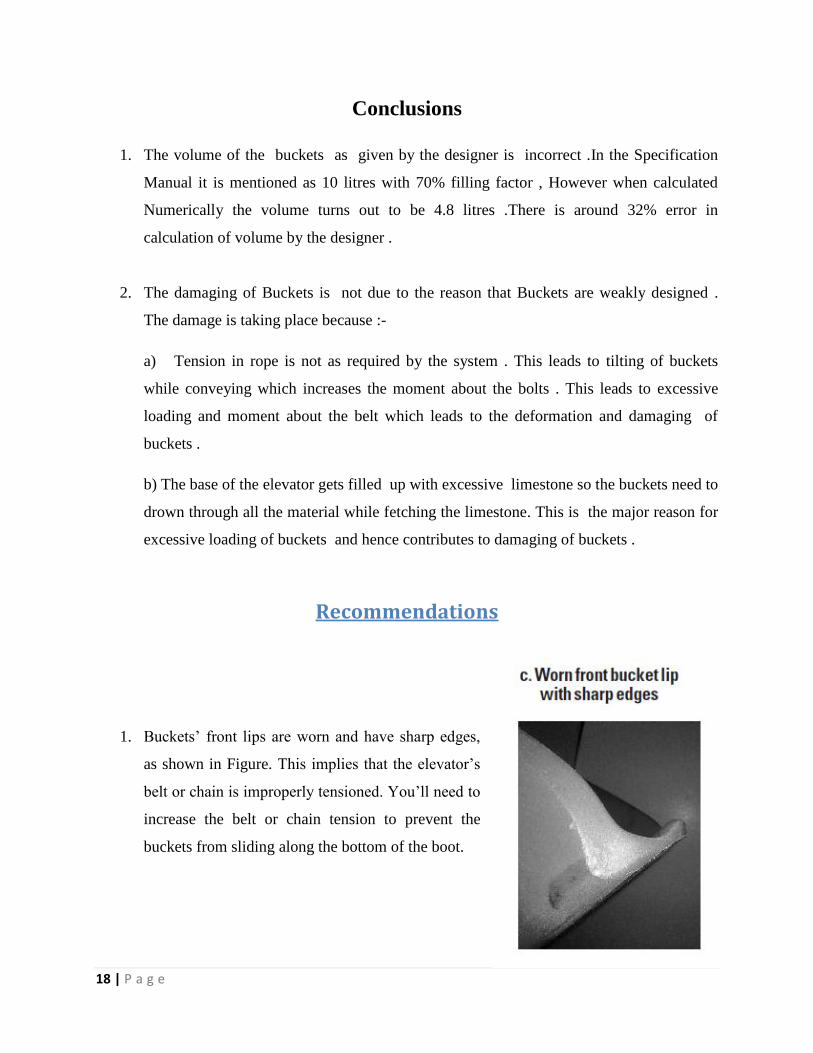
Also , we will use goodman criteria to predict the life of the of the Bucket .
So as clear from the simulation that the life of bucket is approx. 106 which means that it is
designed for infinite life .
18 | P a g e
Conclusions
1. The volume of the buckets as given by the designer is incorrect .In the Specification
Manual it is mentioned as 10 litres with 70% filling factor , However when calculated
Numerically the volume turns out to be 4.8 litres .There is around 32% error in
calculation of volume by the designer .
2. The damaging of Buckets is not due to the reason that Buckets are weakly designed .
The damage is taking place because :-
a) Tension in rope is not as required by the system . This leads to tilting of buckets
while conveying which increases the moment about the bolts . This leads to excessive
loading and moment about the belt which leads to the deformation and damaging of
buckets .
b) The base of the elevator gets filled up with excessive limestone so the buckets need to
drown through all the material while fetching the limestone. This is the major reason for
excessive loading of buckets and hence contributes to damaging of buckets .
Recommendations
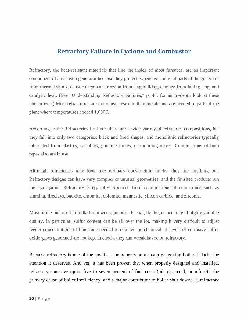
1. Buckets’ front lips are worn and have sharp edges,
as shown in Figure. This implies that the elevator’s
belt or chain is improperly tensioned. You’ll need to
increase the belt or chain tension to prevent the
buckets from sliding along the bottom of the boot.

19 | P a g e
2. Buckets’ sides are worn or scored, as shown in
Figure . This is again because of the reason that the
elevator’s belt or chain isn’t tracking properly. To
fix this, adjust the belt tracking across the head
pulley’s crown by increasing the belt or chain
tension to prevent the bucket from scraping along
the leg casing.
3. Buckets’ interior surface is worn, exhibiting a
sandblast effect, as shown in Figure . This means that
the material’s feed velocity into the bucket is too
high. To prevent this, you’ll need to reduce the
material’s infeed velocity, install baffles at the leg
entrance, or replace the existing buckets with more
abrasion-resistant urethane buckets.

20 | P a g e
4. Buckets’ front lips are stretched out or broken, as
shown in Figure 1f, or the bolts that secure the buckets
to the belt or chain are broken. This suggests that there
are obstructions inside the elevator or that the
elevator’s belt or chain is improperly tensioned. First,
check the elevator’s boot and throat-plate clearances
and each leg casing for any obstructions that the
buckets may be impacting, such as an open inspection
door or tramp metal. Next, increase the belt or chain
tension to keep it taut so that it doesn’t flap and allow
the buckets to hit the elevator’s interior or internal components. If necessary, install
impact-resistant nylon buckets.
5. Material doesn’t completely fill into the buckets or discharges from them too late or too
early (called backlegging) or not at all. This indicates that the buckets are filling or
discharging inefficiently, which diminishes the elevator’s throughput capacity. A solution

21 | P a g e
is to install vented buckets to improve the efficiency of bucket fill or discharge. Figure
above shows an example of a vented bucket.These buckets are available with various
numbers of vents in various configurations, depending on the application. For dense
materials such as flour, meals, or mash feeds, the bucket vents allow air to escape as the
bucket is filled. During discharge, the vents allow air to return into the bucket, preventing
a vacuum from forming that can hold material in the bucket and cause backlegging. For
extremely light materials such as alfalfa or bran, the bucket vents decrease the air
turbulence that can occur in the elevator up leg. Reducing the air currents minimizes the
circulatory pressure within the elevator, which can draw a light material through the
down leg and back to the boot. The elevator manufacturer or bucket supplier can help
determine the vent pattern best suited for the application .
6. The capacity can further be increased by redesigning the bucket elevator by decreasing
the pitch .Decrease in the pitch of buckets will lead to increase in the capacity of the
elevator . This will lead to redesigning of shaft , chain and the motor for the elevator .

22 | P a g e
Maintenance of bucket elevator
To properly maintain your centrifugal discharge bucket elevator, establish and follow a
preventive maintenance program that includes regularly scheduled inspections of the elevator
and buckets. Visually inspect these at least once a month, if not more, depending on how often
you use the elevator. Use the following checklist when inspecting your elevator and buckets:
• Check for broken, bent, or missing buckets and replace them.
• Retighten or replace the bolts and nuts that hold the buckets to the belt or chain.
• Verify proper alignment, tension, and physical condition of the belt or chain; check for wear,
stretching, or delamination.
• Check the throat plate and adjust if necessary.
• Look for wear on the head and boot pulleys.
• Clean inside the boot area and around the elevator and drive equipment.
• Inspect and lubricate all bearings and moving parts in the elevator.

23 | P a g e
Buckling of Boiler Secondary Super heater Panel
Sources that can lead to deterioration of steam superheater tubes of a high pressure boiler were
studied by a stress analysis, focused on internal pressure and temperature experienced by the
material at real operating conditions. Loss of flame control, internal deposits and unexpected
peak charge are factors that generate loads above the design limit of tube materials, which can be
subjected to strain, buckling, cracks and finally rupture in service. To evaluate integrity and
dependability of these components, the microstructure of selected samples along the superheater
should be studied by optical microscopy. Associated with this analysis, dimensional inspection,
nondestructive testing, hardness measurement and deposit examination were made to determine
the resultant material condition .
Introduction
Superheater tubes are surfaces for heat exchange, with the object of increasing the steam
temperature, after it comes from the boiler drum, to a value higher than saturation. This has
two basic purposes: to increase the thermodynamic efficiency of the turbine, in which the
steam will be expanded; and to make the steam free of humidity. In normal operation, the
boiler analyzed in this paper, named REDUC/SG- 2001, produces steam that is superheated by
approximately 200 °C at the inlet of the turbine. The steam flow has to be intense to permit the
heat absorption from the tube, avoiding deformation because of high temperature.
The superheater can be divided in two sections, primary and secondary, as in the boiler studied,
where the superheater tubes are within the radiation zone. As observed the secondary one
showed some tube deformation, which were large when observed at the last maintenance
shut down. This residual plastic deformation was observed on the outlet tube, attributed to
differential dilatation, because of different temperatures (ΔT), between the last two tubes,
anchored by spacers, and causing buckling. The objective was to determine the state of
integrity of the material in order to estimate a limit of deformation and then indicate the best

24 | P a g e
maintenance service for this equipment, which is critical to the continuity of the refinery
processes.
The strength of a boiler tube depends on the level of stress as well as on temperature when the
tube metal temperatures are in the creep range. Because an increase in either stress or
temperature can reduce the time to rupture, attention must be given to both factors during
investigation of a failure by a stress-rupture mechanism, which can be encountered in a
superheater. This can occur particularly by two mechanisms: short-term overheating and high
temperature creep. In the first one, a single incident, or a small number of incidents, exposes the
tube steel to an excessively high temperature (hundreds of degrees above normal) to the point
where deformation or yielding occurs. Overheating results from abnormal conditions such as loss
of coolant flow, internal oxide layer or flame incidence. The second one is either called long
term or extended overheating failures, which results from a relatively continuous extended
period of slight overheating, stress, or the accumulation from several periods of excessive
overheating. Creep deformation results in little or no reduction in wall thickness, but produces
measurable creep elongation or increases in diameter in ferritic steel tubes1.
The first published attempt to relate creep-life consumption of plant components to cavitation
(voids) was that of Neubauer and Wedel2. They characterized cavity evolution in steels at four
stages – i.e., isolated cavities, oriented cavities, linked cavities (microcracks) and microcracks –
as shown in Fig. 1. Based on observations on steam pipes in German power plants, they
estimated the approximate time intervals required for the damage to evolve from one stage to the
next under typical plant conditions. They formulated recommendations corresponding to the four
stages of cavitation (A, B, C, D).
Corrosion is another expected mechanism that can lead superheater tubes to failure. Localized or
generalized loss of thickness occurs because of corrosion by the products of combustion
(external) or from steam, especially when some contaminated water, coming from the drum,
flows through the superheater (internal) after some process abnormality. This causes increased
stress in a tube operating at a constant internal pressure. In addition, corrosion is a source for
overheating problems, by the formation of an oxide layer, which is a barrier to heat transfer. As

25 | P a g e
its thickness increases, metal temperatures must also increase to maintain a constant outlet
temperature. Typically, tube metal temperatures increase from 0.6 to 1.1 °C for each 30 μm of
internal oxide formed. Allowing for these changing conditions of metal temperature and stress
over time is key to reliable creep life prediction of alloy superheater tubes.
Another mechanism that can lead to failure is fatigue of the tubes. Pressure equipment, unlike
rotating machinery and aircraft structures, is not usually subjected to large numbers of load
cycles during its lifetime, and ductile metals can absorb surprisingly large strains for limited
numbers of cycles. When, however, the utmost in reliability and efficient utilization of material
is required it becomes necessary to calculate pressure stresses and thermal stresses in detail and
to determine whether or not fatigue failure is possible in a few hundred cycles. The fatigue curve
shows stress or strain versus cycles and which contains sufficient safety factors to give safe
allowable operating cycles for a given value of calculated stress. The stress values on the fatigue
curves should be directly comparable to stress values which a designer calculates using his usual
methods of analysis for pressure stress, thermal stress, stress concentration, etc.

26 | P a g e
Case Study of Buckling of Tubes

27 | P a g e

28 | P a g e
either at carbide boundaries and matrix. Aligned or coalesce dcarbides weren’t found, neither
microcracks, which indicates that the material didn’t reach an advanced stage of
creep, as described on the literature3. However, it was observed that in the pearlite phase, for the
T22 and T12 steels, a process of spheroidization of cementite had initiated. The
region that primarily suffers a flame incidence, sample 3, has the biggest percentage of
transformed pearlite, as shown in Fig. 4b. A smaller percentage is observed on sample 10,
Fig. 4a, which lay beyond the bottom refractory, at a lower temperature. Sample 8, where
buckling of the tube was observed, showed an intermediate degree of transformation of
cementite. The percentages for each sample are shown in Table 3. These percentages correspond
to a fraction of pearlite at the beginning of a microstructural deterioration caused by high
temperatures, but without significant change in mechanical properties.
Simulation of differential expansion of the last two tubes, caused by a ΔT of 50 °C, indicated a
lateral deflection of the hotter one, inducing deformation. The total deformation (εtotal), plastic
plus elastic, was 0.47%, near the two fixed spacers, superior and inferior. The same condition
leads to a total deformation of 0.26% in the middle of the vain. The assembly is shown in Fig.
5a, illustrating the deformation in the outlet tube. The model used for calculations with ANSYS
5.4 is shown in Fig. 5b.

29 | P a g e
For this condition, an apparent stress range, calculated by .εtotal.E, of 67000 psi occurs at the
most strained points, submitted to heating and cooling cycles during boiler starting and
shutdown. Applying this stress range to the graph of ASME section VIII, division 2 (appendix 5
– Design Based on Fatigue Analysis)9, corresponding to ferritic steels, it’s found that 1500 (one
thousand and five hundred) cycles would lead to nucleation of fatigue cracking. This is a long
time when compared to the operating time of a boiler. Doing the calculations in the opposite
direction, considering 100 (one hundred) cycles, which corresponds to approximately 50 (fifty)
years of operation, a total admissible deformation of 1.5% is found. This condition will occur
when the lateral deflection reaches 130 mm, a value that has to be adopted as a criterion to
change these superheater tubes.
Conclusions
1. According to the hardness results it was noted that the mechanical resistance of the material
has been preserved. Dimensional measurements and NDT did not show evidence of creep
damage.
2. The microscopic analysis of internal layer revealed the presence of deposits proceeding from
steam or water that passes to the first superheater. The thickness of the layer does not indicate
problems associated with material integrity or boiler efficiency.
3. The microstructural analysis revealed some spheroidization of cementite of pearlite, indicating
an initial state of high temperature damage of the material. Aligned pores or microcracks were
not found in the samples examined. These indicate that, for a period of twenty-three years of
service, the material showed a satisfactory state of integrity.
4. Simulations with ANSYS 5.4 software indicated the sources for deformations observed on the
studied assembly and the fatigue life associated with heating and cooling cycles. It was
concluded that, based on these kinds of damage, the maximum lateral deflection allowed is 130
mm, which can be a criterion to indicate the necessity of changing these tubes.
30 | P a g e
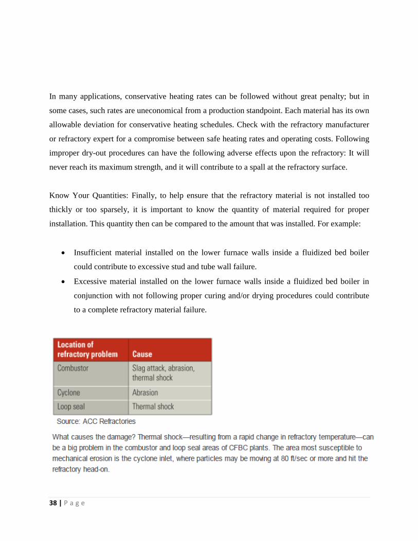
Refractory Failure in Cyclone and Combustor
Refractory, the heat-resistant materials that line the inside of most furnaces, are an important
component of any steam generator because they protect expensive and vital parts of the generator
from thermal shock, caustic chemicals, erosion from slag buildup, damage from falling slag, and
catalytic heat. (See "Understanding Refractory Failures," p. 48, for an in-depth look at these
phenomena.) Most refractories are more heat-resistant than metals and are needed in parts of the
plant where temperatures exceed 1,000F.
According to the Refractories Institute, there are a wide variety of refractory compositions, but
they fall into only two categories: brick and fired shapes, and monolithic refractories typically
fabricated from plastics, castables, gunning mixes, or ramming mixes. Combinations of both
types also are in use.
Although refractories may look like ordinary construction bricks, they are anything but.
Refractory designs can have very complex or unusual geometries, and the finished products run
the size gamut. Refractory is typically produced from combinations of compounds such as
alumina, fireclays, bauxite, chromite, dolomite, magnesite, silicon carbide, and zirconia.
Most of the fuel used in India for power generation is coal, lignite, or pet coke of highly variable
quality. In particular, sulfur content can be all over the lot, making it very difficult to adjust
feeder concentrations of limestone needed to counter the chemical. If levels of corrosive sulfur
oxide gases generated are not kept in check, they can wreak havoc on refractory.
Because refractory is one of the smallest components on a steam-generating boiler, it lacks the
attention it deserves. And yet, it has been proven that when properly designed and installed,
refractory can save up to five to seven percent of fuel costs (oil, gas, coal, or refuse). The
primary cause of boiler inefficiency, and a major contributor to boiler shut-downs, is refractory

31 | P a g e
failure. Discovering why a refractory material fails is a complex problem because failure is not
caused by just one factor, but rather a combination of the following factors:
The material selected does not match the environment that exists (i.e., reducing
atmosphere)
The material selected does not match the fuel being burned (i.e., the amount of alkali,
sulfur, hydrocarbons, vanadium, or moisture present in the fuel)
The material was improperly stored, mixed, installed, cured, and/or dried
The material selected did not match the environment created after the burning of the fuel
(i.e., ash and slag)
Slag can reduce furnace heat absorption, raise exit gas temperatures, increase attemperator spray-
flow temperature, and interfere with ash removal or equipment operation. Slag is the formation
of molten ash that is either partially fused or re-solidified ash deposits (ash fusion), formed based
on the ash temperature and composition.
For slag to adhere to a surface and form deposits, the ash particles must have a viscosity low
enough to wet the surface. If iron is present, it will raise all four values of ash fusion
temperatures (initial deformation, softening, hemispherical, and fluid). The greater the iron
content found in the ash, the greater the difference in ash fusibility between the oxidizing and the
reducing condition.
There are two kinds of ash. Coal ash is the residual product left after burning of the fuel. Oil ash
is the residual product left after burning off oil. Coal ash that has a low fusion point and high
basic oxide content can be very corrosive to refractory materials; and oil ash that contains
vanadium, sulfur, alkalis, and hydrocarbons can cause severe problems to refractory materials.
Vanadium can act as a catalyst, forming a low-melting alkali-silica compound that could react
and break down the basic components of a refractory material.
Sulfur can combine with lime and iron oxides found in some refractory materials and can reduce
material strength. In the presence of moisture, sulfur also could form sulfurous and sulfuric
acids, which could react with the basic components of a refractory material.
32 | P a g e
Alkali such as sodium (Na) and potassium (K) can chemically react with silica found in some
refractory materials.
Hydrocarbons, in conjunction with a reducing atmosphere (which refers to the amount of air
required for proper fuel combustion and is usually added to the combustion process in another
location), can react with iron oxides and form large carbon deposits in the refractory material.
This eventually could cause a spall (loss of fragments or pieces) on the refractory surface.
Finding the Root Cause of a Refractory Failure
STEP 1: DISCOVERY PROCESS
It is necessary to collect and document some basic information. In many cases, the discovery
process requires interviews with plant and installation personnel. These professionals know first-
hand about the refractory process. The following information should be identified and
documented:
Material samples and data sheets of the existing brick or refractory lining—this
information may be supplied by the purchasing agent or by the plant engineer;
Material samples of the ash clinkers and slag—samples may be supplied by maintenance
or engineering personnel from the plant;
Chemical analysis of the fuel being burned (coal, startup oil, refuse, wood, steel,
aluminum, etc.)—this information may be supplied by the plant engineer;
Storage location and duration of the storage prior to installation—this may be supplied by
the plant or the installation contractor;
Manufacture date of the refractory material—this information may be supplied by the
refractory manufacturer;
Ambient condition at the time of the installation—this should be supplied/verified by
both the plant personnel and the installation contractor;
How much material was installed—this information may be supplied by plant personnel
and/or the installation contractor;
How it was installed or applied (pneumatically, toweled, poured, shotcrete, etc.)—this
may be supplied by the plant or the installation contractor
33 | P a g e
How the material was cured and/or dried and what procedures were followed—this
information may be supplied by the plant and/or the installation contractor.
Step 2: Examine The Existing Material And Testing
The existing material (or the lack thereof) should be examined for signs that may indicate the
root cause of the failure. When looking at an existing refractory lining or photos of the existing
lining, keep in mind the following questions:
Did the material fail due to thermal shock (large sections of the top surface area sheared
away)?
Is there any evidence that the materials had been exposed to excessive temperatures
(excessive shrinkage, glazing, etc.)?
Is there any evidence of mechanical abuse (broken and jagged edges or holes)?
Did the material fail due to the operation of the equipment, furnace, or boiler?
Was the refractory material installed improperly (i.e., porous or popcorn-like texture)?
Collecting Samples for Testing: Samples of the existing refractory material should be gathered
and sent out for a cold crush test, which will verify the strength of the installed material. The
results can be compared to the manufacturer’s material data sheets. If the strength of the existing
installed material is low, it is probable that the mix was too wet when installed. Samples of the
existing slag and ash clinkers should be gathered and sent out for chemical analysis. The slag
samples should also have a pyrometric cone equivalent (PCE) test performed to verify the
minimum temperature that the refractory may have been exposed to.
Step 3: Calculate the Base To Acid Ratio
The next step is to document the environment to which the refractory material was exposed. One
way to do this is by calculating the base-to-acid ratio (b/a), using values taken from the
information received from the chemical analysis test mentioned in Step 2. This b/a value will
give a starting point as to what type of refractory material should have been chosen.
34 | P a g e
Here is one way to calculate the base-to-acid ratio:
When the base-to-acid ratio is less than or equal to .25, it indicates an acid condition. An
acid condition would indicate that a SiO2 type refractory should be considered.
When the base-to-acid ratio is greater than .25 but less than .75, it indicates a neutral
condition. A neutral condition would indicate that an Al2O3, SiC, orchrome type
refractory material should be considered.
When the base-to-acid ratio is greater than or equal to .75, it indicates a basic condition.
A basic condition would indicate that an MgO or Dolomite type refractory material
would be considered.
Step 4: The Review Process
Now it is time to analyze all the information gathered in Steps 1 and 2. All of the service
conditions must be reviewed and analyzed thoroughly in order to see how they could affect the
installed/failed material. This includes the fuel or raw materials being burned, startup fuel used,
ash and slag content, gas temperatures, and plant operations and procedures. For example:
Moisture content in the fuel can affect the refractory material. High moisture content or
combined moisture content in the fuel with a reducing atmosphere can cause a separation of
silicon carbide base materials (grain). This separation can occur when the total percentage of the
moisture content found in the fuel is greater than fifteen percent, or when the combined total
percentage of the moisture content in the coal and the reducing atmosphere percentage are
greater than fifteen percent. Certain amounts of chemicals (iron oxide, potassium, or sulfur)
found in the fuel, slag, or ash could react with cements (calcium-aluminate) that are present in a
cement-bonded type refractory, especially if a reducing atmosphere is present.
Certain startup fuel (oils) may contain vanadium, which could react with the silica and lime in
the cement found in a cement-bonded type refractory. When vanadium is present, it can cause a
chemical attack and surface failure, or cause a complete refractory failure (no refractory present).

35 | P a g e
Step 5: Review Of Installation Procedures
The final analysis also must take into account proper installation procedures. All of the items
listed below could prevent a refractory material from reaching its proper strength. A refractory
material that is not able to reach its designed strength has the highest potential for failure.
Properly Manufacture Date and Storage: Refractory material should be manufactured in the
proper time period based on the installation date and manufacture date. One year is
recommended for a cement-bonded material used for conventional seals inside boilers, and three
months or less for materials used in high temperature and abrasion areas such as those found
inside fluidized bed boilers, cyclone fire boilers, or wet bottom ash hoppers. Refractory material
always should be stored in dry, well-ventilated conditions. Use fresh refractory materials and
follow proper storage procedures to ensure that the refractory will not lose strength.
Proper Water for Mixing: Many common industrial compounds can easily contaminate a
refractory mix and seriously affect its strength. Certain salts can react with the refractory cement
to make the material almost useless. It is recommended by most refractory manufactures that
potable water (suitable for drinking) should be used for mixing. The use of the wrong type of
water (e.g., river water) will hinder the ability of the refractory material to reach its proper
strength.
Equipment and Pot Life: Using the right type of mixer, following proper mixing procedures, and
being aware of the materials’ pot life also must be considered. Using the wrong mixer or
pneumatic gun also could impact the strength of the refractory material. For example:
Many pneumatically applied refractory materials require the material to be pre-wetted
prior to the actual mixing and installation. If the installing contractor had used a
continuous feed mixer (i.e., one that adds dry material into a hopper and the water is

36 | P a g e
added only at the nozzle), the material could not be pre-wetted do to the nature or
characteristics of using a continuous feed mixer. This could reduce the strength of the
installed material.
Every refractory material has a pot life, which designates how long a mixed refractory
material can be used after mixing. Failure to follow recommended pot life times could
result in a refractory material not reaching its proper strength. If the pneumatic
installation of the refractory is interrupted for a period of time longer than the
recommended ―pot life‖ time period, the material found in the mixer and hoses should be
discarded and not re-used.
Ambient Conditions: Cold or hot weather could adversely affect the strength of a refractory
material. It is recommended by most refractory manufacturers that the final mix temperature
should be in a specific range. Though they all differ slightly, it is recommended that the final mix
temperature should be in a range of 40° to 90° F. It is also very important to protect the installed
materials from freezing for a minimum of forty-eight hours or until thoroughly dried. Failure to
take into consideration the ambient conditions at the time of installation could impact the ability
of the refractory material to reach its proper strength.
The following formula is one way to estimate/adjust the variables relative to mixing a refractory
material (e.g., water temperature, air temperature, storage temperature):
X=[(W * T) + .22 (Wc * Ts)] / (W+.22Wc)
W = weight of water (a quart of water weighs 2.08 pounds)
Wc = weight of dry refractory
T = temperature of water (degrees F)
Ts = temperature of solids (degrees F)
X = temperature of mixed refractory (degrees F)
Using the above formula and knowing the ambient conditions at the time of installation can help
determine if the installed material was adversely affected by the ambient conditions.
37 | P a g e
Curing Procedures: Only after the refractory material has been cured and/or dried will it be at its
proper strength. Almost all refractory materials (except those that are phosphate-bonded) must be
cured prior to the drying process. Failure to properly cure a cement-bonded refractory material is
the number one contributor to refractory failure and lack of longevity. Curing allows the
chemical action to take place inside the refractory and helps ensure that the refractory can reach
its maximum strength when properly dried. It is recommended that the surface of the refractory
be kept moist (curing compound, wet canvas bags, or spraying water) or the surrounding
atmosphere humid for a period of at least twenty-four hours.
Drying Procedures: The dry-out or bake-out of the refractory will take place after the curing
period and removes all mechanical and chemical water left in the installed material. It allows the
refractory material to reach its proper strength. Unlike the curing of refractory, which is done
right after the installation (usually by the installing contractor), the dry-out can be completed any
time. This does not apply to phosphate-bonded refractory materials, however, as a phosphate-
bonded material must be cured and dried at the same time. A phosphate-bonded material must be
dried within the first two to three weeks after installation because such a material will begin to
absorb moisture from the surrounding atmosphere. Eventually, over a period of two or three
weeks, the material will begin to slump and fall off.
New lining should be heated gradually to let the moisture escape and reduce internal stresses.
The rule of thumb is to base the hold time on the thickness of the thickest area of refractory
lining found on the entire work project. For example, if the thickest area is four inches thick, the
hold time is four hours.
The following heating schedule is of a general nature for ideal conditions for a one-inch-thick
refractory lining on fluidized bed furnace walls:
Raise temperature at 75°F per hour to 250° to 400°F range. Hold for two hours at 250° to
400°F
Raise temperature at 75°F per hour to 600° to 800°F. Hold for two hours
Raise temperature at 75°F per hour to 1,050° to 1,200°F. Hold for two hours
Raise temperature at 75°F per hour to operating temperature
38 | P a g e
In many applications, conservative heating rates can be followed without great penalty; but in
some cases, such rates are uneconomical from a production standpoint. Each material has its own
allowable deviation for conservative heating schedules. Check with the refractory manufacturer
or refractory expert for a compromise between safe heating rates and operating costs. Following
improper dry-out procedures can have the following adverse effects upon the refractory: It will
never reach its maximum strength, and it will contribute to a spall at the refractory surface.
Know Your Quantities: Finally, to help ensure that the refractory material is not installed too
thickly or too sparsely, it is important to know the quantity of material required for proper
installation. This quantity then can be compared to the amount that was installed. For example:
Insufficient material installed on the lower furnace walls inside a fluidized bed boiler
could contribute to excessive stud and tube wall failure.
Excessive material installed on the lower furnace walls inside a fluidized bed boiler in
conjunction with not following proper curing and/or drying procedures could contribute
to a complete refractory material failure.
39 | P a g e
Recommendations
To solve the problem, many CFB plants in India have tried a specially designed, phosphate-
bonded aluminous plastic called Accplast 80, and the results have been excellent. Accplast 80
has better physical and thermal properties than typical refractory, and its chemical bonding deters
slag from sticking to it. As a result, the refractory resists when slag is dislodged. In addition,
Accplast 80 lasts significantly longer— sometimes as much as twice as long—than other
refractory materials.
However, it isn't easy to install any phosphate-bonded plastic such as Accplast 80 on a CFBC
boiler. One of the biggest challenges is keeping the material in position until it is hardened by
heating to 572F. Until it reaches that temperature, Accplast 80 can lose its shape and slump. To
prevent that from happening, ACC Refractories recommends holding it in place with ceramic
anchors until it hardens.
Following are several other steps that should be taken when installing plastic refractories:
Provide retainers at predetermined intervals, especially in sloped areas.
Ensure that any spaces between ceramic anchors are completely filled.
Equally space the ceramic anchors, use wooden wedges to give them a tight fit, and
properly seat the anchors on the support collar to avoid point loading.
Replace any misaligned anchors.
Completely fill the shuttering with plastic before placing the next set of forms.
Remove the shuttering piece by piece after checking for slumping.
Remember to remove any wooden forms before reheating the boiler.
Re-ram the plastic after removing the shuttering to ensure that it is properly compacted
around anchors.

40 | P a g e
Lime Handling System
BRIEF SYSTEM DESCRIPTION:
Lime stone collected from various hoppers of cyclone zone is conveyed to lime stone bunker
through dense phase pneumatic conveying system.
Complete lime handling system can be distributed in two systems:
i) Lime Collection / Conveying System
ii) Bunker Unloading system
Complete lime handling system is controlled & monitored from DCS system. All the signals will
be processed in the DCS only.
All controls such as system start/stop selector switches, Push buttons etc. shall be devised on
pneumatic panel. All indications such as System ON, Conveying ON, and Cycle ON etc. shall be
flashed on HMI screen (. Faults such as System fault, Line Block etc. shall be annunciated on
HMI screen.
Lime Conveying Systems:
The complete Lime handling system consists of the following hoppers for
collection of lime.
System – 101, 102, 103, 104, 105 & 106:-
There are 6 no. of systems. All these systems are master system, in which every two systems in
Cyclone zone are connected with a common pipeline. So there are three sets of two systems in
each (system 101 & 102, system 103 & 104, 105 &106). Firstly system no. 101, 103 & 105 will
convey & after conveying of lime stone from these systems, the other systems 102, 104 & 106
will convey and So system no.(101, 103 & 105) and system no. (102, 104 & 106) will work
alternatively according to the set up time.
So the conveying material through system no (101 & 102) will be conveyed to the lime stone
Bunker through the diverter valve with knife gate valve (1A & 1B).
41 | P a g e
The conveying material through system no (103 & 104) will be conveyed to the lime stone
Bunker through the diverter valve with knife gate valve (2A & 2B).
The conveying material through system no (105 & 106) will be conveyed to the lime stone
Bunker through the diverter valve with knife gate valve (3A & 3B). Hence in this way, all
conveying material will be conveyed to the lime stone bunker.
Working of the system In this firstly, the lime stone material is fed to the lime stone hopper. After filling of hopper, the
Air vent valve is opened. After opening this valve the inlet dome valve (DSV) is opened & the
material starts loading into the transporting vessel. After filling of lime stone into the vessel, the
higher level transmitter (LT) senses the high level of the vessel and then the dome valve & air
vent valve is closed within a gap of 2 to 3 seconds. After that all the conveying lines will be
opened & conveying of Lime Stone will start by closing the outlet dome valve. Then back
pressure will rise in the transporting vessel due to conveying lime stone in the system. When the
back pressure will reach the set point then the outlet dome valve will be opened & conveying
will start. When the low level of material is reached then the low level transmitter (LT) senses
the level & then the outlet dome valve will be closed. After then, the Air vent valve will be
opened. After some time, the inlet dome valve will be opened. Thus this process will repeat
again as same as the above process.
42 | P a g e
Pneumatic Conveying Systems for Bulk Materials
Many material-handling plants transfer large quantities of materials, often over long distances.
As a result, the conveying system’s power consumption is of prime importance. In pneumatic
conveying, power consumption is a function of the system design, transfer rate, and convey
length. Therefore, a conveying system that transfers 100 tn/hr of a bulk material over a distance
of 200 m uses about the same amount of power as a system of the same design that conveys 200
tn/hr of the same material over a distance of 100 m. Consequently, it is evident that the length of
a pneumatic conveying system has the same impact on power consumption as does rate.
Traditionally, bulk materials have been conveyed by inefficient pneumatic conveying systems.
However, modern material-handling plants require more-efficient conveying systems to reduce
power costs. In addition to reducing electricity costs, lowering power consumption offers many
other benefits. First, conveying systems that use less power require less maintenance.
Recommendations
There are four 45 degree bends that can be avoided as each 45 degree bend is equivalent
to almost 20ft increment in straight length of pipe . Also after each bend , the particle
velocity decreases to 80% of original speed .So I strongly recommend to remove those 4
bends .
We can install boosters in the pipeline at certain points so as to provide excess air
pressure at bends and far from the compressor . This will aid the existing pressure and
help in the transporting of material easily .

43 | P a g e
Do the CFD Analysis of the pipes as there can be separation of flow which can result in
back flow of air which can reduce the capacity of the conveying system .
44 | P a g e
Boiler & Combustor Water wall tube Leakage
Water – Tube boiler plant is much less tolerant of high TDS levels and even
less so as the pressure increases. This is due to a number of reasons:-
Water Tube boilers have a limited surface area in the steam drum,
relative to evaporation rate . This results in very high steam release rates
per unit of water area, and turbulence.
Water Tube boilers tend to be high rated, over 500 tonnes of steam per
hour . This means that even a small percentage blowdown can represent
high mass to be blow down .
Water Tube Boilers tend to operate at higher pressure, around 150 bar or
more .The higher the pressure the greater the energy contained in the
blowdown . Higher pressure also means higher temperatures. This means
that the materials used for construction will be subjected to higher
thermal stresses and be operating closer to their metallurgical limitations.
Even a small amount of interval contamination hindering the heat transfer
from tubes to water may result in tubes overheating .
Water tube boilers often incorporate a superheater .
The dry saturated steam from the steam drum may be directed to a
superheater tubes situated in the highest temperature area of the furnace.
Any carryover of contaminated water with the steam would coat the
inside of superheater tubes and inhibit the heat transfer with potentially
disastrous results.

45 | P a g e
The water circulation is not proper and results in the local over heating.
All this imlpies :-
High quality water treatment is essential for the safe operation of
this type of plant .
It may be economically viable to invest in a water treatment palnt
that will minimize blow down rates.
The water circulation should be highly monitored in the tubes
during startup so that tubes may not get overheated and there is
proper heat transfer from the tubes to the water flowing inside .
In each of these cases, the selection will often be a demineralization or
a reverse osmosis plant.
However , Shree Mega power has its own Water demineralization plant. But it still
faces these problems of fouling and overheating of tubes leading to breakages .
The following observations were taken from the DM Plant on 15th
June regarding
the quality of water :-
Water Quality Parameters
PH 9.8
Conductivity 20.76
Silica .45
Phosphate 1.19
Iron .02
46 | P a g e
Case Study: Superheater tube burst
Phenomenon:
There is the sound of the steam spout and the feed water flow is larger than the steam flow.
The furnace negative pressure decreases or changes to positive pressure and the superheated
steam pressure decreases.
Reason:
The fouling happens inside the furnace or the foreign substances chocked the tube to affect the
heat transmission.
The erosion happens on the outer wall of the tube or the corrosion happens due to high
temperature.
The steam temperature or the wall temperature is beyond the limit for long time.
The tube material quality is not up to mark or the welding quality may have problem or the soot
blowing is not functioning properly.
Measurement:
If the tube burst is not serious and then it is permitted to operate the boiler for a certain time
but the load should be reduced and prepare for the shutdown.
If the tube burst is seriously:
a) Maintain the operation of the ID fan to control the bed temperature decreasing speed not
to be beyond the specified value.
b) Maintain the feed water supply as less as possible to maintain the normal water level.
c) Other operations according to normal cases.

47 | P a g e
Recommendations
The allowable limits of PH of water that should be used in power plants should be
around 7-8.5 or maximum 9. However the data clearly showed that that PH level
is 9.8 as of 15th June. The boiler water and the feed water quality is not up to the
mark for a long time and has resulted the fouling inside the tube and the further
resulted in increasing of the resistance locally to form the local over heated.So this
results into a lot of fouling and deposition on the interior of tubes leading to
improper heat transfer which further leads to overheating of tubes leading to their
failure. So I recommend to strictly maintain PH levels of water to be used in the
boiler.
When the water wall damage is not serious:
a) Increase the feed water flow to maintain the drum water level and then operate
the boiler at lower load or shutdown the boiler as per the normal procedures.
b) If the combustion is not stable the oil burner should be started to provide the
support.
If the water wall is seriously damaged and not possible to maintain the normal water
level:
a) Emergency shutdown the boiler and stop the feed water supply to the boiler.
b) Maintain the operation of the ID fan to remove the steam inside the boiler and if
the bed temperature decreasing speed is beyond the permissible value and then
stop the ID fan.
c) After the shutdown of the boiler immediately remove the bed material.