improved performance of an adjustable speed drives during voltage sag condition
TRANSCRIPT

8/8/2019 Improved Performance of an Adjustable Speed Drives During Voltage Sag Condition
http://slidepdf.com/reader/full/improved-performance-of-an-adjustable-speed-drives-during-voltage-sag-condition 1/11
S.S.Deswal et. al. / International Journal of Engineering Science and Technology
Vol. 2(6), 2010, 2445-2455
IMPROVED PERFORMANCE OF AN
ADJUSTABLE SPEED DRIVES DURING
VOLTAGE SAG CONDITIONS.S.DESWAL*
Assistant Professor, EEE Department,
Maharaja Agrasen Institute of Technology,Sector-22, Rohini, Delhi-110086, India
RATNA DAHIYAAssociate Professor, Department of Electrical Engineering,
NIT,Kurukshetra, kurukshetra, Haryana-136119, India
D.K.JAINDirector(Technical),
Guru Premsukh Memorial College of Engineering,Budhpur, Delhi-110036, India
Abstract:
Voltage sags normally do not cause equipment damage but can easily disrupt the operation of sensitive loads
such as electronic Adjustable Speed Drives (ASD’s). Voltage sags cause a momentary decrease in DC-link
voltage triggering an under voltage trip leading to nuisance tripping of adjustable speed drives (ASD’s)employed in continuous-process industries which contributes to loss in revenue. A practical ride-through
scheme for an adjustable speed drives based on supercapacitor during voltage sag has been presented in this paper. The supercapacitor maintains the ASD dc bus voltage under voltage sag condition. Energy storage
module is connected to support the DC-link voltage during power system faults. The performance of ASD’s
under normal and power system faults is first simulated in MATLab Simulink and then experimentally verified.
The Data AcQuisition boards (DAQ) of National Instruments along with LabVIEW software have been used torecord the observed waveforms.
Keywords : Adjustable speed drives, Low voltage ride-through capability, Voltage sags, Supercapacitor, Ultracapacitor.
1. Introduction
Adjustable Speed Drives (ASD’s) used in a wide variety of industrial applications. The benefits that might be
provided by the ASD’s are the reason for their widespread use by the industry. Despite of its importance to the
process operation, the ASD’s are sensitive to voltage sags. Undervoltage and overcurrent often follow voltage
sags which may cause the ASD’s to trip bringing about the halt of the productive process and revenue losses.
The ASD’s may also operate inappropriately resulting on load torque and load speed variations since the controlof the current and of the output voltage are dependent on the inverter DC voltage level which decays during
voltage sag [1], as shown in eqn(1).d c L r
d c
m o t in v
d V T V C
d t
(1)
Thus, the decrease rate of the dc bus voltage dV dc /dt depends on the capacitance C , the voltage Vdc across the
capacitor at the beginning of the voltage sag, the load torque T L, the motor speed ωr , the motor efficiency ηmot .
Different approaches to improve the ASD’s ride through by increasing the average voltage of the DC-link have been proposed [1], [5], [6], [7], [8]. The methods include the addition of capacitors to the DC- link [6], the
regenerative mitigation which converts the kinetic energy from the motor and load into electric energytransferring it to the ASD’s DC-link [1], the connection of the neutral conductor of the supply source to the
midpoint of the DC-link through a controlled switch [8], and the application of boost converters [1], [5], [7].
ISSN: 0975-5462 2445
8/8/2019 Improved Performance of an Adjustable Speed Drives During Voltage Sag Condition
http://slidepdf.com/reader/full/improved-performance-of-an-adjustable-speed-drives-during-voltage-sag-condition 2/11
S.S.Deswal et. al. / International Journal of Engineering Science and Technology
Vol. 2(6), 2010, 2445-2455
This paper presents a proposed topology to improve the low voltage ride-through capability of an adjustable
speed drive via experimental and simulation results. The system is tested under symmetrical and asymmetricalvoltage sag conditions in order to assess the contribution of the supercapacitor as an energy storage device to
improve the ASD’s operation under voltage sags.
The typical duration of voltage sags are between 0.5 to 30 cycles or 8ms to 0.5s. Voltage sags, classified astype A, are the most severe ones as they cause the larger amount of energy withdraw from the dc bus, and are
more likely to trip the ASD’s under voltage protection. The asymmetric voltage sags usually have at least one
line supply voltage which keeps the DC-link voltage above the under voltage protection level. Nevertheless,voltage sag type A is the least severe as far as the over current level is concerned. On the other hand, voltage
sags type B, caused by one-phase faults, are accountable for the most severe sags as far as over current are
concerned and the least severe as for the dc bus under voltage threshold level [ 5], [10]. It has been withdrawnfrom [5] that tests with voltage sag type A can set the under voltage protection level and tests with voltage sag
type B can set the over current protection level of an ASD’s.[11-12]
2. Energy Storage Systems
Energy storage systems, also known as restoring technologies are used to provide the electric loads with ride-through capability in poor Power Quality (PQ) environment. Recent technological advances in power
electronics and storage technologies are turning the restoring technologies one of the premium solutions to
mitigate PQ problems. The first energy storage technology used in the field of PQ, yet the most used today, is
electrochemical battery. Although new technologies, such as flywheels, supercapacitors and superconducting
magnetic energy storage (SMES) present many advantages, electrochemical batteries still rule due to their low price and mature technology.[8-9,13-14]
2.1. Flywheels
A flywheel is an electromechanical device that couples a rotating electric machine (motor/generator) with arotating mass to store energy for short durations. The motor/generator draws power provided by the grid to keep
the rotor of the flywheel spinning. During a power disturbance, the kinetic energy stored in the rotor is
transformed to DC electric energy by the generator, and the energy is delivered at a constant frequency andvoltage through an inverter and a control system. Traditional flywheel rotors are usually constructed of steel and
are limited to a spin rate of a few thousand revolutions per minute (RPM). Advanced flywheels constructed
from carbon fiber materials and magnetic bearings can spin in vacuum at speeds up to 40,000 to 60,000 RPM.The stored energy is proportional to the moment of inertia and to the square of the rotational speed. High speed
flywheels can store much more energy than the conventional flywheels. The flywheel provides power during a
period between the loss of utility supplied power and either the return of utility power or the start of a back-up
power system (i.e., diesel generator). Flywheels typically provide 1-100 seconds of ride-through time, and back-
up generators are able to get online within 5-20 seconds.[9,15-16]
2.2. Supercapacitors
Supercapacitors (also known as ultracapacitors) are DC energy sources and must be interfaced to the electric
grid with a static power conditioner, providing energy output at the grid frequency. A supercapacitor provides power during short duration interruptions or voltage sags. Medium size supercapacitors (1 MJoule) are
commercially available to implement ride-through capability in small electronic equipment.
2.3. SMES
A magnetic field is created by circulating a DC current in a closed coil of superconducting wire. The path of the coil circulating current can be opened with a solid-state switch, which is modulated on and off. Due to the
high inductance of the coil, when the switch is off (open), the magnetic coil behaves as a current source and will
force current into the power converter which will charge to some voltage level. Proper modulation of the solid-
state switch can hold the voltage within the proper operating range of the inverter, which converts the DC
voltage into AC power. Low temperature SMES cooled by liquid helium is commercially available. Hightemperature SMES cooled by liquid nitrogen is still in the development stage and may become a viable
commercial energy storage source in the future due to its potentially lower costs. SMES systems are large and
generally used for short durations, such as utility switching events.The high speed flywheel is in about the same cost range as the SMES and supercapacitors and about 5 times
more expensive than a low speed flywheel due to its more complicated design and limited power rating.
Electrochemical battery has a high degree of mature and a simple design. Below a storage time of 25 seconds
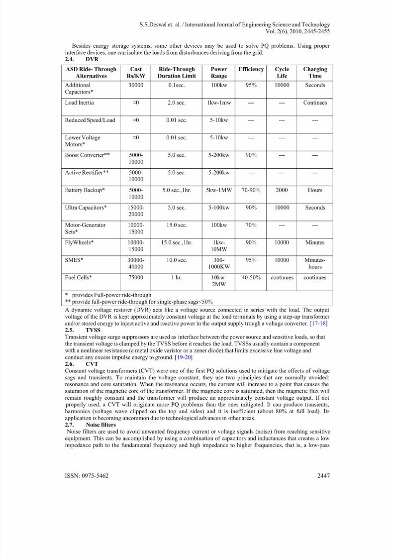
the low speed flywheel can be more cost effective than the battery.Table 1, shows a comparison of the different storage technology in terms of specific power and specific
energy. [3]Table-I Comparison of different ASD’s Ride-through Alternatives
ISSN: 0975-5462 2446
8/8/2019 Improved Performance of an Adjustable Speed Drives During Voltage Sag Condition
http://slidepdf.com/reader/full/improved-performance-of-an-adjustable-speed-drives-during-voltage-sag-condition 3/11
S.S.Deswal et. al. / International Journal of Engineering Science and Technology
Vol. 2(6), 2010, 2445-2455
Besides energy storage systems, some other devices may be used to solve PQ problems. Using proper
interface devices, one can isolate the loads from disturbances deriving from the grid.
2.4. DVR
A dynamic voltage restorer (DVR) acts like a voltage source connected in series with the load. The output
voltage of the DVR is kept approximately constant voltage at the load terminals by using a step-up transformer
and/or stored energy to inject active and reactive power in the output supply trough a voltage converter. [17-18]
2.5. TVSS
Transient voltage surge suppressors are used as interface between the power source and sensitive loads, so that
the transient voltage is clamped by the TVSS before it reaches the load. TVSSs usually contain a component
with a nonlinear resistance (a metal oxide varistor or a zener diode) that limits excessive line voltage and
conduct any excess impulse energy to ground. [19-20]
2.6. CVT
Constant voltage transformers (CVT) were one of the first PQ solutions used to mitigate the effects of voltage
sags and transients. To maintain the voltage constant, they use two principles that are normally avoided:resonance and core saturation. When the resonance occurs, the current will increase to a point that causes the
saturation of the magnetic core of the transformer. If the magnetic core is saturated, then the magnetic flux will
remain roughly constant and the transformer will produce an approximately constant voltage output. If not properly used, a CVT will originate more PQ problems than the ones mitigated. It can produce transients,
harmonics (voltage wave clipped on the top and sides) and it is inefficient (about 80% at full load). Its
application is becoming uncommon due to technological advances in other areas.
2.7. Noise filters
Noise filters are used to avoid unwanted frequency current or voltage signals (noise) from reaching sensitive
equipment. This can be accomplished by using a combination of capacitors and inductances that creates a low
impedance path to the fundamental frequency and high impedance to higher frequencies, that is, a low-pass
ASD Ride- Through
Alternatives
Cost
Rs/KW
Ride-Through
Duration Limit
Power
Range
Efficiency Cycle
Life
Charging
Time
Additional
Capacitors*
30000 0.1sec. 100kw 95% 10000 Seconds
Load Inertia ≈0 2.0 sec. 1kw-1mw --- --- Continues
Reduced Speed/Load ≈0 0.01 sec. 5-10kw --- --- ---
Lower Voltage
Motors*
≈0 0.01 sec. 5-10kw --- --- ---
Boost Converter** 5000-
10000
5.0 sec. 5-200kw 90% --- ---
Active Rectifier** 5000-
10000
5.0 sec. 5-200kw --- --- ---
Battery Backup* 5000-10000
5.0 sec.,1hr. 5kw-1MW 70-90% 2000 Hours
Ultra Capacitors* 15000-20000
5.0 sec. 5-100kw 90% 10000 Seconds
Motor-Generator
Sets*
10000-
15000
15.0 sec. 100kw 70% --- ---
FlyWheels* 10000-
15000
15.0 sec.,1hr. 1kw-
10MW
90% 10000 Minutes
SMES* 30000-40000
10.0 sec. 300-1000KW
95% 10000 Minutes-hours
Fuel Cells* 75000 1 hr. 10kw-
2MW
40-50% continues continues
* provides Full-power ride-through
** provide full-power ride-through for single-phase sags<50%
ISSN: 0975-5462 2447
8/8/2019 Improved Performance of an Adjustable Speed Drives During Voltage Sag Condition
http://slidepdf.com/reader/full/improved-performance-of-an-adjustable-speed-drives-during-voltage-sag-condition 4/11
S.S.Deswal et. al. / International Journal of Engineering Science and Technology
Vol. 2(6), 2010, 2445-2455
filter. They should be used when noise with frequency in the kHz range is considerable.
2.8. Isolation transformersIsolation transformers are used to isolate sensitive loads from transients and noise deriving from the mains. In
some cases (Delta-Wye connection) isolation transformers keep harmonic currents generated by loads from
getting upstream the transformer. The particularity of isolation transformers is a grounded shield made of
nonmagnetic foil located between the primary and the secondary. Any noise or transient that come from the
source in transmitted through the capacitance between the primary and the shield and on to the ground and does
not reach the load.2.9. SVR
Static VAR compensators (SVR) use a combination of capacitors and reactors to regulate the voltage quickly.
Solid-state switches control the insertion of the capacitors and reactors at the right magnitude to prevent thevoltage from fluctuating. The main application of SVR is the voltage regulation in high voltage and the
elimination of flicker caused by large loads (such as induction furnaces).
2.10. Harmonic filters
Harmonic filters are used to reduce undesirable harmonics. They can be divided in two groups: passive filters
and active filters. Passive filters consist in a low impedance path to the frequencies of the harmonics to be
attenuated using passive components (inductors, capacitors and resistors). Several passive filters connected in parallel may be necessary to eliminate several harmonic components. If the system varies (change of harmonic
components), passive filters may become ineffective and cause resonance. Active filters analyze the current
consumed by the load and create a current that cancel the harmonic current generated by the loads. Active filters
were expensive in the past, but they are now becoming cost effective compensating for unknown or changing
harmonics. [19-20]
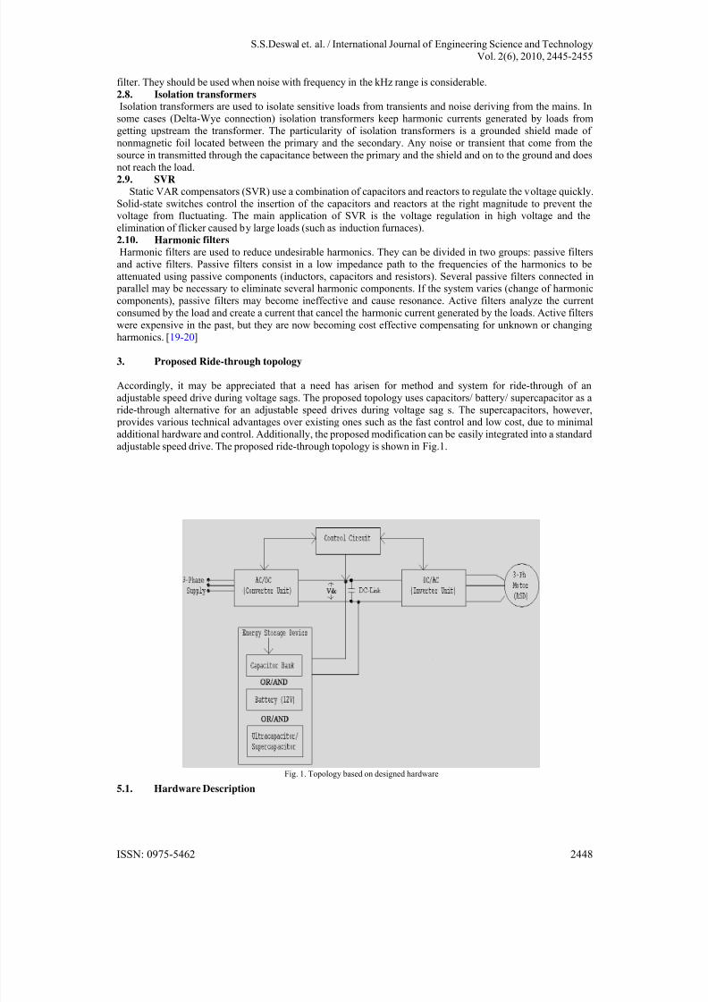
3. Proposed Ride-through topology
Accordingly, it may be appreciated that a need has arisen for method and system for ride-through of an
adjustable speed drive during voltage sags. The proposed topology uses capacitors/ battery/ supercapacitor as a
ride-through alternative for an adjustable speed drives during voltage sag s. The supercapacitors, however, provides various technical advantages over existing ones such as the fast control and low cost, due to minimal
additional hardware and control. Additionally, the proposed modification can be easily integrated into a standard
adjustable speed drive. The proposed ride-through topology is shown in Fig.1.
5.1. Hardware Description
Fig. 1. Topology based on designed hardware
ISSN: 0975-5462 2448
8/8/2019 Improved Performance of an Adjustable Speed Drives During Voltage Sag Condition
http://slidepdf.com/reader/full/improved-performance-of-an-adjustable-speed-drives-during-voltage-sag-condition 5/11
S.S.Deswal et. al. / International Journal of Engineering Science and Technology
Vol. 2(6), 2010, 2445-2455
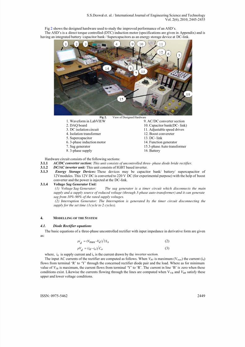
Fig 2 shows the designed hardware used to study the improved performance of an ASD’s.
The ASD’s is a direct torque controlled (DTC) induction motor (specifications are given in Appendix) and ishaving an integrated battery /capacitor bank / Supercapacitors as an energy storage device at DC-link.
Fig 2. View of Designed Hardware1. Waveform in LabVIEW 9. AC/DC converter section
2. DAQ board 10. Capacitor bank(DC- link)3. DC isolation circuit 11. Adjustable speed drives
4. Isolation transformer 12. Boost convereter
5. Supercapacitor 13. DC- link 6. 3-phase induction motor 14. Function generator
7. Sag generator 15.3-phase Auto transformer
8. 3-phase supply 16. Battery
Hardware circuit consists of the following sections:
3.1.1 AC/DC converter section: This unit consists of uncontrolled three- phase diode bride rectifier. 3.1.2 DC/AC inverter unit: This unit consists of IGBT based inverter.
3.1.3 Energy Storage Devices: These devices may be capacitor bank/ battery/ supercapacitor of
12Vmodules. This 12V DC is converted to 220 V DC (for experimental purpose) with the help of boostconverter and the power is injected at the DC-link.
3.1.4 Voltage Sag Generator Unit:
(1) Voltage Sag Generator: The sag generator is a timer circuit which disconnects the main
supply and a supply source of reduced voltage (through 3-phase auto-transformer) and it can generate
sag from 10%-90% of the rated supply voltages.
(2) Interruption Generator: The Interruption is generated by the timer circuit disconnecting the
supply for the set time (1cycle to 2 cycles).
4. MODELLING OF THE SYSTEM
4.1. Diode Rectifier equations
The basic equations of a three-phase uncontrolled rectifier with input impedance in derivative form are given
as:( ) 2max pi V V Ld sd
(2)
( ) pV i i C d o od (3)
where, id is supply current and io is the current drawn by the inverter section.
The input AC currents of the rectifier are computed as follows. When V RY is maximum (Vmax) the current (id)
flows from terminal ‘R’ to ‘Y’ through the concerned rectifier diode pair and the load. Where as for minimum
value of V YR is maximum, the current flows from terminal ‘Y’ to ‘R’. The current in line ‘B’ is zero when these
conditions exist. Likewise the currents flowing through the lines are computed when VYB and V BR satisfy these
upper and lower voltage conditions.
ISSN: 0975-5462 2449
8/8/2019 Improved Performance of an Adjustable Speed Drives During Voltage Sag Condition
http://slidepdf.com/reader/full/improved-performance-of-an-adjustable-speed-drives-during-voltage-sag-condition 6/11
S.S.Deswal et. al. / International Journal of Engineering Science and Technology
Vol. 2(6), 2010, 2445-2455
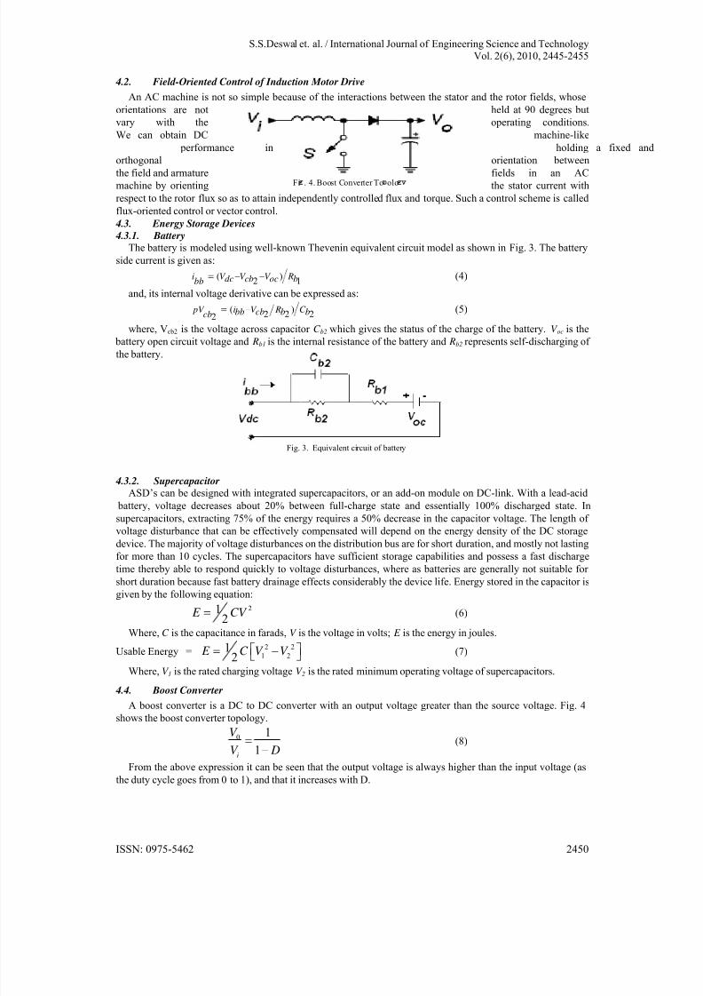
4.2. Field-Oriented Control of Induction Motor Drive
An AC machine is not so simple because of the interactions between the stator and the rotor fields, whose
orientations are not held at 90 degrees but
vary with the operating conditions.
We can obtain DC machine-like
performance in holding a fixed and
orthogonal orientation between
the field and armature fields in an ACmachine by orienting the stator current with
respect to the rotor flux so as to attain independently controlled flux and torque. Such a control scheme is called
flux-oriented control or vector control.
4.3. Energy Storage Devices
4.3.1. Battery
The battery is modeled using well-known Thevenin equivalent circuit model as shown in Fig. 3. The battery
side current is given as:
( )2 1
i V V V Rdc cb oc bbb (4)
and, its internal voltage derivative can be expressed as:
( )2 2 22
pV i V R C bb cb b bcb (5)
where, Vcb2 is the voltage across capacitor C b2 which gives the status of the charge of the battery. V oc is the
battery open circuit voltage and Rb1 is the internal resistance of the battery and Rb2 represents self-discharging of the battery.
4.3.2. Supercapacitor
ASD’s can be designed with integrated supercapacitors, or an add-on module on DC-link. With a lead-acid
battery, voltage decreases about 20% between full-charge state and essentially 100% discharged state. Insupercapacitors, extracting 75% of the energy requires a 50% decrease in the capacitor voltage. The length of
voltage disturbance that can be effectively compensated will depend on the energy density of the DC storage
device. The majority of voltage disturbances on the distribution bus are for short duration, and mostly not lasting
for more than 10 cycles. The supercapacitors have sufficient storage capabilities and possess a fast discharge
time thereby able to respond quickly to voltage disturbances, where as batteries are generally not suitable for
short duration because fast battery drainage effects considerably the device life. Energy stored in the capacitor is
given by the following equation:
212
E CV (6)
Where, C is the capacitance in farads, V is the voltage in volts; E is the energy in joules.
Usable Energy =2 2
1 21
2 E C V V (7)
Where, V 1 is the rated charging voltage V 2 is the rated minimum operating voltage of supercapacitors.
4.4. Boost Converter
A boost converter is a DC to DC converter with an output voltage greater than the source voltage. Fig. 4
shows the boost converter topology.
0 1
1i
V
V D
(8)
From the above expression it can be seen that the output voltage is always higher than the input voltage (as
the duty cycle goes from 0 to 1), and that it increases with D.
Fig. 3. Equivalent circuit of battery
Fi . 4. Boost Converter To olo
ISSN: 0975-5462 2450
8/8/2019 Improved Performance of an Adjustable Speed Drives During Voltage Sag Condition
http://slidepdf.com/reader/full/improved-performance-of-an-adjustable-speed-drives-during-voltage-sag-condition 7/11
S.S.Deswal et. al. / International Journal of Engineering Science and Technology
Vol. 2(6), 2010, 2445-2455
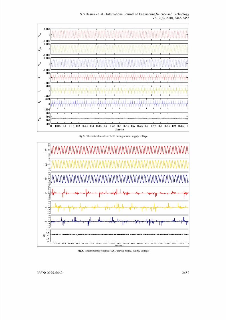
5. Experimental Results and Discussion
The objective of this section is to investigate the performance of an ASD under normal and voltage sagcondition.
Fig 7 to Fig 10 shows the performance of the proposed scheme.
The parameters Vry, Yyb, V br , Ir , Iy , I b and Vdc show the three- phase source voltages, line currents, and DC-link voltage respectively. The voltages and currents are also shown for different phases.
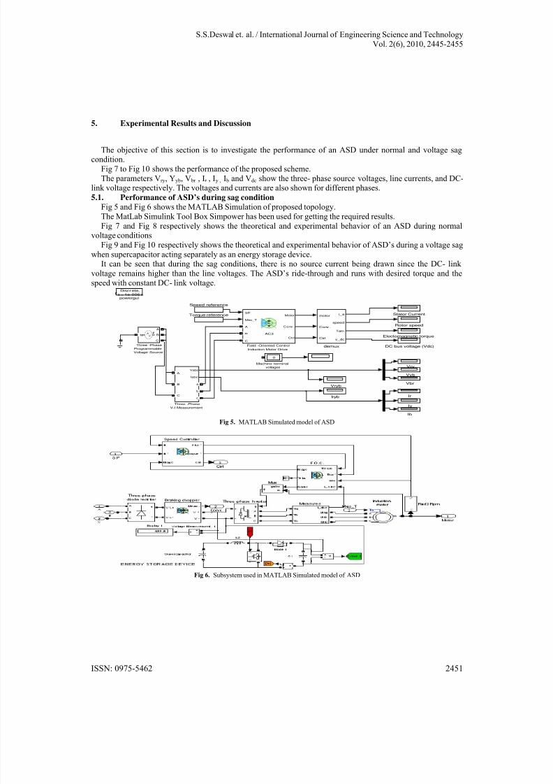
5.1. Performance of ASD’s during sag condition
Fig 5 and Fig 6 shows the MATLAB Simulation of proposed topology.
The MatLab Simulink Tool Box Simpower has been used for getting the required results.
Fig 7 and Fig 8 respectively shows the theoretical and experimental behavior of an ASD during normalvoltage conditions
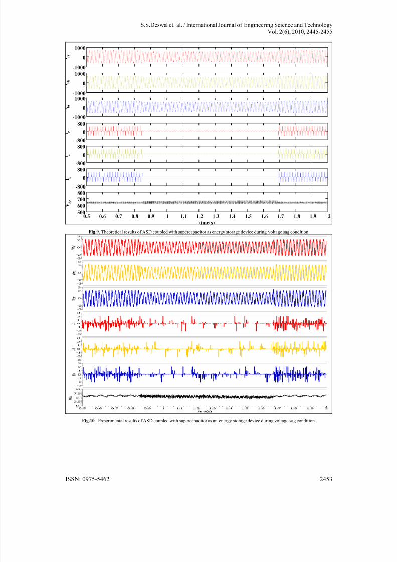
Fig 9 and Fig 10 respectively shows the theoretical and experimental behavior of ASD’s during a voltage sag
when supercapacitor acting separately as an energy storage device.
It can be seen that during the sag conditions, there is no source current being drawn since the DC- link voltage remains higher than the line voltages. The ASD’s ride-through and runs with desired torque and the
speed with constant DC- link voltage.
powergui
Discrete,
s = 1e-006 s
demux
motor
Conv .
Ctrl
i_a
speed
Tem
v_dc
Vyb
Vryb
Vry
Vbr
Torque reference
Three -Phase
V-I Measurement
Vabc
Iabc
A
B
C
a
b
c
Three -Phase
Programmable
Voltage Source
N
A
B
C
Stator Current
Speed reference
Rotor speed
Machine terminal
voltages
0
Iy
Iryb Ir
Ib
Field -Oriented Control
Induction Motor Drive
SP
Mec_T
Motor
Conv.
Ctrl
A
B
C
AC3Electomagnetic torque
DC bus voltage (Vdc)
Fig 5. MATLAB Simulated model of ASD
Fig 6. Subsystem used in MATLAB Simulated model of ASD
ISSN: 0975-5462 2451
8/8/2019 Improved Performance of an Adjustable Speed Drives During Voltage Sag Condition
http://slidepdf.com/reader/full/improved-performance-of-an-adjustable-speed-drives-during-voltage-sag-condition 8/11
S.S.Deswal et. al. / International Journal of Engineering Science and Technology
Vol. 2(6), 2010, 2445-2455
-1000
0
1000
V r y
-1000
0
1000
V y b
-1000
0
1000
V b r
-800
0
800
I r
-800
0
800
I y
-800
0
800 I b
0 0 .0 5 0 .1 0 .1 5 0 .2 0 .2 5 0 .3 0 .3 5 0 .4 0 .4 5 0 .5 0.5 5 0 .6 0 .6 5 0 .7 0 .7 5 0 .8 0 .8 5 0 .9 0 .9 5 1500
600
700
800
time(s)
V d c
Fig 7. Theoretical results of ASD during normal supply voltage
Fig.8. Experimental results of ASD during normal supply voltage
ISSN: 0975-5462 2452
8/8/2019 Improved Performance of an Adjustable Speed Drives During Voltage Sag Condition
http://slidepdf.com/reader/full/improved-performance-of-an-adjustable-speed-drives-during-voltage-sag-condition 9/11
S.S.Deswal et. al. / International Journal of Engineering Science and Technology
Vol. 2(6), 2010, 2445-2455
-1000
0
1000
r y
-1000
0
1000
y b
-1000
0
1000
b r
-800
0
800
r
-800
0
800
y
-800
0
800
I b
0.5 0.6 0.7 0.8 0.9 1 1.1 1.2 1.3 1.4 1.5 1.6 1.7 1.8 1.9 2500
600
700800
time(s)
V d c
Fig.9. Theoretical results of ASD coupled with supercapacitor as energy storage device during voltage sag condition
Fig.10. Experimental results of ASD coupled with supercapacitor as an energy storage device during voltage sag condition
ISSN: 0975-5462 2453

8/8/2019 Improved Performance of an Adjustable Speed Drives During Voltage Sag Condition
http://slidepdf.com/reader/full/improved-performance-of-an-adjustable-speed-drives-during-voltage-sag-condition 10/11
S.S.Deswal et. al. / International Journal of Engineering Science and Technology
Vol. 2(6), 2010, 2445-2455
6. Conclusions
From the discussion it is clear that Super-capacitors, due to high power density and low ESR, are a very
convenient energy storage component to be used in power quality applications. A proposed topology usingsupercapacitor as an energy storage device is developed and tested. The proposed topology is capable of
providing full ride-through to an ASD by maintaining the dc link voltage level constant during the duration of
the power quality disturbance i.e. voltage sag. The effectiveness of the proposed ride through topology is shown by means of simulations based on MATLAB and experimental results obtained on a laboratory prototype. From
these results it is clear that the supercapacitor’s dynamic response is fast enough to respond to the load transientrequirements and avoid the effects of the various power quality disturbances on the adjustable speed drive.
Appendix
Simulation Circuit:
Induction Motor rating and parameters:5 H.P, 415 volts(L-L), 3- Phase, 4 Poles, 50 Hz, 1444 rpm.
DC- link capacitor = 5 F,
DC- link voltage = 620 volts
Experimental Setup
Induction Motor rating and parameters:5 H.P, 415 V (L-L), 3-Phase, 4 Poles, 50 Hz,1444 rpm.
DC- link capacitor(supercapacitor) = 5 F / 13.5 V
DC- link voltage = 620 voltsLabView measurement scale
Source Voltage and Current : 1: 300
DC Link Voltage : 1:100
References
Periodicals:[1] M. H. J. Bolen, L.D. Zhang, “Analysis of Voltage Tolerance of AC Adjustable-Speed Drives for Three- Phase Balanced and
Unbalanced Sags”, IEEE Transactions on Industry Applications, Vol 36, no. 333, May/June 2000.
[2] Von Jouanne, P.N. Enjeti and B. Banerjee, “Assessment of Ride-Through Alternatives for Adjustable-Speed Drives”, IEEETransactions on Industry Applications, vol. 35, no. 4, July/ August 1999.
[3] S.S.Deswal, et.al, “Ride-Through Topology for Adjustable Speed Drives (ASD’s) During Power System Faults”, has been published in
International Journal of Computer Science, Informatics and Electrical Engineering (JCSIEE), vol.2, issue 1, 2008. pp.1– 11.[4] S.S.Deswal, et.al, “Application of Boost Converter For Ride-through Capability of Adjustable Speed Drives during Sag and Swell
Conditions”, has been published in International Journal of Electrical and Electronics Engineering (IJEEE), vol.4, issue 3, 2009(pp-
184-188)
[5] S.S.Deswal, et.al, “Analysis of Ride-through Topology for Adjustable Speed Drives duringabnormal fault Conditions”, has been published in Journal of Electrical Engineering (JEE), vol -9, Edition-:1,2009. pp.1- 8.
[6] M.H.J. Bollen, “Characterization of voltage dips experienced by three-phase adjustable-speed drives,” IEEE Transactions on Power Delivery, Vol. PD-12, no.4, October 1997, pp.1666-1671.
Books:[7] M. H. J. Bollen, “Understanding Power Quality Problems: Voltage Sags and Interruptions”, IEEE Press, New York, 1999.[8] G.T. Heydt, Electric Power Quality, 2nd ed. WestLafayette, Stars in a Circle, 1994.
Papers from Conference Proceedings (Published):[9] A. Von, P.N. Enjeti, B. Banerjee, “Assessment of Ride-Through Alternatives for Adjustable-Speed Drives”, IEEE Trans. on Industry
Application vol. 35, issue 4, pp. 908 - 916, July-Aug. 1999.
[10] K. Stockman, F. D’hulster, M. Didden, R. Belmans. “Embedded Solutions to Protect Textile Processes against Voltage Sags”. 37thAnnual Meeting of the Industry Applications Conference. Vol.4, 13-18 Oct. 2002. pp. 2561 – 2566.
[11] I. C. de Albuquerque, R.P.S. Leão, “Evaluating ASD Performance under Short Duration Voltage Variation”, IEEE Transmission &
Distribution Conference, IEEE/PES T&D 2002 Latin America, São Paulo, 2002. v.1. pp.1– 6.
[12] A. van Zyl, R. Spée, “Short Term Energy Storage for ASD Ride-Through”, Industry Applications Conference, 1998, Thirty-Third IASAnnual Meeting, Volume 2, Issue, 12-15 Oct 1998 pp:1162-1167 vol.2A.
[13] F. D. Silva, A. J. J. Rezek, A. A. P Junior, L. E. B. D. Silva, P. C. Rosa, and L. O. M. Reis, “Ultracapacitor-Based Ride-Through
System for Adjustable Speed Drives Applied to Critical Process”, IEEE conference on Harmonics and Quality of Power, vol. 2, pp.632-638, 2002.
[14] Y.R.L. Jayawickrama and S. Rajakaruna, “Ultracapacitor Based Ride-Through System for a DC Load”, IEEE Conference on Power System Technology, vol. 1, pp. 232-237, 2004.
[15] S.Dahiya. D.K.Jain. Ashok Kumar, R.Dahiya, S.S.Deswal, “Ride-through Capabilities of ASD’s Using Supercapacitors”, Proceedings
of 8th International Power Engineering Conference (IPEC-07), pp-714-719, Singapore, 2007.
Standards:[16] IEC61000-4-34 “Electromagnetic compatibility (EMC) - Part 4-34: Testing and measurement techniques-Voltage dips, short
interruptions and voltage variations immunity tests for equipment with input current more than 16 A per phase”, July 2004.
[17] IEC 61000-4-11, Ed.2, Voltage dips, short interruptions and voltage variations immunity tests, March 2004.
[18] SEMI F-47-0706, Specification for semiconductor processing equipment voltage sag immunity.
[19] IEEE Recommended Practices on Monitoring Electric Power Quality, IEEE Std.1159, 1995.
ISSN: 0975-5462 2454

8/8/2019 Improved Performance of an Adjustable Speed Drives During Voltage Sag Condition
http://slidepdf.com/reader/full/improved-performance-of-an-adjustable-speed-drives-during-voltage-sag-condition 11/11
S.S.Deswal et. al. / International Journal of Engineering Science and Technology
Vol. 2(6), 2010, 2445-2455
[20] IEEE Recommended Practices for Evaluating Electric Power System Compatibility With Electronic Process Equipment, IEEEStd.1346, 1998.
ISSN: 0975 5462 2455