impact of lead free simulated repeated reflow on through … · impact of lead free simulated...
TRANSCRIPT

Impact of lead free simulated repeated reflow on through hole reliability using AATC
Multek
+49 171 463 5431
February 07, 2006
ABRACI
Sao Paulo

As of July 1, 2006, use of the following
substances in electrical and electronics
equipment sold in the EU is banned:
�Lead (Pb)
�Cadmium (Cd)
�Hexavalent Chromium (Cr+6)
�Mercury (Hg)�Poly Brominated Biphenyls (PBB)�Poly Brominated Di-Phenyl Ether (PBDE)
RoHS Directive 2002/95/EC January 27 2003
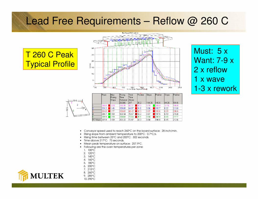
Lead Free Requirements – Reflow @ 260 C
• Conveyor speed used to reach 260°C on the board surface: 28 inch/min.
• Rising slope from ambient temperature to 200°C: 0.7°C/s.
• Rising time between 25°C and 200°C: 302 seconds.
• Time above 217°C: 73 seconds.
• Mean peak temperature on surface: 257.9°C.
• Following are the oven temperatures per zone:
1. 100°C
2. 120°C
3. 140°C
4. 160°C
5. 180°C
6. 200°C
7. 215°C
8. 260°C
9. 285°C 10. 290°C
T 260 C PeakTypical Profile
Must: 5 xWant: 7-9 x2 x reflow1 x wave1-3 x rework

High Temperature Solder Reflow
Unknowns
�Via reliability (via cracking)?
�De-Lamination Resistance ?
�De Composition Resistance?
�Electrical Degradation?
�Other potential latent defects??

Typical Lead Free Assembly Requirements
Significant more stress on
the PCB during PCB
assembly and repair
(potentially multiple times)

Study objective
Objectives:
� Understand the impact of simulated lead free repeated reflow on through hole reliability and its failure modes and understand the importance of the material properties
� CTE
� Tg
� Curing mechanism
� Verify test methodology with “small” number of materials to discriminate materials for LF suitability

Project Scope
Variables
Materials:
� Isola FR 402
�Polyclad PCL 254
� Isola IS 400
� Isola IS 410
Process:
�Simulated Lead Free Repeated Reflow (Convection Reflow Oven)
� 2, 4, 5, 6 times at 250 C conditioning before thermal cycling
Measured Response
�Decrease in Through Hole Life Expectation (probability plots)

Test Vehicle / Test Procedure
120 mil (3.2 mm) thick (8 samples / condition min)12 mil (0.3 mm) drill diameter 10 : 1 Aspect Ratio8 layers880 Plated Through Holes (PTH)Target copper metallization (0.8 mil = 20 µm thickness) No finishBase Laminates:
�Isola FR402 (low Tg, dicy cured and unfilled)�Polyclad PCL-FR-254 (mid-Tg, Dicy cured and filled)�Isola IS400 (mid-Tg, Phenolic cured and filled resin)�Isola IS410 (high-Tg, Phenolic cured and unfilled)
Test Conditions:�5 min @ -55°C�14 min transition time�5 min @ 125°C�14 min transition time
Failure criterion: 10% resistance increase of the initial value

Tested Materials
340
13 / 16
> 10 s
n/a
45
280
155
PCL 254
Dicy Cured
300
14 / 17
>10 s
2
52
321
130 - 135
FR 402
Dicy Cured
340 - 360340 - 360Td (C)
17 / 15 (fill)
13 / 6 (warp)
15 / 12 (fill)
12 / 5 (warp)
x/y( PPM)
expansion
30 min10 minT288 (min)
6060 T260 (min)
55
217
38
200
Z – axis <Tg
PPM >Tg
170 – 180145 - 150Tg (C)
IS 410
Phenolic C.
IS 400
Phenolic C.
Material
Properties
Filled Filled
Influence of Reflow Temperature on
PTH Reliability
224 C Peak vs. 250 C Peak for 5 simulated cycles
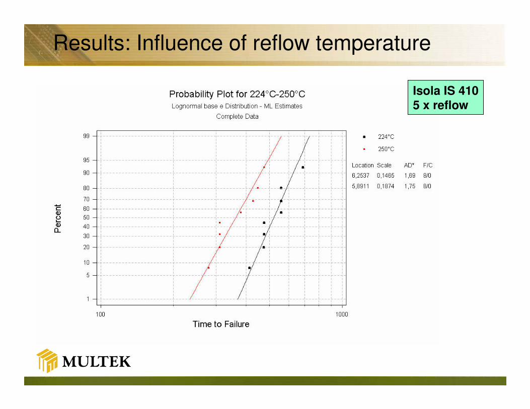
Results: Influence of reflow temperature
Isola IS 410
5 x reflow

Isola IS 400
5 x reflow
Results: Influence of reflow temperature

Polyclad PCL-
FR 254
5 x reflow
Results: Influence of reflow temperature

All tested materials
5 x reflow
An increase of 25°C
in reflow temperature simulated 5 x
reduces reliability by about 25 %
Results: Influence of reflow temperature
Influence of number of simulated reflow
cycles on PTH reliability
224 C Peak vs. 250 C Peak
2 , 4, 5, 6 simulated reflow cycles

IS 410
250°C reflow
Results: Influence of number of reflow cycles
2456

All tested materials
224°C reflow
Results: Influence of number of reflow cycles
Increasing numberof reflow cycles reduce the through-
hole reliability, more at higher temperatures.
2456

All materialstested250°C reflow
Increasing numberof reflow cycles reduces the through-hole reliability. More
at higher temperatures
Results: Influence of number of reflow cycles
2456

Influence of laminate type on PTH
reliability
224 C Peak vs. 250 C Peak
2 and 6 simulated reflow cycles
IS 410, IS 400, PCL 254

2 x reflow
224°C and 250°C peak temp.
Results: Influence of base material
IS 400
IS 410
PCL 254

6 x reflow,
224°C and 250°C peak temp.
Results: Influence of base material
IS 400
IS 410
PCL 254

All pre-conditioning TBoth peak T
IS 400 (mid Tg, phenolic
cured, filled) shows thebest through hole reliabilityof the investigated materials.
Results: Influence of base material
IS 400
IS 410
PCL 254

Comparison Dicy Curing vs. Phenolic Curing
5x reflow
224 and 250°C
peak temp.
STD
MNF1
HN
MNF2
5x reflow
224 and 250°C
peak temp.
FR 402
PCL 254
IS 410
IS 400
Dicy Cured Phenolic Cured

Material Properties (measured)
Tg, TMACTE (z)
below Tg
CTE (z)
above Tg
°C ppm/K ppm/K 20 - 250°C
FR 402 130 - 135 67 321 44240
P- 254 150 - 155 67 315 40210
IS 400 145 - 150 57 293 37890IS 410 170 - 180 73 285 33750
Lowest CTE valueHighest CTE value
z-axis-expansion
ppm
Comment
Dicy Cured
Dicy Cured Filled
PC - Filled
Phenolic Cured

FAILURE ANALYSIS
BARREL CRACKS
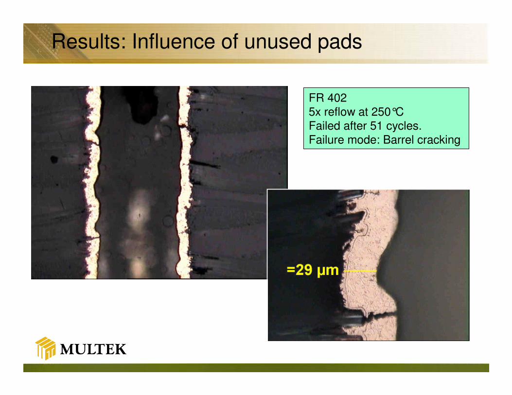
FR 402 5x reflow at 250°CFailed after 51 cycles.Failure mode: Barrel cracking
Results: Influence of unused pads
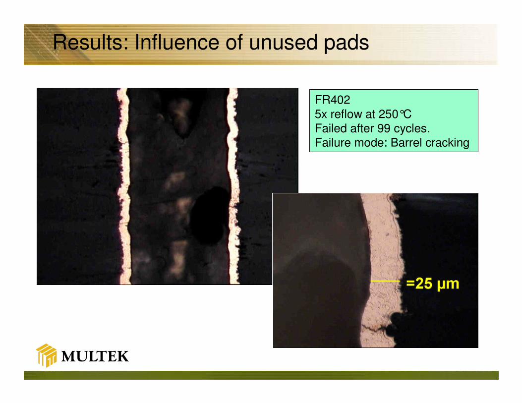
FR4025x reflow at 250°CFailed after 99 cycles.Failure mode: Barrel cracking
Results: Influence of unused pads

IS4006 x reflow 250°C peak TFailed after 1096 cycles
Failure mode: Barrel cracking
Results: Failure Modes
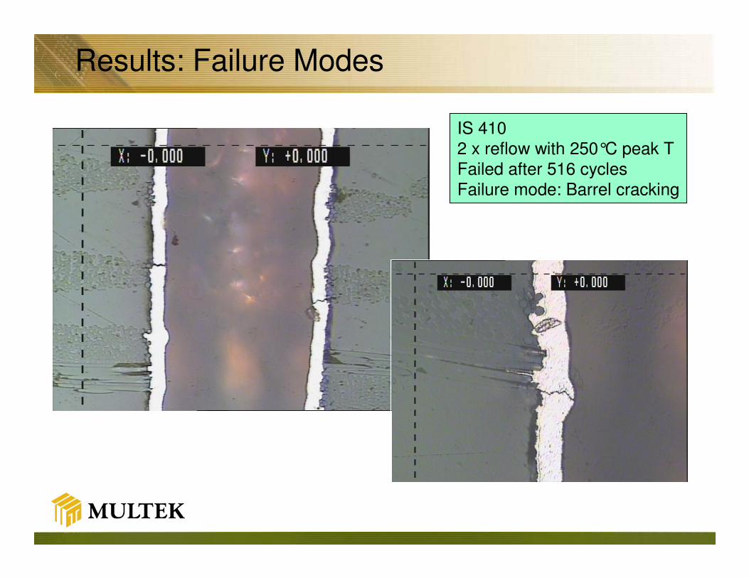
IS 4102 x reflow with 250°C peak TFailed after 516 cycles Failure mode: Barrel cracking
Results: Failure Modes

PCL 254After 2 x reflow 250°C peak TFailed after 478 cycles Failure mode: Barrel cracking
Results: Failure Modes

AATC - Summary
�An increase of ~ 25°C in reflow temperature decreases through hole reliability roughly by about 25%.(at 5 x reflow)
�Increasing number of reflow cycles reduces the through hole reliability.
�Material ranking IS 400 �IS 410 � PCL 254 � FR 402�Phenolic Filled, Phenolic, Dicy Filled, Dicy
�Tg is NOT the most critical factor for reliability & Lead Free Material Selection�Low z axes expansion (filled materials) can serve efficiently
�Predominant failure mode observed has been barrel cracking (what we want to see)
�AATC tests have been suitable for further material benchmarking and ranking (although time consuming)
�Plan is to test further materials against the tested 4