impact of carbon fibre epoxy corrugated cores
DESCRIPTION
Impact of carbon fibre epoxy corrugated cores - composite structuresTRANSCRIPT
Composite Structures 94 (2012) 3300–3308
Contents lists available at SciVerse ScienceDirect
Composite Structures
journal homepage: www.elsevier .com/locate /compstruct
Impact of carbon fibre/epoxy corrugated cores
S. Kazemahvazi a, B.P. Russell b,⇑, D. Zenkert a
a Department of Aeronautical and Vehicle Engineering, KTH, Teknikringen 8, Stockholm 100 44, Swedenb Engineering Department, University of Cambridge, Trumpington Street, Cambridge CB1 1PZ, UK
a r t i c l e i n f o a b s t r a c t
Article history:Available online 22 May 2012
Keywords:Corrugated coresSandwich structuresBlast protectionInertial stabilisation
0263-8223/$ - see front matter � 2012 Elsevier Ltd. Ahttp://dx.doi.org/10.1016/j.compstruct.2012.04.034
⇑ Corresponding author.E-mail address: [email protected] (B.P. Russell).
The dynamic compressive response of corrugated carbon-fibre reinforced epoxy sandwich cores has beeninvestigated using a Kolsky-bar set-up. Compression at quasi-static rates up to v0 = 200 ms�1 have beentested on three different slenderness ratios of strut. High speed photography was used to capture the fail-ure mechanisms and relate these to the measured axial compressive stress. Experiments show significantstrength enhancement as the loading rate increases. Although material rate sensitivity accounts for someof this, it has been shown that the majority of the strength enhancement is due to inertial stabilisation ofthe core members. Inertial strength enhancement rises non-linearly with impact velocity. The largestgains are associated with a shift to buckle modes composed of 2–3 half sine waves. The loading ratestested within this study are similar to those that are expected when a sandwich core is compresseddue to a blast event.
� 2012 Elsevier Ltd. All rights reserved.
1. Introduction
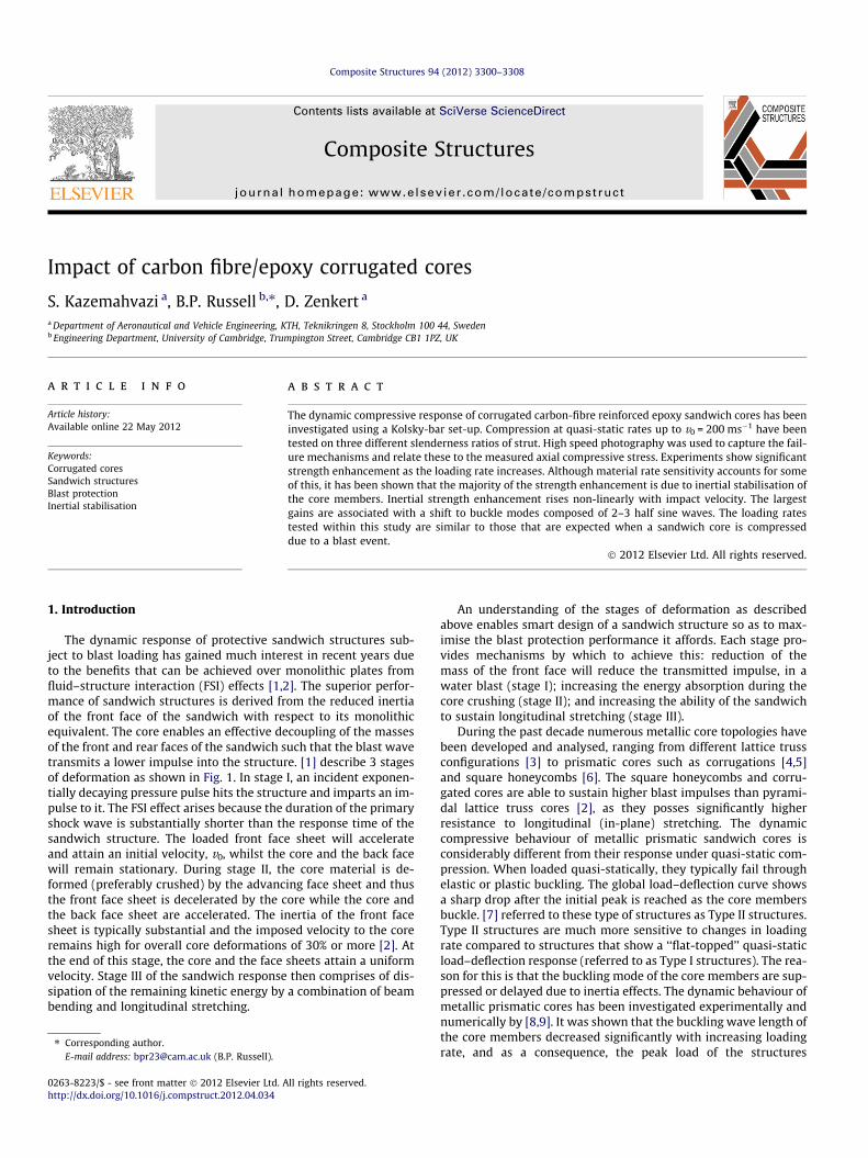
The dynamic response of protective sandwich structures sub-ject to blast loading has gained much interest in recent years dueto the benefits that can be achieved over monolithic plates fromfluid–structure interaction (FSI) effects [1,2]. The superior perfor-mance of sandwich structures is derived from the reduced inertiaof the front face of the sandwich with respect to its monolithicequivalent. The core enables an effective decoupling of the massesof the front and rear faces of the sandwich such that the blast wavetransmits a lower impulse into the structure. [1] describe 3 stagesof deformation as shown in Fig. 1. In stage I, an incident exponen-tially decaying pressure pulse hits the structure and imparts an im-pulse to it. The FSI effect arises because the duration of the primaryshock wave is substantially shorter than the response time of thesandwich structure. The loaded front face sheet will accelerateand attain an initial velocity, v0, whilst the core and the back facewill remain stationary. During stage II, the core material is de-formed (preferably crushed) by the advancing face sheet and thusthe front face sheet is decelerated by the core while the core andthe back face sheet are accelerated. The inertia of the front facesheet is typically substantial and the imposed velocity to the coreremains high for overall core deformations of 30% or more [2]. Atthe end of this stage, the core and the face sheets attain a uniformvelocity. Stage III of the sandwich response then comprises of dis-sipation of the remaining kinetic energy by a combination of beambending and longitudinal stretching.
ll rights reserved.
An understanding of the stages of deformation as describedabove enables smart design of a sandwich structure so as to max-imise the blast protection performance it affords. Each stage pro-vides mechanisms by which to achieve this: reduction of themass of the front face will reduce the transmitted impulse, in awater blast (stage I); increasing the energy absorption during thecore crushing (stage II); and increasing the ability of the sandwichto sustain longitudinal stretching (stage III).
During the past decade numerous metallic core topologies havebeen developed and analysed, ranging from different lattice trussconfigurations [3] to prismatic cores such as corrugations [4,5]and square honeycombs [6]. The square honeycombs and corru-gated cores are able to sustain higher blast impulses than pyrami-dal lattice truss cores [2], as they posses significantly higherresistance to longitudinal (in-plane) stretching. The dynamiccompressive behaviour of metallic prismatic sandwich cores isconsiderably different from their response under quasi-static com-pression. When loaded quasi-statically, they typically fail throughelastic or plastic buckling. The global load–deflection curve showsa sharp drop after the initial peak is reached as the core membersbuckle. [7] referred to these type of structures as Type II structures.Type II structures are much more sensitive to changes in loadingrate compared to structures that show a ‘‘flat-topped’’ quasi-staticload–deflection response (referred to as Type I structures). The rea-son for this is that the buckling mode of the core members are sup-pressed or delayed due to inertia effects. The dynamic behaviour ofmetallic prismatic cores has been investigated experimentally andnumerically by [8,9]. It was shown that the buckling wave length ofthe core members decreased significantly with increasing loadingrate, and as a consequence, the peak load of the structures
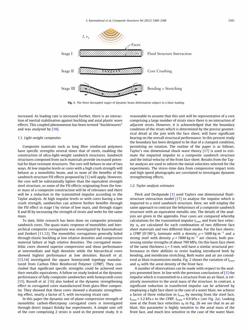
Fig. 1. The three decoupled stages of dynamic beam deformation subject to a blast loading.
S. Kazemahvazi et al. / Composite Structures 94 (2012) 3300–3308 3301
increased. As loading rate is increased further, there is an interac-tion of inertial stabilisation against buckling and axial plastic waveeffects. This coupled phenomenon has been termed ‘‘bucklewaves’’and was analysed by [10].
1.1. Light-weight composites
Composite materials such as long fibre reinforced polymershave specific strengths several times that of steels, enabling theconstruction of ultra-light-weight sandwich structures. Sandwichstructures composed from such materials provide increased poten-tial for blast resistant structures. The core will behave in one of twoways. At low impulse levels or cores with a high crush strength willbehave as a monolithic beam, and so none of the benefits of thesandwich structure FSI effects proposed by [1] will apply. However,the core will be substantially lighter than the equivalent strengthsteel structure, so some of the FSI effects originating from the low-er mass of a composite construction will be of relevance and therewill be a reduction in the transmitted impulse according to theTaylor analysis. At high impulse levels or with cores having a lowcrush strength, sandwiches can achieve further benefits throughthe FSI effect in stage I by virtue of low mass, and through stagesII and III by increasing the strength of struts and webs for the samemass.
To date, little research has been done on composite prismaticsandwich cores. The quasi-static response of monolithic and hier-archical composite corrugations was investigated by Kazemahvaziand Zenkert [11,12], The monolithic corrugations generally failedthrough elastic buckling at low relative densities and compressivematerial failure at high relative densities. The corrugated mono-lithic cores showed superior compressive and shear performanceat intermediate and high densities while the hierarchical coresshowed highest performance at low densities. Russell et al.[13,14] investigated the square honeycomb topology manufac-tured from Carbon Fibre Reinforced Polymer (CFRP). They con-cluded that significant specific strengths could be achieved overtheir metallic equivalents. A follow on study looked at the dynamicperformance of fully composite sandwiches with honeycomb cores[15]. Russell et al. [16] also looked at the dynamic strengtheningeffect in corrugated cores manufactured from glass-fibre compos-ite. They showed that these cores showed a dramatic strengthen-ing effect, nearly a factor of 5, with increasing strain rate.
In this paper the dynamic out-of-plane compressive strength ofmonolithic carbon-fibre/epoxy corrugated cores is investigatedthrough direct impact Kolsky bar experiments. A simple unit cellof the core comprising 2 struts is used in the present study. It is
reasonable to assume that this unit will be representative of a corecomprising a large number of struts since there is no interaction ofadjacent struts. However, it is acknowledged that the boundarycondition of the struts which is determined by the precise geomet-rical detail at the join with the face sheet, will have significantbearing on the overall structural performance. In this present studythe boundary has been designed to be that of a clamped condition,permitting no rotation. The outline of the paper is as follows.Taylor’s one dimensional shock wave theory [17] is used to esti-mate the imparted impulse to a composite sandwich structureand the initial velocity of the front face sheet. Results from the Tay-lor analysis are used to inform the initial velocities selected for theexperiments. The stress-time data from compressive impact testsand high speed photographs are correlated to investigate dynamicstrengthening effects.
1.2. Taylor analysis estimates
Fleck and Deshpande [1] used Taylors one dimensional fluid–structure interaction model [17] to analyse the impulse which isimparted to a steel sandwich structure. Here, we will employ thesame approach to contrast the behaviours of a composite sandwichstructure with an equivalent metallic one. The details of the anal-ysis are given in the appendix. Four cases are compared wherebycalculations for the transmitted impulse Itrans and front face veloc-ity v0 are calculated for each combination of two different facesheet materials and two different blast media. For the face sheets:a CFRP [0�/90�]X laminate with a density q = 1600 kg m�3 and astrong steel with density q = 7800 kg m�3 are chosen, both pos-sessing similar strengths of about 700 MPa. On this basis face sheetof the same thickness tf = 5 mm, will have a similar structural per-formance in their abilities to resist loading introduced both bybending, and membrane stretching. Both water and air are consid-ered as blast transmission media. Fig. 2 shows the variation of Itrans
and v0 with the areal density of the front face.A number of observations can be made with respect to the anal-
ysis presented here. In line with the previous conclusions of [1] theimpulse which is transmitted to a structure from an air blast, is rel-atively insensitive to the areal mass of the structure. In contrast, asignificant reduction in transferred impulse can be achieved byemploying a light face sheet in the case of a water blast, we achievea factor of three reduction in Itrans by moving from the steel face,Itrans = 3.2 kPa s to the CFRP, Itrans = 0.9 kPa s (see Fig. 2a). Lookingnow at the front face velocities v0 in Fig. 2b we see that in an airblast, this parameter is highly sensitive to the areal mass of thefront face, and much less sensitive in the case of the water blast.

(a) (b)
Fig. 2. The sensitivity of (a) the transmitted impulse Itrans and (b) the front face velocity v0 to the areal density of the front face. Two different face sheet materials are locatedon the plots for two different shock media. The analysis assumes a 1 kg TNT charge placed 1 m away from the structure.
Table 1Geometry of the corrugated unit cells.
Core type t/l t (mm) h (mm) x q (kg m�3)
Slender 0.015 0.52 33 70� 83Intermediate 0.030 1.04 33 70� 166Stubby 0.060 2.08 33 70� 333
3302 S. Kazemahvazi et al. / Composite Structures 94 (2012) 3300–3308
Compare the values for air: v0 = 240 ms�1 and 50 ms�1 for the CFRPand steel respectively, giving a difference of 190 ms�1. For thewater blast this difference is only 30 ms�1. Thus from a blast mit-igation perspective, the use of composites in the hull of a naval ves-sel can have significant benefits for reducing the transmittedimpulse. Whereas employing steel for elements of the superstruc-ture results in benefits from the lowering of the front face velocity.Of course, other considerations such as the position of the centre ofgravity of a ship need to be balanced with blast protection.
This analysis clearly sets forth the motivation for the presentstudy, and provides an indication for the relevant values of v0 fromwhich to assess a composite core.
2. Materials and experimental set up
2.1. Fabrication procedure
Inclined struts fabricated from carbon-fibre/epoxy unidirec-tional material were manufactured as follows (see Fig. 3). Unidirec-tional pre-preg of fibre type T700 embedded in an epoxy SE 84LV(manufactured by Gurit) were laid up and cured to give threethicknesses t = 0.5, 1 and 2 mm, see Table 1. The sheets were milledinto rectangles of height H = 35 mm and with W = 60 mm ensuringa high degree of parallelism (±60 lm). Face sheets were made from2024 Aluminium Alloy. Inclined groves were cut into the facesheets in order to give an accurate and repeatable angle of inclina-tion of x = 70�. Metal shim was used to pack the excess space be-tween the composite strut and the slot, and an epoxy adhesive(Araldite 2015) was used to fix the assembly. A scaffold was used
(a) (b)
Fig. 3. Geometry of the inc
during the gluing procedure to ensure all specimens were alignedappropriately and conformed to the desired geometry, Fig. 3. Thismethod of fixing the composite struts into the face sheets alsogives a high degree of rotational rigidity to the joint.
Material test coupons were also fabricated in order to investi-gate the material strain rate response, Fig. 4. A sandwich configu-ration was used so to avoid a global buckling failure mode.Divinycell H250 foam core of thickness c = 15 mm was bonded tothe composite sheets of thickness tm = 0.52 mm using Araldite420 adhesive. To prevent edge failure modes such as brooming,the specimens were tabbed at each end using CFRP. The resultantgauge length lg of these specimens was 10 mm, the full length lmbeing 30 mm.
2.2. Quasi-static experimental set-up
Quasi-static axial compression of inclined strut specimens andthe material sandwich coupons were performed in a screw-drivenuniaxial loading machine (Instron 5584) at a strain rate_e ¼ 10�3 s�1. Load was recorded with either a 100 kN or a 30 kNload cell depending on the expected failure load of the unit cell.
(c)
lined strut specimen.
(a) (b) (c)
Fig. 4. Fabrication and geometry of materials test coupon.
(a)
(b)
Fig. 5. Dynamic experimental set up.
S. Kazemahvazi et al. / Composite Structures 94 (2012) 3300–3308 3303
The axial compression displacement of the unit cell was measuredusing a linear voltage displacement extensometer that wasmounted between the rigid steel compression platens.
2.3. Dynamic experimental set-up
The dynamic compressive strength of the inclined struts, andthe material test coupons, were measured by use of an instru-mented Kolsky bar [18]. Specimens were mounted on the end ofthe Kolsky bar and impacted with a striking bar of the same diam-eter, D launched from a gas gun, Fig. 5. The forces on the rear of thespecimens are measured by inferring the stress in the Kolsky barthrough strain gauges, mounted 10D from the end of the bar. Straingauges with a length of 1 mm, were mounted in a half-Wheatstonebridge configuration. Input voltage was supplied through a strainbridge amplifier with a cut-off frequency of 500 kHz, and the
(a) (
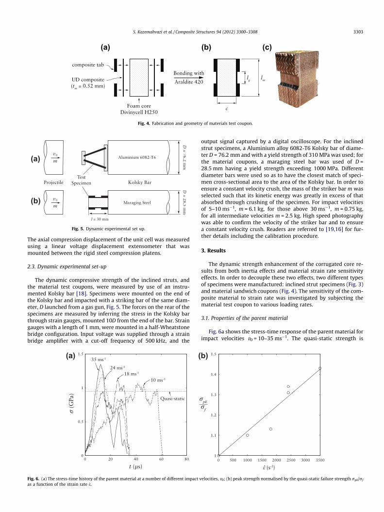
Fig. 6. (a) The stress-time history of the parent material at a number of different impact vas a function of the strain rate _e.
output signal captured by a digital oscilloscope. For the inclinedstrut specimens, a Aluminium alloy 6082-T6 Kolsky bar of diame-ter D = 76.2 mm and with a yield strength of 310 MPa was used; forthe material coupons, a maraging steel bar was used of D =28.5 mm having a yield strength exceeding 1000 MPa. Differentdiameter bars were used so as to have the closest match of speci-men cross-sectional area to the area of the Kolsky bar. In order toensure a constant velocity crush, the mass of the striker bar m wasselected such that its kinetic energy was greatly in excess of thatabsorbed through crushing of the specimen. For impact velocitiesof 5–10 ms�1, m = 6.1 kg, for those above 30 ms�1, m = 0.75 kg,for all intermediate velocities m = 2.5 kg. High speed photographywas able to confirm the velocity of the striker bar and to ensurea constant velocity crush. Readers are referred to [19,16] for fur-ther details including the calibration procedure.
3. Results
The dynamic strength enhancement of the corrugated core re-sults from both inertia effects and material strain rate sensitivityeffects. In order to decouple these two effects, two different typesof specimens were manufactured: inclined strut specimens (Fig. 3)and material sandwich coupons (Fig. 4). The sensitivity of the com-posite material to strain rate was investigated by subjecting thematerial test coupon to various loading rates.
3.1. Properties of the parent material
Fig. 6a shows the stress-time response of the parent material forimpact velocities v0 = 10–35 ms�1. The quasi-static strength is
b)
elocities, v0; (b) peak strength normalised by the quasi-static failure strength rpk/rf
(a) (b)
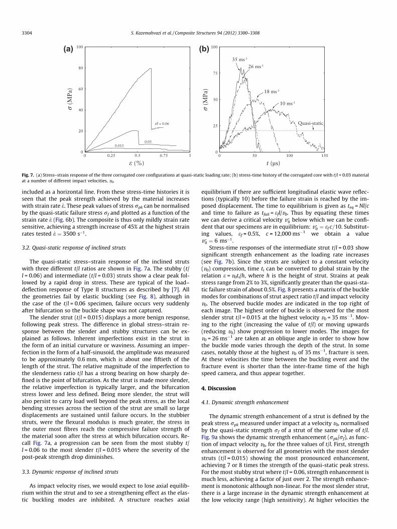
Fig. 7. (a) Stress–strain response of the three corrugated core configurations at quasi-static loading rate; (b) stress-time history of the corrugated core with t/l = 0.03 materialat a number of different impact velocities, v0.
3304 S. Kazemahvazi et al. / Composite Structures 94 (2012) 3300–3308
included as a horizontal line. From these stress-time histories it isseen that the peak strength achieved by the material increaseswith strain rate _e. These peak values of stress rpk can be normalisedby the quasi-static failure stress rf and plotted as a function of thestrain rate _e (Fig. 6b). The composite is thus only mildly strain ratesensitive, achieving a strength increase of 45% at the highest strainrates tested _e ¼ 3500 s�1.
3.2. Quasi-static response of inclined struts
The quasi-static stress–strain response of the inclined strutswith three different t/l ratios are shown in Fig. 7a. The stubby (t/l = 0.06) and intermediate (t/l = 0.03) struts show a clear peak fol-lowed by a rapid drop in stress. These are typical of the load–deflection response of Type II structures as described by [7]. Allthe geometries fail by elastic buckling (see Fig. 8), although inthe case of the t/l = 0.06 specimen, failure occurs very suddenlyafter bifurcation so the buckle shape was not captured.
The slender strut (t/l = 0.015) displays a more benign response,following peak stress. The difference in global stress–strain re-sponse between the slender and stubby structures can be ex-plained as follows. Inherent imperfections exist in the strut inthe form of an initial curvature or waviness. Assuming an imper-fection in the form of a half-sinusoid, the amplitude was measuredto be approximately 0.6 mm, which is about one fiftieth of thelength of the strut. The relative magnitude of the imperfection tothe slenderness ratio t/l has a strong bearing on how sharply de-fined is the point of bifurcation. As the strut is made more slender,the relative imperfection is typically larger, and the bifurcationstress lower and less defined. Being more slender, the strut willalso persist to carry load well beyond the peak stress, as the localbending stresses across the section of the strut are small so largedisplacements are sustained until failure occurs. In the stubbierstruts, were the flexural modulus is much greater, the stress inthe outer most fibres reach the compressive failure strength ofthe material soon after the stress at which bifurcation occurs. Re-call Fig. 7a, a progression can be seen from the most stubby t/l = 0.06 to the most slender t/l = 0.015 where the severity of thepost-peak strength drop diminishes.
3.3. Dynamic response of inclined struts
As impact velocity rises, we would expect to lose axial equilib-rium within the strut and to see a strengthening effect as the elas-tic buckling modes are inhibited. A structure reaches axial
equilibrium if there are sufficient longitudinal elastic wave reflec-tions (typically 10) before the failure strain is reached by the im-posed displacement. The time to equilibrium is given as teq = Nl/cand time to failure as tfail = efl/v0. Thus by equating these timeswe can derive a critical velocity v�0 below which we can be confi-dent that our specimens are in equilibrium: v�0 ¼ ef c=10. Substitut-ing values, ef = 0.5%, c = 12,000 ms�1 we obtain a valuev�0 ¼ 6 ms�1.
Stress-time responses of the intermediate strut t/l = 0.03 showsignificant strength enhancement as the loading rate increases(see Fig. 7b). Since the struts are subject to a constant velocity(v0) compression, time ti can be converted to global strain by therelation e = v0ti/h, where h is the height of strut. Strains at peakstress range from 2% to 3%, significantly greater than the quasi-sta-tic failure strain of about 0.5%. Fig. 8 presents a matrix of the bucklemodes for combinations of strut aspect ratio t/l and impact velocityv0. The observed buckle modes are indicated in the top right ofeach image. The highest order of buckle is observed for the mostslender strut t/l = 0.015 at the highest velocity v0 = 35 ms�1. Mov-ing to the right (increasing the value of t/l) or moving upwards(reducing v0) show progression to lower modes. The images forv0 = 26 ms�1 are taken at an oblique angle in order to show howthe buckle mode varies through the depth of the strut. In somecases, notably those at the highest v0 of 35 ms�1, fracture is seen.At these velocities the time between the buckling event and thefracture event is shorter than the inter-frame time of the highspeed camera, and thus appear together.
4. Discussion
4.1. Dynamic strength enhancement
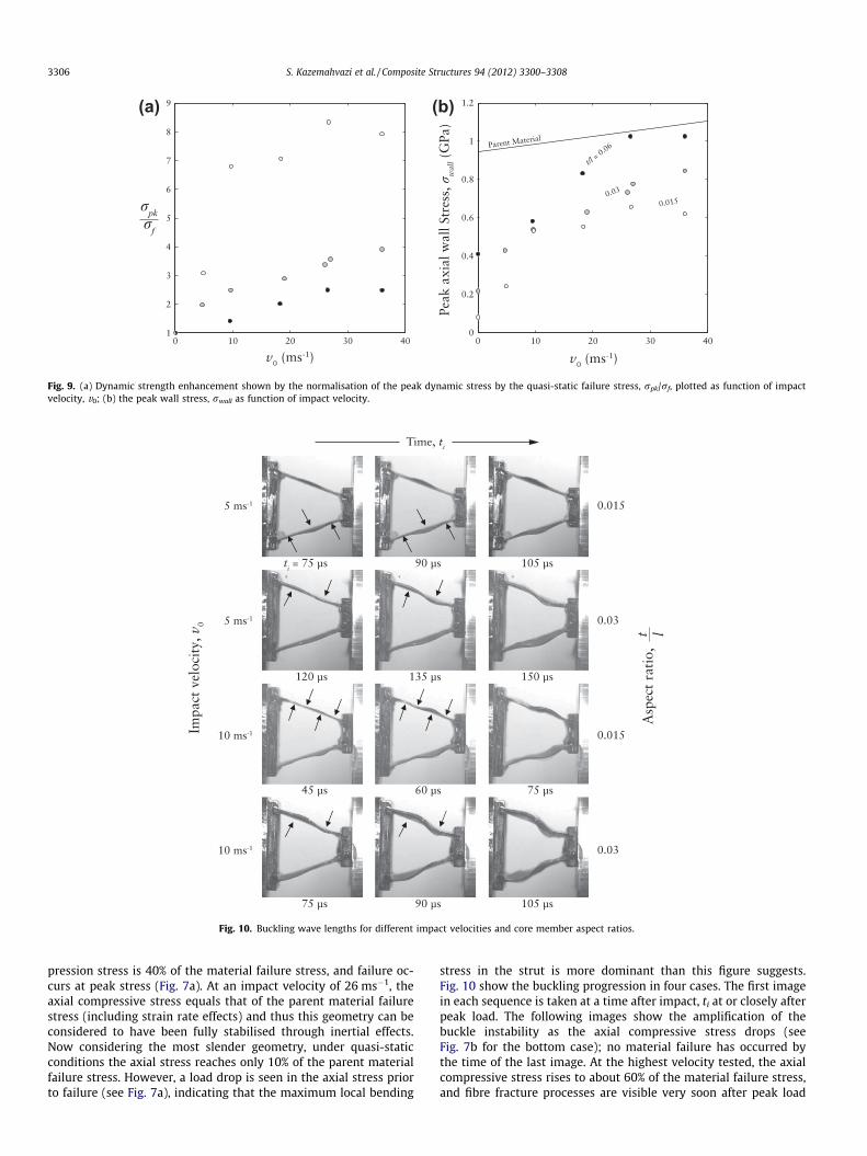
The dynamic strength enhancement of a strut is defined by thepeak stress rpk measured under impact at a velocity v0, normalisedby the quasi-static strength rf of a strut of the same value of t/l.Fig. 9a shows the dynamic strength enhancement (rpk/rf), as func-tion of impact velocity v0, for the three values of t/l. First, strengthenhancement is observed for all geometries with the most slenderstruts (t/l = 0.015) showing the most pronounced enhancement,achieving 7 or 8 times the strength of the quasi-static peak stress.For the most stubby strut where t/l = 0.06, strength enhancement ismuch less, achieving a factor of just over 2. The strength enhance-ment is monotonic although non-linear. For the most slender strut,there is a large increase in the dynamic strength enhancement atthe low velocity range (high sensitivity). At higher velocities the
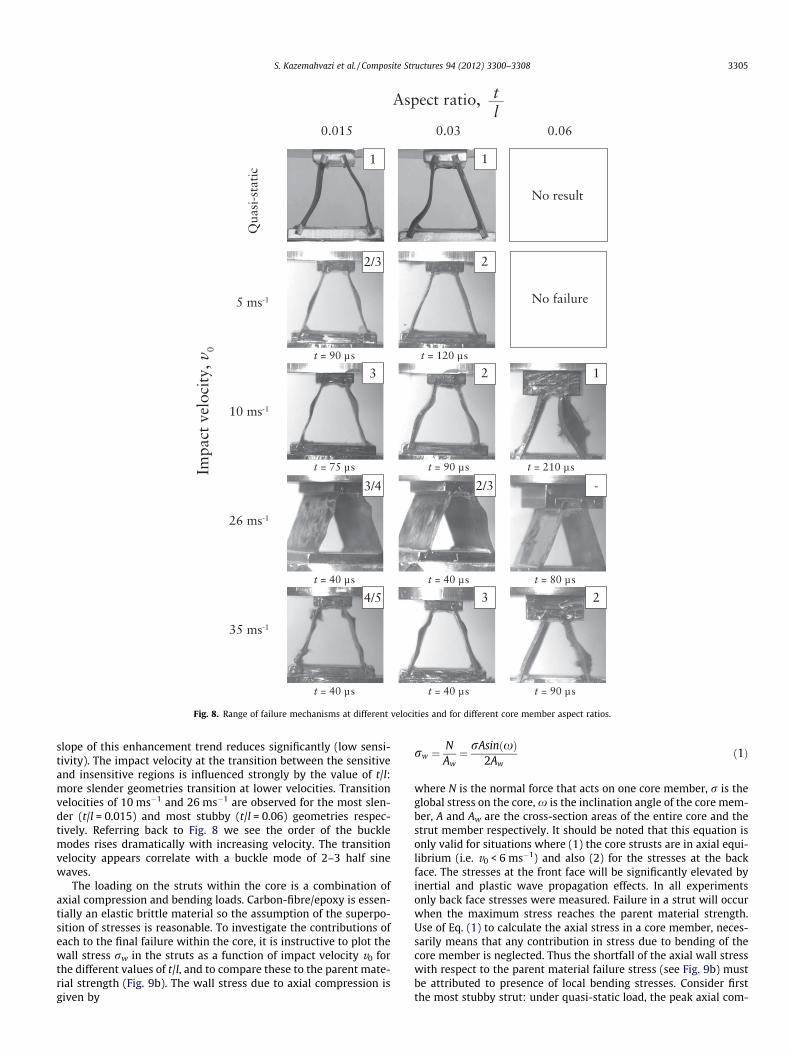
Fig. 8. Range of failure mechanisms at different velocities and for different core member aspect ratios.
S. Kazemahvazi et al. / Composite Structures 94 (2012) 3300–3308 3305
slope of this enhancement trend reduces significantly (low sensi-tivity). The impact velocity at the transition between the sensitiveand insensitive regions is influenced strongly by the value of t/l:more slender geometries transition at lower velocities. Transitionvelocities of 10 ms�1 and 26 ms�1 are observed for the most slen-der (t/l = 0.015) and most stubby (t/l = 0.06) geometries respec-tively. Referring back to Fig. 8 we see the order of the bucklemodes rises dramatically with increasing velocity. The transitionvelocity appears correlate with a buckle mode of 2–3 half sinewaves.
The loading on the struts within the core is a combination ofaxial compression and bending loads. Carbon-fibre/epoxy is essen-tially an elastic brittle material so the assumption of the superpo-sition of stresses is reasonable. To investigate the contributions ofeach to the final failure within the core, it is instructive to plot thewall stress rw in the struts as a function of impact velocity v0 forthe different values of t/l, and to compare these to the parent mate-rial strength (Fig. 9b). The wall stress due to axial compression isgiven by
rw ¼NAw¼ rAsinðxÞ
2Awð1Þ
where N is the normal force that acts on one core member, r is theglobal stress on the core, x is the inclination angle of the core mem-ber, A and Aw are the cross-section areas of the entire core and thestrut member respectively. It should be noted that this equation isonly valid for situations where (1) the core strusts are in axial equi-librium (i.e. v0 < 6 ms�1) and also (2) for the stresses at the backface. The stresses at the front face will be significantly elevated byinertial and plastic wave propagation effects. In all experimentsonly back face stresses were measured. Failure in a strut will occurwhen the maximum stress reaches the parent material strength.Use of Eq. (1) to calculate the axial stress in a core member, neces-sarily means that any contribution in stress due to bending of thecore member is neglected. Thus the shortfall of the axial wall stresswith respect to the parent material failure stress (see Fig. 9b) mustbe attributed to presence of local bending stresses. Consider firstthe most stubby strut: under quasi-static load, the peak axial com-
(a) (b)
Fig. 9. (a) Dynamic strength enhancement shown by the normalisation of the peak dynamic stress by the quasi-static failure stress, rpk/rf, plotted as function of impactvelocity, v0; (b) the peak wall stress, rwall as function of impact velocity.
Fig. 10. Buckling wave lengths for different impact velocities and core member aspect ratios.
3306 S. Kazemahvazi et al. / Composite Structures 94 (2012) 3300–3308
pression stress is 40% of the material failure stress, and failure oc-curs at peak stress (Fig. 7a). At an impact velocity of 26 ms�1, theaxial compressive stress equals that of the parent material failurestress (including strain rate effects) and thus this geometry can beconsidered to have been fully stabilised through inertial effects.Now considering the most slender geometry, under quasi-staticconditions the axial stress reaches only 10% of the parent materialfailure stress. However, a load drop is seen in the axial stress priorto failure (see Fig. 7a), indicating that the maximum local bending
stress in the strut is more dominant than this figure suggests.Fig. 10 show the buckling progression in four cases. The first imagein each sequence is taken at a time after impact, ti at or closely afterpeak load. The following images show the amplification of thebuckle instability as the axial compressive stress drops (seeFig. 7b for the bottom case); no material failure has occurred bythe time of the last image. At the highest velocity tested, the axialcompressive stress rises to about 60% of the material failure stress,and fibre fracture processes are visible very soon after peak load
S. Kazemahvazi et al. / Composite Structures 94 (2012) 3300–3308 3307
(bottom left image in Fig. 8). Even at these velocities it is apparentthat the bending stress still contributes significantly to the failure ofthese struts. In contrast, strengthening due to material rate effectsare small, accounting for a maximum of 15% at the highest velocityv0 = 35 ms�1, recall Fig. 6b.
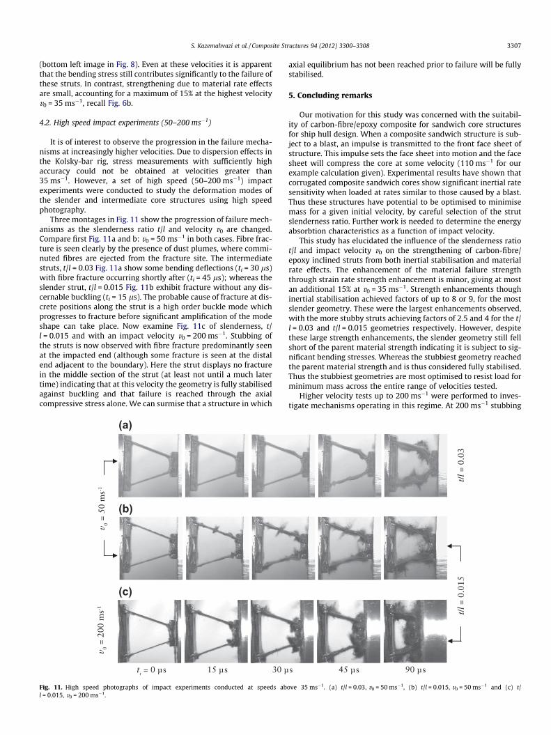
4.2. High speed impact experiments (50–200 ms�1)
It is of interest to observe the progression in the failure mecha-nisms at increasingly higher velocities. Due to dispersion effects inthe Kolsky-bar rig, stress measurements with sufficiently highaccuracy could not be obtained at velocities greater than35 ms�1. However, a set of high speed (50–200 ms�1) impactexperiments were conducted to study the deformation modes ofthe slender and intermediate core structures using high speedphotography.
Three montages in Fig. 11 show the progression of failure mech-anisms as the slenderness ratio t/l and velocity v0 are changed.Compare first Fig. 11a and b: v0 = 50 ms�1 in both cases. Fibre frac-ture is seen clearly by the presence of dust plumes, where commi-nuted fibres are ejected from the fracture site. The intermediatestruts, t/l = 0.03 Fig. 11a show some bending deflections (ti = 30 ls)with fibre fracture occurring shortly after (ti = 45 ls); whereas theslender strut, t/l = 0.015 Fig. 11b exhibit fracture without any dis-cernable buckling (ti = 15 ls). The probable cause of fracture at dis-crete positions along the strut is a high order buckle mode whichprogresses to fracture before significant amplification of the modeshape can take place. Now examine Fig. 11c of slenderness, t/l = 0.015 and with an impact velocity v0 = 200 ms�1. Stubbing ofthe struts is now observed with fibre fracture predominantly seenat the impacted end (although some fracture is seen at the distalend adjacent to the boundary). Here the strut displays no fracturein the middle section of the strut (at least not until a much latertime) indicating that at this velocity the geometry is fully stabilisedagainst buckling and that failure is reached through the axialcompressive stress alone. We can surmise that a structure in which
(a)
(b)
(c)
Fig. 11. High speed photographs of impact experiments conducted at speeds abl = 0.015, v0 = 200 ms�1.
axial equilibrium has not been reached prior to failure will be fullystabilised.
5. Concluding remarks
Our motivation for this study was concerned with the suitabil-ity of carbon-fibre/epoxy composite for sandwich core structuresfor ship hull design. When a composite sandwich structure is sub-ject to a blast, an impulse is transmitted to the front face sheet ofstructure. This impulse sets the face sheet into motion and the facesheet will compress the core at some velocity (110 ms�1 for ourexample calculation given). Experimental results have shown thatcorrugated composite sandwich cores show significant inertial ratesensitivity when loaded at rates similar to those caused by a blast.Thus these structures have potential to be optimised to minimisemass for a given initial velocity, by careful selection of the strutslenderness ratio. Further work is needed to determine the energyabsorbtion characteristics as a function of impact velocity.
This study has elucidated the influence of the slenderness ratiot/l and impact velocity v0 on the strengthening of carbon-fibre/epoxy inclined struts from both inertial stabilisation and materialrate effects. The enhancement of the material failure strengththrough strain rate strength enhancement is minor, giving at mostan additional 15% at v0 = 35 ms�1. Strength enhancements thoughinertial stabilisation achieved factors of up to 8 or 9, for the mostslender geometry. These were the largest enhancements observed,with the more stubby struts achieving factors of 2.5 and 4 for the t/l = 0.03 and t/l = 0.015 geometries respectively. However, despitethese large strength enhancements, the slender geometry still fellshort of the parent material strength indicating it is subject to sig-nificant bending stresses. Whereas the stubbiest geometry reachedthe parent material strength and is thus considered fully stabilised.Thus the stubbiest geometries are most optimised to resist load forminimum mass across the entire range of velocities tested.
Higher velocity tests up to 200 ms�1 were performed to inves-tigate mechanisms operating in this regime. At 200 ms�1 stubbing
ove 35 ms�1. (a) t/l = 0.03, v0 = 50 ms�1, (b) t/l = 0.015, v0 = 50 ms�1 and (c) t/

3308 S. Kazemahvazi et al. / Composite Structures 94 (2012) 3300–3308
of the most slender strut was observed with no discernable buck-ling. Thus it is expected that the peak axial wall strength measuredat the back face would be very close to the strength of the parentmaterial.
Acknowledgements
The financial support for this investigation has been providedby The Office of Naval Research (ONR) through programme officerDr. Yapa D.S. Rajapakse (Grant No. N00014–07-1–0344).
Appendix A. Taylor analysis
Consider a sandwich panel with face sheets of thickness tf sep-arated by some thick core c. Suppose that this panel is subjected toa pressure wave, p, with nearly instantaneous pressure rise to apeak pressure p0, which then decays exponentially with a timeconstant h, as described by the equation
pðtÞ ¼ p0e�t=h: ðA:1Þ
The magnitude of the pressure wave and its decay time, depends onthe mass and type of explosive material, distance to the structure aswell as the media through which the shock wave is propagated. Acharge of 1 kg TNT produces a peak pressure of approximately100 MPa in water and 10 MPa in air at a distance of 1 m [20,1]. Thedecay times for both pressure waves are in the order of 0.1 ms. Themaximum achievable impulse (for a fully reflected pressure wave),I is given as
I ¼Z 1
02p0e�t=hdt ¼ 2p0h ðA:2Þ
which only occurs in the case when the structure is stationary andrigid, i.e. no deformation occurs. The actual impulse which is trans-mitted to the face, Itrans, is given by,
Itrans ¼ fI; ðA:3Þ
where,
f � w�w=w�1; ðA:4Þ
and w is the fluid–structure interaction parameter, w = qwcwh/mf,where qw,cw and mf are density of the media, speed of sound inthe media and mass per unit area of the face sheet respectively.The initial velocity of the front face is given by,
v0 ¼Itrans
qf tf; ðA:5Þ
where qf and tf are the density and thickness of the face sheetrespectively.
References
[1] Fleck N, Deshpande V. J Appl Mech 2004;71:1–16.[2] Xue Z, Hutchinson J. Int J Impact Eng 2004;30:1283–305.[3] Deshpande VS, Ashby MF, Fleck NA. J Mech Phys Solids 2001;49:1747–69.[4] Rubino V, Deshpande V, Fleck N. Eur J Mech 2009;28:14–24.[5] Côté F, Deshpande V, Fleck NA, Evans AG. Int J Solids Struct 2006;43:6220–42.[6] Radford D, McShane G, Deshpande V, Fleck N. J Appl Mech 2007;74:658–67.[7] Calladine CR, English RW. Int J Mech Sci 1984;26:689–701.[8] Tilbrook MT, Radford DD, Deshpande VS, Fleck NA. Int J Solids Struct
2007;44:6101–23.[9] Ferri E, Antinucci E, He MY, Hutchinson JW, Zok FW, Evans AG. J Mech Mater
Struct 2006;1:1345–65.[10] Vaughn JHD. J Mech Mater Struct 2006;25:1–12.[11] Kazemahvazi S, Zenkert D. Compos Sci Technol 2009;69:913–9.[12] Kazemahvazi S, Tanner D, Zenkert D. Compos Sci Technol 2009;69:920–5.[13] Russell BP, Deshpande VS, Wadley HNG. J Mech Mater Struct 2008;3:1315–40.[14] Russell BP, Liu T, Fleck NA, Deshpande VS. J Appl Mech 2011;78:031008–15.[15] Russell BP, Liu T, Fleck NA, Deshpande VS. Int J Impact Eng 2011.[16] Russell BP, Malcom A, Wadley H, Deshpande VS. J Mech Mater Struct
2010;5:477–93.[17] Taylor GI. The pressure and impulse of submarine explosion waves on plates.
The scientific papers of G.I. Taylor, Vol. III. Cambridge, UK: Cambridge Univ.Press; 1963.
[18] Kolsky H. P Phys Soc. Section B 1949;62:676–700.[19] Radford D, Deshpande V, Fleck N. Int J Impact Eng 2005;9:1152–71.[20] Ashby NFMF, Evans AG, Gibson L, Hutchinson J, Wadley H. Metal foams: a
design guide. London: Butterworth Heinemann; 2000.