impact of apparent reactance injected by tcsr on distance
TRANSCRIPT

POWER ENGINEERING AND ELECTRICAL ENGINEERING VOLUME: 11 | NUMBER: 3 | 2013 | JUNE
Impact of Apparent Reactance Injected by TCSR on
Distance Relay in Presence Phase to Earth Fault
Mohamed ZELLAGUI 1, Abdelaziz CHAGHI 1
1LSP-IE Research Laboratory, Department of Electrical Engineering, Faculty of Technology, University ofBatna, Campus CUB, Street Med El Hadi Boukhlouf, 050 00, Batna, Algeria
[email protected], az [email protected]
Abstract. This research paper presents the impactstudy of apparent reactance injected by series Flexi-ble AC Transmission System (FACTS) i.e. Thyris-tor Controlled Series Reactor (TCSR) on the measuredimpedance of a 400 kV single electrical transmissionline in the presence of phase to earth fault with faultresistance. The study deals with an electrical transmis-sion line of Eastern Algerian transmission networksat Group Sonelgaz (Algerian Company of Electrical)compensated by TCSR connected at the midpoint ofthe transmission line. This compensator used to in-ject voltage and reactive power is controlled by TCSR.The simulations results investigate the three impactsof the apparent reactance injected by TCSR (XTCSR)on transmission line protected by distance relay pro-tection. The impacts concern the active and reactivepower, the line impedance (reactance and resistance),and the short circuit parameters (symmetrical currents,line currents, symmetrical voltages and line voltagesas well as the measured impedance by relay (resistanceand reactance) in the presence of earth fault These im-pacts are investigated in order to improve the perfor-mances of distance relay protection. More the impact ofXTCSR by three TCSR for cases studies is presented.
Keywords
Apparent reactance, distance protection, earthfault, measured impedance, symmetrical com-ponents, TCSR, transmission line.
1. Introduction
Electrical power systems have to be planned, projected,constructed, commissioned and operated in such a wayto enable a safe, reliable and economical supply of theload. The knowledge of the equipment loading at thetime of commissioning, the prediction is necessary in
the future for the design and determination of the rat-ing of the individual equipment and of the power sys-tem as a whole. Faults, i.e., short-circuits in the powersystem cannot be avoided despite careful planning anddesign, good maintenance and thorough operation ofthe system. This implies influences from outside thesystem, such as faults following lightning strokes intophase-conductors of overhead lines and damages of ca-bles due to earth construction works as well as inter-nal faults due to ageing of insulation materials [1].Fault currents therefore have an important influenceon the design and operation of power systems equip-ment. More than 83 % of the occurred faults on the220 and 400 kV overhead transmission networks in Al-gerian Company of Electrical and Gas [2] are singlephase to ground type.
Distance protection relays have been widely appliedas the primary protection in high voltage transmissionlines due to their simple operating principle and capa-bility to work independently under most circumstances[3]. The basic operation principle of distance relay isbased on the fact that the line impedance is fairly con-stant with respect to the line length. However, theimplementation of FACTS controllers in power systemtransmission for enhancing the power system controlla-bility and stability have introduced new power systemissues in the field of power system protection that mustbe considered and analyzed [4].
There are two generations for realization of powerelectronics based FACTS controllers: the first genera-tion employs conventional thyristors switched capaci-tors and reactors, and quadrature tap-changing trans-formers while the second generation employs gate turn-off (GTO) thyristors switched converters as a volt-age source converters (VSCs). The first generationhas resulted in the Static Var Compensator (SVC),the Thyristor Controlled Series Capacitor (TCSC),the Thyristor Controlled Phase Shifter (TCPS), andthe Thyristor Controlled Series Reactor (TCSR) [5].The second generation has produced the Static Syn-chronous Compensator (STATCOM), the Static Syn-
c© 2013 ADVANCES IN ELECTRICAL AND ELECTRONIC ENGINEERING 156

POWER ENGINEERING AND ELECTRICAL ENGINEERING VOLUME: 11 | NUMBER: 3 | 2013 | JUNE
chronous Series Compensator (SSSC), the GTO Con-trolled Series Capacitor (GCSC), the Unified PowerFlow Controller (UPFC), and the Interline Power FlowController (IPFC) [6]. The two groups of FACTS con-trollers have distinctly different operating and perfor-mance characteristics. In the presence of series FACTSdevices, the conventional distance relay characteristicssuch as MHO and quadrilateral are greatly subjectedto mal-operation in the form of overreaching or under-reaching the fault point [7]. Therefore, the conven-tional relay characteristics may not work properly inthe presence of FACTS device.
The presence of the FACTS devices in the faultedloop introduces changes to the line parameters seen bythe distance relay. The impact of FACTS device wouldaffect both the steady state and transient trajectory ofthe apparent impedance seen by distance relays due tothe fast response time of FACTS controllers with re-spect to that of the protective devices. The impact ofFACTS devices on distance protection varies depend-ing on the type of FACTS device used, the applicationfor which it is applied and the location of the FACTSdevice in the power system, the performance evaluationof distance protection scheme in the presence of FACTScontrollers, which affect the apparent impedance calcu-lations at relay point, has been carried out in [7]. Theapparent impedance calculations are generally carriedout using power frequency components of voltage andcurrent measured at relay point.
The impact of the first generation on distance pro-tection has been reported for general research on theinfluence of SVC on the transmission lines protec-tion in [8] while the impact for apparent substanceinjected on measured impedance (Zseen) in presenceinter phase faults for different locality, and in refer-ence [9] acomparing effects of two types for SVC (TCRand TSC) on MHO distance protection setting zone in400 kV Algerian transmission line. The general im-pact of TCSC on the transmission line protection isthe study in [10] while the impact on communication-aided distance protection schemes and its mitigationis reported in [11]. In [12] the Zseen by distance relayfor inter phase faults with TCSC on a double trans-mission line high voltage is being studied and in [13]the variation of Zseen by distance relay for inter phasefaults in the presence of TCSC on adjacent transmis-sion line by considering MOV Operation is investi-gated. The effects of voltage transformers connectionpoint on Zseen at relaying point for inter phase faults isalso reported in [14]. Comparing TCSC placements ondouble circuit line at mid-point and at ends from mea-sured impedance point of view is mentioned in [15],and impact of TCSC on Zseen by MHO distance relayon 400 kV Algerian transmission line in the presence ofphase to earth fault with fault resistance is reported in[16]. For the impact of TCSC on distance protection in
[17] is studying the new settings zones for distance re-lay based Artificial Neural Network (ANN) techniqueon a single transmission line.
The impact of second generation, specially theSTATCOM is studying the performance evaluation ofdistance protection scheme which affect the apparentimpedance calculations at relay point, has been carriedout in [18], and the impact for apparent substance in-jected on Zseen in presence inter phase faults is also re-ported [19]. The general impact of SSSC on the trans-mission line protection is the study in [20] while theimpact on fault condition on Zseen in [21] is study-ing the locus of apparent impedance of distance pro-tection while the impact on reactive power conditionand in paper [22] is study the Zseen in presence interphase faults. For the impact of GCSC on the Zseen
by MHO distance protection for phase to earth faultin the presence with fault resistance is study in [23],[24]. The performance evaluation of fault componentdistance relay for protection of lines compensated byUPFC in [25], [26], and compensated by IPFC in [27].
In this research paper, study the impact of apparentreactance injected by three TCSR on Algerian trans-mission line protected by distance relay protection inpresence single phase (phase A) to earth fault withfault resistance have been investigated in order to im-prove the performances of relay. The three impactsstudy is:
• Impacts on active and reactive power of transmis-sion line protected at load busbar, and the param-eters on protected transmission line.
• Impact on the parameters of short circuit calcu-lation: symmetrical components of currents andvoltage, line currents and voltages.
• Impacts on parameters of measured impedance bydistance relay (resistance and reactance).
2. Apparent Reactance In-jected by TCSR on Trans-mission Line
The compensator TCSR mounted on Fig. 1 consists ofvariable inductance (L1) connected in a series with thetransmission line controlled by thyristors mounted inanti-parallel and controlled by a firing angle (α) whichvaries between 90 and 180 , and a fixed value induc-tance (L2) connected in shunt [6], [28].
This compensator can be modeled as a variable re-actance (XTCSR) as shows in Fig. 2.
From Fig. 2, the apparent reactance of the TCSRinjected on transmission line is defined by the following
c© 2013 ADVANCES IN ELECTRICAL AND ELECTRONIC ENGINEERING 157

POWER ENGINEERING AND ELECTRICAL ENGINEERING VOLUME: 11 | NUMBER: 3 | 2013 | JUNE
Fig. 1: Principal operation of TCSR.
Fig. 2: Apparent reactance injected by TCSR.
equation [6], [17], [28]:
XTCSR(α) = XL1(α)//XL2 =XL1(α)XL2
XL(α) +XL2. (1)
The reactance of the first inductance XL1 (α) con-trolled by thyristors is defined by equation:
XL1(α) = XL1−max
[π
π − 2α− sin(2α)
], (2)
whereXL1−max = L1 · ω. (3)
And the second reactance of inductance (XL2) is de-fined by the formula:
XL2 = L2 · ω. (4)
From Eq. (2) and (4), the final equation Eq. (1) be-comes:
XTCSR(α) =
L2L1ω2
(π
π − 2α− sin(2α)
)ω
(L2 + L1
(π
π − 2α− sin(2α)
)) . (5)
The active (P ) and reactive (Q) powers on transmis-sion line with TCSR are defined by following equations:
P (δ) =VA · VB
ZAB +XTCSR(α)sin(δ), (6)
Q(δ) =V 2B
ZAB +XTCSR− VA · VBZAB +XTCSR
cos(δ), (7)
where, ZAB is impedance of transmission line, δ is lineangle, VA and VB voltages on the extremity of trans-mission line.
3. Phase to Earth Fault Calcu-lation in the Presence of aTCSR
Figure 3 shows transmission line in case of a singlephase (phase A) to ground fault at busbar B with faultresistance (RF ) in the presence of a series compensatorTCSR inserted on the midline, while Fig. 4 shows theequivalent circuit.
Fig. 3: Transmission line with TCSR.
Fig. 4: Earth fault equivalent circuit with TCSR.
With TCSR inserted in the midline, the newimpedance of transmission line (ZAB−TCSR) is:
ZAB−TCSR = RAB + j [XAB +XTCSR(α)] . (8)
The basic equations for this type of earth fault [16],[29], [30] are:
Ib = Ic = 0. (9)
Va = V1 + V2 + V0 = RF · Ia 6= 0. (10)
The symmetrical components of currents are: I0I1I2
=1
3
1 1 11 a a2
1 a2 a
IAIBIC
. (11)
c© 2013 ADVANCES IN ELECTRICAL AND ELECTRONIC ENGINEERING 158
POWER ENGINEERING AND ELECTRICAL ENGINEERING VOLUME: 11 | NUMBER: 3 | 2013 | JUNE
From Eq. (9) and matrix (11), the symmetrical com-ponents of currents become:
I1 + I2 + I0 =IA3. (12)
The symmetrical components of voltages are: V0V1V2
=1
3
1 1 11 a a2
1 a2 a
VAVBVC
. (13)
From Eq. (10) and matrix (13), the direct componentsof voltage become:
V1 = − (V0 + V2) +RF · IA, (14)
and
Vs + VTCSR − I1[ZAB.1
2+XTCSR.1 +
ZAB.1
2
]=
= A+B + C,
(15)
where, the coefficients A, B and C are defined as:
A = −1
3
[−(ZAB.0
2+XTCSR.0 +
ZAB.0
2
)· I0], (16)
B = −1
3
[−(ZAB.2
2+XTCSR.2 +
ZAB.2
2
)· I2], (17)
C = RF · IA. (18)
The coefficients ZAB−T and ZTCSR−T are definedfor simplicity as:
ZAB−T = ZAB.1 + ZAB.2 + ZAB.0. (19)
XTCSR−T = XTCSR.1 +XTCSR.2 +XTCSR.0. (20)
Vs + VTCSR =
IA3
[ZAB−T
2+XTCSR−T +
ZAB−T
2
]+RF · IA.
(21)
From Eq. (19), (20) and (21), the current at phase (A)currents in presence TCSR on midline is given by:
IA =3 · (VS + VTCSR)(
ZAB−T
2
)+XTCSR−T +
(ZAB−T
2
)+ 3 ·RF
. (22)
From Eq. (12), the symmetrical components of cur-rents in presence TCSR on midline are:
I1 = I2 = I0 =VS + VTCSR(
ZAB−T
2
)+XTCSR−T +
(ZAB−T
2
)+ 3 ·RF
. (23)
The direct components of voltages in presence TCSRare:
V1 = VS + VTCSR
−(ZAB.1
2+XTCSR.1 +
ZAB.1
2
)· I1
⇒ V1 =(VS + VTCSR) ·
[Z′AB +X
′TCSR + 3 ·RF
]ZAB−T
2+XTCSR−T +
ZAB−T
2+ 3 ·RF
,
(24)
where, the coefficients Z′
AB and X′
TCSR are defined as:
Z′
AB = ZAB.2 + ZAB.0 + 2 · ZAB.1. (25)
X′
TCSR = XTCSR.2 +XTCSR.0 − 2 ·XTCSR.1. (26)
The inverse components of voltages in the presenceTCSR are:
V2 = −(ZAB.2
2+XTCSR.2 +
ZAB.2
2
)· I2
⇒ V2 =
− (VS + VTCSR) · [ZAB.2 +XTCSR.2](ZAB−T
2
)+XTCSR−T +
(ZAB−T
2
)+ 3 ·RF
.(27)
The zero components of voltages in presence TCSR are:
V0 = −(ZAB.0
2+XTCSR.0 +
ZAB.0
2
)· I0 −RF · I0
⇒ V0 =
= −(VS + VTCSR) · [ZAB.0 +XTCSR.0 +RF ](ZAB−T
2
)+XTCSR−T +
(ZAB−T
2
)+ 3 ·RF
.(28)
The coefficients Z′
AB and X′
TCSR are defined as:
Z′
2 = ZAB.2 +XTCSR.2. (29)
Z′
0 = ZAB.0 +XTCSR.0. (30)
Sa = 3 · a2 − 1. (31)
Sb = 3 · a− 1. (32)
From Eq. (24), (27) and (28), the three phase volt-ages on transmission line in presence of TCSR are:
VA =3 ·RF · (VS + VTCSR)(
ZAB−T
2
)+XTCSR−T +
(ZAB−T
2
)+ 3 ·RF
. (33)
VB =
(VS + VTCSR) ·[(a2 − a)Z
′2 + (a2 − 1)Z
′0 + SbRF
](ZAB−T
2
)+XTCSR−T +
(ZAB−T
2
)+ 3 ·RF
. (34)
VC =
(VS + VTCSR) ·[(a− a2)Z
′2 + (a− 1)Z
′0 + SbRF
](ZAB−T
2
)+XTCSR−T +
(ZAB−T
2
)+ 3 ·RF
. (35)
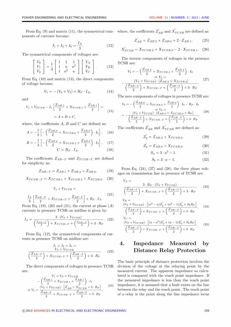
4. Impedance Measured byDistance Relay Protection
The basic principle of distance protection involves thedivision of the voltage at the relaying point by themeasured current. The apparent impedance so calcu-lated is compared with the reach point impedance. Ifthe measured impedance is less than the reach pointimpedance, it is assumed that a fault exists on the linebetween the relay and the reach point. The reach pointof a relay is the point along the line impedance locus
c© 2013 ADVANCES IN ELECTRICAL AND ELECTRONIC ENGINEERING 159
POWER ENGINEERING AND ELECTRICAL ENGINEERING VOLUME: 11 | NUMBER: 3 | 2013 | JUNE
that is intersected by the boundary characteristic ofthe relay. Distance relay has been widely used in theprotection of transmission lines. The basic principle ofoperation of distance protection is shown in Fig. 5 [3].
The input to the distance relay point is the phasevoltages and line currents transformed with the helpof voltage transformer (VT) and current transformers(CT).
Fig. 5: Principal and setting zones for distance protection.
The total impedance of electrical transmission lineAB measured by distance relay without fault is [16],[17], [24], and [31]:
Zseen = KZ · ZAB = (KV T /KCT ) · ZAB , (36)
whereKV T = Vprim/Vsec, (37)
andKCT = Iprim/Isec. (38)
The impedance ZAB is real total impedance of pro-tected transmission line AB, and KV T and KCT are aratio of voltage to current transformers respectively.
The presence of TCSR, the XTCSR has a direct in-fluence on the total impedance of the protected line(ZAB) by distance relay. This effect especially on thereactance XAB and no influence on the resistance RAB ,it is represented in Fig. 6.
The voltage would fall towards zero at the pointof the fault. In case of earth fault in phase (A), theimpedance measured is calculated by flowing equation[3], [15], [16], [17], [18]:
Zseen =VRelay
IRelay=VA/IA +Ko · Io
KZ=
= Rseen + j ·Xseen,(39)
where
Ko =Zo − Z1
3 · Z1, (40)
and
KZ =KCT
KV T. (41)
The coefficient KZ is a ratio of impedance transfor-mers and Ko is coefficient for earth fault.
Fig. 6: Impact of the TCSR on total impedance.
5. Case Study, Results and In-terpretations
The power system studied in this paper is the 400 kVAlgerian electrical transmission networks at AlgerianCompany of Electrical and Gas (group Sonelgaz) whichis shows in Fig. 7 [32].
The distance relay protection is located in the busbarat Ramdane Djamel substation to protect transmissionline between busbar A and busbar B respectively atRamdane Djamel and Oued El Athmania substation inMila. The busbar C is located at Salah Bay substationin Setif.
The series compensator TCSR is installed in midline.The parameters of transmission line are summarized inthe appendix.
Fig. 7: Electrical networks study in presence TCSR [32].
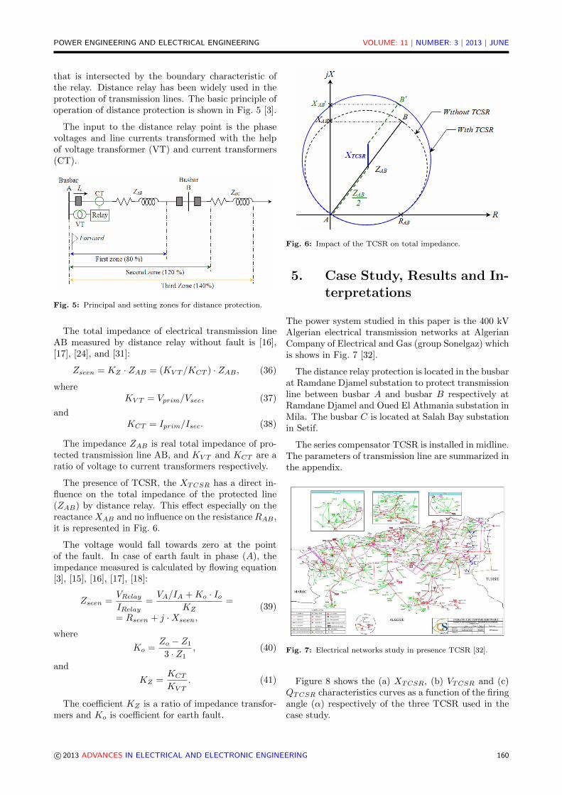
Figure 8 shows the (a) XTCSR, (b) VTCSR and (c)QTCSR characteristics curves as a function of the firingangle (α) respectively of the three TCSR used in thecase study.
c© 2013 ADVANCES IN ELECTRICAL AND ELECTRONIC ENGINEERING 160
POWER ENGINEERING AND ELECTRICAL ENGINEERING VOLUME: 11 | NUMBER: 3 | 2013 | JUNE
(a) XTCSR (α)
(b) VTCSR (α)
(c) QTCSR (α)
Fig. 8: Characteristic curve of TCSR study.
5.1. Impact on Protected Transmis-sion Line
The Fig. 9(a) and 9(b) show the impact of TCSR in-sertion on the active and reactive power variation of
transmission line protected respectively at busbar B(load) with line angle (δ) varied between 0 to 180 .
(a) P (δ)
(b) QL(δ)
Fig. 9: Impact of TCSR on active and reactive power line.
In the presence of TCSR, the active and reactivepower will be reduced following insertion of an induc-tive reactance in the middle point of the transmissionline as show in Fig. 9.
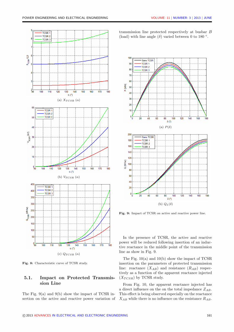
The Fig. 10(a) and 10(b) show the impact of TCSRinsertion on the parameters of protected transmissionline: reactance (XAB) and resistance (RAB) respec-tively as a function of the apparent reactance injected(XTCSR) by TCSR study.
From Fig. 10, the apparent reactance injected hasa direct influence on the on the total impedance ZAB .This effect is being observed especially on the reactanceXAB while there is no influence on the resistance RAB .
c© 2013 ADVANCES IN ELECTRICAL AND ELECTRONIC ENGINEERING 161
POWER ENGINEERING AND ELECTRICAL ENGINEERING VOLUME: 11 | NUMBER: 3 | 2013 | JUNE
(a) RAB(XTCSR)
(b) XAB(XTCSR)
Fig. 10: Impact of TCSR on reactance a resistance transmissionline.
5.2. Impact on Short-Circuit Calcu-lation
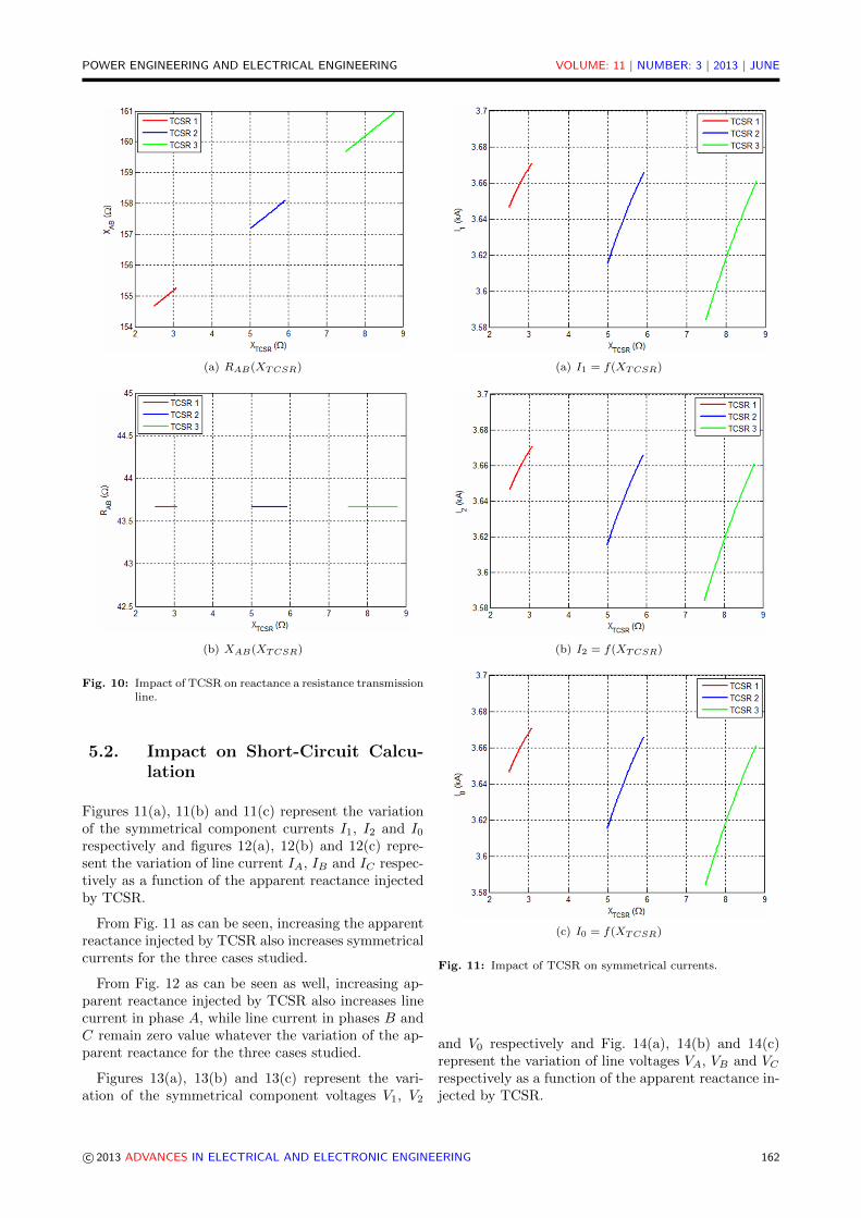
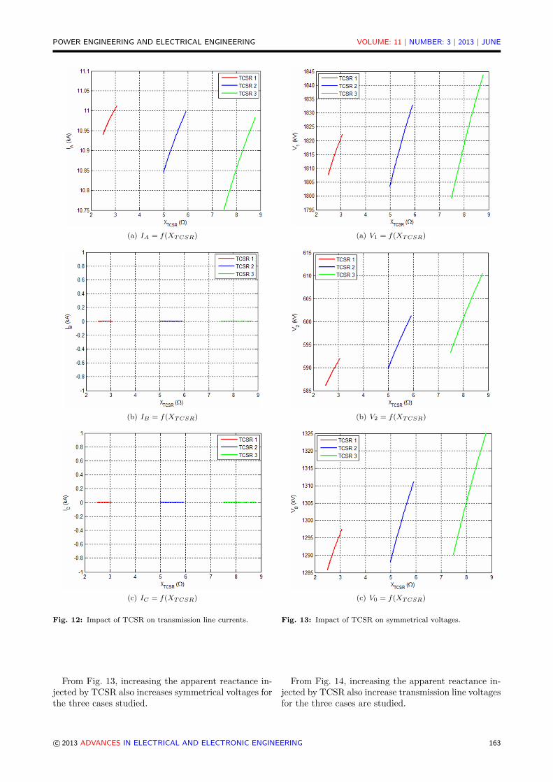
Figures 11(a), 11(b) and 11(c) represent the variationof the symmetrical component currents I1, I2 and I0respectively and figures 12(a), 12(b) and 12(c) repre-sent the variation of line current IA, IB and IC respec-tively as a function of the apparent reactance injectedby TCSR.
From Fig. 11 as can be seen, increasing the apparentreactance injected by TCSR also increases symmetricalcurrents for the three cases studied.
From Fig. 12 as can be seen as well, increasing ap-parent reactance injected by TCSR also increases linecurrent in phase A, while line current in phases B andC remain zero value whatever the variation of the ap-parent reactance for the three cases studied.
Figures 13(a), 13(b) and 13(c) represent the vari-ation of the symmetrical component voltages V1, V2
(a) I1 = f(XTCSR)
(b) I2 = f(XTCSR)
(c) I0 = f(XTCSR)
Fig. 11: Impact of TCSR on symmetrical currents.
and V0 respectively and Fig. 14(a), 14(b) and 14(c)represent the variation of line voltages VA, VB and VCrespectively as a function of the apparent reactance in-jected by TCSR.
c© 2013 ADVANCES IN ELECTRICAL AND ELECTRONIC ENGINEERING 162
POWER ENGINEERING AND ELECTRICAL ENGINEERING VOLUME: 11 | NUMBER: 3 | 2013 | JUNE
(a) IA = f(XTCSR)
(b) IB = f(XTCSR)
(c) IC = f(XTCSR)
Fig. 12: Impact of TCSR on transmission line currents.
From Fig. 13, increasing the apparent reactance in-jected by TCSR also increases symmetrical voltages forthe three cases studied.
(a) V1 = f(XTCSR)
(b) V2 = f(XTCSR)
(c) V0 = f(XTCSR)
Fig. 13: Impact of TCSR on symmetrical voltages.
From Fig. 14, increasing the apparent reactance in-jected by TCSR also increase transmission line voltagesfor the three cases are studied.
c© 2013 ADVANCES IN ELECTRICAL AND ELECTRONIC ENGINEERING 163

POWER ENGINEERING AND ELECTRICAL ENGINEERING VOLUME: 11 | NUMBER: 3 | 2013 | JUNE
(a) VA = f(XTCSR)
(b) VB = f(XTCSR)
(c) VC = f(XTCSR)
Fig. 14: Impact of TCSR on transmission line voltages.
5.3. Impact on the MeasuredImpedance
Figures 15(a) and 15(b) show the variation of resistanceRseen and reactance Xseen measured by distance relay
respectively as a function of reactance XTCSR for dif-ferent cases studied.
(a) Rseen = f(XTCSR)
(b) Xseen = f(XTCSR)
Fig. 15: Impact of the TCSR on the measured impedance.
From Fig. 15, increasing the apparent reactance de-crease the resistance measured and increases the reac-tance measured by relay for the three cases study.
In presence TCSR for three cases studied the valuesof short-circuit calculation is varied between minimumand maximum value as reported in flowing Tab. 1.
Table 1 represents the minimum and maximum val-ues for short circuit parameters. These values are im-portant for calculating the settings for Overcurrent re-lay protection in the presence in case of ground fault,The new setting for transmission line composed byTCSR is between minimum and maximum value offault current, where the courant IF = IA.
Table 2 represents the minimum and maximum val-ues for impedance measured by distance relay protec-tion. These values are important for calculating thesettings zones parameters for distance relay protected
c© 2013 ADVANCES IN ELECTRICAL AND ELECTRONIC ENGINEERING 164

POWER ENGINEERING AND ELECTRICAL ENGINEERING VOLUME: 11 | NUMBER: 3 | 2013 | JUNE
Tab. 1: Minimum and maximum value for short circuit parameters.
Case No. 1 Case No. 2 Case No. 3Min Max Min Max Min Max
α () 90 180 90 180 90 180XTCSR (Ω) 2,500 3,070 5,000 5,920 7,500 8,780VTCSR (kV) 0,000 20,00 0,000 40,00 0,000 60,00
QTCSR (MVar) 0,000 130,0 0,000 270,0 0,000 410,0I1 (kA) 3,646 3,670 3,615 3,666 3,584 3,660I2 (kA) 3,646 3,670 3,615 3,666 3,584 3,660I0 (kA) 3,646 3,670 3,615 3,666 3,584 3,660IA (kA) 10,939 11,012 10,845 10,997 10,751 10,982IB (kA) 0,000 0,000 0,000 0,000 0,000 0,000IC (kA) 0,000 0,000 0,000 0,000 0,000 0,000V1 (kV) 1807,6 1822,3 1803,3 1833,0 1700,1 1843,7V2 (kV) 586,07 592,00 589,71 592,00 583,27 610,51V0 (kV) 1285,7 1297,4 1288,0 1311,2 1290,2 1324,9VA (kV) 1047,3 1055,7 1044,7 1061,9 1042,2 1068,0VB (kV) 3155,6 3182,6 3154,0 3207,9 3152,2 3233,1VC (kV) 2176,5 2195,4 2176,6 2214,3 2176,7 2233,4
Tab. 2: Minimum and maximum value of the measured impedance parameters by relay.
Case No. 1 Case No. 2 Case No. 3Min Max Min Max Min Max
α () 90 180 90 180 90 180XTCSR (Ω) 2,500 3,070 5,000 5,920 7,500 8,780VTCSR (kV) 0,000 20,00 0,000 40,00 0,000 60,00
QTCSR (MVar) 0,000 130,0 0,000 270,0 0,000 410,0Rseen (Ω) 0,3083 0,3084 0,3081 0,3082 0,3079 0,3080Xseen (Ω) 0,2414 0,2424 0,2456 0,2471 0,2497 0,2519
transmission line compensated by series FACTS de-vices i.e. TCSR.
Practically the values for measured impedance rep-resented in Tab. 1 and Tab. 2 are calculated by dis-tance relay after the courant and voltage measure inthe presence of fault on transmission line.
6. Conclusion
A procedure of short circuit parameters calculation andmeasured impedance by distance relay of system withTCSR on transmission line 400 kV during single phaseto ground fault with fault resistance is outlined. Inthis research paper, the effect of apparent reactanceinjected by TCSR on the impedance measured by pro-tective relay protection is being considered.
The results are presented in relation to a typical elec-trical transmission system employing different TCSR(130 MVar/20 kV, 270 MVar/40 kV, 410 MVar/60 kV).The compensator is connected at the midpoint of a pro-tected transmission line by distance relay. The simu-lation results show clearly the impact of TCSR on dis-tance relay performance. The impedance Zseen is influ-enced by the injected reactance XTCSC of the TCSR.Since deviation of the measured impedance is not con-stant, because of the varying parameters of the injected
reactance by TCSR, adaptive methods should be uti-lized.
In order to increase the total system protectionperformance and avoid unwanted tripping of circuitbreaker in the presence of series FACTS devices com-pensator on electrical transmission line care must betaken. For specified systems, settings for different pro-tection zones can be achieved based on the proposedsetting principles. Moreover following state of TCSRchanging the setting relay of overcurrent protection isnecessary.
Appendix
Power source:Us = 11 kV,fn = 50 Hz,STR = 200 MVA.
Power transformer :UTR = 11/400 kV,Coupling: Y/∆,STR = 200 MVA,XTR1 = j0, 235 Ω,XTR0 = j0, 751 Ω.
Transmission line:UL = 400 kV, ∆V = 35 kV, Length = 360 km,
c© 2013 ADVANCES IN ELECTRICAL AND ELECTRONIC ENGINEERING 165
POWER ENGINEERING AND ELECTRICAL ENGINEERING VOLUME: 11 | NUMBER: 3 | 2013 | JUNE
Z1 = 0, 1213 + j0, 4227 Ω/km,Z0 = 0, 3639 + j1, 2681 Ω/km.
TCSR study :Case 1. VMax = 20 kV, QMax = 130 MVar, L1 =0, 0424 H, L2 = 0, 0080 H.Case 2. VMax = 40 kV, QMax = 270 MVar, L1 =0, 1019 H, L2 = 0, 0159 H.Case 3. VMax = 60 kV, QMax = 410 MVar, L1 =0, 1637 H, L2 = 0, 0239 H.
Fault conditions:nF = 100 %,RF = 0 to 100 Ω.
References
[1] SCHLABBACH, J. Short-Circuit Currents. 2. ed.London: Institution of Engineering and Technolo-gy, 2008. ISBN 9780863415142.
[2] Group Sonelgaz/OS. Rapport: Statistics of Faultson Electrical Networks 220 kV and 400 kV. Alge-ria, 2012.
[3] ZIGLER, G. Numerical Distance Protection:Principles and Applications. 3. ed. Munich: Pub-licis MCD, 2008. ISBN 978-3895781421.
[4] IEEE Standard 1534. IEEE Recommended Prac-tice for Specifying Thyristor Controlled Series Ca-pacitor. New York: IEEE Power and Energy So-ciety, 2009.
[5] ZHANG, X. P., C. REHTANZ and B. PAL. Flexi-ble AC Transmission Systems: Modeling and Con-trol. Berlin: Springer Verlag, 2006. ISBN 978-3-642-06786-0.
[6] MATHUR, R. M. and R. K. VARMA. Thyristor-Based FACTS Controllers for Electrical Transmis-sion Systems. New York: John Wiley & Sons,2002. ISBN 978-0-471-20643-9.
[7] DASH, P. K., A. K. PRADHAN and G. PANDA.Apparent Impedance Calculations for DistanceProtected Transmission Lines Employing Series-Connected FACTS Devices. Electric Power Com-ponents and Systems. 2001, vol. 29, no. 7, pp. 577–595. ISSN 1532-5016.
[8] JAMALI, S., A. KAZEMI and H. SHATERI.Measured Impedance by Distance Relay for In-ter Phase Faults in the Presence of SVC onDouble-circuit Lines. In: 11th InternationalConference on Developments in Power Sys-tems Protection, 2012. DPSP 2012. Birmingham:IEEE, 2012, pp. 1–6. ISBN 978-1-84919-620-8.DOI: 10.1049/cp.2012.0052.
[9] ZELLAGUI, M. and A. CHAGHI. Comparing Ef-fects of TCR and TSC on MHO Distance Pro-tection Setting in 400 kV Algerian TransmissionLine. Leonardo Electronic Journal of Practicesand Technologies. 2012, vol. 11, iss. 21, pp. 1–14.ISSN 1583-1078.
[10] KHEDERZADEH, M. and T. S. SIDHU. Im-pact of TCSC on the Protection of Transmis-sion Lines. IEEE Transactions on Power Delivery.2006, vol. 21, iss. 1, pp. 80–87. ISSN 0885-8977.DOI: 10.1109/TPWRD.2005.858798.
[11] SIDHU, T. S. and M. KHEDERZADEH. TCSCImpact on Communication Aided Distance Pro-tection Schemes and Mitigation. IEE Proceedings-Generation, Transmission and Distribution. 2005,vol. 152, iss. 5, pp. 714–728. ISSN 1350-2360.DOI: 10.1049/ip-gtd:20045261.
[12] JAMALI, S., A. KAZEMI and H. SHATERI.Measured Impedance by Distance Relay for InterPhase Faults with TCSC on a Double Circuit Line.In: 18th Australasian Universities Power Engi-neering Conference AUPEC 2008. Sydney: IEEE,2008, pp. 1-6. ISBN 978-0-7334-2715-2.
[13] JAMALI, S., A. KAZEMI and H. SHATERI.Measured Impedance by Distance Relay for In-ter Phase Faults with TCSC on a Double Cir-cuit Line. In: IEEE Region 10 Conference TEN-CON 2008. Hyderabad: IEEE, 2008, pp. 1–6. ISBN 978-1-4244-2408-5. DOI: 10.1109/TEN-CON.2008.4766724.
[14] JAMALI, S., A. KAZEMI and H. SHATERI. Ef-fects of Voltage Transformers Connection Pointon Measured Impedance at Relaying Point forInter Phase Faults in Presence of TCSC. In:IEEE 2nd International on Power and Ener-gy Conference, PECon 2008. Johor Baharu:IEEE, 2008, pp. 553–558. ISBN 978-1-4244-2404-7. DOI: 10.1109/PECON.2008.4762537.
[15] KAZEMI, A., S. JAMALI and H. SHATERI.Comparing TCSC Placements on Double Cir-cuit Line Mid-point and Ends from MeasuredImpedance Point of View. In: IEEE InternationalConference on Industrial Technology. ICIT’2008.Chengdu: IEEE, 2008, pp. 1–6. ISBN 978-1-4244-1705-6. DOI: 10.1109/ICIT.2008.4608453.
[16] ZELLAGUI, M. and A. CHAGHI. Impact ofTCSC on Measured Impedance by MHO DistanceRelay on 400 kV Algerian Transmission Line inPresence of Phase to Earth Fault. Journal of Elec-trical Systems. 2012, vol. 8, no. 3, pp. 273–291.ISSN 1112-5209.
c© 2013 ADVANCES IN ELECTRICAL AND ELECTRONIC ENGINEERING 166
POWER ENGINEERING AND ELECTRICAL ENGINEERING VOLUME: 11 | NUMBER: 3 | 2013 | JUNE
[17] ZELLAGUI, M. A. and CHAGHI. Distance Pro-tection Settings Based Artificial Neural Networkin Presence of TCSR on Electrical TransmissionLine. International Journal of Intelligent Systemsand Applications. 2012, vol. 4, no. 12, pp. 75–85.ISSN 2074-9058.
[18] SHAM, M. V. and V. K. PANDURANGA. Simu-lation Studies on the Distance Relay Performancein the Presence of STATCOM. Journal of Elec-trical Engineering. 2011, vol. 11, no. 3, pp. 1–7.ISSN 1335-3632.
[19] SALEMNI, A., M. KHEDERZADEH and A.GHORBANI. Impact of Static Synchronous Com-pensator (STATCOM) on Performance of Dis-tance Relay. In: IEEE PowerTech. Bucharest:IEEE, 2009, pp. 1–8. ISBN 978-1-4244-2234-0.DOI: 10.1109/PTC.2009.5282187.
[20] SHOJAEI, A., S. M. and MADANI. Analysis ofMeasured Impedance by Distance Relay in Pres-ence of SSSC. In: 5th IET International Confe-rence on Power Electronics, Machines and Drives(PEMD 2010). Brighton: IEEE, 2010, pp. 1–6.DOI: 10.1049/cp.2010.0113.
[21] JAMALI, S. and H. SHATERI. Locus of Appar-ent Impedance of Distance Protection in the Pres-ence of SSSC. European Transactions on Elec-trical Power. 2011, vol. 21, iss. 1, pp. 398–412.ISSN 1546-3109. DOI: 0.1002/etep.449.
[22] JAMALI, S., A. KAZEMI and H. SHA-TERI. Measured Impedance by Distance Re-lay for Inter Phase Faults in Presence ofSSSC. In: IEEE/PES Power Systems Confe-rence and Exposition, 2009 (PSCE 09). Seattle:IEEE, 2009, pp. 1–6. ISBN 978-1-4244-3810-5.DOI: 10.1109/PSCE.2009.4840123.
[23] ZELLAGUI, M. and A. CHAGHI. MeasuredImpedance by MHO Distance Protection forPhase to Earth Fault in Presence GCSC. ACTATechnica Corviniensis - Bulletin of Engineering.2012, vol. 5, iss. 3, pp. 81–86. ISSN 2067-3809.
[24] ZELLAGUI, M. and A. CHAGHI. Impact ofGCSC on Measured Impedance by Distance Relayin the Presence of Single Phase to Earth Fault. In:32th International Conference on Power SystemsEngineering. Dubai: WASET, 2012, pp. 142–149.ISSN 2010-376X.
[25] ZHOU, H., WANG, H., R. K. AGGARWAL andP. BEAUMONT. Performance Evaluation of aDistance Relay as Applied to a TransmissionSystem With UPFC. IEEE Transactions onPower Delivery. 2006, vol. 21, iss. 3, pp. 1137–1147. ISSN 0885-8977. DOI: 10.1109/TP-WRD.2005.861329.
[26] KHEDERZADEH, M. Performance Evaluation ofFault Component Distance Relay for Protectionof Lines Compensated by UPFC. In: 10th IET In-ternational Conference on Developments in PowerSystem Protection (DPSP 2010). Manchester:IEEE, 2010, pp. 1–5. DOI: 10.1049/cp.2010.0248.
[27] POUYAN, M., F. RAZAVI and M. RASHIDI-NEJAD. Performance of Distance Relays in Pre-sence of IPFC. In: IEEE Bucharest PowerTech.Bucharest: IEEE, 2009, pp. 1–6. ISBN 978-1-4244-2234-0. DOI: 10.1109/PTC.2009.5282257.
[28] SEN, K. K. and M. L. SEN. Introduction toFACTS Controllers: Theory, Modeling and Ap-plications. New Jersey: John Wiley & Sons, 2009.ISBN 978-0470478752.
[29] HA, H. X. and B. H. ZHANG. Study on Reac-tance Relays for Single Phase to Earth Fault onEHV Transmission Lines. In: International Con-ference on Power System Technology. Singapore:IEEE, 2004, pp. 1–5, vol.1. ISBN 0-7803-8610-8.DOI: 10.1109/ICPST.2004.1459956.
[30] JAMALI, S. and H. SHATERI. Impedance basedFault Location Method for Single Phase to EarthFaults in Transmission Systems. In: 10th IET In-ternational Conference on Developments in PowerSystem Protection (DPSP 2010). Manchester:IEEE, 2010, pp. 1–4. DOI: 10.1049/cp.2010.0351.
[31] GERIN-LAJOIE, L. A MHO Distance Relay De-vice in EMTP Works. Electric Power SystemsResearch. 2009, vol. 79, no. 3, pp. 484–490.ISSN 0378-7796.
[32] Group Sonelgaz/GRTE. Topologies of ElectricalNetworks 400 kV. Algerian Company of Electri-cal Transmission Network. Algeria, 2012.
About Authors
Mohamed ZELLAGUI was born in Constantine,Algeria, 1984. He received the engineer and M.Sc.degree in Electrical Engineering (Power System) fromdepartment of Electrical Engineering at University ofConstantine, Algeria in 2007 and 2010 respectively,Ph.D. Student and member LSP-IE research labo-ratory from department of Electrical Engineering atBatna University, Algeria. Membership at Interna-tional Association of Engineers (IAENG), and theInstitution of Engineering and Technology (IET). Hisareas of interest include electrical networks, powersystem protection, distance relay and FACTS devices.
Abdelaziz CHAGHI was born in Batna, Alge-ria, 1954. He received his B.Sc. degree from the
c© 2013 ADVANCES IN ELECTRICAL AND ELECTRONIC ENGINEERING 167
POWER ENGINEERING AND ELECTRICAL ENGINEERING VOLUME: 11 | NUMBER: 3 | 2013 | JUNE
University of Oran, Algeria 1980, and M.Sc. from theManchester University, England 1984, and receivedhis Ph.D. from Batna University, Algeria 2004. Heis currently a Professor at department of Facultyof Technology, Electrical Engineering and memberLSP-IE research laboratory at University of Batna.His areas of interest include power systems optimiza-tion, transmission line, harmonic, power quality andFACTS devices.
c© 2013 ADVANCES IN ELECTRICAL AND ELECTRONIC ENGINEERING 168