imp icon2004-x - pow-mech.com€¦ · in the communication era, biffi italia has engineered new...
TRANSCRIPT

In the communication era, Biffi Italia has engineered new advanced solutions to easily communicatewith on-field users and control rooms and to download all the process information and diagnostic data
2000
ICON2000 Release 2004: share your valve process information!
ProductBrochure

2
!@#$ flow control
Features
More than half a century ago Biffi started its business in valve actuation.
Its world-wide leadership has been built through continuous innovation and the ability
to face the new challenges that a fast changing environment comes up with.
It was in 1992 that Biffi started its intelligent actuator campaign.
Since then Biffi Intelligent actuators have been welcomed by all major companies
around the world, in many different applications: platforms, deep tropical forest, Siberian chill and harsh
desert environment.
With ICON2000, we made a further step forward towards ease of use and maintenance.
Release 2004 of ICON2000 introduces a new philosophy in the construction of electric actuators
electronic cards: all major optional functions are integrated in the base card, which allows easy plug-in of
future upgrades.
❑ Engineered as an improvement and optimization of the performances of the existing ICON2000 and
totally interchangeable with Release 2000
❑ Actuator operation, setting and diagnostics are available via the integral user-friendly push-button panel
❑ IrDA(*) (Infra red Data Acquisition) communication available
❑ BluetoothTM, radiofrequency wireless connector based on a qualified BluetoothTM class 1 module(**)
❑ Watertight and explosion-proof PDAs are available from Biffi Italia for actuator operation, download of
diagnostic info, non-intrusive upgrading of firmware and for maintenance purposes through IrDA(*) or
BluetoothTM
❑ Enhanced hardware and software performances to offer:
- advanced maintenance data including reports on the last opening and closing position/torque
curves with relative parameters and with direct comparisons with reference curves;
- detailed and updated information on actuator internal parameters with precise and clear alarm
reports, with both General and Recent (partial) log;
- “Data logger” function for collecting different types of data for maintenance or diagnostic programs,
available both in:
• RECORDER mode for measurement and memorization of main actuator internal
parameters with configurable SAMPLING TIME and START DATE and TIME
• EVENT mode with memorization of OPEN or CLOSE commands, including indication of
source, date and time with configurable START DATE and TIME
(*) IrDA not available in Japan and UK(**) EP and US patent pending
Bluetooth is a trademark of Bluetooth SIG, Inc., USA

3
!@#$ flow control
❑ Customized displays:
- Numeric: 31/2 digits, for the indication of position or torque
- Graphic: 32x122 dots, for a complete diagnostic user-friendly communication with the operator
- Backlights
- Heater
- 5 selectable languages as standard
❑ A single enhanced-type terminal board
❑ Advanced open bus communication protocols:
- Lonworks
- Profibus DPV0, DPV1 and Redundant DPV1
- Foundation Fieldbus
- Modbus
- DeviceNet
DiagnosticsInternal circuits continuously monitor the status of the system and elaborate all the information
coming from the sensors: diagnostic messages are displayed in one of the available languages,
so that there is no need to decipher complicated codes.
The set of messages is complete both
with alarms and warnings.

...in cost reduction and user-friendliness
The reduced number of mechanical parts ensures higher reliability and lower
maintenance costs.
The aluminium alloy highly resistant housing and covers, together with a lower number of
joints, have increased Icon capacity to stand up to the most aggressive environments.
A double-sealed enclosure assures protection from dust and humidity. The choice of internal
components has increased the overall system efficiency (the motor is directly engaged to the
gears) lowering the operational costs.
Reduction of training costs is also one of the goals we have achieved through
the user-friendliness of the system.
No more codes to decipher: the Icon menu is clear and easy, and comes with all the following
languages: Italian, English, Spanish, Portuguese, French.
Internal sensorsAll internal sensors are contactless.
Torque sensor
The direct measure of the motor speed reports torque with high precision and a resolution
of 1% of the nominal torque. Torque detection is based on motor torque vs. speed characteristics,
voltage and temperature compensated. The torque vs. speed curve is memorised for each type of
motors and in case of motor replacement simply a new configuration from the actuator local control
panel is requested.
Position sensor (US Patented)
Controlled by a dedicated microprocessor with low power consumption, the contactless position sensor
is based on Hall-effect incremental encoder with a resolution of 10° of output shaft rotation.
Rotations in both senses are recognised and counted.
If manually operated during power failure, the position is updated, stored and displayed locally.
Electronic card: the latest technology
The card is controlled by a Hitachi high-performance 16-bit microchip, with a 4 Mb flash memory.
This allows high flexibility and the possibility to be re-programmed if necessary.
The internal wiring is considerably reduced.
The modular design of the electronic cards allows high flexibility for a great variety
of combinations.
4
!@#$ flow control

5
!@#$ flow control

A dedicated software for PC and PDA is available for ICON 2000v4.With the new software, total control of ICON 2000v4 is always available in your hands and in your office.With a smart user-friendly graphic interface, all the actuator information, set-up, configuration data, diagnostic messages and data logger info are available for visualisation, analysis and reconfiguration from your PDA or PC.
PDA ManagerThe PDA Manager will transform your common PDA or dedicated industrial PDA into a strong tool for the complete control, set-up and diagnostics of the ICON 2000v4 actuators installed in your plant.
A user-friendly graphic interface reproduces the actuator local control panel for an easy control of thevalve and offers several tools for a complete analysis of the actuator status.
ICON 2000v4 supports BluetoothTM and IrDA non-intrusive communication. In particular, with BluetoothTM communication it is possible to communicate with the actuator within a distance of several meters from any angle.In addition, it is possible to connect to all the actuators within operation distance with one single PDA.
6
!@#$ flow control

7
!@#$ flow control
The PDA Manager software supports BluetoothTM, USB and IrDA communication (Windows 2000 and XP operating systems).All the data exchanged with the actuator on-field can be shared with your PC in the officethrough the PC Manager Software. Connect the PDA to the PC with the ActiveSync program and download all the data.
Standard PDA minimum basic requirements:❑ Operating systems: Windows‚ MobileTM 2003 for Pocket PC;❑ BluetoothTM interface module;❑ Processor: 266 MHz processor;❑ Memory: 32 MB SDRAM minimum;❑ 3.5" TFT display with 16k colour depth.
Ex-hazardous area industrial PDA technical characteristics:- High performance industrial PDA based on Windows‚ MobileTM, with compact external
dimensions, an integrated WLAN, USB and BluetoothTM port.- Meets different industry requirements operating both inside and outside of
Ex-hazardous areas.
Basic features:❑ Ergonomic design to facilitate operations without fatigue during continuous use;❑ High resolution colour display, readable even in the most unfavourable
light conditions;❑ Protection from static electricicty, water and dust;❑ Shockproof housing (non-corroding);❑ Standard keyboard with navigation field and programmable keys;❑ 3.5" TFT display with 16k colour depth.
Technical data sheet:❑ Operating systems: Windows‚ MobileTM 2003
Premium-Software for Pocket PC;❑ Processor: 400 MHz processor based on Intel technology;❑ Power supply: Rechargeable battery;❑ Standard delivery: Unit, Charger, Operating instructions,
safety instruction, software CD;
❑ Ex-Data: Ex-hazardous application intrinsically safe type and suitable for different gas and dust atmospheres, ATEX or other certification.

PC ManagerPC Manager transforms your PC into a strong tool for the control, set-up and diagnostics of ICON 2000v4 actuators.
A user-friendly graphic interface reproduces the actuator local control panel for an easy control of the valve and offers several tools for a complete analysis of the actuator status.
ICON 2000v4 supports BluetoothTM and IrDA non-intrusive communication or serial communication (intrusive).
The same interfaces available with PDA MANAGER with an improved graphic release (considering the larger screens available on PCs) are easily syncronisable with the PDA:
- Actuator control:
8
!@#$ flow control

9
!@#$ flow control
- Actuator maintenance and diagnostic informations:
- Actuator set-up:
- Actuator data logger:
PC Manager software supports BluetoothTM, USB and IrDA communication (Windows 2000 and XPoperating systems).

Easy connection for quick motor removal
Double sealed terminal box forhigh protection.Wide enclosure to facilitatewiring connection
10
!@#$ flow control

Heavy-duty simplified gearing for higher efficiency
High precision internal sensors.Low consumption position encoder specifically designedfor electric actuators
User friendly interface:actuating your valve hasnever been so easy
Recessed buttons for better protection
11
!@#$ flow control

The base version is an intelligent actuator with hardwired (i.e. point-to-point) connection.
High profile standards: all major features are included in the base version.
Automatic phase correctionThe valve will be protected as the system automatically recognises and corrects phasespreventing any unforeseen error in the rotation direction.
Phase failure correctionIn case of loss of one phase, this features prevents the motor from overheating. The minimum time toset the alarm on is 100 ms, in order to prevent the system from being influenced by casual oscillations. In case of loss of one phase during motor running, the actuator will reach the end-of-travel position before setting the alarm condition and de-energising the actuator.
Motor thermostatIf during operation the temperature of the motor overrides the security limits, a thermostat will set the alarm condition and the command signal will be inhibited.
Jammed valve protectionIf, after a command (close/open), the valve position does not change within a pre-set time, an alarm condition is set and the command signal will be inhibited. The pre-set time can be any time within an interval of 2 to 100 seconds.
Anti-hammer protectionThis feature will protect both the motor and the valve. If a torque limit is reached it will prevent the valve from moving in the same direction which caused the torque limit.
Instantaneous reversal protectionWhen the actuator is operating in one direction and an immediate command for a reverse direction is set, unpredicted current surges arise with possible damages to the motor. To prevent such problems, a delay between the opposite commands can be programmed from 500 ms to 5 seconds.
WarningsWarning signals become active when the operating conditions are close to a critical alarm level.Warning is displayed but operation is not interrupted.
Remote controlsThree different configurations are available:- 4 wires (OP, CL, Stop, C/latched)- 3 wires (OP, CL, C/push-to-run or latched with instant reverse)- 2 wires (NO contact to open or reverse)
Control voltage- 24Vdc, internal supply- 20 to 125 Vdc, external supply- 20 to 120 Vac, external supply
12
!@#$ flow control

Remote output contactsNine voltage-free latching contacts are available for remote indication.They can all be configured as Normally Open or Normally Closed for one of the following conditions:- Fully open- Fully closed- Intermediate position- Position ≥ XX %- Position ≤ XX %- Actuator opening- Actuator closing- Motor running- Blinker- Local selected- Remote selected- Local stop active- ESD active- Manual operation
Emergency shutdown (ESD)When an ESD signal is received (in an emergency situation), the actuator perfoms theESD programmed action. It can be configured to override any of the following conditions:- Selector in LOCAL- Selector in OFF- Motor temperature alarm- Local STOP pushbutton- Torque alarm- 2 speed timerand it can be programmed to one of the following:- Stay put- Move to open position- Move to close position- Move to pre-set position
Monitor relayWhen the actuator is not available for remote control, an alarm condition is set. The contact type is change-over, voltage-free. The monitor relay is normally energized and will be de-energized on:
- Loss of power- Electrical contactor failure- Internal temperature alarm- Position sensor
The following conditions can be individually configured to switch over the monitor relay:
- Loss of one phase- Local stop activated- Local selector switch in LOCAL/OFF- Motor temperature alarm- Torque alarm
Contactor failureAs one of the vital parts of the actuators, contactors are continuously monitored. If a malfunction is detected an alarm is set and the command is inhibited.
Maximum torque alarmDuring torque operation, if the current torque exceeds the relevant set value, the actuator command is inhibited and an alarm condition is set.
Opto-coupled remote controlsActuator may be remotely controlled by 4, 3 or 2 wires, depending on the connection onthe terminal board. Several options are available: latched, momentary, etc...
Torque alarm by-passDuring opening command, starting from open/closed position it is possible to set an interval from 0% to 20% of the total stroke where torque alarm is ignored. This will allow the actuator to win the Break-to-open torque.
High/Low electronic temperatureThrough a semiconductor-based temperature sensor, the temperature in the electronic card is detected and an alarm condition is set on reaching the lowest/highest limits.
- Speed sensor- Configuration error- Hardware error- Mid-travel alarm
- Jammed valve- Manual operation- ESD signal- Low battery
- Motor over temperature- Torque alarm- Torque alarm in opening- Torque alarm in closing- Jammed valve alarm- Jammed valve in opening- Jammed valve in closing- Mid-travel alarm- Warning- Low battery
13
!@#$ flow control

Local operator interfaceThe local interface is designed for easy operation and to supply a complete and clear set of information.
It is composed of- a padlockable three-position selector for LOCAL/OFF/REMOTE operation selection- three pushbuttons for local OPEN/CLOSE/STOP controls and menu navigation- 2 customised displays, with backlight and heater:
• numeric 31/2 digit display for torque and position indication• graphic display supporting various character sets
All buttons are recessed for protection from accidents or misuse. The local push-buttons OPEN/CLOSE canbe configured with 3 options: latched, latched + instant reverse, or push-to-run.Through the local interface the field operator can enter a basic configuration menu which allows to set the following parameters:
Base parameters- End of travel position in opening/closing- Opening/closing torque values- Position/torque display- Opening/closing by torque/position- Output contacts- ESD feature- Remote/Local control feature
The configuration menu is password-protected.Three LEDs with settable different colours to indicatevalve opening/closing, alarms, warnings, mid-travel and end-of-the-stroke positions.
Added extra featuresPredictive maintenanceSome of the most vital parts of the actuator are monitored:- contactor cycles count- torque trend- alarms data log
Timer Function Module (TMR)It allows for partial or complete timer controlled valve stroke.Through the local/remote interface the following can be set:- if it has to be active during opening or closing operation- ON time, from 2 to 200 sec max, with resolution of 1 sec.- OFF time, from 1 to 200 sec max, with resolution of 1 sec.- percentage of position when timer starts in opening- percentage of position when timer starts in closing
Electronic card identification messageBase, terminal board and 4-20mA card are clearly identified with a 64 character message for fast track including:- Biffi assembly code- Assembly serial number- Manufacturing date- Software and Hardware versions- Description
14
!@#$ flow control
Extended parameters- Timer parameters- Position servo-amplifier parameters- Fieldbus interface parameters- Data logger- Maintenance date- Diagnostic info- PID parameters- ….

Data logICON2000 is complete with an exhaustive data log systemwhich will allow for storage of main events occurring duringactuator operation. The monitored data are:
Alarms:❑ Last 5 alarms and date ❑ Last 5 warnings and date
Torque profiles:❑ Breakout reference torque in opening❑ Peak running reference torque in opening❑ Ending reference torque in opening❑ Breakout torque in opening❑ Peak running torque in opening❑ Ending torque in opening❑ Breakout reference torque in closing❑ Peak running reference torque in closing❑ Ending reference torque in closing❑ Breakout torque in closing❑ Peak running torque in closing❑ Ending torque in closing❑ Date of the last "set torque reference"❑ Date of last torque profile in opening❑ Date of last torque profile in closing
Operations:❑ Opening time of the last stroke❑ Closing time of last stroke❑ Total contactor operations❑ Motor run time❑ Time out without electrical power❑ Utilisation rate❑ Recent contactor operations❑ Recent motor run time❑ Recent time without electrical power❑ Recent utilisation rate
Maintenance data:❑ Last maintenance date❑ Next maintenance date❑ Date of the last "clear recent data log"❑ Start-up date
Name plateThe basic information about the actuator are electronicallystored in a non-volatile memory:❑ Serial number❑ Actuator size❑ Nominal torque❑ Actuator speed❑ Power supply❑ Motor rating❑ Motor duty❑ Motor poles❑ Motor type❑ Motor current❑ Test date❑ Wiring diagram❑ Enclosure❑ Certificate❑ Lubricant❑ HW version❑ SW version
Valve dataTo identify the valve and its function in the process, the valvemanufacturer/end user can enter the following data: ❑ valve tag name❑ valve serial number28 characters are available for such information.
Customisable torque profilesIn some applications you need to set different torque profiles foroperating the valve. For this reason we have introduced a 3-point torque profile.
Sleep mode function (for DC models only)A specific sleep mode function is set up for DC actuators inorder to save power available in the plant. All functionalities arekept in stand-by mode when not requested and immediatelyavailable on demand.
15
!@#$ flow control

The following is a description of our ICON2000 standard features/options and working conditions. For whatever you may require which is not listed below, please contact Biffi Sales offices.
Voltage ratingsThe actuator can accept the following voltage supplies:
Three phase:❑ 50 Hz
230, 240, 380, 400, 415, 440, 460, 480, 500, 690 V
Single phase❑ 110, 115, 220, 240 V at 50, 60 Hz
Direct Current❑ 24, 48, 110, 240 V
Tolerance on fluctuations❑ Voltage: ±10% continuous
+10% -15% intermittent
Working temperature❑ The standard range is -30°C to +85°C ❑ Extended ranges -40°C to +65°C ❑ Special low range temperature version -55°C to +65°C
Storage temperature❑ From -55°C to +85°C
Environmental protections❑ Only waterproof
IP 68 according to IEC 529 and CEI EN60529 (15 m dept/90 hours), or alternativelyNEMA 4, NEMA 4X and NEMA 6 according to NEMA ICS6
❑ Standard explosionproof degreeEEx-d IIB T4 according to EN50014, EN50018 and EN50281-1-1 (-55°C/+85°C)
IP 68 according to IEC 529 and CEI EN60529 (15 m dept/90 hours), or alternativelyNEMA 4, NEMA 4X and NEMA 6 according to NEMA ICS6
❑ Optional explosionproof degree1. EEx-de IIB T4 according to EN50014, EN50018, EN50019 and EN50281-1-1
Working temperature range: -25° to +65°C
IP 68 according to IEC 529 and CEI EN60529 (15 m dept/90 hours), or alternativelyNEMA 4, NEMA 4X and NEMA 6 according to NEMA ICS6
2. EEx-d IIC T4 (-25°C/+65°C) (consult factory)EEx-de IIC T4 (-25°C/+65°C) (consult factory)EEx-de IIB +H2 T4 (-25°C/+65°C) (consult factory)
IP 68 according to IEC 529 and CEI EN60529 (15 m dept/90 hours), or alternativelyNEMA 4, NEMA 4X and NEMA 6 according to NEMA ICS6
16
!@#$ flow control
❑ 60 Hz208, 280, 380, 460, 480, 575 V
❑ Frequency: ±2%

3. US/Canada Standards:FM/CSA Class I, Division 1, Groups C and D
Class II, Division 1, Groups E, F and GClass III, Division 1, Groups E, F and GTemperature classes: T4A, -55°C to +60°C
T4, -55°C to +70°CNEMA 4,4X and 6
Safety Compliance❑ Electromagnetic compatibility directive (EMC)
ICON2000 actuators conform to the requirements of EMC Directive 89/336/EEC and further amendments.
❑ Low voltage directive (LV)ICON2000 actuators conform with Low Voltage Directive 73/23/EEC and further amendments by the application of EN60204-1 1993.
❑ Machinery directiveICON2000 actuators comply with the provision of Machinery Directive 98/37/EEC.
❑ ATEX directive (94/9/EEC)ICON2000 v4 actuators are certified according to Ex II 2 GD.
Test Summary❑ Life test
Standard ICON2000 life test is based on AWWA 540-93 for a minimum of 10,000 cycles.
❑ Vibration testICON2000 are certified as per IEC 60068-2-6- Appendix B (plant induced): frequencies from 1 to 500 Hz (in 3 axes) with 2.0g peak acceleration. Sweep cycles in each axis: 10.
❑ Seismic testICON2000 are tested in accordance with IEC 60068-2-57. Frequencies from 1 to 35 Hz (in 3 axes) with max 2.0g peak acceleration. Verification of structural integrity at 5g. Endurance of oscillogram: 30 seconds.
❑ Environmental testICON2000 are tested according to the following standards: IEC 68-2-1 (cold) up to –55°C, IEC 68-2-2 (dry heat) up to +85°C, IEC 68-2-3 (damp heat) up to +40°C with 93% relative humidity.
❑ Salt spray testICON2000 external coating is tested for resistance to salt spray for 1,500 hours according to ASTM B117/IEC 68-2-11.
❑ Noise testICON2000 are tested according to EN21680. Noise level is less than 65 dB (grade A) at 1m distance.
MotorsBase version ICON2000 are equipped with three-phase asynchronous, squirrel cage, induction-type low-inertia balanced motors. For single phase or direct current supply, a special interface allows to use conventional asynchronous motors. The open frame is protected by an Explosionproof / Waterproof cover fixed on the actuator housing. Internal protection by a temperature sensor, inserted in the motor windings.The motor flange is directly coupled to the actuator housing with internal flying leads wired to an intermediate terminal board. Electric motors are supplied with insulation class H as standard with dedicatedspeed and temperature sensor.
Cinematic reduction chain and lubricationMotor power is transmitted to the output hollow shaft directly via a high torque capability and high efficiency worm shaft/worm wheel reduction without any interposition of spur or helical gears. Output hollow shaft is with teeth termination in order to transmit only a torque to the stem nut.Lubrication is through oil bath (two oil plugs are provided for filling and draining).
17
!@#$ flow control

Manual override
All actuators are provided with a handwheel for manual operation. The de-clutching mechanism is
designed so that motor operation always has priority over manual operation. Whenever the motor
is started, the hand mechanism will automatically disengage without engaging the operator.
The de-clutch lever is padlockable in two positions (only electrical or only manual) to prevent
undesired operation.
Terminal block
Terminal block is located in a double sealed enclosure.
The terminal block is provided with the following terminations and accessories:
- 3 terminals for power supply
- 46 terminals for controls
- 2 for DC external supply
- 2 for low voltage (max 230V) external supply
- 1 external earth
- 1 external neutral
Cable entries
Three cable entries are supplied as standard.
One extra entry is optionally available.
The standard thread is NPT and diameter is:
- one with 11/2"
- two with 1"
- one with 3/4" (optional)
ISO Rc 7/1, ISO metric BS3643 and DIN 40430/PG and different diameters are available as options.
Data logger
“Data logger” is available for collecting different types of data useful in maintenance or diagnostic
programs. Since the amount of collected data is quite large, the data logger must be downloaded
onto a Pc/Pda through Irda or BluetoothTM connection to be viewed.
The main functions of the Data logger are:- RECORDER mode: measurement and memorisation of main
voltage supply (V), motor temperature (C°), electronics compartment temperature (C°), with configurable sampling time and start date and time (up to 256 setsof measures can be memorised)
- EVENT mode: memorisation of Open or Close commands, with indication of source, date and time.Configurable Start date and time. Up to 128 events can be memorised.
18
!@#$ flow control

19
!@#$ flow control

A large variety of optional modules can be added to the base version. If the option you are looking for is not listed below, please contact Biffi.
Fieldbus interfacesICON2000 modular design is easily upgraded from base-to-base to bus versions. You just need toadd the relevant plug-in card.ICON2000 flexible interface allows connection to the major field bus available on the market:Foundation FieldbusProfibus DPV0, DPV1 and redundant DPV1 LonWorksDeviceNetModbus…Please ask our Sales people for specific requirements.
Position Servoamplifier Module (PSM)The module is necessary for actuators in modulating and inching duty. It drives the motor throughpulses at constant frequency and duration proportional to the position error, following an externallyset analogical point signal.The basic features are:Input: 4-20 mA or 0-20 mA with galvanic insulationOutput: 4-20 mA with galvanic insulation for position or torque re-transmission.Three additional SPST output contacts to be configured "make or break".2 interlock inputs.
Position Analogue Retransmission Module ( APTM)This card gives a 4-20 mA galvanically insulated module for position or torque retransmission. It is easily plugged in on the base card with no need for dedicated tools.
Torque/position Analog Retransmission Module ( ATTM)Same as APTM but with two 4-20 mA galvanically insulated modules for position and torque retransmission.
PID moduleThis module is useful when a closed loop control of a process variable is requested. It can receive an analogue signal from a transducer and drive the actuator to maintain the desiredset-point value of the parameter (temperature, pressure, flow).
Solid state power switch over temperature(only for heavy modulation duty version)It detects power card maximum temperature condition and sets the relevant alarm.
Extended temperature ranges-40/+70 °C by use of extended range components-55/+70 °C by use of a heating source for internal electronic components, powered by external supply.
20
!@#$ flow control

Anticondensate heaterThe internal modules provide enough power to grant anticondensation protection for general applications. But when the environment air humidity reaches critical levels, an additional heater (10 Watt - 1500 Ohm, with external power supply) may be supplied on request.
BatteryAuxiliary batteries can be provided in an intrinsically safe enclosure. With auxiliary batteries it is possible to remotely transmit position also in case of power failure.
Handwheel with reduction gearingSide-mounted handwheel with additional reduction, with engagement lever.The reduction on the manual operation reduces the torque at the handwheel. This provides less "rim-pull" force for the operator.The following ratios are applicable:
model ratio030 10:1040 13:1050 17:1
Special couplingsTo be able to cope with different applications and working condition, two special couplings are available:
- The linear coupling was designed for the motorization of valves with stem linear movement and no anti-rotational devices on the stem (e.g. application on modulating globe valves). This type of coupling converts multi-turn actuator rotational motion into linear motion: in this way the motorization is extremely simple and compact.
- Spring-compensated coupling ASC type. The spring coupling block has its best application on actuators for wedge and globe valves working at high temperatures. The trim of valves working at temperatures higher than 450°C and subjected to large temperature changes undergoes expansions and contractions that are very dangerous to the valve and to the actuator thrust coupling. If, on the other hand, low temperatures are causing contractions, valve unseating could occur. The spring-compensated coupling is designed to cope with both high and low temperatures: the spring cups allows the stem nut to move axially. The same coupling can also be used in case of high speeds, as the springs reduce the over-strokes effects by absorbing the kinetic energy.
21
!@#$ flow control

Model A a1 a2 B b1 b2 ØC F H h1 h2 h3Mass
Kg
ICON-010ICON-020ICON-030ICON-040ICON-050
485597699815938
325347399455508
160160160170180
565583625690755
273283313318363
292300312372392
300500600720860
F10F14 F14F16F25
324374431478549
142161185196223
152161175191218
32457086
110
210240270291336
ICON2000 Series Overall Dimensions
22
!@#$ flow control
*
*The information herein contained is reserved property of Biffiand is subject to being modified without notice.
Standard cable entries:a = 1” NPTb = 1 1/2” NPT
Model 010 Models 020/030/040/050
Dep
endi
ng o
n va
lve
stro
ke
Dep
endi
ng o
n va
lve
stro
ke
Lever Position Detail
AUTO
MANUAL

23
!@#$ flow control
Model A a1 a2 B b1 b2 ØC H h1 h2 h3Mass
Kg
ICON-030ICON-040ICON-050
648723779
399455508
249268271
625690755
313318363
312372392
300400500
486558693
171196223
182191218
7894
118
263284336
ICON2000 Series Overall Dimensions (with reduced manual override)
FF14 F16F25
Standard cable entries:a = 1” NPTb = 1 1/2” NPT
Dep
endi
ng o
n va
lve
stro
ke
Lever Position Detail
AUTO
MANUAL

3. Theoric max output torque. The actualmax output torque is a function of speedand motor power supply and may varyfrom 1.4 to 2 times the nominal output torque
4. The above performances are referred toON/OFF S2-15' or INCHING S4-25%-60starts/hour duties (IEC34-1)
5. Referred to Running torque = 40%Nominal torque
Notes
1. The ** are to be replaced by RPM valueat selected frequency (50 or 60 Hz)
2. Nominal output torque settable from 40%(minimum torque) to 100% of indicatedvalue
Model(1)
Nom. Torque(2)
(100%) (Nm)Max. Torque(3)
(Nm)Motor Power (KW) at 50 Hz
Motor Power (KW) at 60 Hz
RRPM(5)
(50 Hz)Min. Torque
(Nm)RPM(5)
(60 Hz)Motor Type
Multiturn Actuator Performances with 3-phase motors (4) - ON/OFF or Inching service
ICON-010/30-**ICON-010/30-**ICON-010/30-**ICON-010/30-**ICON-010/30-**ICON-010/30-**ICON-010/30-**ICON-010/90-**ICON-010/90-**ICON-010/90-**ICON-010/90-**ICON-010/90-**ICON-010/90-**ICON-010/90-**ICON-020/180-**ICON-020/180-**ICON-020/180-**ICON-020/180-**ICON-020/180-**ICON-020/180-**ICON-020/180-**ICON-030/360-**ICON-030/360-**ICON-030/360-**ICON-030/360-**ICON-030/360-**ICON-030/360-**ICON-030/360-**ICON-040/720-**ICON-040/720-**ICON-040/720-**ICON-040/720-**ICON-040/720-**ICON-040/720-**ICON-040/720-**ICON-050/1440-**ICON-050/1440-**ICON-050/1440-**ICON-050/1440-**ICON-050/1440-**ICON-050/1440-**ICON-050/1440-**
40:140:120:120:120:120:120:140:140:120:120:120:120:120:140:140:140:140:120:120:120:180:140:140:140:120:140:120:180:140:140:140:120:140:120:180:180:140:140:120:140:120:1
3030303030303090909090909090
180180180180180180180360360360360360360360720720720720720720720
1440144014401440144014401440
121212121212123636363636363672727272727272
144144144144144144144288288288288288288288576576576576576576576
0.0300.0460.0710.1060.1420.2130.4260.0710.1060.1220.1840.2860.3670.7350.1220.1840.2860.3670.5260.7891.4700.5260.5000.5260.7891.1231.4703.3681.1230.8401.1231.6841.9393.3685.8181.9391.6841.9392.8853.8795.818
11.636
0.0360.0550.0850.1270.1700.2560.5110.0850.1270.1460.2210.3430.4400.8820.1460.2210.3430.4400.6310.9471.7640.6310.6000.6310.9471.3481.7644.0421.3481.0081.3482.0212.3274.0426.9822.3272.0212.3273.4624.6556.982
13.963
SM00SM01SM10SM11SM04SM05SM06SM10SM11SM12SM13SM14SM15SM16SM12SM13SM14SM15SM21SM22SM23SM21SM32SM21SM22SM30SM23SM31SM30SM44SM30SM40SM41SM31SM42SM41SM40SM41SM43SM50SM42SM51
142229435886
173142229435886
173142229435886
173142229435886
173142229435886
173142229435886
173
45454545454545
135135135135135135135270270270270270270270540540540540540540540
10801080108010801080108010802160216021602160216021602160
121824364872
144121824364872
144121824364872
144121824364872
144121824364872
144121824364872
144
24
!@#$ flow control

and motor power supply and may vary from 1.4 to 2 times the nominal output torque
4. The above performances are referred toON/OFF S2-30' or MODULATING S4-25%-600 starts/hour duties (IEC34-1)
5. Referred to Running torque = 40%Nominal torque
6. Ambient temperature from -55°C to 65°C
Notes
1. The ** are to be replaced by RPM valueat selected frequency (50 or 60 Hz)
2. Nominal output torque settable from 40%(minimum torque) to 100% of indicatedvalue
3. Theoric max output torque. The actualmax output torque is a function of speed
Model(1)
Nom. Torque(2)
(100%) (Nm)Max. Torque(3)
(Nm)Motor Power (KW) at 50 Hz
Motor Power (KW) at 60 Hz
RRPM(5)
(50 Hz)Min. Torque
(Nm)RPM(5)
(60 Hz)Motor Type
Multiturn Actuator Performances with 3-phase motors (4) - Modulating service
ICON-010/30-**ICON-010/30-**ICON-010/30-**ICON-010/30-**ICON-010/30-**ICON-010/30-**ICON-010/30-**ICON-010/90-**ICON-010/90-**ICON-010/90-**ICON-010/90-**ICON-010/90-**ICON-010/90-**ICON-010/90-**ICON-020/180-**ICON-020/180-**ICON-020/180-**ICON-020/180-**ICON-020/180-**ICON-020/180-**ICON-020/180-**ICON-030/360-**ICON-030/360-**ICON-030/360-**ICON-030/360-**ICON-030/360-**ICON-040/720-**ICON-040/720-**ICON-040/720-**
40:140:120:120:120:120:120:140:140:120:120:120:120:120:140:140:140:140:120:120:120:140:140:120:140:120:140:140:140:1
3030303030303090909090909090
180180180180180180180360360360360360720720720
45454545454545
135135135135135135135270270270270270270270540540540540540
108010801080
121212121212123636363636363672727272727272
144144144144144288288288
0.0300.0460.0710.1060.1420.2130.4260.0710.1060.1220.1840.2860.3670.7350.1220.1840.2860.3670.5260.7891.4700.5260.7891.1231.4703.3681.1231.6843.368
0.0360.0550.0850.1270.1700.2560.5110.0850.1270.1460.2210.3430.4400.8820.1460.2210.3430.4400.6310.9471.7640.6310.9471.3481.7644.0421.3482.0214.042
TM00TM01TM10TM11TM04TM05TM06TM10TM11TM12TM13TM14TM15TM16TM12TM13TM14TM15TM21TM22TM23TM21TM22TM30TM23TM31TM30TM40TM31
121824364872
144121824364872
144121824364872
14424364872
144243672
142229435886
173142229435886
173142229435886
17329435886
173294386
25
!@#$ flow control

Model 010 020 030 040 050ISO 5210Fnom (KN)Fmax (KN)Ø d1
Ø d2 f8Ø d3
Ø d4
Ø d5
Ø d6 max
Ø d6 not machined
Ø dx max
l1l2h1
h2
NMass (Kg)
F104060
12570
102M10
3332183240513
1542
F14100150175100140M16
4645194555684
2448
F14150225175100140M16
6260.526 60.5 7084
424
48
F16180270210130165M20
6865306575945
304
15
F25300450300200254M16
7877357795
1205
248
28
Notes to couplings type A
Ø d6 = Max threaded stem acceptance
Ø dx = The maximum accepteddiameter described by the key
Fnom = The max thrust applicableto the ICON2000 blocktype “A” in dynamic conditions with torquecontrol set at 100%
Fmax = The max thrust applicableto the ICON2000 blocktype “A” in static conditions with manual override or with motor install torque
26
!@#$ flow control

Model 010 020 030 040 050ISO 5210Ø d5
B1Ø d7 H9B2Ø d7 max
Ø dx max
l3l4Mass (Kg)
F103342425045562
F144660607165857
F146260607165847
F166880809480
10514
F2578
10010011611015526
Model 010 020 030 040 050ISO 5210B3Ø d10 H9B4Ø dy max
Ø dx
l6Mass (Kg)
F10202226
1001
F14303240
1206
F14304655
1306
F16405060
15012
F25505868
18020
Notes to couplings type B1/B2
Ø d7 = with standard keywayaccording to ISO 773
Ø dx = The maximum accepteddiameter described by the key
Notes to couplings type B3/B4
Ø d10 = with standard keywayaccording to ISO 773
Ø dx = The maximum accepteddiameter described by the key
27
!@#$ flow control

b l o c k a n d t e r m i n a l s d i a g r a mGeneral Configuration
28
!@#$ flow control

29
!@#$ flow control

Model BGR(1)
BGR-3-010/360-**BGR-3-010/360-**BGR-3-010/360-**BGR-3-010/360-**BGR-3-010/360-**BGR-7-020/720-**BGR-7-020/720-**BGR-7-020/720-**BGR-7-020/720-**BGR-7-020/720-**BGR-15-030/1440-**BGR-15-030/1440-**BGR-15-030/1440-**BGR-15-030/1440-**BGR-15-030/1440-**BGR-30-040/2880-**BGR-30-040/2880-**BGR-30-040/2880-**BGR-30-040/2880-**BGR-30-040/2880-**BGR-60-050/5760-**BGR-60-050/5760-**BGR-60-050/5760-**BGR-60-050/5760-**BGR-60-050/5760-**
360360360360360720720720720720
144014401440144014402880288028802880288057605760576057605760
See notes for Multiturn Actuator Performances
144144144144144288288288288288576576576576576
1152115211521152115223042304230423042304
540540540540540
10801080108010801080216021602160216021604320432043204320432086408640864086408640
58
11163258
11163258
11163258
11163258
111632
6101319386
101319396
101319396
101319386
10131938
SM12SM13SM14SM15SM16SM14SM15SM21SM22SM23SM21SM22SM30SM23SM31SM30SM40SM41SM31SM42SM41SM31SM50SM42SM51
BGR Multiturn Actuator Performances with 3-phase motors(4)
DimensionBGR
3BGR
7BGR15
BGR30
BGR60
ISO 5210Fnom (KN)Fmax (KN)Ø d1
Ø d2 f8Ø d3
Ø d4
Ø d5
Ø d6 max (dx)Ø d6 min
l1l2h1
h2
NMass (Kg)
F14150225175100140M16
6260.5-
7084
424
48
F16180270210130165M20
6865-
75945
304
15
F25300450300200254M16
7877-
95120
524
828
F3044066035023029822787751
110134
5308
48
F35700
105041526035633979655
144172
5408
75
ICON2000 Series BGRNotes to couplings type A
Type “A” = The block having the capabilityto transmit both a torque and a thrust.
Ø dx = The max accepted diameter described by the key
l1 x1.10 = Minimum threaded valve stem protusion
Fnom = The max thrust applicable to theBGR block type “A” in dynamic conditions with torque control set at 100%
Fmax = The max thrust applicable to theBGR block type “A” in static conditions with manual override or with motor in stall torque
B e v e l G e a r R e d u c e r s
For application on valves when a side-mounted multiturn actuator is requested.Penstocks are another typical application for this type of reducer.
Nom Torque(2)
(100%) (Nm)Max Torque(3)
(Nm)RPM(5)
(50 Hz)Min Torque
(Nm)RPM(5)
(60 Hz)Motor Type
30
!@#$ flow control
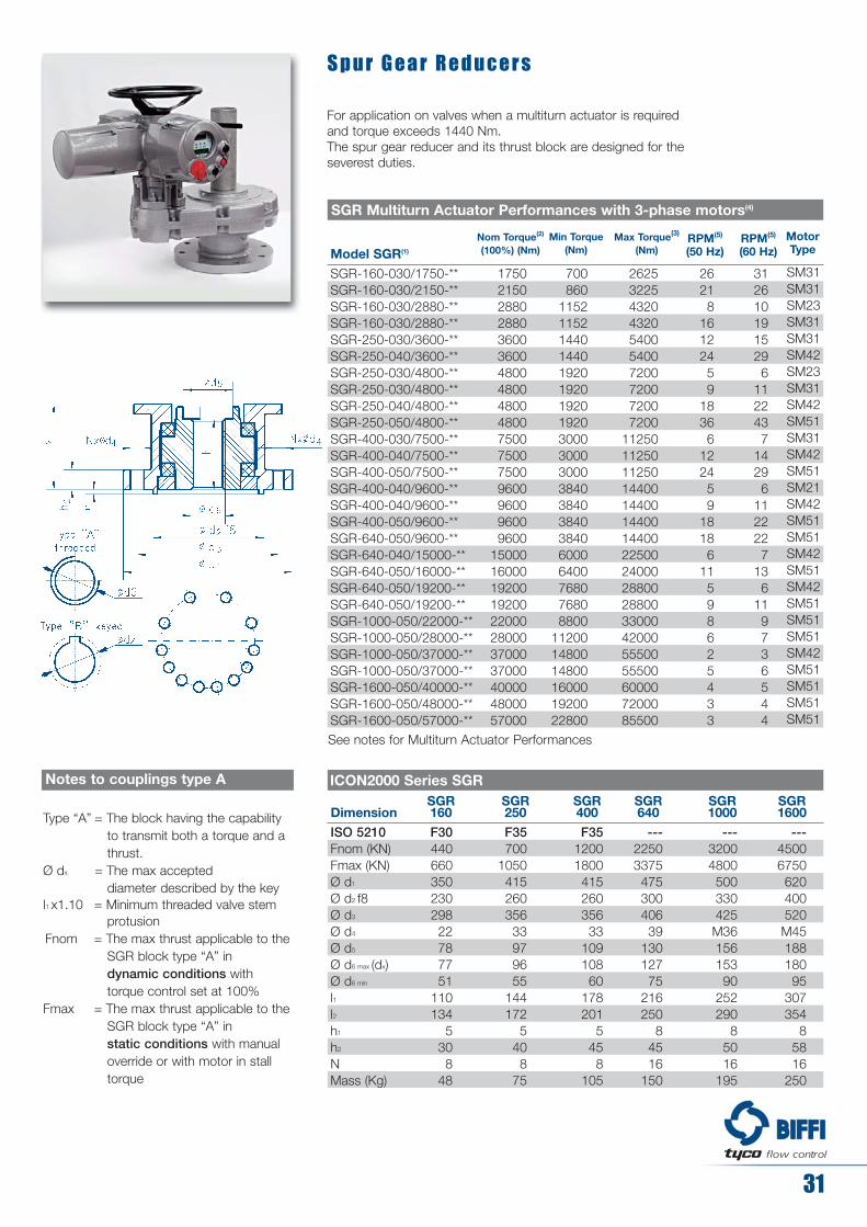
DimensionSGR160
SGR250
SGR400
SGR640
SGR1000
SGR1600
ISO 5210Fnom (KN)Fmax (KN)Ø d1
Ø d2 f8Ø d3
Ø d4
Ø d5
Ø d6 max (dx)Ø d6 min
l1l2h1
h2
NMass (Kg)
F3044066035023029822787751
110134
5308
48
F35700
105041526035633979655
144172
5408
75
F351200180041526035633
10910860
178201
5458
105
---2250337547530040639
13012775
216250
84516
150
---32004800500330425M3615615390
252290
85016
195
---45006750620400520M4518818095
307354
85816
250
ICON2000 Series SGRNotes to couplings type A
Type “A” = The block having the capabilityto transmit both a torque and a thrust.
Ø dx = The max accepted diameter described by the key
l1 x1.10 = Minimum threaded valve stem protusion
Fnom = The max thrust applicable to theSGR block type “A” in dynamic conditions with torque control set at 100%
Fmax = The max thrust applicable to theSGR block type “A” in static conditions with manual override or with motor in stall torque
Model SGR(1)
SGR-160-030/1750-**SGR-160-030/2150-**SGR-160-030/2880-**SGR-160-030/2880-**SGR-250-030/3600-**SGR-250-040/3600-**SGR-250-030/4800-**SGR-250-030/4800-**SGR-250-040/4800-**SGR-250-050/4800-**SGR-400-030/7500-**SGR-400-040/7500-**SGR-400-050/7500-**SGR-400-040/9600-**SGR-400-040/9600-**SGR-400-050/9600-**SGR-640-050/9600-**SGR-640-040/15000-**SGR-640-050/16000-**SGR-640-050/19200-**SGR-640-050/19200-**SGR-1000-050/22000-**SGR-1000-050/28000-**SGR-1000-050/37000-**SGR-1000-050/37000-**SGR-1600-050/40000-**SGR-1600-050/48000-**SGR-1600-050/57000-**
17502150288028803600360048004800480048007500750075009600960096009600
1500016000192001920022000280003700037000400004800057000
700860
11521152144014401920192019201920300030003000384038403840384060006400768076808800
112001480014800160001920022800
2625322543204320540054007200720072007200
112501125011250144001440014400144002250024000288002880033000420005550055500600007200085500
26218
16122459
18366
122459
18186
11598625433
3126101915296
1122437
14296
1122227
136
119736544
SGR Multiturn Actuator Performances with 3-phase motors(4)
S p u r G e a r R e d u c e r s
For application on valves when a multiturn actuator is required and torque exceeds 1440 Nm.The spur gear reducer and its thrust block are designed for the severest duties.
Nom Torque(2)
(100%) (Nm)Max Torque(3)
(Nm)RPM(5)
(50 Hz)Min Torque
(Nm)RPM(5)
(60 Hz)
See notes for Multiturn Actuator Performances
31
!@#$ flow control
SM31SM31SM23SM31SM31SM42SM23SM31SM42SM51SM31SM42SM51SM21SM42SM51SM51SM42SM51SM42SM51SM51SM51SM42SM51SM51SM51SM51
Motor Type

Model A a1 a2 B b1 b2 ØC F H h1 h2 h3Mass
Kg
SGR-160-030SGR-250-030SGR-250-040SGR-250-050SGR-400-030SGR-400-040SGR-400-050SGR-640-040SGR-640-050SGR-1000-050SGR-1600-050
859927983
1036980
103610891098115112641560
399399445508399455508455508508508
270319319319373373373405405456602
a3190227227227208208208237238300450
625625690775625690755690755755755
313313318363313318363318363363363
312312372392312372392372392392392
400500500500500500500600600600600
251345310310383383383460460500564
F30 F35F35F35F35F35F35SPEC.
SPEC.
SPEC.
SPEC.
617684724684736776866838928968
1040
231315280280356356356418418458522
380380420380380420510420510510510
127154170194232248272 288312417752
SGR/ICON2000 Series Overall Dimensions
32
!@#$ flow control
Standard cable entries:a = 1” NPTb = 1 1/2” NPT
Dep
endi
ng o
n va
lve
stro
ke
Lever Position Detail
AUTO
MANUAL

33
!@#$ flow control
Model A a1 a2 B b1 b2 ØC H h1 h2 h3Mass
Kg
SGR-160-030SGR-250-030SGR-250-040SGR-250-050SGR-400-030SGR-400-040SGR-400-050SGR-640-040SGR-640-050SGR-1000-050SGR-1600-050
814880942
1012934995
10641057112412401535
354354416484354415484415482484483
270319319319373373373405405456602
a3190227227227208208208238238300450
679678742809678741809743807809808
300302310334302311334311335334334
379376432475376430475432472475474
300300400500300400500400500500500
251345310310383383383460460500564
717748828977817884
1033947
109111321196
231315280280356356356418418458522
486448528677461528677528673674674
135162178202240256280 296320425760
SGR/ICON2000 Series Overall Dimensions (with reduced manual override)
Standard cable entries:a = 1” NPTb = 1 1/2” NPT
Dep
endi
ng o
n va
lve
stro
ke
View from X
Lever Position Detail
AUTO
MANUAL
ISO 5210 “F” size (see page 31)

34
!@#$ flow control
Model ISO5211 Ø d1 Ø d3 Ø d4 N° H h2 Ø d7 Ø dx
WGR-100WGR-200WGR-400WGR-800WGR-800WGR-1600WGR-1600WGR-3200WGR-3200WGR-6300
F14F16F16F25F30F25F30F30F35F40
175210210300350300350350415475
140165165254298254298298356406
Ø Pin16161620202020202030
M16M20M20M16M20M16M20M20M30M36
4448888888
100105105115115140140165165250
16202020202430303036
4265659090
103103120120170
517676
104104120120139139194
ICON2000 Series WGR
Insert Bush
d7 Max Stem Acceptance
Notes
1. Insert bush supplied by BIFFI with unmachined bore. Machining of boreupon request
2. Fixing bolts or rods supplied by BIFFIonly on request, minimum material classrequired 8.8 UNI37409, ASTM A320-L7
3. Any other coupling can be supplied onrequest
4. Flanges for models WGR-800, 1600 and3200 have double PCD.
W o r m G e a r R e d u c e r s f o r Q u a r t e r T u r n V a l v e s
For application on any type of quarter turn valves (ball, butterfly, plug...).The worm gear is designed to meet AWWA C-540 and other major standards.

35
!@#$ flow control
Model A a1 a2 B b1 b2 ØC F H h1 h2Mass
Kg
WGR-100-010WGR-200-010WGR-400-010WGR-800-020WGR-1600-020WGR-3200-020WGR-3200-030WGR-6300-020WGR-6300-030WGR-6300-040
519560662820871943989
105310991163
90123123150160250250305305305
139147269302343325325380380380
a3290290270368368368414368414478
421466491562594700743820844886
273273273283283283313283313318
292292292300300300312300312372
300300300500500500600500600720
D86
119119130162243243303303303
F14F16 F16F25F25/F30
F30/F35
F30/F35
F40F40F40
387381390397412427453472498596
62535360759090
135135135
115125125135165180180270270270
40526985
130166174509517527
WGR/ICON2000 Series Overall Dimensions
Standard cable entries:a = 1” NPTb = 1 1/2” NPT
Lever Position Detail
AUTO
MANUAL

36
!@#$ flow control
Model WGR(1)Nom Torque(2)(100%)
(Nm)Min Torque
(Nm)Op. Time/90°
(secs at 50 Hz)Op. Time/90°
(secs at 60 Hz)Max Torque(3)
(Nm)
WGR-100-010/1000-**WGR-100-010/1000-**WGR-100-010/1000-**WGR-100-010/1000-**WGR-100-010/1000-**WGR-100-010/1000-**WGR-200-010/2000-**WGR-200-010/2000-**WGR-200-010/2000-**WGR-200-010/2000-**WGR-200-010/2000-**WGR-200-010/2000-**WGR-200-010/2000-**WGR-400-010/4000-**WGR-400-010/4000-**WGR-400-010/4000-**WGR-400-010/4000-**WGR-400-010/4000-**WGR-400-010/4000-**WGR-400-010/4000-**WGR-800-020/8000-**WGR-800-020/8000-**WGR-800-020/8000-**WGR-800-020/8000-**WGR-800-020/8000-**WGR-800-020/8000-**WGR-800-020/8000-**WGR-1600-020/16000-**WGR-1600-020/16000-**WGR-1600-020/16000-**WGR-1600-020/16000-**WGR-1600-020/16000-**WGR-1600-020/16000-**WGR-1600-020/16000-**WGR-3200-020/32000-**WGR-3200-020/32000-**WGR-3200-020/32000-**WGR-3200-020/32000-**WGR-3200-020/32000-**WGR-3200-020/32000-**WGR-3200-030/32000-**WGR-6300-020/63000-**WGR-6300-020/63000-**WGR-6300-020/63000-**WGR-6300-020/63000-**WGR-6300-030/63000-**WGR-6300-040/63000-**
WGR-100/330-**WGR-100/330-**WGR-100/330-**WGR-100/330-**WGR-100/330-**WGR-100/330-**
100010001000100010001000200020002000200020002000200040004000400040004000400040008000800080008000800080008000
1600016000160001600016000160001600032000320003200032000320003200032000630006300063000630006300063000
330330330330330330
400400400400400400800800800800800800800
160016001600160016001600160032003200320032003200320032006400640064006400640064006400
12800128001280012800128001280012800252002520025200252002520025200
132132132132132132
52352617139
10469523526179
118785939292010
20813910469523517
389259194130976532
5193892591951306535
5834382921468040
52352617139
634231211610
125836342312110
1551037852392613
25016712583634221
4663112331551177839
6234673112331567842
7005253501759648
634231211610
15001500150015001500150030003000300030003000300030006000600060006000600060006000
120001200012000120001200012000120002400024000240002400024000240002400048000480004800048000480004800048000945009450094500945009450094500
500500500500500500
WGR-Quarter turn Actuator Performances with 3-phase motors(4)
Motor Type
SM10SM11SM12SM13SM14SM15SM10SM11SM12SM13SM14SM15SM16SM10SM11SM12SM13SM14SM15SM16SM12SM13SM14SM15SM21SM22SM23SM12SM13SM14SM15SM21SM22SM23SM13SM14SM15SM21SM22SM23SM31SM15SM21SM22SM23SM31SM42
SM00SM01SM10SM11SM04SM05
See notes for Multiturn Actuator performances

E l g a
Scotch-yoke reducer for application on valves requiring high torques at stroke limits(Open/Close). Also used on quarter-turn valves when very high torques are required.
37
!@#$ flow control
Model(1)
ELGA-14KR-020/94000-**ELGA-14KR-020/94000-**ELGA-14KR-020/94000-**ELGA-14KR-020/94000-**ELGA-14KR-020/94000-**ELGA-14KR-030/94000-**ELGA-14KR-040/94000-**ELGA-18KR-020/133000-**ELGA-18KR-020/133000-**ELGA-18KR-020/133000-**ELGA-18KR-020/133000-**ELGA-18KR-020/133000-**ELGA-18KR-030/133000-**ELGA-18KR-040/133000-**ELGA-32KR-030/266000-**ELGA-32KR-030/266000-**ELGA-32KR-030/266000-**ELGA-32KR-030/266000-**ELGA-32KR-040/266000-**ELGA-32KR-050/266000-**ELGA-50KR-030/334000-**ELGA-50KR-030/334000-**ELGA-50KR-030/334000-**ELGA-50KR-030/334000-**ELGA-50KR-040/334000-**ELGA-50KR-050/334000-**
5430054300543005430054300543005430077000770007700077000770007700077000
156000156000156000156000156000156000197000197000197000197000197000197000
82000820008200082000820008200082000
116000116000116000116000116000116000116000238000238000238000238000238000238000300000300000300000300000300000300000
94000940009400094000940009400094000
133000133000133000133000133000133000133000266000266000266000266000266000266000334000334000334000334000334000334000
141000141000141000141000141000141000141000199500199500199500199500199500199500199500399000399000399000399000399000399000501000501000501000501000501000501000
8655774332881446942
133088766544322213357
127295463631818175
128096064032015265
7214813612401205835
110873955436918511148
106079553026515163
106780053326712754
ICON-020/180-24(29)ICON-020/180-36(43)ICON-020/180-48(58)ICON-020/180-72(86)ICON-020/180-144(173)ICON-030/360-144(173)ICON-040/720-144(173)ICON-020/180-24(29)ICON-020/180-36(43)ICON-020/180-48(58)ICON-020/180-72(86)ICON-020/180-144(173)ICON-030/360-144(173)ICON-040/720-144(173)ICON-030/360-36(43)ICON-030/360-48(58)ICON-030/360-72(86)ICON-030/360-144(173)ICON-040/720-144(173)ICON-050/1440-144(173)ICON-030/360-36(43)ICON-030/360-48(58)ICON-030/360-72(86)ICON-030/360-144(173)ICON-040/720-144(173)ICON-050/1440-144(173)
ELGA Actuator Performances with 3-phase motors(4)
Nom. Torque(2) (100%) (Nm) Max Torque(3)
(Nm)Break To Open Running End to open
Op. Time/90°
(secs at
50 Hz)
Op. Time/90°
(secs at
60 Hz)
ICON2000
Model
Motor
Type
SM14SM15SM21SM22SM23SM31SM42SM14SM15SM21SM22SM23SM31SM42SM22SM30SM23SM31SM42SM51SM22SM30SM23SM31SM42SM51
Motor Power
(KW) at 50Hz
Motor Power
(KW) at 60Hz
0.2860.3670.5260.7891.4703.3685.8180.2860.3670.5260.7891.4703.3685.8180.7891.1231.4703.3685.818
11.6360.7891.1231.4703.3685.818
11.636
0.3430.4400.6310.9471.7644.0426.9820.3430.4400.6310.9471.7644.0426.9820.9471.3481.7644.0426.982
13.9630.9471.3481.7644.0426.982
13.963
Notes
1. The ** are to be replaced by operatingtime value at selected frequency (50 or 60 Hz)
2. Nominal output torque settable from 40%(minimum torque) to 100% of indicatedvalue
3. Theoric max output torque. The actualmax output torque is a function of speedand motor power supply and may varyfrom 1.3 to 2 times nominal output torque
4. The performances below are referred toON/OFF S2-15' or INCHING S4-25%-60starts/hour duties (IEC34-1)

38
!@#$ flow control
Notes
1. Insert bush supplied by BIFFI with unmachined bore. Machining of boreupon request
2. Different values of flange dimensions canbe supplied on request
3. Female spigot supplied as a standard. Male spigot supplied onrequest. Model 1.5K without spigot
4. Fixing bolts or rods supplied byBIFFI only on request, minimummaterial class required 8.8UNI37409, ASTM A320-L7
ModelISO
5211 (2) Ø d1 Ø d3 Ø d4 (4) N Hh2 Ø d7 Ø dx
1418325080
F48F60F60
SPECIALSPECIAL
580680780800890
Ø d2 (3)250290290315370
483603603698813
M36M36M36M36M42
1220202424
h1 (3)1012121010
340350400430585
2932323237
Ø 160Ø 160Ø 180Ø 200Ø 250
Ø 185Ø 185Ø 206Ø 226Ø 282
ICON2000 Series Elga
With Insert Bush One Piece Bush
Ø d7 Ø dx
Ø 200Ø 220Ø 230Ø 255Ø 300
Ø 228Ø 250Ø 260Ø 285Ø 338
d7 Max Stem Acceptance

Model A a1 a2 B b1 b2 ØC F H h1 h2Mass
Kg
14KR-02014KR-03014KR-04018KR-02018KR-03018KR-04032KR-03032KR-04032KR-05050KR-03050KR-04050KR-050
161916531712172717611820196420642185234024392599
536536536583583583663663663710710710
778778778839839839
112411641244129113311411
a3305339398305339398339398478339398478
772793835852873915863
10051049100310451089
283313318283313318313318363313318363
300312372300312372312372392312372392
500600720500600720600720860600720860
D200200200230230230270270270300300300
F48F48F48F60F60F60F60F60F60SPEC.
SPEC.
SPEC.
463476627542595656632693750633694751
166166166195195195232232232233233233
320320320383383383464464464561561561
650660670800810820960970980
118011902000
ELGA/ICON2000 Series Overall Dimensions
39
!@#$ flow control
Standard cable entries:a = 1” NPTb = 1 1/2” NPT
Lever Position Detail
AUTO
MANUAL
40
!@#$ flow control
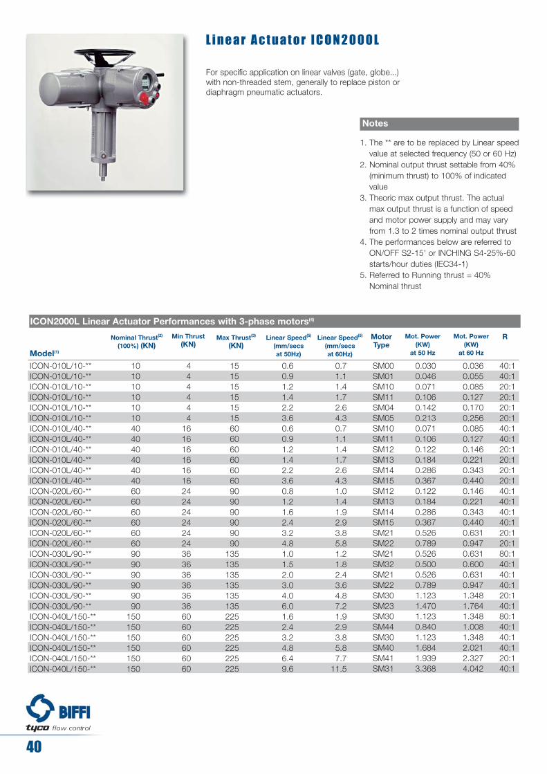
L i n e a r A c t u a t o r I C O N 2 0 0 0 L
For specific application on linear valves (gate, globe...) with non-threaded stem, generally to replace piston or diaphragm pneumatic actuators.
Model(1)
Nominal Thrust(2)
(100%) (KN)Max Thrust(3)
(KN)Mot. Power
(KW) at 50 Hz
Mot. Power(KW)
at 60 Hz
Linear Speed(5)
(mm/secs at 50Hz)
Linear Speed(5)
(mm/secs at 60Hz)
ICON-010L/10-**ICON-010L/10-**ICON-010L/10-**ICON-010L/10-**ICON-010L/10-**ICON-010L/10-**ICON-010L/40-**ICON-010L/40-**ICON-010L/40-**ICON-010L/40-**ICON-010L/40-**ICON-010L/40-**ICON-020L/60-**ICON-020L/60-**ICON-020L/60-**ICON-020L/60-**ICON-020L/60-**ICON-020L/60-**ICON-030L/90-**ICON-030L/90-**ICON-030L/90-**ICON-030L/90-**ICON-030L/90-**ICON-030L/90-**ICON-040L/150-**ICON-040L/150-**ICON-040L/150-**ICON-040L/150-**ICON-040L/150-**ICON-040L/150-**
101010101010404040404040606060606060909090909090
150150150150150150
151515151515606060606060909090909090
135135135135135135225225225225225225
Min Thrust(KN)
444444
161616161616242424242424363636363636606060606060
0.60.91.21.42.23.60.60.91.21.42.23.60.81.21.62.43.24.81.01.52.03.04.06.01.62.43.24.86.49.6
0.71.11.41.72.64.30.71.11.41.72.64.31.01.41.92.93.85.81.21.82.43.64.87.21.92.93.85.87.7
11.5
ICON2000L Linear Actuator Performances with 3-phase motors(4)
RMotor Type
SM00SM01SM10SM11SM04SM05SM10SM11SM12SM13SM14SM15SM12SM13SM14SM15SM21SM22SM21SM32SM21SM22SM30SM23SM30SM44SM30SM40SM41SM31
40:140:120:120:120:120:140:140:120:120:120:120:140:140:140:140:120:120:180:140:140:140:120:140:180:140:140:140:120:140:1
0.0300.0460.0710.1060.1420.2130.0710.1060.1220.1840.2860.3670.1220.1840.2860.3670.5260.7890.5260.5000.5260.7891.1231.4701.1230.8401.1231.6841.9393.368
0.0360.0550.0850.1270.1700.2560.0850.1270.1460.2210.3430.4400.1460.2210.3430.4400.6310.9470.6310.6000.6310.9471.3481.7641.3481.0081.3482.0212.3274.042
Notes
1. The ** are to be replaced by Linear speedvalue at selected frequency (50 or 60 Hz)
2. Nominal output thrust settable from 40%(minimum thrust) to 100% of indicatedvalue
3. Theoric max output thrust. The actualmax output thrust is a function of speedand motor power supply and may varyfrom 1.3 to 2 times nominal output thrust
4. The performances below are referred toON/OFF S2-15' or INCHING S4-25%-60starts/hour duties (IEC34-1)
5. Referred to Running thrust = 40%Nominal thrust

41
!@#$ flow control
Model 010L 020L 030L 040L
ISO 5210/DIN3358Fnom (KN)Fmax (KN)Ø d1
Ø d2 f8Ø d3
Ø d4
Ø d8 (left)
h1
h2
l7l2l4NS(Max stroke)
Mass (Kg)
F104060
12570
102M10
M20x1,5 3
1526525354
10010
F146090
175100140M16
M36x3 4
2437555604
16018
F1480
135175100140M16
M36x3 4
2448055604
20022
F16150225210130165M20
M42x3 4
3058065804
30028
ICON2000 Series Linear
Notes
1. The stem is drawn in fully retracted position.
2. The stem end (Ø d8) is left hand thread3. Only axial loads are permitted4. Fnom is the maximum thrust applicable to
the linear thrust block in dynamicconditions with torque control set at 100%.Fmax is the maximum thrust applicable tothe linear thrust block in static conditionswith manual override or with motor in stalltorque

42
!@#$ flow control
Model(1)
Nominal Thrust(2)
(100%) (KN)Max Thrust(3)
(KN)Mot. Power
(KW) at 50 Hz
Mot. Power(KW)
at 60 Hz
Linear Speed(5)
(mm/secs at 50Hz)
Linear Speed(5)
(mm/secs at 60Hz)
ICON-010L/10-**ICON-010L/10-**ICON-010L/10-**ICON-010L/10-**ICON-010L/10-**ICON-010L/10-**ICON-010L/40-**ICON-010L/40-**ICON-010L/40-**ICON-010L/40-**ICON-010L/40-**ICON-010L/40-**ICON-020L/60-**ICON-020L/60-**ICON-020L/60-**ICON-020L/60-**ICON-020L/60-**ICON-020L/60-**ICON-030L/90-**ICON-030L/90-**ICON-030L/90-**ICON-030L/90-**ICON-040L/150-**ICON-040L/150-**ICON-040L/150-**
10101010101040404040404060606060606090909090
150150150
151515151515606060606060909090909090
135135135135225225225
Min Thrust(KN)
444444
16161616161624242424242436363636606060
0.60.91.21.42.23.60.60.91.21.42.23.60.81.21.62.43.24.82.03.04.06.03.24.89.6
0.71.11.41.72.64.30.71.11.41.72.64.31.01.41.92.93.85.82.43.64.87.23.85.8
11.5
ICON2000L Linear Actuator Performances with 3-phase motors(4)
RMotor Type
TM00TM01TM10TM11TM04TM05TM10TM11TM12TM13TM14TM15TM12TM13TM14TM15TM21TM22TM21TM22TM30TM23TM30TM40TM31
40:140:120:120:120:120:140:140:120:120:120:120:140:140:140:140:120:120:140:140:120:140:140:140:140:1
0.0300.0460.0710.1060.1420.2130.0710.1060.1220.1840.2860.3670.1220.1840.2860.3670.5260.7890.5260.7891.1231.4701.1231.6843.368
0.0360.0550.0850.1270.1700.2560.0850.1270.1460.2210.3430.4400.1460.2210.3430.4400.6310.9470.6310.9471.3481.7641.3482.0214.042
Notes
1. The ** are to be replaced by Linear speedvalue at selected frequency (50 or 60 Hz)
2. Nominal output thrust settable from 40%(minimum thrust) to 100% of indicatedvalue
3. Theoric max output thrust. The actualmax output thrust is a function of speedand motor power supply and may varyfrom 1.3 to 2 times nominal output thrust
4. The performances below are referred toON/OFF S2-30' or INCHING S4-25%-600starts/hour duties (IEC34-1)
5. Referred to Running thrust = 40%Nominal thrust
6. Ambient temperature from -55°C to 65°C

For any further information you may require please contact Biffi Sales office; tel. ++39-0523.944411, fax ++39-0523.943923, e-mail: [email protected]
43
!@#$ flow controlBiffi reserves the right to modify contents without notice.

Biffi Italia s.r.l.Headquarters, Sales department, 29017 Fiorenzuola d’Arda - Italy tel. +39 0523 944411 fax +39 0523 943923 e-mail [email protected]
website: www.biffi.it
ICON20
00-B
U-E Re
v. 6 F
eb 20
08