image analysis report - clemex analysis report # 171 grain size characterization of titanium ......
TRANSCRIPT

Report # 171
Page 2 of 4
Sample Description
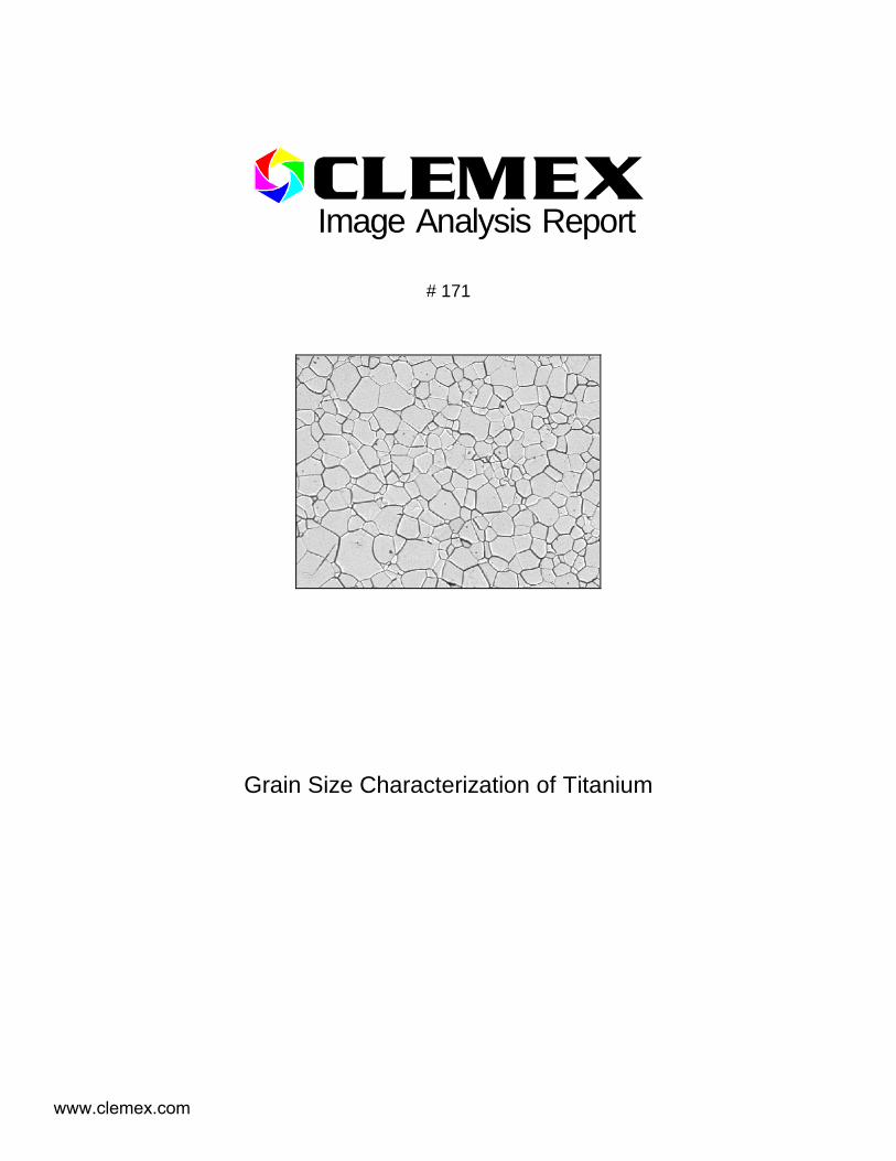
Three unmounted samples of electro-polished titanium.
Purpose of Analysis
Demonstrate the ability of the image analyzer to discriminate and measure all grains in the field of view.
Equipment Used
Image Analysis System: Clemex Vision Software Microscope: Nikon (2.5, 5.0, 10, 20, 50, 100X objectives) Stage: Marzhauser EK8B-S1 Camera: Sony XC-77CE 1:1 (728X574) B&W
Procedures
Magnification ranged from 100X to 500X. The procedures described here were performed at 200X for a calibration factor of 0.8197 µm/pixel. Fifteen fields were analyzed for each sample. Each field measured 280 752.49 µm2.
The original image (cover page) was improved by a Gray Opening and a Gray Delineate. Figure 1a shows a gray transformation (Top Hat on Black) that isolates all black and thin objects (they appear white). Binarization by Gray Threshold was performed on the transformed gray image. Figure 1b shows the resulting red bitplane.
Artifacts were removed from the red bitplane using binary operations (Trap, Boolean) and Object Transfer by Limits (Length, Aspect Ratio). Discarded objects were sent to the green bitplane, as shown in Figure 2a.
The grain outline was then inverted into the green bitplane to obtain complete grains. A binary operation (Erode) applied on the green bitplane helped to separate typical grains. Meanwhile, roughly shaped grains were isolated in the red bitplane using a Roughness based Object Transfer. Red objects that were in contact with one another were treated using the more aggressive Circular Opening function. The newly separated objects were then isolated in the pink bitplane. The remaining red objects (the roughest) were then subdivided
www.clemex.com

Report # 171
Page 3 of 4
according to their convexity (Separate). Figure 2b shows these three categories (green, pink and red).
As shown in Figure 3a, green, pink and red bitplanes were recombined (in red) and spread out, maintaining a 2 pixels gap between grains (Zone). The Figure 3b shows the grain boundary network overlaid against the original image.
Grain size measurements (ASTM E 112) by objects and by fields were then performed. A Length measurement was also performed on each object. Figure 4 shows a grain size distribution.
The most significant image modifications and final results are as follows:
Figure 1a: Black Top Hat of the improved original image (cover page).
Figure 1b: Binarization by Thresholding of the preceding gray image.
Figure 2a: Artifacts (in green) are removed (Trap, Boolean) from the red bitplane.
Figure 2b: Roughest objects are in red and will be subdivided according to their convexity.
Figure 3a: Bitplanes are recombined and spread out, maintaining a 2 pixels gap between grains (Zone).
Figure 3b: Grain boundary network overlaid against the original image.
Figure 4: ASTM E 112 grain size distribution.
www.clemex.com

Report # 171
Page 4 of 4
Results Summary
Grain Size by object
Grain Size by field
Length by object (µm)
Minimum Rating 4.13 7.19 Minimum 6.7 Maximum Rating 12.16 7.52 Maximum 122.1
Mean Rating* 7.78 7.37 Average 34.2 Standard Deviation 17.6
*The logarithm is removed before the mean rating is calculated, then it is added to the result.
Discussion
The image analysis system can discriminate grains and, produce size measurement distributions.
At first, binarizing the original image appeared difficult because of the uneven gray intensity of the samples. This problem was easily overcome by applying a gray filter (Top Hat on Black).
One of the sample had very small grains and had to be analyzed at 500X. This sample appeared to have an uneven surface. A Multilayer Grab instruction was used to obtain an image1 in sharp focus despite the fact that not all features were in the same focal plane.
Another sample had some uneven dark grains. A Gray Opening was applied to spread the pixels in the middle of the gray level range over the white areas. This resulted in a more uniform image although some dark grains remained. After applying a Top Hat on Black, a Watershed gray/binary transformation produced a binary approximation of the boundaries. The watershed based boundaries were combined with the usual boundary detection to discriminate some extra grain boundaries.
During the analysis, some small cells were inadvertently “lost” during binarization or, eliminated by a filter (Trap, Opening, Erode). It also occurred that cells that were in contact with one another were not separated. These limitations lead to a slight overestimation of cell size.
It also occurred that large and roughly shaped cells were subdivided into several cells by the Separate instruction. This tended to counteract the overestimation problem discussed above such that final results were not significantly influenced by occasional improper detections.
Results are reproducible.
1 A complete exemple is presented in Appendix A.
www.clemex.com

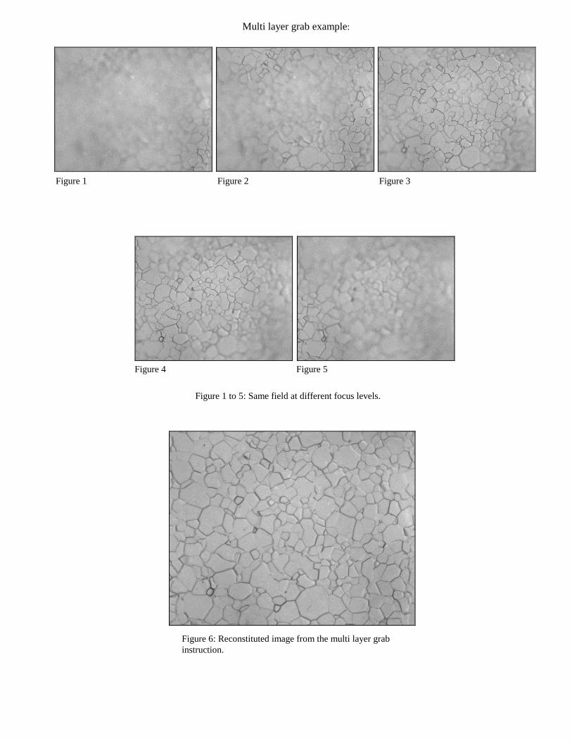
Multi layer grab example:
Figure 1 Figure 2 Figure 3
Figure 4
Figure 1 to 5: Same field at different focus levels.
Figure 5
Figure 6: Reconstituted image from the multi layer grab instruction.