im116e frame 9e
TRANSCRIPT

215 Clinton Road. New Hartford, NY 13413 Tel: 315-768-4855 Fax: 315-768-4941 Email: [email protected]
INSTRUCTION MANUAL IM-116 For Gas Turbine Tensioned Studs and Nuts
Fr.9E Turbine to 9A3 ELIN Generator GE358A7202P022 The Riverhawk Company reserves the right to make changes updating this document without dissemination or notice. The latest revision level may be obtained by contacting Riverhawk Company directly or visit our website at www.riverhawk.com
VENDOR SUPPLIED DRAWINGGE NOT TO REVISE. GE REVISION LEVEL IS AS SHOWN ON THIS APPLIQUE.
THIS DOCUMENT IS FILED UNDER THE GE DR AWING NUMBERTHIS DOCUMENT SHALL BE REVISED IN ITS ENTIRETY. ALL SH EETS OF THIS DOCUMENT
ARE TH E SAME REV ISION LEVEL AS INDICA TED IN THIS V ENDOR SUPPLIED DRAWING A PPLIQUE
FIRST MADE FOR: ___ OF ___
GE Power Generation
ISSUED
CH ECKEDG E SIGNATURES DATE
E GE DRAWING N UMBER REV
GENERAL ELECTRIC COMPANYSc henectady, NY
373A4028
GE ALTERATION NOTICE NUMBER
REVIS ION LETTER

Instruction Manual IM-116 For Gas Turbine Tensioned Studs & Nuts
2
215 Clinton Road. New Hartford, NY 13413 Tel: 315-768-4855 Fax: 315-768-4941 Email: [email protected]
373A4028 E REV .
SH .FIRST MADE FOR:
GE DRAWING NUMBER
Table of Contents
Section Description Page Number
1.0 Cautions and Safety Warnings 3
2.0 Scope 4
3.0 Quick Check-List 5
4.0 General Preparations 8
5.0 Hardware Set Preparations 9
6.0 Stud and Nut Assembly 11
7.0 Assembly of Hydraulic Tensioner Equipment 12
8.0 Assembly of Tensioner on Stud 13
9.0 Stud Pulling and Tensioning 15
10.0 Thread Locking 16
11.0 Stud/Nut Removal 17
12.0 Storage 18
13.0 Frequent Asked Questions 19
14.0 Revision History 22

Instruction Manual IM-116 For Gas Turbine Tensioned Studs & Nuts
3
215 Clinton Road. New Hartford, NY 13413 Tel: 315-768-4855 Fax: 315-768-4941 Email: [email protected]
373A4028 E REV .
SH .FIRST MADE FOR:
GE DRAWING NUMBER
1.0 Cautions and Safety Warnings
CAUTION Personal injury and equipment damage can occur if the puller screw is not securely engaged with the tapered thread of the stud. Proper engagement is achieved when the puller screw is tight in the stud and the Tensioner Assembly is free to rotate.
WARNING The safety cage MUST be in place and hands kept out of designated areas at all times when the tensioner is pressurized otherwise personal injury can occur.
CAUTION DO NOT EXCEED THE MAXIMUM PRESSURE VIBROSCRIBED ON THE PULLER BODY. Excessive pressure can damage the stud and the puller screw.
WARNING Fire Hazard! DO NOT heat when the puller assembly is in place. Personal injury or equipment damage may occur. Use of an Oxy-Acetylene torch is not recommended.
NOTICE Do not use more thread locking compound than specified or the nut may be VERY difficult to remove at disassembly.
CAUTION DO NOT EXCEED THE MAXIMUM PRESSURE VIBROSCRIBED ON THE PULLER BODY. Excessive pressure can damage the stud and puller screw Note: Before threading the puller screw into the stud, carefully check the cleanliness of both the stud's and the puller screw's conical threads. Apply a light coat of clean turbine oil or a spray lubricant to the puller screw. Do not use “Never Seize” on the conical threads. This procedure will ease assembly and assure positive mating of the threads before tightening.
Instruction Manual IM-116 For Gas Turbine Tensioned Studs & Nuts
4
215 Clinton Road. New Hartford, NY 13413 Tel: 315-768-4855 Fax: 315-768-4941 Email: [email protected]
373A4028 E REV .
SH .FIRST MADE FOR:
GE DRAWING NUMBER
2.0 Scope This document describes the procedure to be used to install studs and nuts supplied by Riverhawk Company in the flanges at the turbine/coupling and coupling/generator connections. This hardware is depicted on the following drawings These drawings as well as the tooling drawings form a part of this manual. HF-0813

Instruction Manual IM-116 For Gas Turbine Tensioned Studs & Nuts
5
215 Clinton Road. New Hartford, NY 13413 Tel: 315-768-4855 Fax: 315-768-4941 Email: [email protected]
373A4028 E REV .
SH .FIRST MADE FOR:
GE DRAWING NUMBER
3.0 Quick Checklist The following checklist is intended as a summary of the steps needed to use the Riverhawk-supplied equipment. New personnel or those experienced personnel who have not used the Riverhawk equipment recently are encouraged to read the entire manual.
EQUIPMENT INSPECTION
□ • Check oil level in hydraulic pump.
□ • Check air pressure at 80 psi [5.5 bar] minimum. (For air-driven pumps)
□ • Check hydraulic hose for damage.
□ • Test pump.
□ • Inspect tensioner for any damage.
NUT AND STUD PREPARATION
□ • Inspect stud and nuts for any damage.
□ • Measure stud length.
□ • Clean the studs and nuts.
□ • Install studs and nuts (off-center) into the flange.
□ • Set stick-out dimension on the coupling side of the flange.
□ • Hand tighten all studs.
□ • Verify stick-out measurement (VERY IMPORTANT)

Instruction Manual IM-116 For Gas Turbine Tensioned Studs & Nuts
6
215 Clinton Road. New Hartford, NY 13413 Tel: 315-768-4855 Fax: 315-768-4941 Email: [email protected]
373A4028 E REV .
SH .FIRST MADE FOR:
GE DRAWING NUMBER
Tensioning (Bolt installation)
□ • Match the tensioner setup to the flange joint.
□ • Apply a light coat of clean turbine oil or spray lubricant to the puller screw. DO NOT USE “NEVER SEIZE” ON THE CONICAL THREADS.
□ • Slide spanner ring over the puller screw.
□ • Mount the tensioner on the stud in flange.
□ • Install spanner ring onto nut.
□ • Insert 1/2” hex Allen wrench into the back side of the stud.
□ • Tighten the puller screw.
□ • Back off puller screw 1/2 turn.
□ • Retighten the puller screw and leave tight. DO NOT BACK OFF PULLER SCREW.
□ • Bleed the tensioner. Do NOT bleed tensioner off of a stud! Damage to the tool will result!
□ • Tension to 50%. Consult manual for correct pressure.
□ • Use the pin wrench in spanner ring to tighten nut.
□ • Release pressure, move to next stud in pattern.
□ • Repeat above steps at final pressure.
□ • Measure final stud length and record on stretch datasheets. Calculate stretch.
□ • Torque nuts' set screws.
Instruction Manual IM-116 For Gas Turbine Tensioned Studs & Nuts
7
215 Clinton Road. New Hartford, NY 13413 Tel: 315-768-4855 Fax: 315-768-4941 Email: [email protected]
373A4028 E REV .
SH .FIRST MADE FOR:
GE DRAWING NUMBER
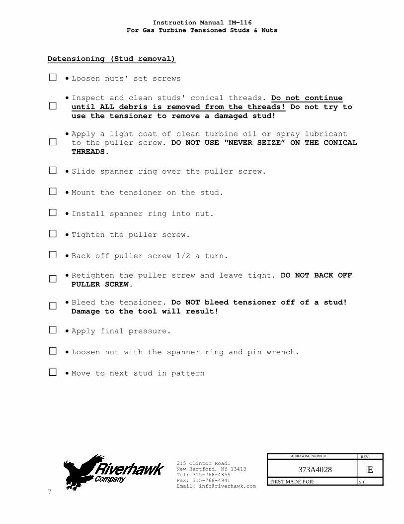
Detensioning (Stud removal)
□ • Loosen nuts' set screws
□ • Inspect and clean studs' conical threads. Do not continue until ALL debris is removed from the threads! Do not try to use the tensioner to remove a damaged stud!
□ • Apply a light coat of clean turbine oil or spray lubricant to the puller screw. DO NOT USE “NEVER SEIZE” ON THE CONICAL THREADS.
□ • Slide spanner ring over the puller screw.
□ • Mount the tensioner on the stud.
□ • Install spanner ring into nut.
□ • Tighten the puller screw.
□ • Back off puller screw 1/2 a turn.
□ • Retighten the puller screw and leave tight. DO NOT BACK OFF PULLER SCREW.
□ • Bleed the tensioner. Do NOT bleed tensioner off of a stud! Damage to the tool will result!
□ • Apply final pressure.
□ • Loosen nut with the spanner ring and pin wrench.
□ • Move to next stud in pattern

Instruction Manual IM-116 For Gas Turbine Tensioned Studs & Nuts
8
215 Clinton Road. New Hartford, NY 13413 Tel: 315-768-4855 Fax: 315-768-4941 Email: [email protected]
373A4028 E REV .
SH .FIRST MADE FOR:
GE DRAWING NUMBER
4.0 General Preparations Read and understand all instructions before installing studs. This equipment produces very high hydraulic pressures and very high forces. Operators must exercise caution, wear safety glasses and hard hats when using this equipment. High pressure fluid from the Hydraulic Pressure Kit system pressurizes the tensioner which generates a stretching force that actually stretches the stud. As the stud is stretched the nut lifts off the flange. The nut is then reseated into position on the flange by turning a nut driver by hand. When the nut is tight against the flange, the pressure in the tensioner is released leaving the stud loaded to its predetermined value. 4.1 Machine Preparation The flange to be tensioned must be fully closed prior to positioning of studs in the flanges. There must be provision to turn the shafts of the turbine and the generator. Also, it will be advantageous to remove as many obstructions as possible from the flange area, such as speed probes and conduit. 4.2 Hardware – Balance Hardware is supplied as weight balanced sets Studs and Nuts are interchangeable within sets Do not mix with other sets Save weight certification for the purchase of spares 4.3 Tensioner – Care and Handling When not in use, the tensioner shall be maintained in a clean
environment and all caps and plugs for hydraulic openings and fittings must be in place.
When in use, the tensioner shall be protected from sand and grit
Long term storage – coat tensioner with oil, return to original container, seal container and protect from moisture
Shipment – coat tensioner with oil and ship in original container

Instruction Manual IM-116 For Gas Turbine Tensioned Studs & Nuts
9
215 Clinton Road. New Hartford, NY 13413 Tel: 315-768-4855 Fax: 315-768-4941 Email: [email protected]
373A4028 E REV .
SH .FIRST MADE FOR:
GE DRAWING NUMBER
4.4 Hand Tools Several hand wrenches and micrometers will be required to perform installation and measurement of the studs: 5/8” wrench 1" wrench 1” socket and impact wrench A set of Allen Wrenches 3’ – 4’ Breaker Bar 9” to 10” micrometer or caliper 10” to 11” micrometer or caliper 4.5 Special Tools
Hydraulic Tensioner Kit: HT-0814 Hydraulic Tensioner
Hydraulic Pump Kit: AP-0532 Air-Operated Hydraulic Pump (recommended) (reference GE 359B2502)
MP-0130 Manual Hand-Operated Hydraulic Pump (reference GE 359B2506)
5.0 Hardware Set Preparations 5.1 Nut Preparation For new installations, the nuts should come sealed from the factory and will need no cleaning. Previously installed nuts require cleaning as follows: Wire brush using a petroleum based solvent to remove any foreign material on the external surfaces and threads. If previous installations employed a thread locking compound, which will be visible as a grayish-green residue, remove as much of this compound as possible. Do not apply thread lubricants to the threads.

Instruction Manual IM-116 For Gas Turbine Tensioned Studs & Nuts
10
215 Clinton Road. New Hartford, NY 13413 Tel: 315-768-4855 Fax: 315-768-4941 Email: [email protected]
373A4028 E REV .
SH .FIRST MADE FOR:
GE DRAWING NUMBER
Finish the cleaning process by rinsing in a volatile solvent such as acetone and allow to dry. 5.2 Stud Preparation For new installations, the studs should come sealed from the factory and will need no cleaning. 5.2.1 Stud Cleaning - Old Installations Previously installed studs may require cleaning. Clean conical threads should have a bright and shiny appearance. If cleaning is required, follow these steps:
1. Blow out the threads with compressed air to remove loose debris and dry conical threads. Do not apply a solvent or other cleaning solution to the threads as this may chemically attack the stud.
2. Use Stud Cleaning Kit, GT-4253 or a similar 1" diameter Brass power brush.
Picture of Brass Power Brush
3. Insert the brush into an electric drill and set drill to run
in a counterclockwise direction at high speed.
4. Work the drill in a circular motion while moving the brush in and out to clean all of the threads. Try not to hold the brush in one place too long, so as not to remove the stud's protective coating.
5. Blow out the threads with compressed air to remove loosened debris.
6. Visually inspect threads for cleanliness. Threads should be bright and shiny.
7. Repeat if any dirt can be seen in the threads.

Instruction Manual IM-116 For Gas Turbine Tensioned Studs & Nuts
11
215 Clinton Road. New Hartford, NY 13413 Tel: 315-768-4855 Fax: 315-768-4941 Email: [email protected]
373A4028 E REV .
SH .FIRST MADE FOR:
GE DRAWING NUMBER
8. Inspect threads for any damage that may have been caused by previous installation.
Do not apply thread lubricants to the threads. Finish the cleaning process by rinsing in a volatile solvent such as acetone and allow to dry. 5.3 Stud Length Measurement Measure and record the initial lengths of the studs. The following recommendations will improve your results. Plan to start and finish any flange in the same day. Studs and flange must be at the same temperature. Number each stud with a marker. Mark the location of measurement on stud end with a permanent
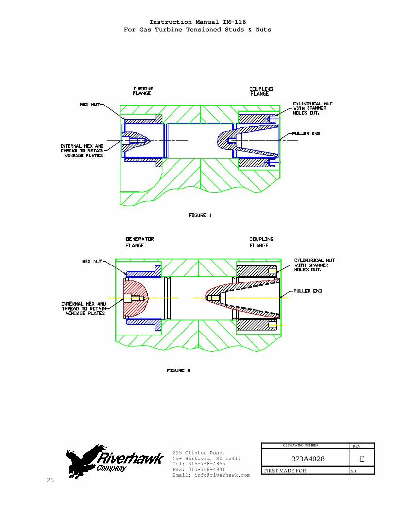
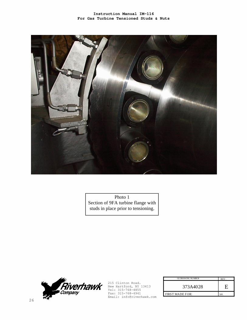
marker. Measure each stud to nearest 0.001 inch. Record each measurement on the supplied charts. Do not allow the measuring instruments to set in the sun. 6.0 Stud and Nut Assembly Refer to hardware assembly drawing (HF-0813) listed in Section 2.0 of this manual. Assemble cylindrical nut to the tapered thread end (Pull End) of the stud. Slide the stud and cylindrical nut assembly into the flange as shown in Figures 1 & 2 and install the other nut on the backside. Adjust the nut/stud assembly so that the stud protrudes from the face of the cylindrical nut the amount as depicted on the hardware drawing (HF-0813). SETTING THIS PROTRUSION OF STUD TO NUT IS CRITICAL FOR PROPER TENSIONER OPERATION. Hand tighten the assembly to a snug fit. See photos 1 & 2 for view of studs in flange prior to tensioning.
Instruction Manual IM-116 For Gas Turbine Tensioned Studs & Nuts
12
215 Clinton Road. New Hartford, NY 13413 Tel: 315-768-4855 Fax: 315-768-4941 Email: [email protected]
373A4028 E REV .
SH .FIRST MADE FOR:
GE DRAWING NUMBER
7.0 Assembly of Hydraulic Tensioner Equipment 7.1 Kit Assembly Assemble the hydraulic pump with its hose to the puller tool and bleed the system of air per following instructions. Photo 4 shows hose connected to manifold of tensioner. Clean puller screw and check for any debris and dents. Puller screw should be free to rotate and move back and forth. Seam between cylinders closed tightly. Inspect tensioner guard for any signs of damage. Bent guards should be replaced. Also, be sure the rubber pad is in place on the end of the guard, if missing, replace. 7.1.1 Fittings Make sure both male and female parts are clean and free of debris, see Figure 3 for fitting configuration. Hold female part securely when tightening so as to prevent damage to adjacent tubing. If fitting leaks first try retightening as needed. If leaking continues then disassemble and check for scratches or debris on the seating conical surfaces. Clean as required. Replace plastic caps when finished with tooling. 7.2 Pump The pump kit is shipped full of hydraulic oil. The pump reservoir cap is sealed for shipment. To use turn cap to the vent position. To prevent oil spillage close cap when not in use, during storage and shipment. Lost oil should be replaced with Enerpac Hydraulic Oil. ISO 32. Mineral Oil may be substituted, if necessary.

Instruction Manual IM-116 For Gas Turbine Tensioned Studs & Nuts
13
215 Clinton Road. New Hartford, NY 13413 Tel: 315-768-4855 Fax: 315-768-4941 Email: [email protected]
373A4028 E REV .
SH .FIRST MADE FOR:
GE DRAWING NUMBER
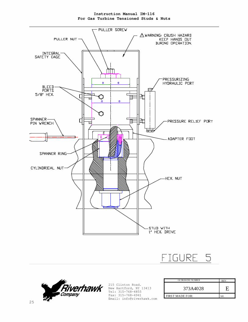
7.3 Bleeding Hydraulic System Follow the tensioner assembly instructions of Section 8.0. TO AVOID FAILURE, ENSURE SAFETY AND PROPER OPERATION THE TENSIONER ASSEMBLY MUST BE MOUNTED ON THE STUD BEFORE BLEEDING THE SYSTEM AND TENSIONING BEGINS. The tensioner has four ports see Fig. 5, one for pressurizing, two for bleeding the system and a fourth pressure relief port. To facilitate bleeding, start by first mounting the tensioner at either the 3 0’clock or 9 o’clock stud position depending on which will critically place the bleed ports in their uppermost position. In addition, make sure that the pump is always situated below the tensioner assembly. The puller tool is equipped with 5/8 in. [16 mm] Hex coned stem bleeder fittings installed in the bleeder ports. With theses two fittings loosened simultaneously, stroke the pump repeatedly until the streams of oil exiting the tool from each port are free of air, then retighten the fittings. Providing that the hose is not disconnected or loosened in the process of tensioning all the studs, bleeding the assembly once at the first position should suffice to fill the assembly and preclude the need to repeat the bleeding process. Note: The hose is stiff, use of this tooling can be simplified by temporarily mounting the puller tool on one stud prior to final tightening of fittings. This will reduce the tendency for the fittings to loosen. 8.0 Assembly of Tensioner on Stud All tensioning will be performed from the tapered thread end of the stud with orientation of the stud to the flange as shown in Figures 1 & 2. Refer to Tensioner assembly drawing and Figure 5 for tensioner to flange mounting.

Instruction Manual IM-116 For Gas Turbine Tensioned Studs & Nuts
14
215 Clinton Road. New Hartford, NY 13413 Tel: 315-768-4855 Fax: 315-768-4941 Email: [email protected]
373A4028 E REV .
SH .FIRST MADE FOR:
GE DRAWING NUMBER
This assembly has the following features which should make stud tensioning safe and easy. The safety cage is integral (bolted) to the puller tool The hydraulic piston is spring loaded to retract. The puller screw is a 2-piece design which requires that the
operator tighten the puller screw into the stud. Assembly sequence is as follows: 1. Open the hydraulic return valve on the hand pump to allow
hydraulic fluid to be pushed back from the puller tool into the pump reservoir. (This is automatic with the air-operated hydraulic pump)
2. Place the spanner ring on the puller side cylindrical nut 3. Apply a light coat of clean turbine oil or a spray lubricant
to the puller screw. Do not use “Never Seize” on the conical threads.
4. Place and hold the tensioner assembly over the end of the stud to be tightened. See photos 3,4 &5.
5. Slide the puller screw in to the tapered thread of the stud and hand tighten. Be sure not to cross thread assembly.
6. Tighten the puller screw using Allen wrenches on the puller screw and the stud. DO NOT wrench on the nut opposite the puller tool.
7. At this point the Tensioner Assembly MUST BE FREE TO ROTATE, the puller screw must be tight in the stud and the puller nut has been backed-off 2 flats.
If the puller tool is not free to rotate when the puller screw is tight, then either. (1) The tensioner is damaged, or. (2) The stud is not properly positioned in the flange and the nuts must repositioned. This can be done as follows. 1. Slightly loosen the puller screw 2. Back the nut opposite the puller tool off about 1/2 turn 3. Tighten the puller screw side nut to take up the slack. 4. Retighten the puller screw per above and check for looseness
of tool
CAUTION Personal injury and equipment damage can occur if the puller screw is not securely engaged with the tapered thread of the stud. Proper engagement is achieved when the puller screw is tight in the stud and the Tensioner Assembly is free to rotate.

Instruction Manual IM-116 For Gas Turbine Tensioned Studs & Nuts
15
215 Clinton Road. New Hartford, NY 13413 Tel: 315-768-4855 Fax: 315-768-4941 Email: [email protected]
373A4028 E REV .
SH .FIRST MADE FOR:
GE DRAWING NUMBER
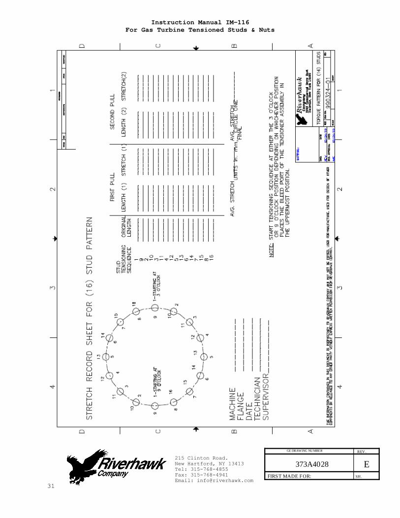
9.0 Stud Pulling and Tensioning The studs will be tensioned in two steps, at approximately 50% pressure and at final pressure. Follow the tensioning sequence for each flange joint as defined on the data sheets found at the end of this manual Note: Before threading the puller screw into the stud, carefully check the cleanliness of both the stud's and the puller screw's conical threads. Apply a light coat of clean turbine oil or a spray lubricant to the puller screw. Do not use “Never Seize” on the conical threads. This procedure will ease assembly and assure positive mating of the threads before tightening.
WARNING The safety cage MUST be in place and hands kept out of designated areas at all times when the puller tool is pressurized otherwise personal injury can occur. 9.1 Tensioning at 50% pressure After the tensioner is properly installed apply hydraulic pressure to the tool. Bring the pressure to the 50% level in accordance with the following table.
Flange Position Stud Size 50% Pressure 50% Stretch
Turbine to Coupling
2.784" [71 mm]
9000 psi [620 bar]
Do not measure Do not use
Coupling to Generator
2.283" [58 mm]
10000 psi [690 bar]
Do not measure Do not use
9.1.1 Tightening the Turbine/Coupling and Coupling/Generator Nuts Turn the cylindrical nut using the spanner ring and pin wrench as depicted in Figure 5 until it bottoms on the flange.

Instruction Manual IM-116 For Gas Turbine Tensioned Studs & Nuts
16
215 Clinton Road. New Hartford, NY 13413 Tel: 315-768-4855 Fax: 315-768-4941 Email: [email protected]
373A4028 E REV .
SH .FIRST MADE FOR:
GE DRAWING NUMBER
9.2 Removing the Tensioner from an Installed Stud Puller tool removal is to accomplished as follows:
1. Release the puller tool pressure by opening the valve on the pump. Leave the valve open. This is automatic on the air-operated hydraulic pump.
2. Unscrew the puller screw using a wrench 3. Tapping the wrench with a hammer may be necessary to loosen
the puller screw. 4. Move the tool to the next stud/nut assembly to be tensioned,
following the sequence/pattern as defined on the supplied data sheets.
9.3 Tensioning at Final Pressure Repeat the pulling and tightening procedure stated above at full pressure. Measures the length of the studs after all have been tensioned. The final pressure and required stretch values are listed in the following table
Flange Position Stud Size Final Pressure Final Stretch
Turbine to Coupling
2.784" [71 mm]
18000 psi [1170 bar]
0.011" - 0.014" [0.28 mm - 0.36 mm]
Coupling to Generator
2.283" [58 mm]
20500 psi [1240 bar]
0.019" - 0.023" [0.48 mm - 0.58 mm]
CAUTION
DO NOT EXCEED THE MAXIMUM PRESSURE VIBROSCRIBED ON THE PULLER BODY. Excessive pressure can damage the stud and the puller screw 10.0 Retensioning For the procedures of Section 9.3 excessive stretch variation or low stretch values can be corrected by retensioning all or selected studs to the pressure values stated in the above table. Have final stretch values approved by the supervisor responsible for the installation.

Instruction Manual IM-116 For Gas Turbine Tensioned Studs & Nuts
17
215 Clinton Road. New Hartford, NY 13413 Tel: 315-768-4855 Fax: 315-768-4941 Email: [email protected]
373A4028 E REV .
SH .FIRST MADE FOR:
GE DRAWING NUMBER
11.0 Thread Locking Once pulling and tensioning is complete all studs and nuts must be locked in position. The lock nuts used in the turbine/coupling and coupling/generator connections employ a mechanical locking feature. These mechanical lock nuts have two set screws located on the top face, see Figure 4. Before threading the nut onto the stud check to be certain that the set screws are free to turn. Once the nut is seated torque the set screws to the values specified in the following table. When seated and torqued to the values specified the load created by the set screw displaces the thread of the nut in the area of the web creating the desired locking action.
Stud Size Set Screw Size Torque
2.784" [71 mm] 3/8"-24 UN 200 in·lbs - 250 in·lbs
[22.6N·m – 28.2 N·m]
2.283" [58 mm] 1/4"-28 UN 80 in·lbs - 90 in·lbs
[9.0 N·m – 10.2 N·m]

Instruction Manual IM-116 For Gas Turbine Tensioned Studs & Nuts
18
215 Clinton Road. New Hartford, NY 13413 Tel: 315-768-4855 Fax: 315-768-4941 Email: [email protected]
373A4028 E REV .
SH .FIRST MADE FOR:
GE DRAWING NUMBER
12.0 Stud/Nut removal Removal is accomplished as follows:
1. Using a wire brush and shop air clean the internal tapered thread of the stud to remove any debris/deposits which may have accumulated during service. (see section 5.2.1)
2. With an Allen-wrench loosen the two locking set screws but do not remove from the nut see Figure 4.
3. Install the appropriate puller tool to the stud as described in Section 8.0.
4. Apply the appropriate hydraulic pressure per the following Table and using the spanner ring and spanner/pin wrenches shown in Figure 5 loosen the nut, then release the pressure and remove the puller tool.
Flange Position Stud Size Removal Pressure
Turbine to Coupling 2.784" [71 mm]
18000 psi [1170 bar]
Coupling to Generator 2.283" [58 mm]
20500 psi [1240 bar]
Instruction Manual IM-116 For Gas Turbine Tensioned Studs & Nuts
19
215 Clinton Road. New Hartford, NY 13413 Tel: 315-768-4855 Fax: 315-768-4941 Email: [email protected]
373A4028 E REV .
SH .FIRST MADE FOR:
GE DRAWING NUMBER
13.0 frequently Asked Questions This section contains some frequently asked questions and problems. If the steps listed here do not solve your problem, contact the Riverhawk Company thru our website, email, or phone call. Q: A tensioner has pulled itself out of the stud's conical threads. Can I continue using a tensioner on this stud? A: No. Both the tensioner and the stud may have been damaged. If the stud is tensioned, a Nut Buster repair kit, from Riverhawk, must be used to remove the damaged stud by drilling out the nut. Riverhawk can supply a replacement stud and nut based on the initial weight certification supplied with the hardware set (see section 4.2). The damaged tensioner should also be returned to Riverhawk for inspection and repair. Q: The hydraulic tensioner has been taken up to its final pressure. The final stretch length is short of the final stretch target. What is the next step? A: Do not increase the hydraulic pressure. Check if the hydraulic pump is set to the right pressure. Install the tensioner and re-pressurize the tensioner to the final pressure then recheck the stretch measurement. If the stretch value is still short, remove the stud from the hole and re-measure the stud's initial length then try to install the stud again. Q: The hydraulic tensioner has been taken up to its final pressure. The final stretch length is larger than the final stretch target. What is the next step? A: Remove the stud from the bolt hole. Check if the hydraulic pump is set to the right pressure. Re-measure the stud's initial length then try to install the stud again.

Instruction Manual IM-116 For Gas Turbine Tensioned Studs & Nuts
20
215 Clinton Road. New Hartford, NY 13413 Tel: 315-768-4855 Fax: 315-768-4941 Email: [email protected]
373A4028 E REV .
SH .FIRST MADE FOR:
GE DRAWING NUMBER
Q: Is there an easier way to support or move the tensioner around the coupling shaft? A: Use two straps. One around the coupling shaft and the other
attach to any overhead support. Straps must be slack during mounting tensioner to stud and during tensioning.
Q: The tensioner is at its final pressure, but the nut cannot be loosen. A: If the nuts cannot be loosened at the final pressure, continually increasing the pressure will not help and can be dangerous and in some cases make it harder to remove the nut. Check the nut to see if its set screws have been loosened. Check for and remove any corrosion around the nut's threads. Q: How do I clean the conical threads on a stud? A: The conical threads are best cleaned using a spiral wound brass brush in a drill as described in section 5.2.1 Q: During the initial steps of removing a tensioned stud, the stick-out length is found to be wrong. A: Do not proceed. Contact Riverhawk for assistance. With the wrong stick-out length, the hydraulic tensioner has a limited stroke and may not work properly and can be damaged. Q: The hydraulic pump appears to be leaking. A: Check the hose connection to the hydraulic pump. If the 1/4"
high pressure fitting is not assembled correctly, it may look like the pump is leaking. If the problem continues, it may be necessary to open the pump kit. Contact Riverhawk for guidance.
Instruction Manual IM-116 For Gas Turbine Tensioned Studs & Nuts
21
215 Clinton Road. New Hartford, NY 13413 Tel: 315-768-4855 Fax: 315-768-4941 Email: [email protected]
373A4028 E REV .
SH .FIRST MADE FOR:
GE DRAWING NUMBER
Q: The hydraulic hose has a collar on it that can't be moved by hand A: The collar is sometimes held in place with a thread locking
compound. This prevents the collar from moving too easily. It may be necessary to adjust this collar with a set of vise-grip pliers. Be careful to not strip the threads off the tube or hose end.

Instruction Manual IM-116 For Gas Turbine Tensioned Studs & Nuts
22
215 Clinton Road. New Hartford, NY 13413 Tel: 315-768-4855 Fax: 315-768-4941 Email: [email protected]
373A4028 E REV .
SH .FIRST MADE FOR:
GE DRAWING NUMBER
14.0 Revision History
Revision Letter
Effective Date
Description
E Jun 10, 2009 Added turbine oil and removed “Never Seize” from sections 1.0, 3.0, 8.0, and 9.0
D Mar 25, 2009 Added sections 3 and 13, Added GE Title block to all pages
C Jun 23, 2000 Page 2 para 2.0, Page 4 para 4.0, Page 5 para 5.3, page 7 para 7.3
B Jan 11, 2000 Page 1
A Jul 20, 1999
- Mar 19, 1999 Released
Instruction Manual IM-116 For Gas Turbine Tensioned Studs & Nuts
23
215 Clinton Road. New Hartford, NY 13413 Tel: 315-768-4855 Fax: 315-768-4941 Email: [email protected]
373A4028 E REV .
SH .FIRST MADE FOR:
GE DRAWING NUMBER

Instruction Manual IM-116 For Gas Turbine Tensioned Studs & Nuts
24
215 Clinton Road. New Hartford, NY 13413 Tel: 315-768-4855 Fax: 315-768-4941 Email: [email protected]
373A4028 E REV .
SH .FIRST MADE FOR:
GE DRAWING NUMBER
Instruction Manual IM-116 For Gas Turbine Tensioned Studs & Nuts
25
215 Clinton Road. New Hartford, NY 13413 Tel: 315-768-4855 Fax: 315-768-4941 Email: [email protected]
373A4028 E REV .
SH .FIRST MADE FOR:
GE DRAWING NUMBER
Instruction Manual IM-116 For Gas Turbine Tensioned Studs & Nuts
26
215 Clinton Road. New Hartford, NY 13413 Tel: 315-768-4855 Fax: 315-768-4941 Email: [email protected]
373A4028 E REV .
SH .FIRST MADE FOR:
GE DRAWING NUMBER
Photo 1 Section of 9FA turbine flange with studs in place prior to tensioning.

Instruction Manual IM-116 For Gas Turbine Tensioned Studs & Nuts
27
215 Clinton Road. New Hartford, NY 13413 Tel: 315-768-4855 Fax: 315-768-4941 Email: [email protected]
373A4028 E REV .
SH .FIRST MADE FOR:
GE DRAWING NUMBER
Photo 2 Back side of 9FA turbine flange showing studs and nuts in place.

Instruction Manual IM-116 For Gas Turbine Tensioned Studs & Nuts
28
215 Clinton Road. New Hartford, NY 13413 Tel: 315-768-4855 Fax: 315-768-4941 Email: [email protected]
373A4028 E REV .
SH .FIRST MADE FOR:
GE DRAWING NUMBER
Photo 3 Side view of tensioner mounted
on 9FA turbine flange.

Instruction Manual IM-116 For Gas Turbine Tensioned Studs & Nuts
29
215 Clinton Road. New Hartford, NY 13413 Tel: 315-768-4855 Fax: 315-768-4941 Email: [email protected]
373A4028 E REV .
SH .FIRST MADE FOR:
GE DRAWING NUMBER
Photo 4 Tensioner in operation while
mounted on 9FA turbine flange.

Instruction Manual IM-116 For Gas Turbine Tensioned Studs & Nuts
30
215 Clinton Road. New Hartford, NY 13413 Tel: 315-768-4855 Fax: 315-768-4941 Email: [email protected]
373A4028 E REV .
SH .FIRST MADE FOR:
GE DRAWING NUMBER
Photo 5 View of operator tightening nuts
on Fr. 9FA turbine flange
Instruction Manual IM-116 For Gas Turbine Tensioned Studs & Nuts
31
215 Clinton Road. New Hartford, NY 13413 Tel: 315-768-4855 Fax: 315-768-4941 Email: [email protected]
373A4028 E REV .
SH .FIRST MADE FOR:
GE DRAWING NUMBER