illumination models for graphics
TRANSCRIPT

Illumination Illumination Models for Models for GraphicsGraphics
CS 211ACS 211A
Can be very complexCan be very complex• The incoming light can come from a
source, or bouncing off another object, or after multiple bounces
• Sources can be extended• Multiple interactions between light
and surface
Very simple modelsVery simple models• Assumes point light source• Models only the direct illumination
from the source–Does not consider light reaching after
bouncing off other objects
• Illumination models evaluated only at the vertices
For every vertexFor every vertex• Ambient component• Diffused component• Specular component

Ambient ComponentAmbient Component• Equal amount of light from all
directions• Approximates the indirect
illumination• Iaka
– Ia = intensity of ambient light–ka= percentage of the light reflected by
the object
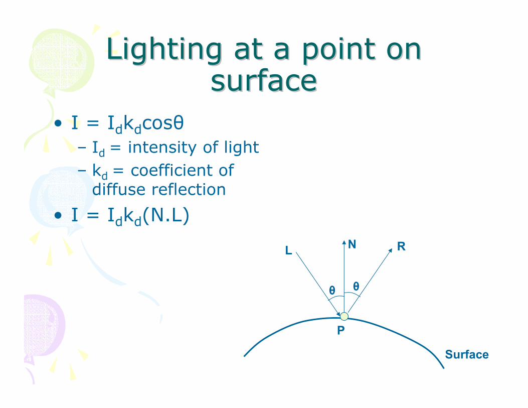
Lighting at a point on Lighting at a point on surface surface
• I = Idkdcosθ– Id = intensity of light– kd = coefficient of
diffuse reflection
• I = Idkd(N.L)
Surface
NL
θ θ
R
P
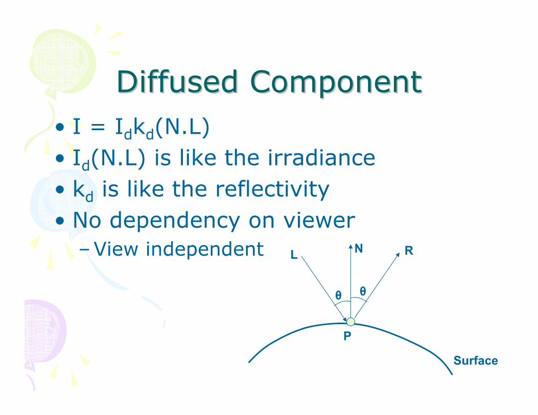
Diffused Component Diffused Component • I = Idkd(N.L)• Id(N.L) is like the irradiance• kd is like the reflectivity• No dependency on viewer
–View independent
Surface
NL
θ θ
R
P

Ambient and Diffused Ambient and Diffused LightingLighting
I = Ipkd(N.L)
I = (Iaka +Ipkd(N.L))

SpecularSpecular ComponentComponent• IsksCosn(α)• Cos(α): fall off as V
moves away from R
• n gives the sharpness
L
θ θV
R
α
P

SpecularSpecular ComponentComponent• R depends on L • Depends on both V
and L• Like the BRDF• n controls the
view-dependency also
L
θ θV
R
α
P

Providing ControlProviding Control• Providing enough control so that one
can simulate effect via trial and error of many different parameters
• May be not be close to the physical phenomenon
• For e.g. Different brightness of the same light can be used for different component computation

Attenuation ControlAttenuation Control• Diffused component
• I = Idfattkd(N.L)– fatt = 1/(a+bd+cd2)
• d = distance of light from the surface• a, b and c are user defined constants
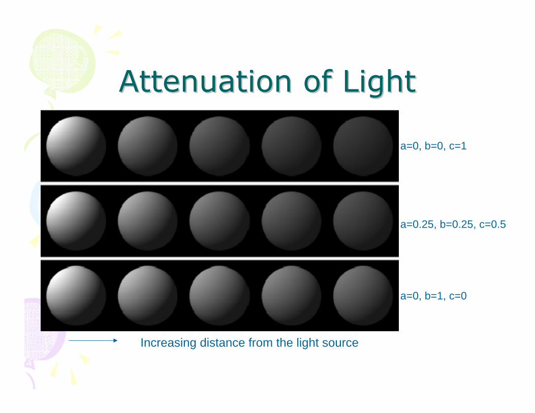
Attenuation of LightAttenuation of Light
Increasing distance from the light source
a=0, b=0, c=1
a=0.25, b=0.25, c=0.5
a=0, b=1, c=0

Other issuesOther issues• (Iaka + Idkd(N.L) + IsksCosn(α))O• For different channels
–Do the same operation for all channels
• Multiple lights–Only one ambient light source–Multiple point light sources
• Addition of light from different lightsources

Ambient Ambient

Ambient + DiffuseAmbient + Diffuse

Ambient + Diffuse + Ambient + Diffuse + SpecularSpecular

What is Shading?What is Shading?• Illumination model• How do we use
these models to shade the triangles in the graphics pipeline?
• How did we generate the picture on the right?

MethodMethod• Evaluate illumination model at the
vertices of the triangles–After model-view transformation
• Use interpolation to color the interior of the triangles during rasterization–Different shading methods use different
interpolation• Assume that the polygonal models
approximate smooth surfaces

Normal ComputationNormal Computation
• Normal of a triangle– N = (B-A) x (C-A)
• Vertices are in anticlockwise direction with respect to normal
• Normal of a vertex–Average of all the
triangle incident on the vertex
–Nv = (N1+N2+N3+N4)/4
A
B
C
N

Constant/Flat/Faceted ShadingConstant/Flat/Faceted Shading
• Illumination model applied once per triangle
• Using normal of the triangle• Shade the whole triangle uniformly
–Color associated with triangles and not vertices

GouraudGouraud ShadingShading• Interpolating illumination between
vertices– Calculate the illumination using vertex
normals at vertices– Bilinear interpolation across the triangle
GouraudGouraud ShadingShading
• Edges get same color, irrespective of which triangle they are rendered from– Shading is continuous at edges
• Tends to spread sharp illumination spots over the triangle

PhongPhong ShadingShading• Interpolate the normal across the
triangle• Calculate the illumination at every
pixel during rasterization–Using the interpolated normal
• Slower than Gouraud• Does not miss specular highlights
–Good for shiny specular objects

GouraudGouraud vs. vs. PhongPhong ShadingShading
Spreads highlights across the triangle
Misses a highlight completely
Gouraud Phong
Gouraud Phong

Flat ShadingFlat Shading

GouraudGouraud ShadingShading

PhongPhong ShadingShading

ShadingShading• Independent of the Illumination
model used• Phong Shading and Phong
Illumination• Artifacts
–Piecewise planar approximation–Screen Space Interpolation
• Simple and hence widely used

Artifacts: Mach BandsArtifacts: Mach Bands
Actual Intensity
Percieved Intensity
At discontinuities

Artifacts: Mach BandsArtifacts: Mach Bands• Common in flat shading since
shading is discontinuous at edges• Also present in Gouraud shading
–Gradient of the shading may change suddenly
• Phong shading reduces it significantly–But cannot be eliminated–At sharp changes in surface gradient
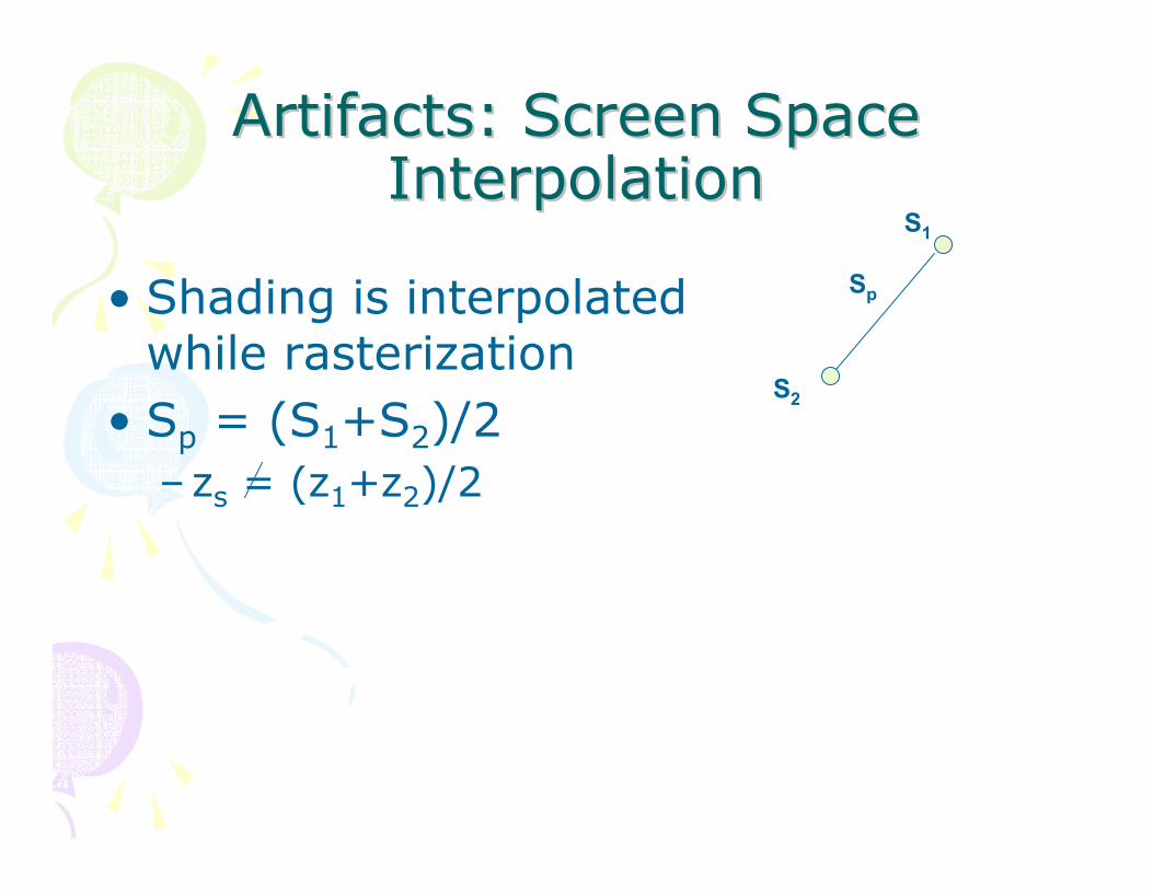
Artifacts: Screen Space Artifacts: Screen Space InterpolationInterpolation
• Shading is interpolated while rasterization
• Sp = (S1+S2)/2–zs = (z1+z2)/2
S1
S2
Sp

Artifacts: TArtifacts: T--junctionsjunctions• The shading at the T-junction are
different when calculated from different triangles
• Shading discontinuity
A
B
C
D

Artifacts:VertexArtifacts:Vertex NormalsNormals• Vertex normal does not reflect the
curvature of the surface adequately–Appear less flat than it actually is