ilerda-40 ssb transceiver kitiler-40 mk2 ssb qrp transceiver kit page 4 acknowledgments to andy,...
TRANSCRIPT

ILER-40 MK2 SSB QRP Transceiver Kit Page 1
ILER-40 MK2 QRP SSB Transceiver Kit
Assembly manual Last update: July 20, 2015
Translated by Marlin, KC0O
Most recent updates and news at: www.qsl.net/ea3gcy
Thanks for constructing the ILER-20 MK2 SSB Transceiver kit
Have fun assembling it and enjoy QRP! 73 Javier Solans, ea3gcy

ILER-40 MK2 SSB QRP Transceiver Kit Page 2
INDEX
INDEX ................................................................................................................................... 2
INTRODUCTION ................................................................................................................... 3
SPECIFICATIONS ................................................................................................................ 4
TIPS FOR FIRST TIME BUILDERS ..................................................................................... 5
PARTS LIST SORTED BY VALUE/QUANTITY .................................................................. 7
INDIVIDUAL PARTS LIST.................................................................................................... 9
120-QUADRANT COMPONENT LAYOUT MAP ................................................................. 13
ASSEMBLY ......................................................................................................................... 14
ADJUSTMENT AND TESTING ........................................................................................... 27
IF YOUR KIT DOES NOT WORK AFTER FINISHING ASSEMBLY .................................. 32
LIMITED WARRANTY ......................................................................................................... 34
SCHEMATIC ........................................................................................................................ 35
WIRING ................................................................................................................................ 36

ILER-40 MK2 SSB QRP Transceiver Kit Page 3
INTRODUCTION
What is the significance of ILER? A
little bit history…
The origin of LLEIDA goes back to 5th
century B.C. when the Iberian people of
the ILERGETAS settled on top of the
"Cerro de la Seu Vella" (Hill of the Old
See) and founded the city of ILTIRDA.
Their most well-known leaders were
Indibil and Mandonio, who defended
against the Carthaginians and Romans,
but were defeated in the year 205 B.C.,
and thereafter the city was Romanized
and renamed ILERDA.
LLEIDA is the current name of this city
in the northeast of Spain.
Photo: Seu Vella de Lleida.
ILER-40 MK2
The circuit of the ILER kits is a Spanish redesign of the 80 meter transceiver “Antek” by Andy SP5AHT,
published in the magazine “Swiat Radio.” By switching the LO and the BFO between the two NE602's,
each one carries out two different functions determined by TX or RX mode. One NE602 functions as a
receive mixer and a DSB generator, and the other NE602 functions as a transmit mixer and a SSB
demodulator.
A quartz crystal controlled local oscillator (LO) tunes a segment with a range of 25-100 KHz.
The optional “ILER-DDS” kit makes it possible to cover the entire band.
The transmitter has a robust design to withstand and work hard in the field!
The philosophy of this transceiver is:
"Put in just the minimum that it needs to work, and work well!"
There are only two controls: volume and tuning, which are sufficient for enjoying the pleasure of QRP!

ILER-40 MK2 SSB QRP Transceiver Kit Page 4
Acknowledgments
To Andy, SP5AHT, for his important contribution to the world of amateur radio.
To Jon Iza, EA3SN, for his educational articles and contribution to technical data.
To Luis EA3WX, Juan EA3FXF, Jaime EA3HFO, Alfonso EA3BFL and to J. Antonio Beltrán for the help
they gave in making this kit a reality, from the first prototype to the current ILER-17.
To “eaqrpclub.com” for keeping the "tinkering" flame burning even during difficult times.
SPECIFICATIONS
GENERAL:
Frequency coverage: VXO that tunes a 30 to 100 KHz segment of the 40M band (recommended 50-
60KHz max. to obtain reasonable stability). The range of coverage is selected by means of the value of
L6 in the VXO circuit.
Frequency control: Quartz crystal controlled oscillator (VXO).
Option A: a pair of 12.031MHz crystals. (upper limit approx. 7.105MHz)
Option B: one 12.096MHz crystal. (upper limit approx. 7.185MHz)
Variable tuning capacitor (polyvaricon).
Antenna: 50 ohms.
Power supply: 12-14VDC, 35mA in receive (without signal), 1000-1100mA in transmit.
Components: 65 resistors, 83 capacitors, 3 variable resistors, 1 trimmer capacitor, 1 potentiometer
(volume), 8 IC's, 14 transistors, 12 inductors-chokes, 6 RF transformers, 1 variable tuning capacitor, 6
crystals.
Front panel controls: tuning, volume.
Optional controls: RX attenuator potentiometer, RX attenuator switch.
External connections: mic/ptt, speaker jack, antenna, DC input.
Circuit board dimensions: 100x120 mm.
TRANSMITTER:
RF output: 4-5 W (12-14V)
Second harmonic output: -42dB below the fundamental frequency.
Other spurious signals: all signals -50dB or better below the fundamental frequency.
Carrier suppression: better than -45dB.
T/R switching: Relays.
Microphone preamp with bandpass.
Microphone: dynamic, approx. 600 ohms, CB type or similar (not included).
RECEIVER:
Type: Superheterodyne, balanced mixer.
Sensitivity: 0.250uV minimum discernible signal.
Selectivity: 4-pole crystal ladder filter, 2.2 KHz nominal bandwidth.
IF Frequency: 4.915 MHz.
Built-in audio preamp and AGC.
Audio output: 250mW @ 8 Ohms.

ILER-40 MK2 SSB QRP Transceiver Kit Page 5
PLEASE READ ALL OF THE ASSEMBLY
INSTRUCTIONS COMPLETELY AT LEAST ONCE
BEFORE BEGINNING.
TIPS FOR FIRST TIME BUILDERS
Tools required:
- A 15-30w soldering iron with fine tip, small wire cutters for cutting component leads, wire strippers,
long-nose pliers, needle-nose pliers, X-Acto knife, screwdriver for M3 screws, alignment tool for
adjusting IF transformers.
- You will need a good light and a magnifying glass to see the fine print on the components and other
assembly details.
Instruments required:
- Multimeter, oscilloscope (desirable but not essential), frequency counter or HF receiver, RF power
meter, dummy load: 5W - 50 Ohms, RF generator (desirable but not essential).
Soldering:
There are two important things which need to be done to insure successful operation of a kit. The first is
to put the component into the proper place on the circuit board; the second is good soldering.
To solder properly, you must use a high-quality solder for electronics use and the correct type of iron.
Use a small soldering iron with a fine, pointed tip. The soldering iron should be about 15-30 watts (if it is
not thermostatically controlled). Use only high-quality electronic type solder. NEVER use any extra flux.
You should hold the hot soldering iron in contact with both the circuit board and the component lead for
about two seconds to heat them up. Then, keeping the soldering iron in place, touch the solder at the
junction of the lead and trace and wait about two seconds or so until the solder flows between the
terminal and the trace to form a good joint. Now remove the soldering iron. The soldering iron should
have been in contact with the work piece for a total time of about 4 seconds. After soldering each joint,
you should clean the soldering tip, removing any excess solder. This prevents mixing in old solder and
residues from previous soldering operations.

ILER-40 MK2 SSB QRP Transceiver Kit Page 6
Finding the correct component:
IC's
The component outline for the IC printed on the circuit board has a “U” shaped notch on one end,
indicating the end at which pin 1 of the IC is located. There is a similar notch on one end of the IC socket
that should be oriented over the “U” printed on the circuit board. Finally, pin 1 of the IC is also marked
with a small dimple or dot; this end of the IC should be oriented towards the notch in the IC socket or the
"U" of the component outline.
Diodes
Be careful to observe the correct polarity of the diodes. There is a black band towards one end of the
diode. This band should be oriented towards the line printed on the component outline of the circuit
board.
Electrolytic capacitors:
These must be placed with the correct polarity. The positive lead (+) is always the long lead. The
negative terminal (-) is the short lead and is marked by a stripe on the body of the capacitor. Make sure
that the positive lead of the capacitor goes through the hole marked with a "+" on the circuit board.
Coils and transformers:
You may find it convenient to wind and prepare all the coils and transformers before beginning to mount
the components. That way you won't have to stop and possibly lose concentration while winding them.
This is the part of the construction that some consider to be the most difficult. I personally find it to be
one of the easiest stages, and it can even be relaxing. Look for the most appropriate moment to do it,
and most importantly, take your time. The drawings and instructions in the manual will illustrate and
accompany you in the process.

ILER-40 MK2 SSB QRP Transceiver Kit Page 7
PARTS LIST SORTED BY VALUE/QUANTITY
Resistor list Qty Value Checked Ref. Identified
5 1 R33, R51, R57, R60, R61 brown-black-gold
1 10 R1 brown-black-black
2 22 R15, R56 red-red-black
4 100 R13, R39, R50, R52 brown-black-brown
1 270 R58 red-violet-brown
2 470 R46, R54 yellow-violet-brown
13 1K R2, R7, R10, R16, R30, R38, R42, R47, R53, R59, R62, R63, R64 brown-black-red
1 1K2 R45 brown-red-red
1 1K5 R32 brown-green-red
4 4K7 R4, R25, R48, R55 yellow-violet-red
9 10K R3, R5, R11, R12, R14, R22, R31, R34, R35 brown-black-orange
7 22K R27, R36, R37, R40, R41, R43, R44 red-red-orange
1 33K R26 orange-orange-orange
3 47K R21, R28, R29 yellow-violet-orange
2 56K R8, R9 green-blue-orange
1 150K R18 brown-green-yellow
1 180K R6 Brown-gray-yellow
1 220K R20 red-red-yellow
1 270K R24 red-violet-yellow
2 470K R17, R19 yellow-violet-yellow
1 1M R23 brown-black-green
1 1K P1 RX-gain pot. w/shaft (optional no included) 1K lin.
1 10K P4 Volume control pot. w/shaft 10K
2 5K P2, P3 ajustable trimmer 502 or 53E
1 500 P5 ajustable trimmer 501 or 52Y
Capacitor list Qty Value Checked Ref. Identified
35 100n C1, C2, C3, C9, C12, C14, C15, C22, C23, C24, C28, C29, C31, C32 104 or 0.1 C33, C39, C43,C44, C48, C50, C51, C56, C59, C60, C64, C65, C67, C70, C71, C72, C73, C75, C77, C78, C82
5 10n C26, C40, C68, C69, C76 103 or 0.01
5 1n C34, C47, C55, C57, C66 102 or 0.001
1 1n C80 Polystyrene 1000
2 470p C79, C81 Polystyrene 470
1 330p C10 n33 or 331
4 220p C16, C27, C45, C46 n22 or 221
2 100p C52, C53 101
4 82p C4, C6, C61, C63 82P
1 47p C54 47P
5 33p C17, C18, C19, C20, C21 33P or 33J
1 27p C7 27P or 27J
1 12p C83 12P or 12J
2 8p2 C5, C62 8P2
1 220uf C36 (elec.) 220uf 25v or 35V
5 100uf C25, C30, C35, C41, C42 (elec.) 100uf 25V or 35V
6 10uf C8, C11, C37, C38, C49, C74, (elec.) 10uf 25V or 35V
1 1uf C13 (elec.) 1uf 25V, 35V or 63V
1 60p CV1 Murata trimer BFO Brown
1 160p CV2+CV3 Polyvaricon dual gang. Tuning. 160p + 70p 70p

ILER-40 MK2 SSB QRP Transceiver Kit Page 8
Semiconductors list Qty Type Checked Ref. Identified
Transistors
11 BC547 Q1, Q2, Q3, Q4, Q5, Q6, Q7, Q8, Q9, Q10, Q11 BC547
1 2N2222 Q12 2N2222
1 2N5109 Q13 2N5109
1 2SC1969/2078 Q14, washer and mica spacer C1969 or C2078
Integrated circuits
1 LM741 IC1 LM741CN or UA741
2 SA/NE602 IC2, IC3 SA602AN or NE602AN
1 LM386 IC4 LM386N-1
1 78L05 IC8 MC78L05
1 78L06 IC5 MC78L06
2 78L08 IC6, IC7 MC78L08
Diodes
5 1N4148 D1, D2, D3, D4, D5 4148
2 1N4001(7) D6, D7 1N4001 or 1N4007
1 47V D8, Zener 47V 1W BZX85C47
1 LED D9, bicolor Led -
Inductors/RF Transformers list/Crystals/Relays Qty Value Checked Ref. Identified
6 100uH L1, L2, L3, L5, L7, L9 Axial inductor brown, black, brown
1 39uH L4 Axial inductor orange, white, black
2 VK200 L8, L10 Choque
2 T37-2 L11, L12 LPF toroids 9.5 mm diam. Red
1 T68-2 L6 Toroid. Tuning inductor 18 mm diam. Red
4 5u3H (3334) T1, T2, T3, T4 coils 5u3H 5u3H
2 FT37-43 T6 toroid 8t+8t ; T5 toroid 10t - 3t 9.5 mm diam. Black
5 4.915 X1, X2, X3, X4, X5 Crystals 4.915MHz. 4.915
2/1 12.031/ 12.096 X6, X7 12.031MHz crystals or X7 12.096MHz X6 none 12.031 or 12.096
2 Relays RL1, RL2 -
Hardware Qty Value Checked Ref. Identified
5 nuts hex nuts M3 -
4 spacers 5mm spacer for M3 screw -
4 screw 5mm M3 screw -
1 screw 10mm M3 screw -
2 screw 4mm M2,5 screw (for Polyvaricon)
1 screw 12mm M2,5 screw (for Polyvaricon )
1 washer M3 lock washer -
29 pins Mic, 12V, ATT, P1-RXG, ANT, ALT, D7, VXO, BFO, J1, J2, K1, K2, S -
3 jumper jumpers for J1, J2 and P1RXG -
4 IC socket IC’s socket 8 pin -
1 Shaft Poly. 6mm Shaft Polyvaricon Hardware -
1 Heatsink Q14 (Output Amp) Heatsink -
1 Heatsink Q13 (Driver) Heatsink small
110cm wire 110cm enameled copper wire 0,5mm -
115cm wire 100cm enameled copper wire 0,3mm -
1 ILER MK2 PCB 100mm x 120mm ILER MK2 PCB -

ILER-40 MK2 SSB QRP Transceiver Kit Page 9
LIST OF INDIVIDUAL COMPONENTS
Resistors Checked Ref. Value Ident./Comment Circuit section Located
R1 10 brown-black-black RX att. B-10
R2 1K brown-black-red RX att. C-10
R3 10K brown-black-orange Mic. Preamp F-9
R4 4K7 yellow-violet-red Mic. Preamp E-9
R5 10K brown-black-orange Mic. Preamp F-9
R6 180K brown-gray-yellow Mic. Preamp F-8
R7 1K brown-black-red Mic. Preamp G-7
R8 56K green-blue-orange DSB gen/RX mix F-6
R9 56K green-blue-orange DSB gen/RX mix F-5
R10 1K brown-black-red Carrier ctrl. E-5
R11 10K brown-black-orange Carrier ctrl. D-6
R12 10K brown-black-orange Carrier ctrl. D-5
R13 100 brown-black-brown Mic.Preamp F-8
R14 10K brown-black-orange RX RF mute D-7/8
R15 22 red-red-black Dem/Gen supply G-3/4
R16 1K brown-black-red AGC input G-7
R17 470K yellow-violet-yellow Audio AGC-preamp H-9
R18 150K brown-green-yellow Audio AGC-preamp H-8
R19 470K yellow-violet-yellow Audio AGC-preamp G-9
R20 220K red-red-yellow Audio AGC-preamp G-8
R21 47K yellow-violet-orange Audio AGC-preamp G-9
R22 10K brown-black-orange Audio AGC-preamp H-10
R23 1M brown-black-green Audio AGC-preamp H-9
R24 270K red-violet-yellow Audio AGC-preamp H-8
R25 4K7 yellow-violet-red Audio AGC-preamp H-10
R26 33K orange-orange-orange Audio AGC-preamp H-9/10
R27 22K red-red-orange Audio AGC-preamp I-9/10
R28 47K yellow-violet-orange Audio AGC-preamp I-8
R29 47K yellow-violet-orange Audio AGC-preamp J-8
R30 1K brown-black-red Audio Amp mute J-9
R31 10K brown-black-orange Audio Amp mute L-7/8
R32 1K5 brown-green-red Audio Amp mute L-6
R33 1 brown-black-gold Audio Amp Out. K/L-9
R34 10K brown-black-orange BFO offset L-5
R35 10K brown-black-orange BFO offset L-5
R36 22K red-red-orange BFO J-7
R37 22K red-red-orange BFO J-6
R38 1K brown-black-red BFO I-6/7
R39 100 brown-black-brown BFO I-6
R40 22K red-red-orange VXO I-3
R41 22K red-red-orange VXO J-4/5
R42 1K brown-black-red VXO J-4/5
R43 22K red-red-orange VXO I-2
R44 22K red-red-orange VXO I-4
R45 1K2 brown-red-red VXO I-4
R46 470 yellow-violet-brown VXO I-4/5
R47 1K brown-black-red TX Pre-driver G-2
R48 4K7 yellow-violet-red TX Pre-driver H-2
R49 -- NO USED TX Pre-driver I-1
R50 100 brown-black-brown TX Pre-driver I-1
R51 1 brown-black-gold TX Pre-driver F-1
R52 100 brown-black-brown TX Driver E/F-3
R53 1K brown-black-red TX Driver E/F-2
R54 470 yellow-violet-brown TX Driver D-2
R55 4K7 yellow-violet-red TX Driver D-2

ILER-40 MK2 SSB QRP Transceiver Kit Page 10
R56 22 red-red-black TX Driver C-1
R57 1 brown-black-gold TX Driver B-1
R58 270 (BIAS) red-violet-brown BIAS TX Out Amp C-3/4
R59 1K brown-black-red TX Out Amp A-3
R60 1 brown-black-gold TX Out Amp B-1/2
R61 1 brown-black-gold TX Out Amp A-1/2
R62 1K brown-black-red Bi-color LED K-6
R63 1K brown-black-red Bi-color LED L-6
R64 1K brown-black-red TX Pre-driver G-2
R65 -- NO USED TX Pre-driver F-2
P1 1K RX-GAIN Pot. w/shaft optional Rx-Gain Control A-9
P2 5K 502 or 53E trimmer Mic preamp F-10
P3 5K 502 or 53E trimmer DSB gen / Rx mix F-5
P4 10K VOLUME pot. w/shaft 10K Audio Amp volume L-8/9
P5 500 501 or 52Y trimmer “Bias” out amp C-4
Capacitors
Checked Ref. Value Ident./Comment Circuit section Located
C1 100n 104 or 0.1 RX input A-8
C2 100n 104 or 0.1 RX input A-8
C3 100n 104 or 0.1 RX att C-10
C4 82p 82P BPF RX C-9
C5 8p2 8P2 BPF RX C-8
C6 82p 82P BPF RX C-9
C7 27p 27p or 27J DSB gen/RX mix E-7/8
C8 10uF 10uf 25V or 35V (elec) Mic preamp E-10
C9 100n 104 or 0.1 Mic preamp E-10
C10 330p n33 or 331 Mic preamp E-8
C11 10uF 10uf 25V or 35V (elec) Mic preamp F-9
C12 100n 104 or 0.1 Mic preamp F-8
C13 1uF 1uF 25V, 35V or 63V (elec) DSB gen/RX mix G-6/7
C14 100n 104 or 0.1 Carrier ctrl. D-5
C15 100n 104 or 0.1 DSB gen/RX mix F-6
C16 220p n22 or 221 DSB gen/RX mix H-6
C17 33p 33p or 33J FI xtal filter F-7
C18 33p 33p or 33J FI xtal filter E-6
C19 33p 33p or 33J FI xtal filter E-5
C20 33p 33p or 33J FI xtal filter E-4/5
C21 33p 33p or 33J FI xtal filter E/F-4
C22 100n 104 or 0.1 SSB dem/TX mix E-3
C23 100n 104 or 0.1 IC2-IC3 supply H-3
C24 100n 104 or 0.1 IC2-IC3 supply G-5
C25 100uF 100uF 25V or 35V (elec) C3 supply F-4
C26 10n 103 or 0.01 IC3 supply H-4
C27 220p n22 or 221 SSB dem/TX mix H-5
C28 100n 104 or 0.1 Audio AGC-preamp G-8
C29 100n 104 or 0.1 Audio AGC-preamp G-8
C30 100uF 100uF 25V or 35V (elec) Audio AGC-preamp G-9
C31 100n 104 or 0.1 Audio AGC-preamp H-9/10
C32 100n 104 or 0.1 Audio AGC-preamp I-9
C33 100n 104 or 0.1 Audio AGC-preamp I/J-9
C34 1n 102 or 0.001 Audio AGC-preamp I-8
C35 100uF 100uF 25V or 35V (elec) Audio AGC-preamp I/J-10
C36 220uF 220uF 25V or 35V (elec) VCC supply H-7
C37 10uF 10uF 25V or 35V (elec) Audio Amp out. J-10
C38 10uF 10uF 25V or 35V (elec) Audio Amp out. J-9
C39 100n 104 or 0.1 Audio Amp out. K-8
C40 10n 103 or 0.01 Audio Amp out. L-9/10
C41 100uF 100uf 25V or 35V (elec) Audio Amp mute L-7
C42 100uF 100uF 25V or 35V (elec) Audio Amp out. K-10
C43 100n 104 or 0.1 Audio Amp out. K-8
C44 100n 104 or 0.1 BFO offset L-4

ILER-40 MK2 SSB QRP Transceiver Kit Page 11
Crystals
Cheked Ref. Frequency Ident./Comment Circuit section Located
X1 4.915MHz I.F. E-7
X2 4.915MHz I.F. E-6
X3 4.915MHz I.F. E-5
X4 4.915MHz I.F. E-4
X5 4.915MHz BFO J/K-6
X6 12.031MHz or none VXO J-3
X7 12.031MHz or 12.096MHz VXO I-3
Semiconductors Cheked Ref. Type Ident./Comment Circuit section Located
Transistors
Q1 BC547 BC547 RX RF mute C-8
Q2 BC547 BC547 Carrier switch D-6
Q3 BC547 BC547 Audio AGC preamp H-9
Q4 BC547 BC547 Audio AGC preamp H-8
Q5 BC547 BC547 Audio AGC preamp I-9
C45 220p n22 or 221 BFO I-7
C46 220p n22or 221 BFO J-6
C47 1n 102 or 0.001 BFO I-7
C48 100n 104 or 0.1 BFO J-7
C49 10uF 10uF 25V or 35V (elec) BFO/VXO supply K-7
C50 100n 104 or 0.1 BFO/VXO supply I-8
C51 100n 104 or 0.1 VXO K-3/4
C52 100p n10 or 101 VXO K-4/5
C53 100p n10 or 101 VXO J-4/5
C54 47p 47p or 47J VXO J-4/5
C55 1n 102 or 0.001 VXO H-4
C56 100n 104 or 0.1 VXO K-4/5
C57 1n 102 or 0.001 TX Pre driver input G-3
C58 -- NO USED TX Pre-driver I-1/2
C59 100n 104 or 0.1 TX supply C-5
C60 100n 104 or 0.1 TX Pre-driver F-1
C61 82p 82p or 82J TX Pre-driver BPF H-1
C62 8p2 8p2 or 8.2 TX Pre-driver BPF G-2
C63 82p 82p or 82J TX Pre-driver BPF F-1
C64 100n 104 or 0.1 TX Driver E-3
C65 100n 104 or 0.1 TX Driver E/F-2
C66 1n 102 or 0.001 TX Driver D-1
C67 100n 104 or 0.1 BIAS supply D-4
C68 10n 103 or 0.01 TX Driver B-1
C69 10n 103 or 0.01 TX Driver C-2
C70 100n 104 or 0.1 TX Driver supply C-2/3
C71 100n 104 or 0.1 TX Driver supply E-3
C72 100n 104 or 0.1 BIAS supply C-3
C73 100n 104 or 0.1 TX Out Amp supply C-5
C74 10uF 10uF 25V or 35V (elec) TX Out Amp supply C/D-6
C75 100n 104 or 0.1 TX Out Amp B-2/3
C76 10n 103 or 0.01 TX Out Amp B-3/4
C77 100n 104 or 0.1 TX Out Amp supply B-4
C78 100n 104 or 0.1 TX Out Amp A-5
C79 470p 470 (polystyrene) LPF A-6
C80 1000p 1000 (polystyrene) LPF B-6
C81 470p 470 (polystyrene) LPF C-6
C82 100n 104 or 0.1 PTT G-6
C83 12p 12p or 12J Offset BFO K-6
CV1 60p Trimmer (brown) BFO J-5
CV2 + CV3 Polyvaricon (tuning control) VXO Tuning L-2/3/4
ILER-40 MK2 SSB QRP Transceiver Kit Page 12
Q6 BC547 BC547 Audio AGC preamp I-10
Q7 BC547 BC547 Audio amp mute L-7
Q8 BC547 BC547 (option) BFO offset switch K-5
Q9 BC547 BC547 BFO J-7
Q10 BC547 BC547 VXO J-4
Q11 BC547 BC547 VXO I-4
Q12 2N2222A 2N2222A TX Pre driver I-1/2
Q13 2N5109 2N5109 TX Driver C/D-1
Q14 2SC1969/2078 2SC1969 or 2SC2078 TX Out Amp A-2/3
IC's
IC1 LM741 LM741CN or UA741 Mic preamp F-8/9
IC2 SA/NE602 SA602AN or NE602AN DSB gen/Rx mix F-6/7
IC3 SA/NE602 SA602AN or NE602AN SSB Dem/Tx mix F-3/4
IC4 LM386 LM386N-1 Audio Amp J/K-9
IC5 78L06 MC78L06 Dem/Gen supply H-3/4
IC6 78L08 MC78L08 BFO/VXO supply H-8
IC7 78L08 MC78L08 bias Driver E-4
IC8 78L05 MC78L05 BIAS Output Amp D-3
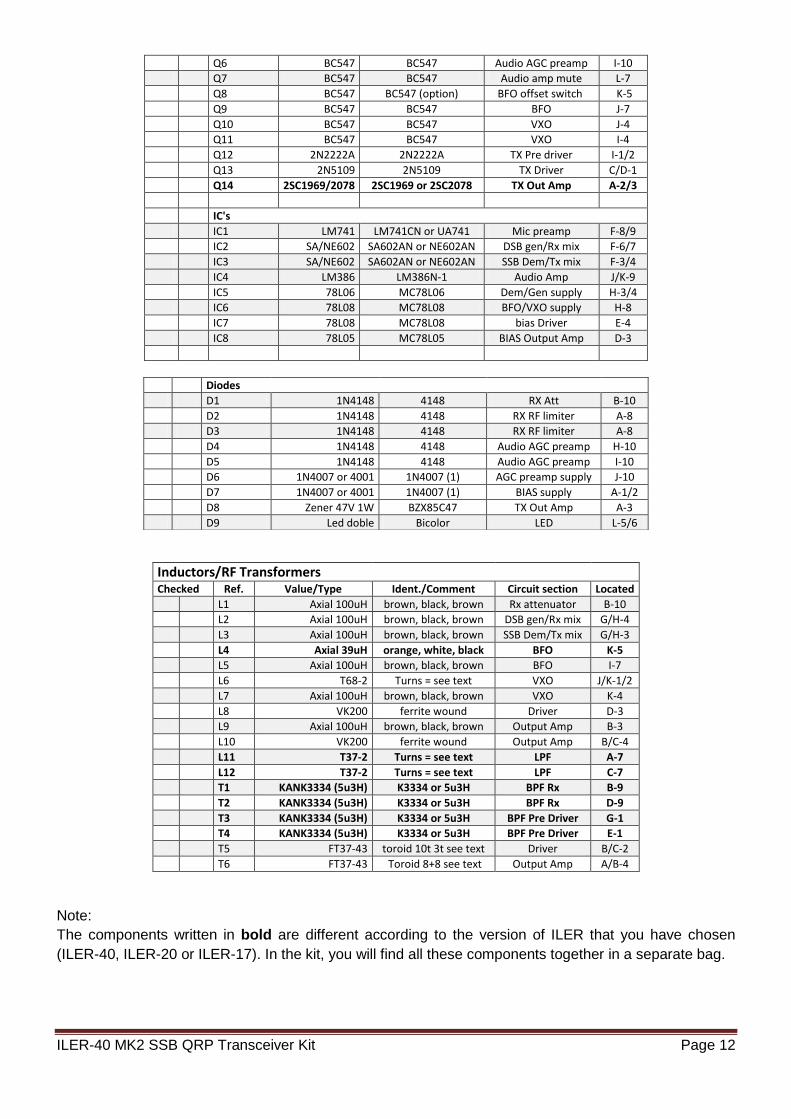
Inductors/RF Transformers
Checked Ref. Value/Type Ident./Comment Circuit section Located
L1 Axial 100uH brown, black, brown Rx attenuator B-10
L2 Axial 100uH brown, black, brown DSB gen/Rx mix G/H-4
L3 Axial 100uH brown, black, brown SSB Dem/Tx mix G/H-3
L4 Axial 39uH orange, white, black BFO K-5
L5 Axial 100uH brown, black, brown BFO I-7
L6 T68-2 Turns = see text VXO J/K-1/2
L7 Axial 100uH brown, black, brown VXO K-4
L8 VK200 ferrite wound Driver D-3
L9 Axial 100uH brown, black, brown Output Amp B-3
L10 VK200 ferrite wound Output Amp B/C-4
L11 T37-2 Turns = see text LPF A-7
L12 T37-2 Turns = see text LPF C-7
T1 KANK3334 (5u3H) K3334 or 5u3H BPF Rx B-9
T2 KANK3334 (5u3H) K3334 or 5u3H BPF Rx D-9
T3 KANK3334 (5u3H) K3334 or 5u3H BPF Pre Driver G-1
T4 KANK3334 (5u3H) K3334 or 5u3H BPF Pre Driver E-1
T5 FT37-43 toroid 10t 3t see text Driver B/C-2
T6 FT37-43 Toroid 8+8 see text Output Amp A/B-4
Note:
The components written in bold are different according to the version of ILER that you have chosen
(ILER-40, ILER-20 or ILER-17). In the kit, you will find all these components together in a separate bag.
Diodes
D1 1N4148 4148 RX Att B-10
D2 1N4148 4148 RX RF limiter A-8
D3 1N4148 4148 RX RF limiter A-8
D4 1N4148 4148 Audio AGC preamp H-10
D5 1N4148 4148 Audio AGC preamp I-10
D6 1N4007 or 4001 1N4007 (1) AGC preamp supply J-10
D7 1N4007 or 4001 1N4007 (1) BIAS supply A-1/2
D8 Zener 47V 1W BZX85C47 TX Out Amp A-3
D9 Led doble Bicolor LED L-5/6

ILER-40 MK2 SSB QRP Transceiver Kit Page 13
120-QUADRANT COMPONENT LAYOUT MAP

ILER-40 MK2 SSB QRP Transceiver Kit Page 14
ASSEMBLY
You can use the “individual parts list” or the “value/quantity parts list.” Using the “value/quantity parts list”
is the quickest way to mount components since all the circuit board components of the same value or
type can be placed one after the other. However, you will need the “individual parts list” to know how
each component is identified and its location on the circuit board. Depending on your personal
experience, you may prefer the individual parts list and feel more confident using it.
The 120-quadrant component layout map makes it very easy to find the location for all the components.
After mounting each component, it can be marked off in the “checked” column.
It is highly recommended that an inventory be taken of all the components to make sure that everything
is there and ready for assembly. Each constructor may have his/her own method of organizing the
components. One suggested method is to use a block of styrofoam packing material and poke the
components into it. The components can be sorted by type, value and size (ohms, micro-farads etc.).
RECOMMENDED ASSEMBLY SEQUENCE
Resistance and jumper LK
- The resistors are installed first. Mount all the resistors R1 to R65 and trimmers P2, P3 and P5. P4 is the
volume potentiometer, which will not be installed yet.
Refer to the parts list, and select the first resistor, R1. Bend the leads as close to the component body as
possible, and place them into the appropriate holes according to the component outline printed on the
circuit board. Be careful to avoid confusing the resistors with the axial inductors which are a bit thicker.
All of the resistors have a light-colored body and a gold band on one of the ends. Inserting the resistor
leads into the holes, push down on the body of the component so that it rests flat on the board, hold it in
place, and then slightly bend the leads to hold the resistor in place. Then turn the board over and solder
the leads to the printed circuit trace. Make sure that the resistor body lies flat on the board so that its
leads are as short as possible. Please read the notes about soldering, as poor soldering is the most
common cause for a kit failing to work for the first time. After soldering them, cut the excess length off
the component leads as close to the joint as possible. Mount the next resistor in the parts list in the same
manner and continue until all the resistors are mounted. Note that some resistors are mounted vertically;
bend the leads and insert them as shown in the pictures.
The values which are in decade increments can be easily confused, such as 470, 4K7 and 47K, so be
sure to verify the colors before soldering the component in place! If you are in doubt, use a multimeter to
check the resistor value.
- Bend a piece of leftover component lead and insert it into the jumper location marked as LK on the
circuit board (located between Q2 and the “12V” terminals).
ILER-40 MK2 SSB QRP Transceiver Kit Page 15
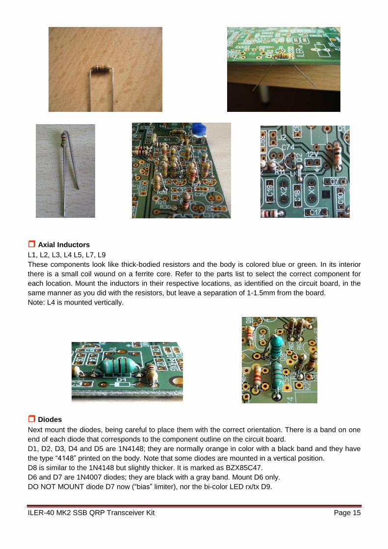
Axial Inductors
L1, L2, L3, L4 L5, L7, L9
These components look like thick-bodied resistors and the body is colored blue or green. In its interior
there is a small coil wound on a ferrite core. Refer to the parts list to select the correct component for
each location. Mount the inductors in their respective locations, as identified on the circuit board, in the
same manner as you did with the resistors, but leave a separation of 1-1.5mm from the board.
Note: L4 is mounted vertically.
Diodes
Next mount the diodes, being careful to place them with the correct orientation. There is a band on one
end of each diode that corresponds to the component outline on the circuit board.
D1, D2, D3, D4 and D5 are 1N4148; they are normally orange in color with a black band and they have
the type “4148” printed on the body. Note that some diodes are mounted in a vertical position.
D8 is similar to the 1N4148 but slightly thicker. It is marked as BZX85C47.
D6 and D7 are 1N4007 diodes; they are black with a gray band. Mount D6 only.
DO NOT MOUNT diode D7 now (“bias” limiter), nor the bi-color LED rx/tx D9.

ILER-40 MK2 SSB QRP Transceiver Kit Page 16
Capacitors
There are ceramic, polystyrene (styroflex) and electrolytic capacitors. They all have their value printed on
the body. Refer to the “identified” column in the parts list.
When you mount them, make sure to leave the leads as short as possible.
C79, C80 and C81 are polystyrene capacitors; these are axial capacitors, but they must be placed in a
vertical position.
The values which are in decade increments can be easily confused, such as 100n and 10n, so be sure
to verify the numbers of their value before soldering them in place!
The electrolytic capacitors must be placed with the correct orientation: the LONG LEAD goes in the hole
labeled “+” and the SHORT LEAD is "-", indicated by a band containing "-" signs on the side of the
capacitor.
CV1 is a trimmer capacitor which is black in color. It does not have printed numbers. Place it with the
rounded edge closest to the relay.
CV2 + CV3 are the same capacitor; it is a dual-section “Polyvaricon” variable tuning capacitor. DO NOT
INSTALL IT yet.
Radial Inductors VK200
L8 and L10 are broadband ferrite RF chokes; they are mounted in a vertical position.
Separate them approximately 0.5 - 1mm above the board to prevent the windings from touching any part
of the printed circuit.

ILER-40 MK2 SSB QRP Transceiver Kit Page 17
Pin "headers"
Place and solder the pins in Mic(3), 12V(2), ATT(2), P1-RXG(3), ANT(2), ALT(2), D7(2), VXO(2),
BFO(2), J1(3), J2(2), K1(1), K2(1), and S(2).
Place “jumpers” between pins “J2” and “J1-B” and between the active pins of “P1-RXG” (if RX gain
potentiometer is not used).
Turn the board over and insert and hold the header in place, using a “jumper” placed on the header while
you solder the pins to avoid burning your fingers. Use your other hand to hold the soldering iron and
move the board towards the solder to solder the headers in place. If you have someone available to help
you, it will be much easier!
Transistors
All of the transistors have their type printed on the component body. Place them according to the
corresponding component outline printed on the circuit board. Transistors Q1 through Q11 are all of the
type BC547. Q12 is a 2N2222 and Q13 is a 2N5109; these two transistors have a small tab that must
match up with the component outline printed on the circuit board. Mount them with 1.5-2mm separation
from the board. Mount the crown-like heatsink, which you will find in the kit's "hardware" bag, onto Q13.
Do not install Q14 (TX power amplifier) yet.

ILER-40 MK2 SSB QRP Transceiver Kit Page 18
Integrated circuits
The component outline for the IC on the circuit board has a “U” shaped notch on one end, indicating the
end at which pin 1 of the IC is located. There is a similar notch on one end of the sockets. This should be
oriented over the "U" notch outline on the circuit board. Finally, pin 1 of the IC is marked with a small
dimple or dot; this end of the IC should oriented towards the notch in the IC socket or the "U" on the
component outline.
Mount the sockets for IC1, IC2, IC3 and IC4 in the locations printed on the circuit board. Make sure that
the sockets lie flat against the circuit board.
Next, insert IC1, IC2, IC3 and IC4 into their respective sockets.
IMPORTANT: Make sure that the IC's are fully inserted into their sockets. A poor contact between the
socket and IC can cause malfunction of the kit.
Now, mount the voltage regulators IC5, IC6, IC7 and IC8 in their respective locations according to the
markings of the component outline on the circuit board.
Crystals
Install X1 through X7.
X1, X2, X3 and X4 are part of the SSB filter, and X5 is the oscillator crystal for the BFO. These crystals
have been hand-picked (they have handwritten numbers on them) and have the same resonant
frequency, in order to obtain the best filter quality. The pair X6 & X7 are the VXO crystals.
The crystal housing should not touch the board; place them slightly separated from the board, at a
distance of 0.5-1mm.
ILER-40 MK2 SSB QRP Transceiver Kit Page 19
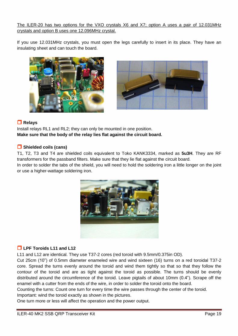
The ILER-20 has two options for the VXO crystals X6 and X7; option A uses a pair of 12.031MHz
crystals and option B uses one 12.096MHz crystal.
If you use 12.031MHz crystals, you must open the legs carefully to insert in its place. They have an
insulating sheet and can touch the board.
Relays
Install relays RL1 and RL2; they can only be mounted in one position.
Make sure that the body of the relay lies flat against the circuit board.
Shielded coils (cans)
T1, T2, T3 and T4 are shielded coils equivalent to Toko KANK3334, marked as 5u3H. They are RF
transformers for the passband filters. Make sure that they lie flat against the circuit board.
In order to solder the tabs of the shield, you will need to hold the soldering iron a little longer on the joint
or use a higher-wattage soldering iron.
LPF Toroids L11 and L12
L11 and L12 are identical. They use T37-2 cores (red toroid with 9.5mm/0.375in OD).
Cut 25cm (10”) of 0.5mm diameter enameled wire and wind sixteen (16) turns on a red toroidal T37-2
core. Spread the turns evenly around the toroid and wind them tightly so that so that they follow the
contour of the toroid and are as tight against the toroid as possible. The turns should be evenly
distributed around the circumference of the toroid. Leave pigtails of about 10mm (0.4”). Scrape off the
enamel with a cutter from the ends of the wire, in order to solder the toroid onto the board.
Counting the turns: Count one turn for every time the wire passes through the center of the toroid.
Important: wind the toroid exactly as shown in the pictures.
One turn more or less will affect the operation and the power output.

ILER-40 MK2 SSB QRP Transceiver Kit Page 20
Toroidal transformer T5
T5 is an impedance matching transformer. A FT37-43 is used (black toroid with 9.5mm/0.375in OD). It
has a 10-turn primary and a 3-turn secondary.
- Take 17cm (7.5”) of 0.5mm diameter enameled wire and wind ten (10) turns on a black FT37-43
toroidal core. Spread the turns evenly around the toroid and wind them tightly so that so that they follow
the contour of the toroid and are as tight against the toroid as possible. The turns should be evenly
distributed around the circumference of the toroid. Leave pigtails of 10-20mm (0.70”).
- Now take about 8cm (3.5”) of 0.5mm diameter enameled wire and wind three (3) turns on the other
side of the toroid, spacing the turns within the space between the turns of the previous winding. Leave
pigtails of 10-20mm (0.70”).
- Before inserting them on the circuit board, use a cutter or sandpaper to scrape off the enamel from the
pigtails of the windings. Solder them in place. Mount the toroid with approximately 0.5 - 1mm distance
from the board.
- The 3-turn winding is facing towards output transistor Q14 and the 10-turn winding towards C69 - C70.
Counting the turns: Count one turn for every time the wire passes through the center of the toroid.

ILER-40 MK2 SSB QRP Transceiver Kit Page 21
IMPORTANT: Wind the toroid exactly as shown in the pictures. You must pay attention to number of
turns as well as to the direction of the winding.
Toroidal transformer T6
T6 is an impedance matching transformer with a bifilar winding. A FT37-43 is used (black toroid with
9.5mm/0.375in OD). It has 8+8 turns.
- Cut a 31-32cm (12in) long piece of 0.5mm diameter enameled wire.
- Bend the wire in half.
- Twist it so that there are two or three twists per cm.
16cm (32 cm bent in half)
ILER-40 MK2 SSB QRP Transceiver Kit Page 22
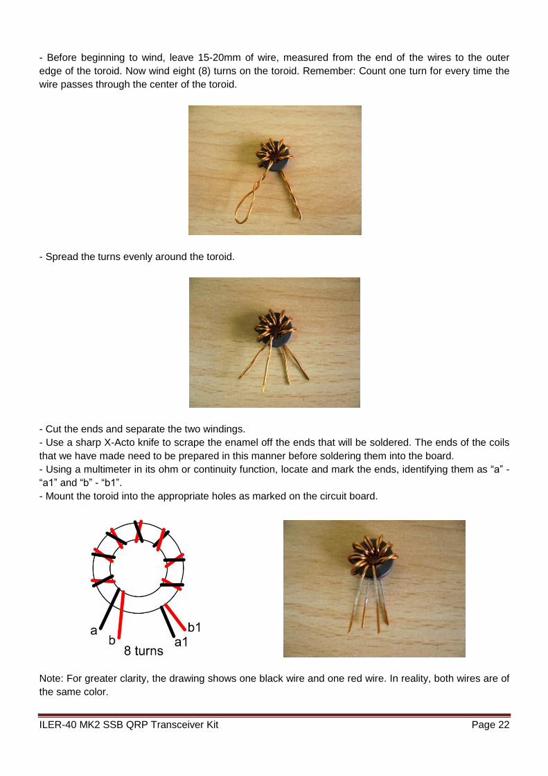
- Before beginning to wind, leave 15-20mm of wire, measured from the end of the wires to the outer
edge of the toroid. Now wind eight (8) turns on the toroid. Remember: Count one turn for every time the
wire passes through the center of the toroid.
- Spread the turns evenly around the toroid.
- Cut the ends and separate the two windings.
- Use a sharp X-Acto knife to scrape the enamel off the ends that will be soldered. The ends of the coils
that we have made need to be prepared in this manner before soldering them into the board.
- Using a multimeter in its ohm or continuity function, locate and mark the ends, identifying them as “a” -
“a1” and “b” - “b1”.
- Mount the toroid into the appropriate holes as marked on the circuit board.
Note: For greater clarity, the drawing shows one black wire and one red wire. In reality, both wires are of
the same color.

ILER-40 MK2 SSB QRP Transceiver Kit Page 23
VXO tuning Polyvaricon CV2/CV3
Install the hardware shaft onto the polyvaricon with the 12mm-long, M2.5 screw.
Mount the Polyvaricon with a separation of 2-3mm or more from the board (see picture). This makes it
easier to fit the variable cap to the front panel. Please, do not solder it until you are sure of how you are
going to mount the board into the box.
You may want to mount the polyvaricon off the board. This may be a good idea and there is no
objection to doing it, but use very short and slightly rigid wires. Even small movements may
affect the tuning!
This polyvaricon contains two variable tuning capacitor sections. By means of external jumpers J1 A/B,
you may select which section you will use; section CV2, which is the one with greater capacitance, is
selected by placing jumper “B”; section CV3, which has less capacitance, is selected by placing jumper
"A".
CV2 has about 160pF, CV3 has about 70pF.
In the back of the capacitor there are two padders (trimmers) for fine adjustment. The lower one is
parallel with CV2 (J1-B) and the top one is parallel with CV3 (J1-A). Adjusting these trimmers
changes the upper limit of band coverage by some 10-20 KHz! The upper limit adjustment must be
done with the polyvaricon at its minimum capacitance (turned completely clockwise).
For the ILER-40, jumper J1 must be placed in position B.
IMPORTANT: When screwing the polyvaricon to the front panel (M2.5 screws of 4mm) take care to not
drive the screws in too much, to avoid blocking the internal mechanism of polyvaricon. If needed, add
some washers to space the screws out from the panel to avoid this problem.
ILER-40 MK2 SSB QRP Transceiver Kit Page 24
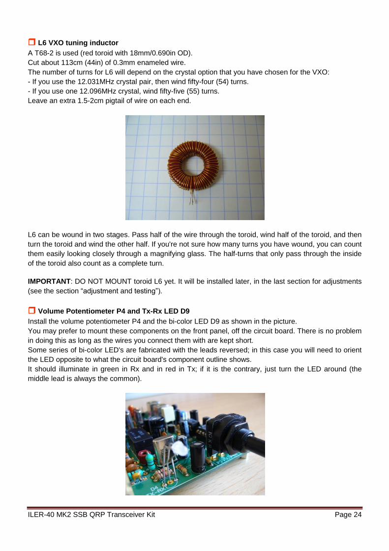
L6 VXO tuning inductor
A T68-2 is used (red toroid with 18mm/0.690in OD).
Cut about 113cm (44in) of 0.3mm enameled wire.
The number of turns for L6 will depend on the crystal option that you have chosen for the VXO:
- If you use the 12.031MHz crystal pair, then wind fifty-four (54) turns.
- If you use one 12.096MHz crystal, wind fifty-five (55) turns.
Leave an extra 1.5-2cm pigtail of wire on each end.
L6 can be wound in two stages. Pass half of the wire through the toroid, wind half of the toroid, and then
turn the toroid and wind the other half. If you're not sure how many turns you have wound, you can count
them easily looking closely through a magnifying glass. The half-turns that only pass through the inside
of the toroid also count as a complete turn.
IMPORTANT: DO NOT MOUNT toroid L6 yet. It will be installed later, in the last section for adjustments
(see the section “adjustment and testing”).
Volume Potentiometer P4 and Tx-Rx LED D9
Install the volume potentiometer P4 and the bi-color LED D9 as shown in the picture.
You may prefer to mount these components on the front panel, off the circuit board. There is no problem
in doing this as long as the wires you connect them with are kept short.
Some series of bi-color LED's are fabricated with the leads reversed; in this case you will need to orient
the LED opposite to what the circuit board's component outline shows.
It should illuminate in green in Rx and in red in Tx; if it is the contrary, just turn the LED around (the
middle lead is always the common).
ILER-40 MK2 SSB QRP Transceiver Kit Page 25
Jumpers "E-C-x-y", positioning of the Q14 and D7
The combination of jumpers “E-x-C-y” allows the use of different
types of transistors for Q14. If need be, we can use substitutes with
different lead configurations.
The ILER-40 kit uses a 2SC1969 or 2SC2078 for Q14 and the
following the jumpers SHOULD BE INSTALLED: “E-y” and “C-
x”. Cut small pieces of wire to make the connections "E" to "y" and
“C” to “x”.
Make sure that the wires do not touch each other.
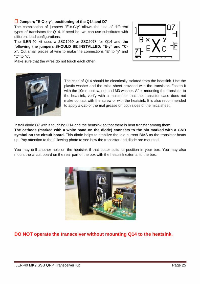
The case of Q14 should be electrically isolated from the heatsink. Use the
plastic washer and the mica sheet provided with the transistor. Fasten it
with the 10mm screw, nut and M3 washer. After mounting the transistor to
the heatsink, verify with a multimeter that the transistor case does not
make contact with the screw or with the heatsink. It is also recommended
to apply a dab of thermal grease on both sides of the mica sheet.
Install diode D7 with it touching Q14 and the heatsink so that there is heat transfer among them.
The cathode (marked with a white band on the diode) connects to the pin marked with a GND
symbol on the circuit board. This diode helps to stabilize the idle current BIAS as the transistor heats
up. Pay attention to the following photo to see how the transistor and diode are mounted.
You may drill another hole on the heatsink if that better suits its position in your box. You may also
mount the circuit board on the rear part of the box with the heatsink external to the box.
DO NOT operate the transceiver without mounting Q14 to the heatsink.

ILER-40 MK2 SSB QRP Transceiver Kit Page 26
Terminals “ATT” for enabling the RX attenuator
The header pins labeled “ATT” (located in quadrant D-10) can connect to a simple switch to activate the
receive attenuator.
The attenuation level is inversely proportional to the value of R1, which takes a part of the signal from
the antenna to ground. As you use the ILER-40, you may decide that you prefer a different level of
attenuation; simply replace R1 with the next value above or below that of the current resistance,
according to your wish.
The receiver can operate perfectly without using terminals “ATT”; however, it will not be able to reduce
the signal of the antenna input to compensate for very strong signals, and consequently it might produce
intermodulation distortion due to saturation of IC2.
If you frequently use the ILER-40 at different hours of the day and night, it might prove useful to add a
potentiometer for “RF Gain” at the terminals “P1RXG”, with which you can adjust the attenuation level at
the RX input according to what is most appropriate for each situation.
Terminals “P1RXG” for connecting a RX attenuator potentiometer (optional)
The header pins P1RXG can connect to a 1K linear potentiometer for adjusting to the most appropriate
attenuation level at the moment. This potentiometer is optional and is not included with kit. For
connection details, see the corresponding Appendix in the additional documentation.
If not using the P1, remember to place a “jumper” (bridge) among active terminals.
Terminal “K1” for carrier generation
The header pin marked "K1" is located in quadrant D-6.
This terminal is provided for generating a carrier for testing, transmitter adjustments, adjusting antenna
couplers, etc. It can also be used to operate the ILER-40 in CW mode (see Appendix in the additional
documentation).
Connecting terminal K1 to +V during transmission, unbalances the modulator and a carrier is generated.
Terminal “K2” BFO offset for CW (occasional)
The terminal marked "K2" is located in quadrant L-4.
This terminal is provided to shift the BFO during transmit by several hundreds of Hertz to use the ILER-
40 in CW mode. To operate in CW, the K2 terminal stays connected to +V during RX and is
disconnected during TX (see Appendix in the additional documentation).
Important:
- Note that to operate in CW mode, the switching of K1 and K2 connections operates opposite each
other. For more details, see the corresponding Appendix in the additional documentation.
- The ILER-40 is not specifically designed for operating in CW. However, K1 and K2 allow CW
operation on an occasional basis, for tests or in case of emergency.
- To operate only in SSB, no connection to K1 or K2 is necessary.
- All of the adjustments mentioned in this manual are for operating
in SSB.

ILER-40 MK2 SSB QRP Transceiver Kit Page 27
ADJUSTMENTS AND TESTS
Preliminary Testing
- Adjust P3 (carrier suppression), P4 (volume potentiometer), and P5 (bias adjustment) to mid-position.
- Adjust P2 (mic gain) to minimum position (counterclockwise).
- Connect a speaker or headphones to the “ALT” pins on the circuit board.
IMPORTANT: Use a high-quality speaker box. A bad speaker will make ineffective the operation of the
transceiver.
- DO NOT yet connect a microphone.
- Apply power supply voltage (12-14V) to the “12V” header pins on the circuit board.
- Measure the voltage at the following main points:
Rx-Tx LED illuminated green (some LED's have the leads reversed; turn it around if it is red in Rx).
8V on any lead of L5 or L7 to ground.
6V on any lead of L2 or L3 to ground.
- Turn the volume to maximum; you should hear a hissing noise in the headphones or speaker.
If everything is okay, you may continue.
If something is not right, you will need to examine it. (see the section, “If your kit does not work after
assembly").
Adjustment of the VXO Tuning Inductor L6 and Polyvaricon CV2/CV3
The following work is usually more enjoyable than what it appears at first; it is not “plug & play”. Look for
a few hours when you are not in a hurry. Take your time and enjoy yourself!
Solder the pigtails of L6 in place on the circuit board. Leave them a little long (5-6mm) for the moment,
so that you can compress or spread the turns. Connect a frequency counter to the “VXO” header. If the
input of the frequency counter is low impedance, insert a 470 ohm (or greater) or a small value capacitor
(try with 22pF or less) between the frequency counter and the header to reduce the interaction with the
VXO.
If you don't have access to a frequency counter, you may use a high-quality SSB or CW receiver that
covers the VXO frequency (12.000MHz) and that has digital frequency readout. Connect to the receiver
antenna input a piece of wire with a small loop and place it close to the VXO.
Note: Use of a frequency counter is highly recommended for this adjustment, as the use of a receiver is
very cumbersome.
The IF frequency of 4.915MHz is substract to the VXO frequency, for example of 12.010MHz, to obtain
the operating frequency of 7.095MHz (VXO crystals option=12.031MHz). Another example would be IF
4.915MHz and VXO 12.065MHz = 7.150MHz (VXO crystal option of 12.098MHz).
Spreading or compressing the turns changes the range of coverage. Compressing the turns increases
the inductance, thus increasing the frequency range. If the turns are spread, the inductance and thus the
frequency coverage decreases. Spreading or compressing the turns very little achieves a variation of a
few Khz.
The polyvaricon contains two variable tuning capacitor sections. J1 selects which section is used.
Placing jumper “B” selects the section with more capacitance, CV2 (160pf); placing jumper “A” selects
the section with less capacitance, CV3 (70pf).
The following illustrative table uses J1 with a jumper in position B and the turns on L6 moderately
compressed (this is the configuration that I recommend for the ILER-40):
For the ILER-40, jumper J1 should be placed in position B.

ILER-40 MK2 SSB QRP Transceiver Kit Page 28
Option X6-X7 = 12.031Mhz.
J1-B T68-2= 54 turns Maximum Minimum
X6-X7 = 12.031Mhz. MHz MHz MHz MHz
VXO RF VXO RF Coverage
12.020 7.105 11.955 7.040 65Khz
Option X7 = 12.096Mhz.
J1-B T68-2= 55 turns Maximum Minimum
X7 = 12.096Mhz. MHz MHz MHz MHz
VXO RF VXO RF Coverage
12.085 7.170 12.015 7.100 70Khz
Values are strictly illustrative. They will be influenced by the number of turns on L6, the rear fine tuning
trimmer adjustment and the component tolerances.
Upper frequency limit adjustment.
In the back of the polyvaricon there are two padders (trimmers) for fine adjustment. The lower one is
parallel with CV2 (J1-B) and the top one is parallel with CV3 (J1-A). In the ILER-40 the lower trimmer is
used. This adjustment allows setting the upper frequency limit within a range of more than 10
KHz!
Make this adjustment with the polyvaricon at its minimum capacitance (completely clockwise).
In the ILER-40 try locating the padder (trimmer) at its minimum capacitance (completely open) to obtain
the highest possible upper limit.
In the case that, even after spreading the turns to the maximum the range is very large, or compressing
them the range is very small, you can take off or add a turn to L6. (one more turn = more range; one less
turn = less range).
Once you are sure that the VXO range will suit your needs, you will need to secure L6 in position on the
board. I suggest two options:
1) Use a little bit of wax or hot glue (that doesn't contain water) to secure it in the place. Then you may
also use a fine layer of nail polish to fix the turns.
Caution: Some glues, due to their composition, may greatly affect the characteristics of L6, even after
curing. You may find that once you have secured inductor L6, the VXO frequency has changed
considerably in relation to the adjustments that were made before. They can also absorb more or less
humidity, affecting the stability.

ILER-40 MK2 SSB QRP Transceiver Kit Page 29
2) The most effective and cleanest option is to use a small plastic tie-wrap, passing it through the
holes in the circuit board as showing in the picture.
Once the tie-wrap is fully tightened, you will still be able to move the turns slightly and make slight
adjustments before securing them with a little bit of nail polish.
L6 should be well secured; this is very important, since vibrations may change the VXO frequency,
causing frequency "flutter" in the received and transmitted signals.
IMPORTANT: Prior to permanently securing L6, make all of the transceiver adjustments and checks and
confirm that the frequency coverage suits your needs.
I recommend this number of turns and type of toroid for L6. It works well! However, you can modify and
experiment with the inductance to try a different coverage. More inductance will increase the coverage
but reduce the stability and the VXO may even stop oscillating, and vice versa.
In order to obtain good stability, a maximum coverage of 50-60 KHz is
recommended. In addition, a wide coverage will make tuning difficult, and it will be necessary to add a fine tuning control
by using gear reduction on the polyvaricon, a second variable capacitor or a varactor diode.
Do not worry too much about obtaining exact coverage down to the KHz. Is it so important to end up with
60, 59 or 61 KHz?
If you have graphical ability, you can draw a dial on the front panel with a frequency scale to serve as a
guide.
In order to put us in other segments of the band different from those specified here, you will need to use
VXO crystals with different frequencies.
Adjustment of the BFO/Carrier Oscillator
There are two ways to adjust the BFO oscillator frequency.
- Adjustment without instrumentation:
Turn on the transceiver. Leave it on for about 5 minutes.
You can adjust CV1 while listening to a LSB signal on the 40 meter band. This is a “two-hand” operation;
tune the VXO to obtain the best possible intelligibility, and next adjust CV1 to obtaining the best possible
audio quality. Repeat these adjustments until obtaining the best possible results.

ILER-40 MK2 SSB QRP Transceiver Kit Page 30
- Adjustment with instrumentation (requires a frequency counter):
Turn on the transceiver. Leave it on for about 5 minutes. Connect the frequency counter to the “BFO”
header. If the input of the frequency counter is low impedance, insert a 470 ohm (or greater) resistor or a
small value capacitor (try 22pF or less) between the frequency counter and the header to reduce the
interaction with the BFO.
Adjust CV1 for a frequency of 4.913.5 MHz. You may readjust it slightly later if needed.
The total range of the CV1/BFO is approximately 4.912.8 to 4.914.5 MHz. The capacitance of the
trimmer goes from maximum to minimum in a ½ turn (180 degrees). If you look inside the adjustment
hole, you will see that there is an arrow to one side or other of the travel. When the arrow points to the
flat part of trimmer, the capacitance is at minimum.
Note: The BFO adjustment is important for reception, but even more so for transmission, as it
substantially influences the modulation quality as well as the output power. The signal may sound too
sharp and tinny or very bassy and muffled.
Adjustment of the RX pass band, T1 and T2
Note: For this adjustment you will need an “alignment” tool suitable for this type of coils; if you use a
screwdriver, you risk of breaking the core of the coil.
With an antenna connected to the transceiver, alternately adjust T1 and T2 until obtaining the maximum
level of noise in the speaker. Now, try to tune in a stable signal within the band and readjust T1 and T2
alternatively until you hear it at the highest possible level.
If you have access to an RF generator, begin injecting a signal of about 1uV within the frequency
coverage of receiver and tune it in. Reduce the level of the RF generator to the minimum that is still
audible with a loudspeaker or headphones, and alternately adjust T1 and T2 until obtaining the
maximum reception level.
Once you have finished all of the adjustments and tests for the ILER-40, you may make a slight
readjustment of the reception if you wish.
REMEMBER: All transmission tests should be done with a 50 ohm load connected to the
transmitter output. DO NOT OPERATE the transmitter without a heatsink attached to Q14.
Adjustment of the idle current of the TX output transistor Q14
Although this adjustment is not critical, it is important to do it with the transistor cool.
Adjust P2 (mic gain) to minimum position (counterclockwise). Remove jumper J2. Adjust P5 (“BIAS”
adjustment) to the center of its range.
Connect a multimeter in its position for measuring current on the 200mA scale in series with the pins of
J2. Activate the PTT or put a jumper between the PTT pin and ground; adjust P5 to obtain about 45mA
on the meter.
As transistor Q14 is heating up, it is normal for this value to increase.
If you don't have a meter for measuring milliamperes, adjust P5 to about 75% of its range (going
clockwise); this position will be within the correct margin.
After finishing the adjustment, return jumper J2 to its position and readjust P2 (mic gain).

ILER-40 MK2 SSB QRP Transceiver Kit Page 31
Adjustment of the TX passband, T3 and T4
Note: For this adjustment you will need an “alignment” tool suitable for this type of coils; if you use a
screwdriver, you risk of breaking the core of the coil.
Connect a power meter with a 50 ohm load to the antenna jack.
I suggest two options for adjusting the transmitter passband:
1) If you have access to an audio generator, set the mic gain (P2) to half range and injects a signal of
around 800-1000Hz. at about 20mV into the mic input; put the transceiver in transmit mode (PTT pin to
“GND”) and alternately adjust T3 and T4 until obtaining to the maximum power reading on the power
meter.
2) If you don't have access to instrumentation, connect a wire from header pin “K1” to positive +12V and
puts the transceiver in transmit (pin PTT to GND). This will cause the modulator to generate a carrier;
alternately adjust T3 and T4 until obtaining the maximum power level possible on the power meter (you
will not obtain the maximum power until connecting the microphone). After finishing the
adjustment, disconnect the wire from pin “K1”.
Adjustment of the Balanced modulator (carrier suppression)
Adjust P2 (mic gain) to minimum (counterclockwise). Adjust P3 to mid-position.
Connect the power supply. Let the transceiver warm up for about 5 minutes.
Now, activate the PTT pin of the mic and monitor the transmitter output with an oscilloscope (with a 50
ohm load connected). Adjust P3 to obtain the minimum level possible of residual carrier signal.
If you don't have access to an oscilloscope, you may listen to the transmitted signal on a SSB/CW
receiver; adjust P3 until you hear the least possible amount of carrier signal. Keep in mind that with a
receiver so close, you will ALWAYS hear a weak residual signal.
IMPORTANT: The ILER-40 mic input is quite sensitive and offers very comfortable operation and good
modulation quality. Use of a classic dynamic microphone, such as those used for CB's, is recommended.
In order to use an electret microphone, a small adaptor circuit will need to be used (see the Appendix in
the additional documentation).
The use of amplified microphones is not recommended.
Just as choosing a good speaker is important for reception, be careful with the type of microphone that
you use and with the gain adjustment; an unsuitable microphone or excessive gain can ruin the
transmission quality.
Adjustment of mic gain P2
Adjustment with instrumentation.
Connect the 50 ohm load and power meter to the antenna jack. Adjust P2 (mic gain) to its mid-position.
Connect the microphone to the mic input and press the PTT to go to transmit. (TX = PTT to “GND”)
Connect an oscilloscope to the antenna jack (along with a 50 ohm load). Adjust the transceiver to see
the signal envelope and, speaking loudly into the microphone, adjust P2 just to the point before seeing
distortion on the waveform.

ILER-40 MK2 SSB QRP Transceiver Kit Page 32
If you don't have access to instrumentation, speak or whistle into microphone and adjust P2 so that you
obtain the maximum power level of power on the power meter. P2 should be adjusted just to the point at
which maximum power is obtained or a little less.
This adjustment will be a little ambiguous, since it depends a lot on the operator's type of voice and way
of speaking. Use the “cut and try” method.
It is recommended that you request a fellow operator to critique your modulation.
Note: For very sharp or very bassy voices, you may slightly readjust the BFO to obtain the best level of
output power.
IF YOUR KIT DOES NOT WORK AFTER ASSEMBLY Don't worry, it is not uncommon that a kit doesn't work on the first try; stay calm, as in most cases they
are minor problems with a simple fix.
Most of faults are due to poorly soldered connections or misplaced components; it is very rare to find a
faulty component. Before taking any measurements with test equipment, check all the connections and
carefully inspect your soldering, looking for cold joints, short circuits between traces, sockets not making
good contact, or components mounted in the wrong place.
If your kit does not work after final assembly, please follow these steps in order:
- Double-check every step in the assembly manual, the solder connections, and correct component
placement.
- If you have access to instrumentation, take measurements and follow the signal path of the circuits to
diagnose what is happening and why.
- Request another ham experienced with kits or a radio technician to check your work. Someone taking a
fresh look may find things that you overlooked.
- If you decide that technical assistance is needed, you are welcome to send an email to
[email protected]. As a last resource, you may send the kit in for repair; however, I will have to charge
for any repairs done, although I will try to keep the cost as moderate as possible.
To help troubleshoot your transceiver, the following voltage table may be useful. The IC and transistor
voltages were measured in receive and transmit (without modulation). If there is a fault, it is quite likely
that one or more of the readings will be very different.
IC Ref. Type pin1 Rx pin1 Tx pin2 Rx pin2 Tx pin3 Rx pin3 Tx pin4 Rx pin4 Tx IC1 LM741 0 0 0 6.63 0 6.65 0 0
IC2 SA602 1.26 1.26 1.26 1.26 0 0 5 5.01
IC3 SA602 1.38 1.38 1.38 1.38 0 0 4.72 4.67
IC4 LM386 1.3 0 0 0 0 0 0 0
IC5 78L06 Out.=6V -- -- -- -- -- -- --
C6 78L08 Out.=8V --- -- -- -- -- -- --
IC7 78L08 Out.=8V -- -- -- -- -- -- --
IC8 78L05 Out.=5V -- -- -- -- -- -- --

ILER-40 MK2 SSB QRP Transceiver Kit Page 33
IC Ref. Type pin5 Rx pin5 Tx pin6 Rx pin6 Tx pin7 Rx pin7 Tx pin8 Rx pin8 Tx
IC1 LM741 0 0 0 6.67 0.06 13.35 0.06 0
IC2 SA602 5.04 5 5.86 5.86 5.37 5.1 5.92 5.92
IC3 SA602 4.74 4.75 5.81 5.81 5.05 5.34 5.87 5.87
IC4 LM386 4.55 0 13.5 0.07 6.72 0 1.29 0
Transistor Ref. Type B Rx B Tx E Rx E Tx C Rx C Tx
Q1 BC547 0 0.78 0 0 0 0
Q2 BC547 3.8 3.8 3.92 3.92 7.95 7.95
Q3 BC547 3.5 3.5 4.01 4.01 7.95 7.95
Q4 BC547 3.85 3.85 3.67 3.67 7.95 7.95
Q5 BC547
Q6 BC547
Q7 BC547
Q8 BC547
Q9 BC547
Q10 BC547
Q11 BC547
Q12 2N2222
Q13 2N5190
Q14 2SC1969
VCC = 13.5V Approximate values of +/-10% can be considered correct.

ILER-40 MK2 SSB QRP Transceiver Kit Page 34
LIMITED WARRANTY Please read carefully BEFORE building your kit
All electronic components and hardware supplied with the kit are under warranty in case of any
manufacturing defect for the period of one year after purchase. The warranty does not include the
transmitter final amplifier transistor.
The original purchaser has the option of examining the kit and manual for 10 days. If, within this period,
the buyer decides not to build the kit, he/she may return the entire unassembled kit at their own expense
for the shipping expenses. The shipping expenses and sales commissions (i.e. bank, Ebay, and Paypal
commissions) included in the purchase price will not be returned.
Please, BEFORE returning a product, request instructions by email at: [email protected]
Javier Solans, EA3GCY, warrants this device to function according to the specifications, provided that it
is assembled and adjusted as described in this documentation, and used correctly according to all
provided instructions.
It is your responsibility to follow all the instructions in the manual, to identify all the components correctly,
and to use good workmanship and proper tools and instruments in the construction and adjustment of
this kit.
REMEMBER: This kit will not work as a commercially manufactured product; however, if can often give
similar results. Do not expect great performance, BUT YOU ARE SURE TO HAVE LOTS OF FUN!
If you believe that there is a missing component for the kit, please do a thorough inventory of all parts
using the parts list in the manual. Check all bags, envelopes and boxes carefully. If needed, you may
email me and I will replace any component that you are missing. Even if you can find the exact part
locally, please let me know so that we are aware of the problem to help other customers.
I can also supply any part that you have lost, damaged or broken accidently.
If you find any errors in this manual or would like to make a comment, please do not hesitate to contact
me at: [email protected]
THANK YOU for building the ILER-40 MK2 SSB Transceiver kit.
Enjoy QRP!
73 Javier Solans, EA3GCY

ILER-40 MK2 SSB QRP Transceiver Kit Page 35
SCHEMATIC

ILER-40 MK2 SSB QRP Transceiver Kit Page 36
WIRING
The ILER-40 wiring is very simple, as long as you remember that:
- For the antenna connection use a thin, RF-rated coaxial cable such as RG-174 or similar.
- If you install the tuning polyvaricon off the circuit board, you should use short and stiff wires, as the
mechanical stability is very important.
-A metal box is highly recommended.
The ILER-40 is not protected against reverse polarity!
It is a good idea is to place a diode (i.e. BY255 or larger) in parallel with the power supply input. The
cathode (the end of the diode with the printed band) goes to the positive wire. If your power supply has
short-circuit protection or has a fuse on its output, fine; otherwise, you will need to build or buy a cable
with an in-line fuse in series.