ijrmet vo l . 4, issu e 2, spl - 2 may - o 2014 ... · pdf filethe rsm is a dynamic and...
TRANSCRIPT

IJRMET Vol. 4, IssuE 2, spl - 2 May - ocTobER 2014
w w w . i j r m e t . c o m InternatIonal Journal of research In MechanIcal engIneerIng & technology 127
ISSN : 2249-5762 (Online) | ISSN : 2249-5770 (Print)
Optimization of Machining Parameters for MRR in Boring Operation Using RSM
1Gaurav Bansal, 2Harsimran Singh Sodhi, 3Jasmeet Singh1Dept. of Mechanical Engineering, RIMT Polytechnic College, Mandi-Gobindgarh, India
2Dept. of Mechanical Engineering, Chandigarh University, India3Dept. of Mechanical Engineering, Desh Bhagat Engineering College, Punjab, India
AbstractIn any machining process, apart from obtaining the accurate dimensions, achieving maximized metal removal are also of utmost importance. A machining process involves many process parameters which directly or indirectly influence the metal removal rate of the product in common. Metal removal in machining process is varied due to various parameters of which feed, speed, depth of cut are important ones. A precise knowledge of these optimum parameters would facilitate reduce the machining costs. Extensive study has been conducted in the past to optimize the process parameters in any machining process to have the best product. Current investigation is made on boring process and Response Surface Methodology is applied on the most effective process parameters i.e. feed, cutting speed and depth of cut while machining AISI 4130 steel alloy. The main effects (independent parameters), surface plots and contour plots of the variables have been considered separately to build best subset of the model. Each boring parameter is considered at two levels. After having the data from the experiments, the performance measures MRR is calculated using the existing formulae. To analyze the data set, MINITAB-16 (Software) has been used to reduce the manipulation and help to arrive at proper improvement plan of the Manufacturing process & Techniques.The results of analysis show that feed rate and cutting speeds have present significant contribution on the material removal rate and depth of cut have less significant contribution on the material removal rate.
KeywordsOptimization, Boring Parameters, Material Removal Rate, Response Surface Methodology.
I. IntroductionIn present manufacturing scenario the quality and quantity are two challenging aspects, which are to be looked upon. Quantity is required for the industrial point of view to maximize the profit earnings. So, material removal rate is a major consideration in modern industry. Machining is a manufacturing process in which unwanted material is removed from the work piece to get the desired shape and dimensions. Machining operations have been the core of the manufacturing industry since the industrial revolution.The RSM is a dynamic and foremost important tool of Design of Experiment (DOE) where in the relationship between process output(s) and its input decision variables, it is mapped to achieve the objective of maximization or minimization of the output properties.
A. Boring ProcessIn machining, boring is the process of enlarging a hole that has already been drilled (or cast), by means of a single-point cutting tool (or of a boring head containing several such tools), for example as in boring a cannon barrel. Boring is used to achieve
greater accuracy of the diameter of a hole, and can be used to cut a tapered hole. Boring can be viewed as the internal-diameter counterpart to turning, which cuts external diameters.
Fig. 1: Boring Process
There are various types of boring. The boring bar may be supported on both ends (which only works if the existing hole is a through hole), or it may be supported at one end. Line boring (line boring, line-boring) implies the former. Back boring (back boring, back-boring) is the process of reaching through an existing hole and then boring on the “back” side of the work piece (relative to the machine headstock). Because of the limitations on tooling design imposed by the fact that the work piece mostly surrounds the tool, boring is inherently somewhat more challenging than turning, in terms of decreased tool holding rigidity, increased clearance angle requirements (limiting the amount of support that can be given to the cutting edge). These are the reasons why boring is viewed as an area of machining practice in its own right, separate from turning, with its own tips, tricks, challenges, and body of expertise, despite the fact that they are in some ways identical
II. Literature ReviewMany researchers have been carried out experimental investigations over the years in order to study the effect of cutting parameters, tool geometries on the work pieces surface integrity using several types of work piece materials. Traditionally, the selection of cutting conditions for metal cutting is left to the machine operator. In such cases, the experience of the operator plays a major role, but even for a skilled operator it is very difficult to attain the optimum values each time. The main machining parameters in metal boring operations are cutting speed, feed rate and depth of cut etc. The setting of these parameters determines the quality

IJRMET Vol. 4, IssuE 2, spl- 2 May - ocTobER 2014 ISSN : 2249-5762 (Online) | ISSN : 2249-5770 (Print)
w w w . i j r m e t . c o m 128 InternatIonal Journal of research In MechanIcal engIneerIng & technology
characteristics of machined parts. K. Palani Kumar, et al.[2] Upinder Kumar Yadav*, Deepak Narang**, Pankaj Sharma Attri[4]** The aim of this experiment was to evaluate the effects of the process parameters on AISI 304 austenitic stainless steel work piece for surface roughness and material removal rate by employing Analysis of Variance using PVD coated cement tool on CNC lathe under dry environment. H. K. Dave, L. S. Patel, H. K. Raval et al.(2012) [3] have been investigation of the machining characteristics of different grades of EN materials in CNC turning process using Tin coated cutting tools. In this research paper focused on the analysis of optimum cutting conditions to get the maximum material removal rate in CNC turning of different grades of EN materials by Taguchi method. It have been found that ANOVA shown that the depth of cut has significant role to play in producing higher MRR.
III. Experimental ProcedureTHE STUDY HAS BEEN PERFORMED ON AISI 4130 STEEL ALLOY BARS HAVING DIMENSIONS OF 40 MM DIAMETER AND 40 MM LENGTH, ON CNC BORING MACHINE BY USING CARBIDE TOOL OF 0.6 MM NOSE RADIUS.Further the work has been channelized through following adopted procedure:
Check and prepare the CNC Boring Machine (Lokesh TL • 250) ready for performing the machining operation.Cut the work piece by power saw and perform initial boring • operation on simple lathe to get desired dimensions of work pieces.Calculate weight of each specimen by high precision Digital • Balance Meter (DBM) before machiningPerform straight boring operation on specimens in various • cutting environments involving various combinations of process control parameters like: spindle speed, feed and depth of cut etc. These experiments are pre designed with RSM using MINITAB software and executed as per orthogonal matrix provided by RSM technique.Calculate the weight of each machined bar again by DBM • and assessed the material removal rate suitably.
A. Parameters & Their LimitsTable 1: Process Parameter LevelsProcess Variable Unit Level 1 Level 2Cutting Speed m/min. 100 200Feed Rate mm/rev. 0.08 0.18Depth of cut mm 1 2
Now, RSM matrix is made using MINITAB software. 20 no. of observations were found and experiments are performed on the same and material removal rate is determined. Table 2 shows the resultant matrix and material removal rate.
Table 2: Experiment Results
Sr No. Cutting Speed Feed rate Depth of
cut MRR (mm3/min)
1 150 0.13 1.5 121.922 150 0.13 1.5 119.123 65.9103 0.13 1.5 86.724 200 0.18 1 149.955 200 0.08 1 89.316 150 0.13 0.6591 82.877 150 0.13 1.5 135.36
8 200 0.18 2 166.329 150 0.13 1.5 112.3510 200 0.08 2 135.7411 150 0.13 2.3408 144.2312 150 0.2140 1.5 175.6313 100 0.18 1 118.3214 150 0.13 1.5 130.2515 100 0.08 2 103.2516 150 0.13 1.5 133.2017 100 0.08 1 47.4618 100 0.18 2 144.5219 150 0.0459 1.5 70.9320 234.0896 0.13 1.5 157.11
IV. Results & DiscussionNow, various set of analysis is made to validate the results.
1050-5-10
99
90
50
10
1
Residual
Pe
rce
nt
15010050
10
5
0
-5
-10
Fitted Value
Re
sid
ua
l
1050-5-10
6.0
4.5
3.0
1.5
0.0
Residual
Fre
qu
en
cy
2018161412108642
10
5
0
-5
-10
Observation Order
Re
sid
ua
l
Normal Probability Plot Versus Fits
Histogram Versus Order
Residual Plots for MRR (mm³/min)Ra(µm)
Fig. 2: Residual Analysis of MRR
Table 3: Estimated Regression Coefficients for MRRTerm Coef SECoef T PConstant 125.363 3.146 39.850 0.000Cutting Speed 30.316 3.510 8.636 0.000Feed rate 46.723 3.510 13.311 0.000Depth of Cut 30.537 3.510 8.699 0.000Cutting Speed*Cutting Speed
-3.371 5.747 -0.587 0.037
Feed rate*Feed rate -2.010 5.747 -0.350 0.734
Depth of Cut*Depth of Cut -11.738 5.747 -2.042 0.028
Cutting Speed*Feed rate -7.398 7.713 -0.959 0.039
Cutting Speed*Depth of Cut
-6.785 7.713 -0.880 0.400
Feed rate*Depth of Cut -21.090 7.713 -2.734 0.021
S = 7.71322 PRESS = 2023.22
R-Sq = 97.15% R-Sq(pred) = 90.31% R-Sq(adj) = 94.59%

IJRMET Vol. 4, IssuE 2, spl - 2 May - ocTobER 2014
w w w . i j r m e t . c o m InternatIonal Journal of research In MechanIcal engIneerIng & technology 129
ISSN : 2249-5762 (Online) | ISSN : 2249-5770 (Print)
Table 4: ANNOVA Table to check RSM statics for MRR
Source DOF Seq SS Adj SS Adj MS F P
Regression 9 20284.1 20284.1 2253.8 37.88 0.00Linear 3 19480.8 19480.8 6493.6 109.15 0.00Square 3 257.8 257.8 85.9 1.44 0.288Interaction 3 545.5 545.5 181.8 3.06 0.078Residual Error 10 594.9 594.9 59.5
Lack of fit 5 189.5 189.5 37.9 0.47 0.788Pure Error 5 405.4 405.4 81.1Total 19 20879.1
Figs. 2 show the residual distribution diagrams for MRR. These are generally fall on a straight line implying that errors are distributed normally. From Fig. it can be concluded that all the values are within the CI level of 95 %. Hence, these values yield better results in future prediction. Fig. indicated that there is no obvious pattern and unusual structure. So, it can be conclude that the residual analysis does not indicate any model inadequacy. The purpose of analysis of variance is to investigate which design parameter significantly affects the material removal rate.
A. Interpretation of Plots The plots are developed with the help of a software package MINITAB 16. The purpose of main effect plot is to obtain a general idea of which main effect may be important. Fig. 3 shows the main effects plot for MRR.
234.090200.000150.000100.00065.910
180
150
120
90
600.2140900.1800000.1300000.0800000.045910
2.340902.000001.500001.000000.65910
180
150
120
90
60
Cutting Speed
Mea
n
Feed rate
Depth of Cut
Main Effects Plot for MRR (mm³/min)Data Means
Fig. 3: Effect of Boring Parameters on MRR
250
20050150
100
150
1001.01.5
2.02.5
MRR (mm³/min)
Cutting Speed
Depth of Cut
Feed rate 0.13Hold Values
Surface Plot of MRR (mm³/min) vs Cutting Speed, Depth of Cut
Fig. 4: Surface Plot of MRR vs Cutting Speed & Depth of Cut
Depth of Cut
Cu
ttin
g S
pe
ed
2.22.01.81.61.41.21.00.8
220
200
180
160
140
120
100
80
Feed rate 0.13Hold Values
> – – – – < 50
50 7575 100
100 125125 150
150
(mm³/min)MRR
Contour Plot of MRR (mm³/min) vs Cutting Speed, Depth of Cut
Fig. 4(a): Contour Plot of MRR vs cutting speed & Depth of cut
250
20050150
100
150
0.05
200
1000.10
0.15 0.20
MRR (mm³/min)
Cutting Speed
Feed rate
Depth of Cut 1.5Hold Values
Surface Plot of MRR (mm³/min) vs Cutting Speed, Feed rate
Fig. 5 Surface plot of MRR vs Cutting speed & Feed rate
Feed rate
Cutt
ing
Spee
d
0.2000.1750.1500.1250.1000.0750.050
220
200
180
160
140
120
100
80
Depth of Cut 1.5Hold Values
> – – – – – < 50
50 7575 100
100 125125 150150 175
175
(mm³/min)MRR
Contour Plot of MRR (mm³/min) vs Cutting Speed, Feed rate
Fig. 5-a Contour Plot of MRR vs Cutting speed & feed rate
0.20
0.150
50
100
0.10
150
1.0 1.5 0.052.0 2.5
MRR (mm³/min)
Feed rate
Depth of Cut
Cutting Speed 150Hold Values
Surface Plot of MRR (mm³/min) vs Feed rate, Depth of Cut
Fig. 6: Surface Plot of MRR vs Feed rate & Depth of cut
IJRMET Vol. 4, IssuE 2, spl- 2 May - ocTobER 2014 ISSN : 2249-5762 (Online) | ISSN : 2249-5770 (Print)
w w w . i j r m e t . c o m 130 InternatIonal Journal of research In MechanIcal engIneerIng & technology
Depth of Cut
Fee
d r
ate
2.22.01.81.61.41.21.00.8
0.200
0.175
0.150
0.125
0.100
0.075
0.050
Cutting Speed 150Hold Values
> – – – – < 30
30 6060 9090 120
120 150150
(mm³/min)MRR
Contour Plot of MRR (mm³/min) vs Feed rate, Depth of Cut
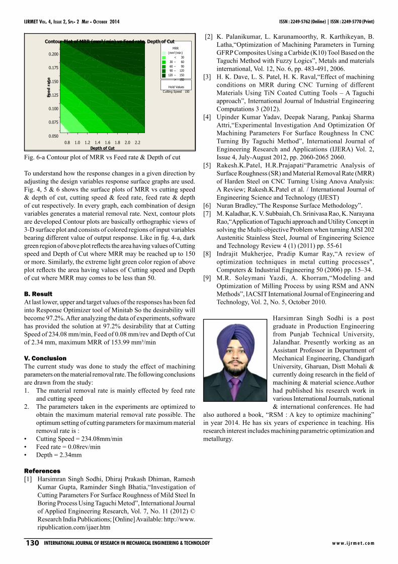
Fig. 6-a Contour plot of MRR vs Feed rate & Depth of cut
To understand how the response changes in a given direction by adjusting the design variables response surface graphs are used. Fig. 4, 5 & 6 shows the surface plots of MRR vs cutting speed & depth of cut, cutting speed & feed rate, feed rate & depth of cut respectively. In every graph, each combination of design variables generates a material removal rate. Next, contour plots are developed Contour plots are basically orthographic views of 3-D surface plot and consists of colored regions of input variables bearing different value of output response. Like in fig. 4-a, dark green region of above plot reflects the area having values of Cutting speed and Depth of Cut where MRR may be reached up to 150 or more. Similarly, the extreme light green color region of above plot reflects the area having values of Cutting speed and Depth of cut where MRR may comes to be less than 50.
B. ResultAt last lower, upper and target values of the responses has been fed into Response Optimizer tool of Minitab So the desirability will become 97.2%. After analyzing the data of experiments, software has provided the solution at 97.2% desirability that at Cutting Speed of 234.08 mm/min, Feed of 0.08 mm/rev and Depth of Cut of 2.34 mm, maximum MRR of 153.99 mm³/min
V. ConclusionThe current study was done to study the effect of machining parameters on the material removal rate. The following conclusions are drawn from the study:
The material removal rate is mainly effected by feed rate 1. and cutting speedThe parameters taken in the experiments are optimized to 2. obtain the maximum material removal rate possible. The optimum setting of cutting parameters for maximum material removal rate is :Cutting Speed = 234.08mm/min• Feed rate = 0.08rev/min• Depth = 2.34mm •
References[1] Harsimran Singh Sodhi, Dhiraj Prakash Dhiman, Ramesh
Kumar Gupta, Raminder Singh Bhatia,“Investigation of Cutting Parameters For Surface Roughness of Mild Steel In Boring Process Using Taguchi Metod”, International Journal of Applied Engineering Research, Vol. 7, No. 11 (2012) © Research India Publications; [Online] Available: http://www.ripublication.com/ijaer.htm
[2] K. Palanikumar, L. Karunamoorthy, R. Karthikeyan, B. Latha,“Optimization of Machining Parameters in Turning GFRP Composites Using a Carbide (K10) Tool Based on the Taguchi Method with Fuzzy Logics”, Metals and materials international, Vol. 12, No. 6, pp. 483-491, 2006.
[3] H. K. Dave, L. S. Patel, H. K. Raval,“Effect of machining conditions on MRR during CNC Turning of different Materials Using TiN Coated Cutting Tools – A Taguchi approach”, International Journal of Industrial Engineering Computations 3 (2012).
[4] Upinder Kumar Yadav, Deepak Narang, Pankaj Sharma Attri,“Experimental Investigation And Optimization Of Machining Parameters For Surface Roughness In CNC Turning By Taguchi Method”, International Journal of Engineering Research and Applications (IJERA) Vol. 2, Issue 4, July-August 2012, pp. 2060-2065 2060.
[5] Rakesh.K.Patel, H.R.Prajapati“Parametric Analysis of Surface Roughness (SR) and Material Removal Rate (MRR) of Harden Steel on CNC Turning Using Anova Analysis: A Review; Rakesh.K.Patel et al. / International Journal of Engineering Science and Technology (IJEST)
[6] Nuran Bradley,“The Response Surface Methodology”.[7] M. Kaladhar, K. V. Subbaiah, Ch. Srinivasa Rao, K. Narayana
Rao,“Application of Taguchi approach and Utility Concept in solving the Multi-objective Problem when turning AISI 202 Austenitic Stainless Steel, Journal of Engineering Science and Technology Review 4 (1) (2011) pp. 55-61
[8] Indrajit Mukherjee, Pradip Kumar Ray,“A review of optimization techniques in metal cutting processes", Computers & Industrial Engineering 50 (2006) pp. 15–34.
[9] M.R. Soleymani Yazdi, A. Khorram,“Modeling and Optimization of Milling Process by using RSM and ANN Methods”, IACSIT International Journal of Engineering and Technology, Vol. 2, No. 5, October 2010.
Harsimran Singh Sodhi is a post graduate in Production Engineering from Punjab Technical University, Jalandhar. Presently working as an Assistant Professor in Department of Mechanical Engineering, Chandigarh University, Gharuan, Distt Mohali & currently doing research in the field of machining & material science.Author had published his research work in various International Journals, national & international conferences. He had
also authored a book, “RSM : A key to optimize machining” in year 2014. He has six years of experience in teaching. His research interest includes machining parametric optimization and metallurgy.

IJRMET Vol. 4, IssuE 2, spl - 2 May - ocTobER 2014
w w w . i j r m e t . c o m InternatIonal Journal of research In MechanIcal engIneerIng & technology 131
ISSN : 2249-5762 (Online) | ISSN : 2249-5770 (Print)
Jasmeet Singh is a post graduate in Machine Design from Punjab Technical University, Jalandhar. Presently working as an Assistant professor in Department of Mechanical Engineering, Desh Bhagat Engineering College. He has published his research work in various International Journals, national & international conferences. He has several years of experience in teaching.
Gaurav Bansal is a graduate (B.Tech) in Mechanical Engineering from PTU, Jalandhar and is working on his post graduation (M.Tech- Machine Design). He is currently working as a lecturer in RIMT Polytechnic college in department of mechanical engineering. He has four and half years of teaching experience.