iii. improved wheelchair transportation ... rerc on wheelchair technology iii. improved wheelchair...
TRANSCRIPT
58 RERC ON WHEELCHAIR TECHNOLOGY
III. IMPROVED WHEELCHAIR TRANSPORTATION
♦ T-1 DESIGN CRITERIA FOR TRANSPORT WHEELED MOBILITY DEVICES
♦ T-2 DEVELOPMENT OF WHEELCHAIR SECUREMENT INTERFACE CONCEPTS
♦ T-3 DEVELOPMENT OF DOCKING TYPE SECUREMENT DEVICES
♦ T-4 RESEARCH COORIDINATION RELATED TO STANDARDS DEVELOPMENT FOR
WHEELCHAIR TRANSPORTATION
59FINAL REPORT: 1993-1998
TASK: T-1 DESIGN CRITERIA FOR TRANSPORT WHEELED
MOBILITY DEVICES
Rationale
Motor vehicle seats are designed to protect their
occupant in a crash. Wheelchairs designed for normal
mobility are not commonly designed to be
crashworthy. This task was intended to ultimately
provide manufacturers with design guidance for
producing wheelchair products intended to serve as
seats in motor vehicles.
Goals
1. Develop design strategies and criteria for safer
transport of Wheeled Mobility Devices (WMDs).
2. Facilitate the commercial availability of transport
WMDs manufactured in accordance with
nationally recognized industry standards.
Methods Summary
This task has relied upon a combination of
computer simulation and experimental testing.
Computer crash simulation models were developed
and validated for use in the study of factors
influencing injury risk of wheelchair occupants in a
crash. A wheelchair transportation-specific Injury
Risk Assessment method was developed and used
in the comparison of injury risk associated with
various wheelchair transportation scenarios.
Outcomes Summary
• Developed and validated a production
powerbase, dynamic model using crash
simulation software.
• Developed and validated a dynamic model of a
conventional production power wheelchair.
• Investigated the influence of rear securement
point location on frontal crash safety using
developed conventional power wheelchair and
powerbase models.
• Defined “transport wheelchair” design criteria
using computer simulation.
• Developed an Injury Risk Assessment Method
appropriate to the WMD transportation crash
environment.
• Evaluated injury risk associated with various
securement configurations through the use of the
developed Injury Risk Assessment Method.
• Evaluated the affects of shoulder belt anchor
location on wheelchair crash safety.
• Surveyed 80 various types of WMDs and
developed characteristics database appropriate for
use in WMD transportation design and research.
• Through the use of the WMD database, redefined
the ISO/SAE surrogate test wheelchair to better
represent production powered wheelchairs.
• Awarded a “Wheelchair Integrated Restraint
System” STTR grant to investigate the integration
of a total occupant restraint system.
• Demonstrated the occupant protection
advantages associated with a wheelchair
integrated restraint as compared to vehicle-
mounted restraint systems through the use
computer simulation and the developed Injury
Risk Assessment method.
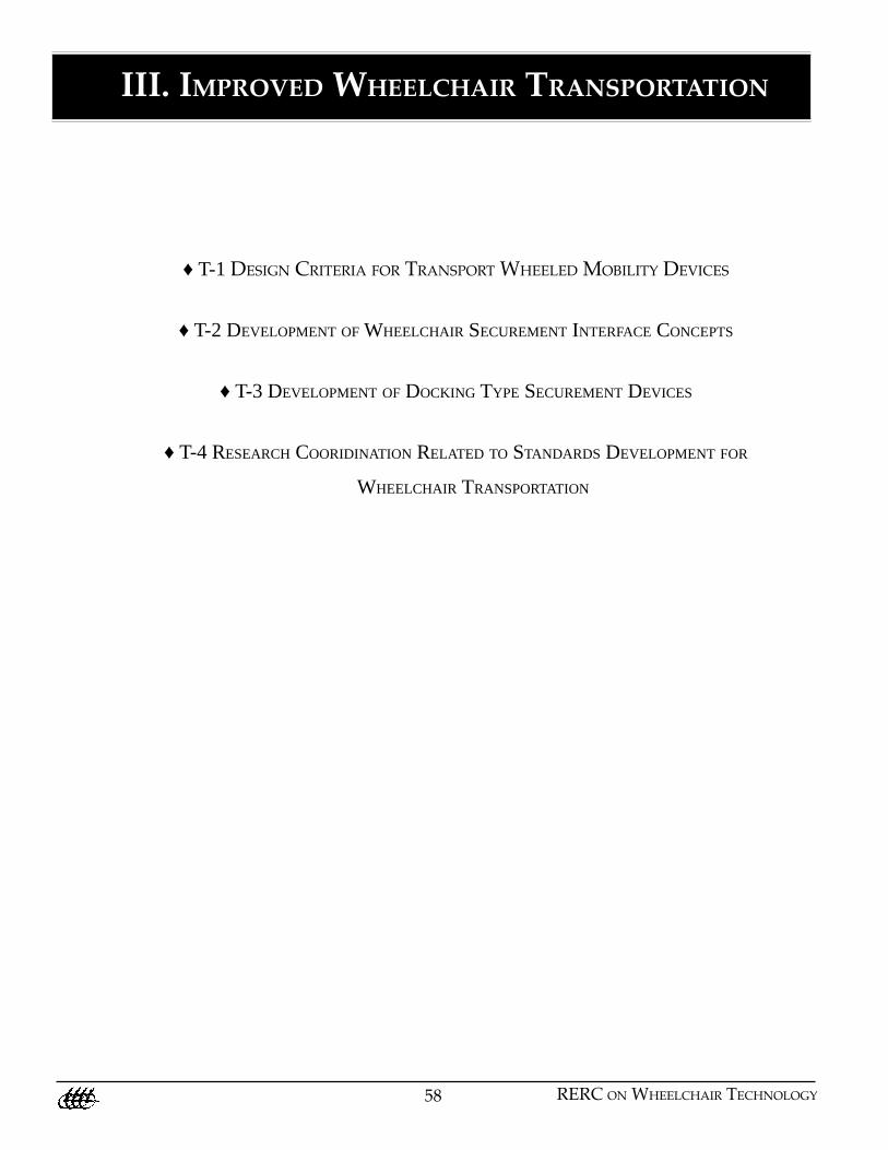
• Developed a psuedo-dynamic test to evaluate the
crashworthiness of commonly used caster
assemblies.
• Evaluated the crashworthiness of common
wheelchair caster assemblies using developed test
methods.
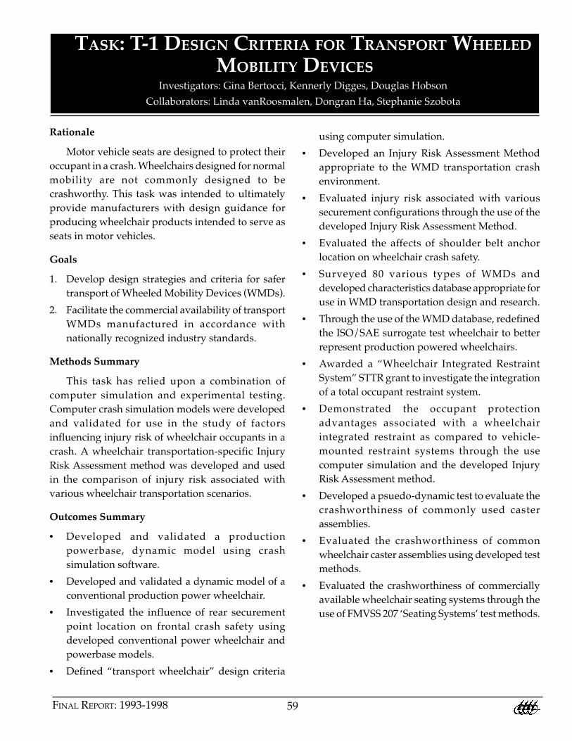
• Evaluated the crashworthiness of commercially
available wheelchair seating systems through the
use of FMVSS 207 ‘Seating Systems’ test methods.
Investigators: Gina Bertocci, Kennerly Digges, Douglas Hobson
Collaborators: Linda vanRoosmalen, Dongran Ha, Stephanie Szobota
60 RERC ON WHEELCHAIR TECHNOLOGY
Figure 42 – Dynamic Drop Testing of Caster Assemblies
AppliedForce
DropWghts.
CasterTestFixture
Recommended Future Research
Future research efforts will focus on the
crashworthiness of wheelchairs and their components
in rear and side impact scenarios. Additional efforts
related to the study of frontal impact will concentrate
on the development and validation of a computer
model to predict occupant submarining when seated
in a wheelchair. Various seating characteristics will
be evaluated to determine their influence on injury
risk and in particular submarining.
Figure 43 – FMVSS 207 Seating System Testing of Wheelchair Seats
Publications
Bertocci GE, Digges K, Hobson D, Development of
Transportable Wheelchair Design Criteria Using Computer
Crash Simulation. IEEE Transactions on Rehabilitation
Engineering, Vol 4, No 3, Sept. 1996: 171-181.
Bertocci GE, Digges K, Hobson DA, Shoulder Belt Anchor
Location Influences on Wheelchair Occupant Crash
Protection. Journal of Rehab Research and Devel, Vol 33,
No 3, July 1996:279-289.
Bertocci GE, Karg, P, Hobson D, Wheeled Mobility Device
Database for Transportation Safety Research and
Standards. Assistive Technology, Vol 9.2, 1997.
61FINAL REPORT: 1993-1998
Bertocci GE, Esteireiro J, Cooper RA, Young TM, Thomas
C, Testing and Evaluation of Wheelchair Caster Assemblies
Subjected to Dynamic Crash Loading. To appear in Journal
of Rehab Research and Development, Vol 36, No. 1, January
1999.
Bertocci GE, Digges, K, Hobson DA, Computer Simulation
and Sled Test Validation of a Powerbase Wheelchair and
Occupant Subjected to Frontal Crash Conditions. To appear
in IEEE Trans Rehab Engr, Vol 7, No 2, June 1999.
Bertocci GE, Digges, K, Hobson DA, Development of a
Wheelchair Occupant Injury Risk Assessment Method and
Its Application in the Investigation of Wheelchair
Securement Point Influence on Frontal Crash Safety.
Conditionally accepted in IEEE Transactions on
Rehabilitation Engineering, Nov. 1997.
Digges K, Bertocci GE, Application of the ATB Program to
Wheelchair Transportation. Technical Report #3,
University of Pittsburgh RERC, Nov 1995.
Bertocci GE, Hobson D, The Affects of Securement Point
Location on Wheelchair Crash Response. Proceedings of
the RESNA ‘96 Annual Conference RESNA Press,
Washington DC, June 1996.
Bertocci GE, The Affects of Shoulder Belt Anchor Position
on Wheelchair Transportation Safety. Proceedings of the
RESNA ‘95 Annual Conference. RESNA Press, Washington,
DC, 1995: 311-313.
Bertocci GE, Karg P, Hobson D, Wheelchair Classification
System and Database Report, Technical Report #6,
University of Pittsburgh RERC on Wheelchair Mobility,
Pittsburgh, PA 1996.
Bertocci GE, Digges K, Hobson D, The Affects of
Wheelchair Securement Point Location on Occupant Injury
Risk. Proceedings of the RESNA ’97 Annual Conference,
RESNA Press, Washington DC, Jan 1997. Recipient of 1997
RESNA/Whitaker Scientific Paper Competition Award.
Bertocci GE, Karg PE, Survey of Wheeled Mobility Device
Transport Access Characteristics. Proceedings of the
RESNA ’97 Annual Conference, RESNA Press, Washington
DC, Jan 1997.
Bertocci GE, Ph.D. Dissertation: The Influence of
Securement Point and Occupant Restraint Anchor Location
on Wheelchair Frontal Crash Safety, July 1997.
VanRoosmalen, L, Ha, D, Bertocci, G, Karg, P, Szobota, S,
An Evaluation of Wheelchair Seating System
Crashworthiness Using Federal Motor Vehicle Safety
Standard (FMVSS) 207 Testing, Submitted to RESNA ’99
Conf, Dec, 1998.
Bertocci GE, Esteireiro J, Cooper RA, Young TM, Thomas
C, Testing and Evaluation of Wheelchair Caster Assemblies
Subjected to Dynamic Crash Loading. Proceedings of RESNA
‘98 Annual Conference, June 1998.
Karg P, Bertocci GE, Hobson DA, Status of Universal
Interface Design Standard for Mobility Device Docking on
Vehicles. Proceedings of the RESNA ‘98 Annual Conference,
June 1998.
Van Roosmalen L, Bertocci GE, Karg PE, Young TM, Belt
Fit Evaluation of Fixed Vehicle Mounted Shoulder Restraint
Anchor Across Mixed Occupant Populations. Proceedings
of the RESNA ‘98 Annual Conference, June 1998.
Bertocci GE, Development of Transportable Wheelchair
Design Criteria Using Computer Crash Simulation.
Proceedings of 1998 Articulated Total Body Modeling
Conference, April 1998.
62 RERC ON WHEELCHAIR TECHNOLOGY
TASK: T-2 DEVELOPMENT OF WHEELCHAIR SECUREMENT
INTERFACE CONCEPTS
Investigators: Gina Bertocci, Jules Legal, Douglas Hobson and Patricia Karg
Rationale
Wheelchairs, their securement devices, occupant
restraints and transport vehicles all must function as
a system, if individuals are to safely and
independently use both public and personal vehicles
while remaining seated in their wheelchairs.
Currently, securement systems for wheelchairs are
often inadequately applied, are time consuming to
use, and require the involvement of a vehicle operator
or an attendant. A universal solution is needed that
provides independent, quick, and safe securement.
Improving accessibility and safety relies upon
standardized methods being developed and adopted
for interconnecting the respective technologies. The
successful development of new docking-type
securement devices, that eliminate several of the
disadvantages of commonly used belt-type devices,
depends upon standardized ways of interconnecting
the wheelchair with vehicle-mounted securement
hardware. The adoption and promulgation of a
universal interface device (UID) standard for docking
devices can ultimately mean that a person can access
and have their wheelchair secured in any transport
vehicle, in a manner offering equivalent safety to
other riders seated on the vehicle.
Goals
The goal of this project was to facilitate the
adoption of a universal interface device standard
developed by a trans-industry effort. The approach
chosen to reach this goal was as follows:
1. research, develop and evaluate design
specifications for universal interface hardware
designs that meet constituency-defined needs;
2. conceptualize universal interface device concepts
that will foster compatibility between present and
future technologies; and
3. foster acceptance and inclusion of concepts and
design specifications in national and international
standards development.
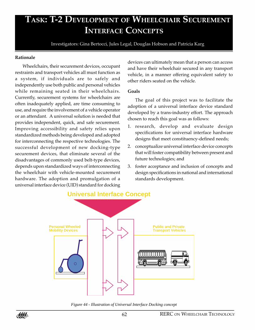
Figure 44 - Illustration of Universal Interface Docking concept
Personal WheeledMobility Devices
Public and PrivateTransport Vehicles
Universal Interface Concept
63FINAL REPORT: 1993-1998
Standardization of the geometry and location of
the docking hardware on wheeled mobility devices
will allow industry to design and produce vehicle-
mounted docking securement devices that are
universally compatible.
Methods Summary
The first step in the process was to characterize
wheelchair frames and determine the feasibility of
adding a common universal attachment. A database
of wheelchair frames was developed in this process.
This work helped to identify the optimal location for
placement of the hardware, as well as necessary clear
zones surrounding the hardware. Another initial step
was to gather information on the state of the
technology in transport vehicles and securement
design. In addition, consensus among the involved
constituents on the need for a UID had to be
established. Reaching agreement on a UID for
docking devices between diverse interests such as
wheelchair users, wheelchair manufacturers, tiedown
manufacturers, vehicle manufacturers and
transporters is a challenging undertaking. Focus
group meetings, one involving wheelchair users and
the other involving industry, were held to this end.
Once it was established that there was a need for a
UID standard, the two groups worked toward
defining and prioritizing the design criteria.
Establishment and priority ranking of the criteria
and definition of the clear zones was only the first
step. To be adopted universally and eventually
promulgated through national and international
industry standards, feasibility of the approach had
to be demonstrated. Therefore, a series of potential
interface hardware designs meeting the criteria were
developed and tested. To ensure that the designs met
the defined criteria, the RERC, as in other tasks, used
the Quality Function Deployment (QFD) design
proces. The QFD is a design tool that involves a
multidisciplinary design approach. It is a process for
translating customer requirements into appropriate
technical requirements at each stage of the product
development process. This process allows for
proactive quality control and focuses on planning and
problem prevention, rather than problem solving
down the road. The process is accomplished through
a series of matrices and charts that deploy customer
requirements and related technical requirements
through the product development phases. The first
step of the QFD process involves developing the
matrix known as the “House of Quality”, which is a
basic design tool. The defined and ranked design
criteria and identified clear zones were used as inputs
to the QFD design matrix.
Several conceptual hardware configurations
were designed and fitted to test wheelchairs (Figure
44a&b). The initial concepts were evaluated through
feedback from users and industry, strength testing
and compatibility testing with production
wheelchairs. The evaluations and feedback led to a
final design that was further evaluated. The latter
design was incorporated into a draft standard and
submitted to an independent standard development
group (ANSI/RESNA) for further development and
creation of a standard. Details of the outcomes of
this process are presented below.
Outcomes Summary
Design and Development
The concept of the universal interface was first
presented in the 1995 RESNA Proceedings {Hobson,
1995}. Initial development activities were reported in
the 1997 RESNA Proceedings {Karg, 1997}. The initial
activities focused on an investigation of the array of
wheelchair frames in an effort to categorize them and
determine commonalties. A survey data form of 45
data points was developed to record relevant
wheelchair characteristics, and a database was
constructed to maintain and organize the information
{Bertocci, 1996; Bertocci, 1997}. This survey provided
important information such as the location of the
center of gravity and the nature of the existing frame
configurations with respect to the ease of adding a
common universal attachment design for the purpose
of docking securement on motor vehicles. This was
used to identify the optimal location for placement
of the hardware, as well as the necessary clear zones.
Additional efforts included gathering information
on flip-up bus seats, current securement
configurations and wheelchair compartment designs
on vehicles. Current docking devices were also
64 RERC ON WHEELCHAIR TECHNOLOGY
obtained for evaluation. Visitations to leading
securement companies were made, providing insight
into the current state of the technology.
The next step was to organize and host industry
meetings and consumer focus groups to identify the
desire and need for a universal design standard, and
to identify design specifications. Two industry
meetings have been held that included wheelchair
manufacturers, securement manufacturers, vehicle
manufacturers, and transporters. A focus group
comprising manual and power wheelchair users that
use public and/or private transportation was held
in the time between the two industry meetings.
There was overwhelming agreement on the need
for a universal interface for docking devices and that
a design standard should be pursued. To that end,
the two groups then generated lists of design criteria
for the universal interface; a list of 19 criteria resulted
from the two groups. The eight criteria listed below
were included in the top 6 ranked criteria of the
consumer group and/or the industry group. The first
two bullets were ranked first and second priority by
both groups independently, and the third and fourth
appeared on both lists. The remaining four appeared
on only one of the ranked lists as indicated by either
an “I” (industry) or a “C” (consumer) following the
criterion. These criteria and their ranking provided a
target for the ensuing research effort. These results
have been disseminated to two standards
development groups.
The partial listing of the design criteria for the
universal interface, as referenced above, is as follows.
• Meet all applicable safety standards (I, C)
• Promote independent securement (I, C)
• Maintain original function of wheelchair (e.g.,
folding, feel, maneuverability) (I, C)
• Accommodate all wheelchair types and sizes that
are used as motor vehicle seats (I, C)
• Compatible with all vehicle types that transport
passengers seated in wheelchairs (driver docking
and fold-down seats accommodated) (C)
• Promote quick securement time (less than 1
minute from being positioned at the securement
station to securement) (C)
• Does not preclude use of existing tie-down and
occupant restraint systems (I)
• Allow retrofit to existing wheelchairs (I)
The design criteria were used to implement the
Quality Function Deployment (QFD) design process.
This method was used to assure the needs and desires
of all project stakeholders have been considered and
are effectively incorporated into the design of the
hardware. Finally, several hardware designs were
developed and some fabricated for consideration and
evaluation. Clear zone requirements with respect to
the wheelchair to allow access to interface hardware
were also established. Industry and consumer
representatives indicated they would like the
feasibility of the designs evaluated before the
standard was created and subsequent work was
performed to this end. The evaluation of the proposed
hardware designs and status of these efforts were
reported at the 1998 RESNA Conference {Karg, 1998}.
The UID standard will provide the basis by which
all involved industries can design and produce
compatible wheelchair securement products. Design
of the docking devices will be limited only in that the
wheelchair hardware (i.e., the universal interface)
geometry, location in space, and surrounding
clearance will be defined. The industry meetings
centered around the debate of two configurations of
a UID located on the lower rear portion of the
wheelchair. One configuration, that was favored after
the second industry meeting, is two vertically
oriented structures (Figure 44a), aligned side by side
{Karg, 1997}. However, the discussions in the third
meeting (June 1997) tended to return to the appealing
approach of having a horizontal bar across the rear,
similar to the grab bars offered on several scooters
(Figure 44b). Evaluations of these two configurations
revealed several pros and cons of each (detailed
below). The horizontal bar proved better for ease of
retrofit to existing wheelchairs however, did not
provide a reaction point to prevent rear or end
wheelchair rotation during a crash. Thus, two
horizontal bars may be necessary. The vertical
configuration would allow for the needed stability,
however appeared to be more difficult to retrofit and
integrate into existing wheelchair designs.
65FINAL REPORT: 1993-1998
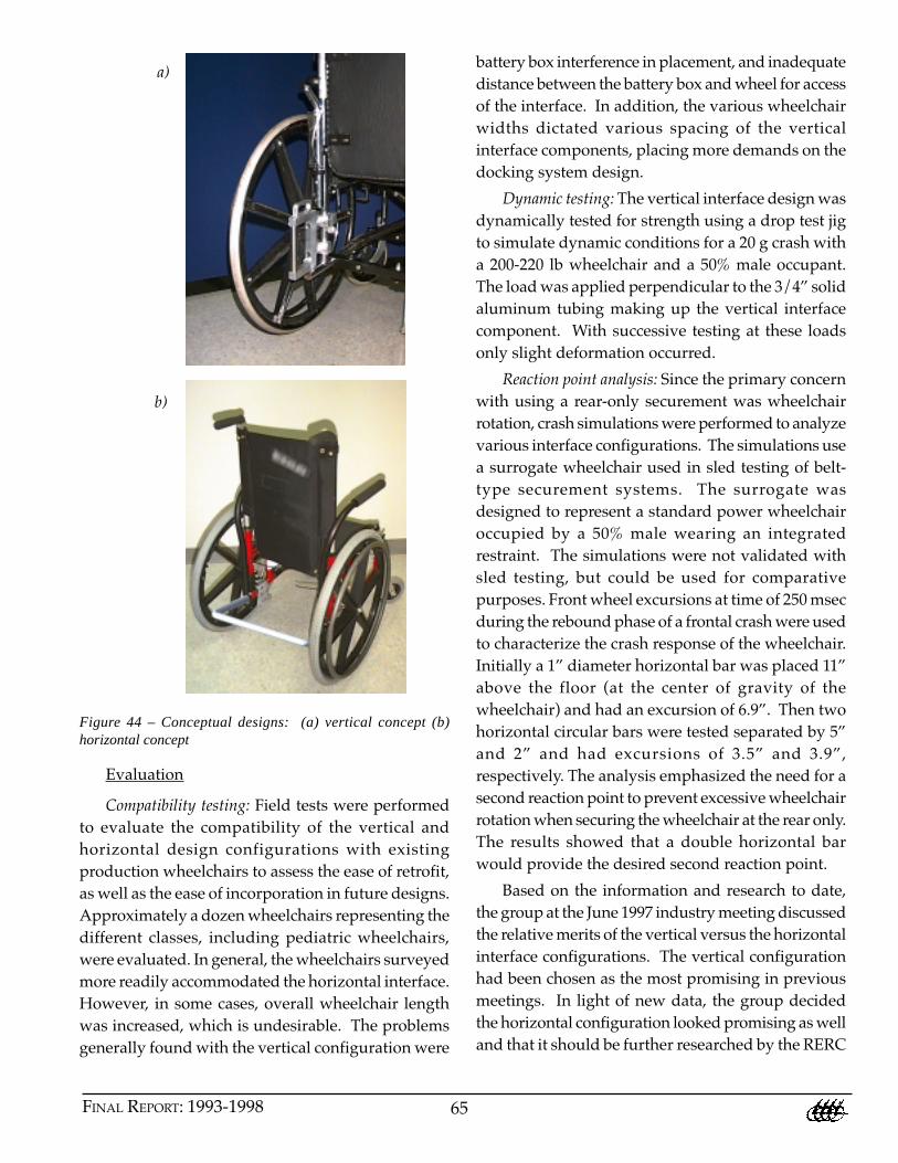
Figure 44 – Conceptual designs: (a) vertical concept (b)horizontal concept
Evaluation
Compatibility testing: Field tests were performed
to evaluate the compatibility of the vertical and
horizontal design configurations with existing
production wheelchairs to assess the ease of retrofit,
as well as the ease of incorporation in future designs.
Approximately a dozen wheelchairs representing the
different classes, including pediatric wheelchairs,
were evaluated. In general, the wheelchairs surveyed
more readily accommodated the horizontal interface.
However, in some cases, overall wheelchair length
was increased, which is undesirable. The problems
generally found with the vertical configuration were
battery box interference in placement, and inadequate
distance between the battery box and wheel for access
of the interface. In addition, the various wheelchair
widths dictated various spacing of the vertical
interface components, placing more demands on the
docking system design.
Dynamic testing: The vertical interface design was
dynamically tested for strength using a drop test jig
to simulate dynamic conditions for a 20 g crash with
a 200-220 lb wheelchair and a 50% male occupant.
The load was applied perpendicular to the 3/4” solid
aluminum tubing making up the vertical interface
component. With successive testing at these loads
only slight deformation occurred.
Reaction point analysis: Since the primary concern
with using a rear-only securement was wheelchair
rotation, crash simulations were performed to analyze
various interface configurations. The simulations use
a surrogate wheelchair used in sled testing of belt-
type securement systems. The surrogate was
designed to represent a standard power wheelchair
occupied by a 50% male wearing an integrated
restraint. The simulations were not validated with
sled testing, but could be used for comparative
purposes. Front wheel excursions at time of 250 msec
during the rebound phase of a frontal crash were used
to characterize the crash response of the wheelchair.
Initially a 1” diameter horizontal bar was placed 11”
above the floor (at the center of gravity of the
wheelchair) and had an excursion of 6.9”. Then two
horizontal circular bars were tested separated by 5”
and 2” and had excursions of 3.5” and 3.9”,
respectively. The analysis emphasized the need for a
second reaction point to prevent excessive wheelchair
rotation when securing the wheelchair at the rear only.
The results showed that a double horizontal bar
would provide the desired second reaction point.
Based on the information and research to date,
the group at the June 1997 industry meeting discussed
the relative merits of the vertical versus the horizontal
interface configurations. The vertical configuration
had been chosen as the most promising in previous
meetings. In light of new data, the group decided
the horizontal configuration looked promising as well
and that it should be further researched by the RERC
a)
b)

66 RERC ON WHEELCHAIR TECHNOLOGY
team, especially with respect to stability and
wheelchair rotation.
Hybrid interface design and evaluation
The hybrid interface (Figures 45 and 46) appears
to provide the advantages of both the horizontal and
vertical design concepts, along with providing the
critical anti-rotational reaction points. This approach
has an advantage over the double horizontal bar
approach by reducing the level of complexity of
docking system-to-interface engagement.
Additionally, the hybrid interface promotes docking
system centering on the wheelchair. The proposed
dimensions are intended to be wheelchair compatible,
and are based upon the previous surveys and data
analysis across varying wheelchair types.
Figure 46 - Hybrid UID concept, example of integration into a(a) powered wheelchair and (b) a scooter
Figure 45 - Hybrid UID concept and design specification
We conducted preliminary simulations using a
2-D Working Model analysis. The model was not
validated, but was used to obtain a general evaluation
of the crash dynamics and response of the wheelchair
with the hybrid interface. The wheelchair exhibited
a controlled response in these simulations. The next
step was to perform static testing on the hybrid
design. The testing showed that the UID maintained
up to a 10,400-lb load. When failure occurred, it was
at the point where the UID interfaced with the test
jig, which in this case was a press fit into the UID
tubing, resulting in an area of stress concentration.
The final evaluation was a dynamic test that used the
hybrid design to interface an SAE surrogate
wheelchair with a docking system that had been
designed, in part, to prove the feasibility that a
docking system could be designed that would
successfully mate with the hybrid interface design.
The sled test was performed according to the SAE
J2249 specification [SAE, 1996]. The test met J2249
requirements for wheelchair and occupant response
and proved the feasibility of the hybrid UID concept.
Recommended Future Developments
The final step as the RERC funding period came
to a close was to formalize the standard development
process with an independent standard agency. In
Spring1998, a formal request and draft standard was
submitted to ANSI/RESNA Technical Guidelines
Committee to initiate a new work item on the UID
Standard. The new work item has been approved
and work will begin in Spring 1999. The draft
standard must now continue through the standard
development process in the hands of the ANSI/
RESNA working group for the transport wheelchair
(SOWHAT).
a)
b)

67FINAL REPORT: 1993-1998
Publications
Bertocci GE, Karg PE, Hobson DA, Wheeled Mobility
Device Classification System and Database, Technical
Report #6, University of Pittsburgh RERC on Wheelchair
Mobility, Pittsburgh, PA 1996.
Bertocci GE and Karg PE. Wheeled mobility device
database for transportation safety research and standards.
Assistive Technology 1997, 9.2: 102-15.
Hobson DA, Securement of Wheelchairs in Motor Vehicles.
Proceedings of the RESNA ‘95 Annual Conference, RESNA
Press, Washington DC, 1995.
Karg PE, Bertocci GE, Hobson DA. Status of universal
interface design standard for mobility device docking on
vehicles. Proceedings of the RESNA ’98 Annual
Conference, RESNA Press, Washington, DC, 1998.
Karg PE, Bertocci GE, Hobson DA. Universal interface
hardware design standard for mobility device transport
docking systems. Proceedings of the RESNA ’97 Annual
Conference, RESNA Press, Washington DC, 1997: 29-31.
References
Brown PG, QFD: Echoing the voice of the customer, AT&T
Technical Journal, March/April, 1991, pp. 18-32.
Hauser JR, Clausing D The house of quality, The Product
Development Challenge, Harvard Business Review Book,
eds. Kim B. Clark and Steven C. Wheelwright, pp. 299-
315, 1995.
SAE. SAE J2249, Wheelchair tie-downs and occupant
restraints (WTORS) for use in motor vehicles. Society of
Automotive Engineers, Warrendale, PA, 1996.
68 RERC ON WHEELCHAIR TECHNOLOGY
TASK: T-3 DEVELOPMENT OF DOCKING TYPE
SECUREMENT DEVICES
Investigators: Douglas Hobson, Gina Bertocci, Patricia Karg and Mark McCartneyStudents: Linda van Roosmalen, Jonathan EvansCollaborator: Jules Legal
Rationale
The industry standard today for wheelchair
securement in all types of vehicles is the four point
strap-type tiedown device. Although this device
performs adequately under crash conditions when
properly installed and used, it has several major
shortcomings. The main one is that it does not permit
wheelchair users the independent use of transit
vehicles. All belt-type tiedown devices require the
vehicle operator or an attendant to fasten and
unfasten both the wheelchair securement and the
occupant restraint. A self-docking wheelchair
securement device, combined with an “on-
board”(integrated) occupant restraint, offers the
potential to resolve many of the inherent
shortcomings of the existing devices.
Review of the transit accident statistics and crash
severities for large mass transit vehicles {Hobson, et
al. 1997} strongly suggests that the chances of a transit
vehicle occupant experiencing a high “g” crash event
are very small. Therefore, one can take the position,
with a relatively low degree of risk, that a wheelchair
user seated forward–facing in a transit wheelchair
compartment will only experience those “g” loads
associated with normal driving, i.e., maximum
braking, acceleration and rapid turning. Actual
measurements have shown these “g” loads to be less
than 0.65g [Bertocci, et al. 1997]. If this could be shown
to be feasible, it could provide an immediate solution
to improved securement, since the adoption of any
approach using a universal interface drive (UID) is
by necessity a long-term solution.
In order to demonstrate the feasibility of the
proposed universal interface standard detailed in task
T2 [Karg et al. 1997], it was essential to develop and
test actual docking-type securement devices that
could meet the standard. This was done with the
expectation that successful designs would eventually
lead to commercial products.
Another solution for wheelchair containment in
large vehicles is to simply place the occupied
wheelchair rearward facing in a designated station
in the vehicle. The stability of the wheelchair is then
dependent on its brakes, a hand-hold for the
occupant, a padded bulkhead behind the wheelchair
and a vertical stanchion, which prevents the
wheelchair from rotating into the aisle. This study
also looked at the importance of the floor material
selection in optimizing the effectiveness of the brakes
to prevent instability (sliding) towards the rear of the
vehicle when the transit vehicle ascends hills.
Therefore, the multiple approaches taken in task
T-3 were to first develop and test docking devices that
meet two levels of crash severity: a) 30mph, 20g,
frontal crash termed a high “g” crash; and b) loads
associated with normal driving in large vehicles,
termed low “g”. Finally, to explore stability risks
associated with rear-facing compartments as a means
of wheelchair containment, now commonly used in
many European and several Canadian public transit
vehicles.
Goals
1. To design, develop, and demonstrate a high “g”
docking-type securement devices for potential
use in both private and public transport vehicles.
2. To design, develop, and demonstrate a low “g”
docking-type securement devices for potential
use in large public transit vehicles.
3. To explore the sliding stability risks of rear-facing
containment compartments used in public transit
vehicles.
Methods/Results Summary
1) High “g” - crash conditions
The Pitt RERC team took several steps to obtain
the design criteria for the high “g” docking devices.
69FINAL REPORT: 1993-1998
First, the Quality Function Deployment (QFD) tool
was used in two focus group sessions to
systematically seek and prioritize the views of
researchers, transit operators and wheelchair users
of transit vehicles. This information combined with
the ADA requirements for public transit vehicles
established the design goals for the device design.
These criteria were used to develop a conceptual
paper design.
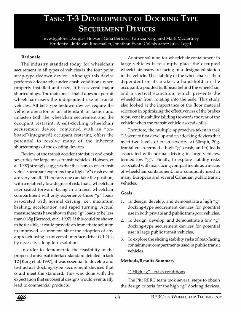
The next step was to establish the crash loads that
the device components would need to withstand
during a 30mph, 20g, frontal crash event. This was
done using a computer simulation model as shown
in Figure 47.
prototype docking system unit was then installed in
the mockup test station. Wheelchair users were
invited to evaluate maneuverability and ease of
docking.
Based on the results of the above testing, plans
have been made to proceed with a Phase II, NIH-
STTR proposal in an effort to further refine and
commercialize the docking system.
2) Low “g” Docking Device
In summary, the focus of this aspect of the task
was to develop a user-activated wheelchair
containment device for use in large transit vehicles
that would readily secure any wheelchair entering
the vehicle. Again, the QFD process and focus groups
were used to arrive at the design criteria. Two
generations of prototype devices were constructed
and tested in the laboratory and with wheelchair
users. A goal of 1 g was established as the minimum
load that the device must withstand when securing a
variety of different wheelchairs, both manual and
powered. This would provide a margin of
approximately 0.35g above the maximum loads
actually measured (0.65g) during normal driving
maneuvers. Static pull tests were used to simulate
the securement loading by an occupied wheelchair
under maximum normal driving conditions. The
static pull tests were applied in the frontal direction
until the wheelchair released or substantially moved
within the containment device (Figures 49-51).
Figure 47 - Frontal Crash Simulation; Wheelchair Secured UsingProposed Universal Interface Hardware
A partnership was formed with Kinedyne
Corporation, a commercial manufacturer of strap–
type securement devices. This partnership was
successful in securing an $100,000 NIH-STTR grant
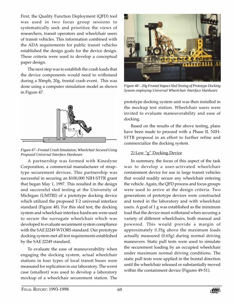
that began May 1, 1997. This resulted in the design
and successful sled testing at the University of
Michigan (UMTRI) of a prototype docking device
which utilized the proposed T-2 universal interface
standard (Figure 48). For this sled test, the docking
system and wheelchair interface hardware were used
to secure the surrogate wheelchair which was
developed to evaluate securement system compliance
with the SAE J2249 WTORS standard. Our prototype
docking system met all test requirements established
by the SAE J2249 standard.
Figure 48 – 20g Frontal Impact Sled Testing of Prototype DockingSystem employing Universal Wheelchair Interface Hardware
To evaluate the ease of maneuverability when
engaging the docking system, actual wheelchair
stations in four types of local transit buses were
measured for replication in our laboratory. The worst
case (smallest) was used to develop a laboratory
mockup of a wheelchair securement station. The

70 RERC ON WHEELCHAIR TECHNOLOGY
Figure 49 - Close-up of the low “g” Docking System Prototype
wheelchair creating two modes of restraint – friction
and mechanical interlocking. Both air pressures (plate
drive, cylinders and bellows) are adjustable so
possible wheelchair damage to wheelchairs can be
minimized. The prototype securement device, if
successful, would ultimately be designed to fit within
the geometry of a standard bus seat.
Figure 50 – Low “g” Docking System Securing PowerWheelchair
Docking Device Operation
The prototype consists of two horizontally
adjustable plates that have inflatable bellows built
into the plates. After backing the wheelchair into the
securement device, the user flips an accessible switch,
which activates two pneumatic cylinders that move
the plates towards the wheelchair chair. The plate
drive mechanism is self-centering so it can
compensate for misalignment of the wheelchair in the
docking station. Once the plates contact the
wheelchair, the bellows inflate into the cavities of the
Figure 51 – Pull testing set up of the low “g” prototypesecurement device
Test Procedure
Eight manual and powered wheelchairs were
obtained for testing. The geometry and weight of
the chairs were recorded. A person that approximated
a 50th percentile male mass distribution was used as
the occupant. Several measurements were taken on
each wheelchair including the position of the rear
wheels and into which cavities the bellows inflated.
The wheelchair was then placed in the docking
system with the brakes engaged. The setup includes
a platform to which the docking system is fixed. A
winch with a 4000 lbs. capacity was fixed to the base
of the platform in order to apply a horizontal static
load at the combined height of the wheelchair and
users center of gravities. The docking system was
then engaged. Plate pressure, bellows pressure,
which bellows contacted the wheelchair and the
nature of the contact (friction or mechanical
interlocking), was recorded. The test involved
applying a static load to the wheelchair in 40-pound
increments, measuring the horizontal displacement
of the wheelchair after each increment.
71FINAL REPORT: 1993-1998
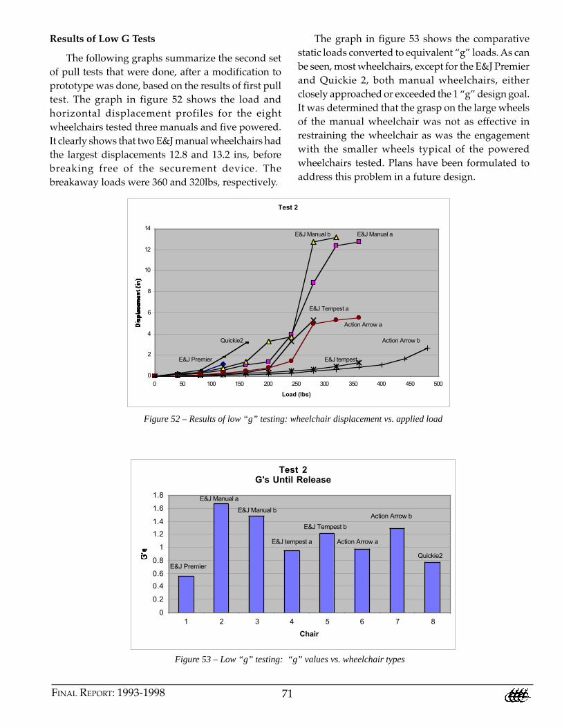
Results of Low G Tests
The following graphs summarize the second set
of pull tests that were done, after a modification to
prototype was done, based on the results of first pull
test. The graph in figure 52 shows the load and
horizontal displacement profiles for the eight
wheelchairs tested three manuals and five powered.
It clearly shows that two E&J manual wheelchairs had
the largest displacements 12.8 and 13.2 ins, before
breaking free of the securement device. The
breakaway loads were 360 and 320lbs, respectively.
Figure 52 – Results of low “g” testing: wheelchair displacement vs. applied load
Figure 53 – Low “g” testing: “g” values vs. wheelchair types
The graph in figure 53 shows the comparative
static loads converted to equivalent “g” loads. As can
be seen, most wheelchairs, except for the E&J Premier
and Quickie 2, both manual wheelchairs, either
closely approached or exceeded the 1 “g” design goal.
It was determined that the grasp on the large wheels
of the manual wheelchair was not as effective in
restraining the wheelchair as was the engagement
with the smaller wheels typical of the powered
wheelchairs tested. Plans have been formulated to
address this problem in a future design.
Test 2
0
2
4
6
8
10
12
14
0 50 100 150 200 250 300 350 400 450 500
Load (lbs)
E&J Premier
Quickie2
E&J Tempest a
E&J Manual b E&J Manual a
E&J tempest
Action Arrow a
Action Arrow b
Test 2G's Until Release
0
0.2
0.4
0.6
0.8
1
1.2
1.4
1.6
1.8
1 2 3 4 5 6 7 8
Chair
E&J Premier
E&J Manual a
E&J Manual b
E&J tempest a
E&J Tempest b
Action Arrow a
Action Arrow b
Quickie2
72 RERC ON WHEELCHAIR TECHNOLOGY
3) Sliding Stability Tests of Rearward Racing
Wheelchairs
Background
Wheelchairs and their occupants transported on
large vehicles in European countries are often secured
using a compartment approach. Similar methods are
currently under consideration in Canada for use in
large transit vehicles traveling at low speeds and
having low incidence of frontal crash [Shaw, 1997].
Compartmentalization consists of a rear facing
wheelchair positioned in front of a padded bulkhead,
which is used as back restraint. A vertical stanchion
is aligned with the aisle to prevent rotation of the
wheelchair into the aisle and to provide a hand-hold
for occupants. Under such conditions, the ability of
the wheelchair to stay in place without slipping
during normal driving maneuvers is critical to the
safety and security of the occupant and other
passengers.
In the US, wheelchair stations on public transit
vehicles are typically equipped with four tiedown
straps to secure the wheelchair. However, due to
inconveniences, it is not uncommon to find a high
level of disuse of these wheelchair tiedown systems.
Under these conditions, wheelchair slippage also
becomes a concern during normal driving. Since
wheelchair slippage is dependent upon the friction
between the wheelchair tires and vehicle flooring, it
is of interest to evaluate the effects of various flooring
surfaces on wheelchair slippage. (Note: The authors
do not advocate traveling without wheelchair
securement and recommend the use of four tiedowns
and occupant restraints under all conditions.)
Goal
The goal of this study was to evaluate the
influence of floor surface materials on wheelchair
slippage under conditions simulating normal driving
maneuvers and typical road terrain.
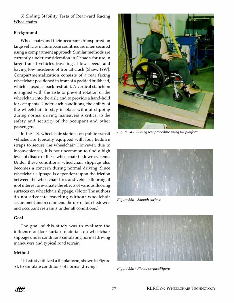
Method
This study utilized a tilt platform, shown in Figure
54, to simulate conditions of normal driving.
Figure 54 - Sliding test procedure using tilt platform
Figure 55a - Smooth surface
Figure 55b - Fluted surfaceFigure
73FINAL REPORT: 1993-1998
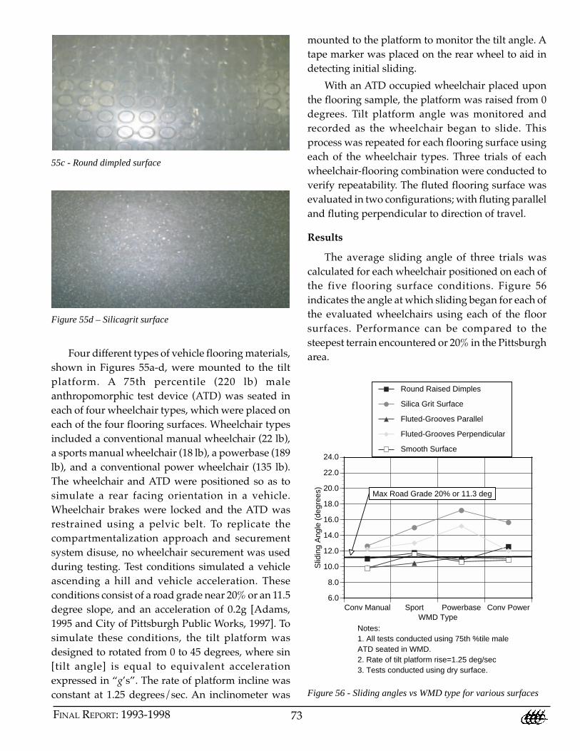
55c - Round dimpled surface
mounted to the platform to monitor the tilt angle. A
tape marker was placed on the rear wheel to aid in
detecting initial sliding.
With an ATD occupied wheelchair placed upon
the flooring sample, the platform was raised from 0
degrees. Tilt platform angle was monitored and
recorded as the wheelchair began to slide. This
process was repeated for each flooring surface using
each of the wheelchair types. Three trials of each
wheelchair-flooring combination were conducted to
verify repeatability. The fluted flooring surface was
evaluated in two configurations; with fluting parallel
and fluting perpendicular to direction of travel.
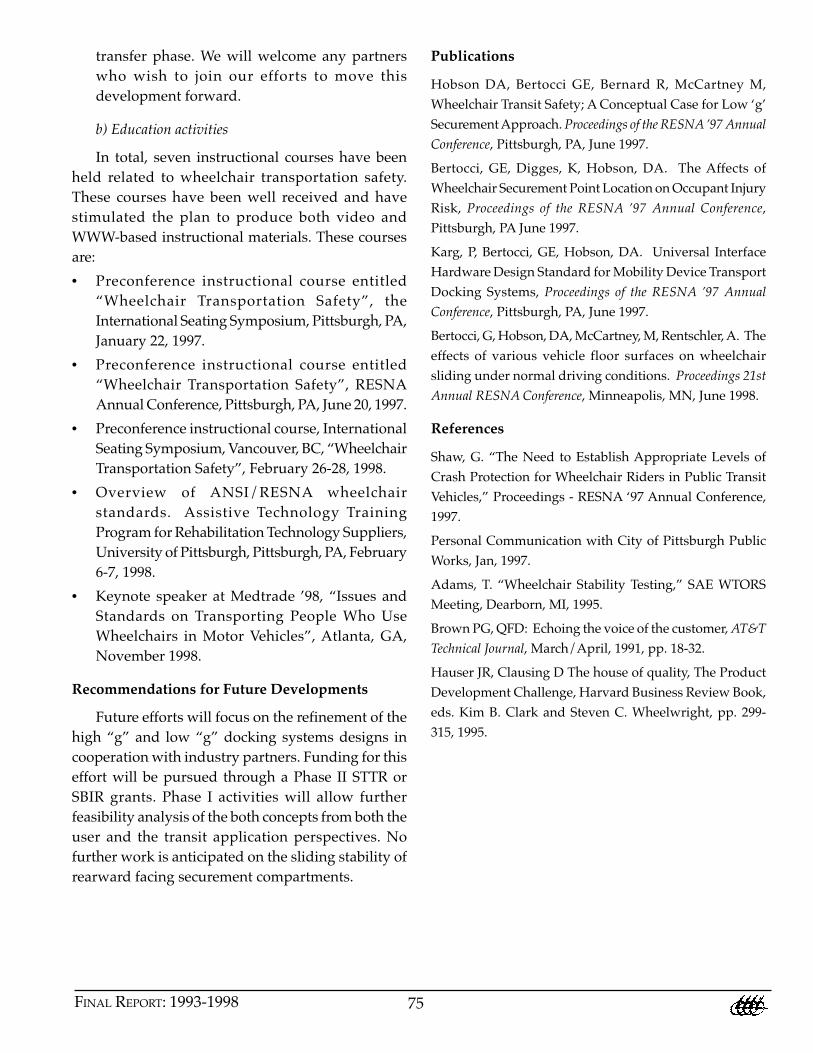
Results
The average sliding angle of three trials was
calculated for each wheelchair positioned on each of
the five flooring surface conditions. Figure 56
indicates the angle at which sliding began for each of
the evaluated wheelchairs using each of the floor
surfaces. Performance can be compared to the
steepest terrain encountered or 20% in the Pittsburgh
area.
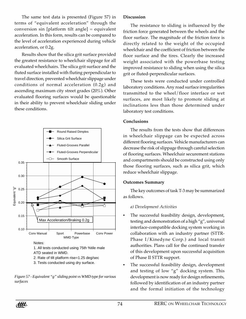
Figure 55d – Silicagrit surface
Four different types of vehicle flooring materials,
shown in Figures 55a-d, were mounted to the tilt
platform. A 75th percentile (220 lb) male
anthropomorphic test device (ATD) was seated in
each of four wheelchair types, which were placed on
each of the four flooring surfaces. Wheelchair types
included a conventional manual wheelchair (22 lb),
a sports manual wheelchair (18 lb), a powerbase (189
lb), and a conventional power wheelchair (135 lb).
The wheelchair and ATD were positioned so as to
simulate a rear facing orientation in a vehicle.
Wheelchair brakes were locked and the ATD was
restrained using a pelvic belt. To replicate the
compartmentalization approach and securement
system disuse, no wheelchair securement was used
during testing. Test conditions simulated a vehicle
ascending a hill and vehicle acceleration. These
conditions consist of a road grade near 20% or an 11.5
degree slope, and an acceleration of 0.2g [Adams,
1995 and City of Pittsburgh Public Works, 1997]. To
simulate these conditions, the tilt platform was
designed to rotated from 0 to 45 degrees, where sin
[tilt angle] is equal to equivalent acceleration
expressed in “g’s”. The rate of platform incline was
constant at 1.25 degrees/sec. An inclinometer was
Conv Manual Sport Powerbase Conv Power6.0
8.0
10.0
12.0
14.0
16.0
18.0
20.0
22.0
24.0
Slid
ing
Ang
le (
degr
ees)
WMD Type
Round Raised Dimples
Silica Grit Surface
Fluted-Grooves Parallel
Fluted-Grooves Perpendicular
Smooth Surface
Max Road Grade 20% or 11.3 deg
Notes:1. All tests conducted using 75th %tile maleATD seated in WMD.2. Rate of tilt platform rise=1.25 deg/sec3. Tests conducted using dry surface.
Figure 56 - Sliding angles vs WMD type for various surfaces
74 RERC ON WHEELCHAIR TECHNOLOGY
The same test data is presented (Figure 57) in
terms of “equivalent acceleration” through the
conversion sin [platform tilt angle] = equivalent
acceleration. In this form, results can be compared to
the level of acceleration experienced during vehicle
acceleration, or 0.2g.
Results show that the silica grit surface provided
the greatest resistance to wheelchair slippage for all
evaluated wheelchairs. The silica grit surface and the
fluted surface installed with fluting perpendicular to
travel direction, prevented wheelchair slippage under
conditions of normal acceleration (0.2g) and
ascending maximum city street grades (20%). Other
evaluated flooring surfaces would be questionable
in their ability to prevent wheelchair sliding under
these conditions.
Discussion
The resistance to sliding is influenced by the
friction force generated between the wheels and the
floor surface. The magnitude of the friction force is
directly related to the weight of the occupied
wheelchair and the coefficient of friction between the
floor surface and the tires. Clearly the increased
weight associated with the powerbase testing
improved resistance to sliding when using the silica
grit or fluted-perpendicular surfaces.
These tests were conducted under controlled
laboratory conditions. Any road surface irregularities
transmitted to the wheel/floor interface or wet
surfaces, are most likely to promote sliding at
inclinations less than those determined under
laboratory test conditions.
Conclusions
The results from the tests show that differences
in wheelchair slippage can be expected across
different flooring surfaces. Vehicle manufacturers can
decrease the risk of slippage through careful selection
of flooring surfaces. Wheelchair securement stations
and compartments should be constructed using only
those flooring surfaces, such as silica grit, which
reduce wheelchair slippage.
Outcomes Summary
The key outcomes of task T-3 may be summarized
as follows.
a) Development Activities
• The successful feasibility design, development,
testing and demonstration of a high “g”, universal
interface-compatible docking system working in
collaboration with an industry partner (STTR-
Phase I/Kinedyne Corp.) and local transit
authorities. Plans call for the continued transfer
of this development upon successful acquisition
of Phase II STTR support.
• The successful feasibility design, development
and testing of low “g” docking system. This
development is now ready for design refinements,
followed by identification of an industry partner
and the formal initiation of the technology
Figure 57 - Equivalent “g” sliding point vs WMD type for varioussurfaces
Conv Manual Sport Powerbase Conv Power0.10
0.15
0.20
0.25
0.30
0.35
Equ
ival
ent "
g"
WMD Type
Round Raised Dimples
Silica Grit Surface
Fluted-Grooves Parallel
Fluted-Grooves Perpendicular
Smooth Surface
Notes:1. All tests conducted using 75th %tile maleATD seated in WMD.2. Rate of tilt platform rise=1.25 deg/sec3. Tests conducted using dry surface.
Max Acceleration/Braking 0.2g
75FINAL REPORT: 1993-1998
transfer phase. We will welcome any partners
who wish to join our efforts to move this
development forward.
b) Education activities
In total, seven instructional courses have been
held related to wheelchair transportation safety.
These courses have been well received and have
stimulated the plan to produce both video and
WWW-based instructional materials. These courses
are:
• Preconference instructional course entitled
“Wheelchair Transportation Safety”, the
International Seating Symposium, Pittsburgh, PA,
January 22, 1997.
• Preconference instructional course entitled
“Wheelchair Transportation Safety”, RESNA
Annual Conference, Pittsburgh, PA, June 20, 1997.
• Preconference instructional course, International
Seating Symposium, Vancouver, BC, “Wheelchair
Transportation Safety”, February 26-28, 1998.
• Overview of ANSI/RESNA wheelchair
standards. Assistive Technology Training
Program for Rehabilitation Technology Suppliers,
University of Pittsburgh, Pittsburgh, PA, February
6-7, 1998.
• Keynote speaker at Medtrade ’98, “Issues and
Standards on Transporting People Who Use
Wheelchairs in Motor Vehicles”, Atlanta, GA,
November 1998.
Recommendations for Future Developments
Future efforts will focus on the refinement of the
high “g” and low “g” docking systems designs in
cooperation with industry partners. Funding for this
effort will be pursued through a Phase II STTR or
SBIR grants. Phase I activities will allow further
feasibility analysis of the both concepts from both the
user and the transit application perspectives. No
further work is anticipated on the sliding stability of
rearward facing securement compartments.
Publications
Hobson DA, Bertocci GE, Bernard R, McCartney M,
Wheelchair Transit Safety; A Conceptual Case for Low ‘g’
Securement Approach. Proceedings of the RESNA ’97 Annual
Conference, Pittsburgh, PA, June 1997.
Bertocci, GE, Digges, K, Hobson, DA. The Affects of
Wheelchair Securement Point Location on Occupant Injury
Risk, Proceedings of the RESNA ’97 Annual Conference,
Pittsburgh, PA June 1997.
Karg, P, Bertocci, GE, Hobson, DA. Universal Interface
Hardware Design Standard for Mobility Device Transport
Docking Systems, Proceedings of the RESNA ’97 Annual
Conference, Pittsburgh, PA, June 1997.
Bertocci, G, Hobson, DA, McCartney, M, Rentschler, A. The
effects of various vehicle floor surfaces on wheelchair
sliding under normal driving conditions. Proceedings 21st
Annual RESNA Conference, Minneapolis, MN, June 1998.
References
Shaw, G. “The Need to Establish Appropriate Levels of
Crash Protection for Wheelchair Riders in Public Transit
Vehicles,” Proceedings - RESNA ‘97 Annual Conference,
1997.
Personal Communication with City of Pittsburgh Public
Works, Jan, 1997.
Adams, T. “Wheelchair Stability Testing,” SAE WTORS
Meeting, Dearborn, MI, 1995.
Brown PG, QFD: Echoing the voice of the customer, AT&T
Technical Journal, March/April, 1991, pp. 18-32.
Hauser JR, Clausing D The house of quality, The Product
Development Challenge, Harvard Business Review Book,
eds. Kim B. Clark and Steven C. Wheelwright, pp. 299-
315, 1995.

76 RERC ON WHEELCHAIR TECHNOLOGY
Rationale
In 1993, there were no voluntary industry
standards for wheelchair securement devices or for
wheelchairs used as seats in motor vehicles. Through
the adoption of voluntary wheelchair transportation
standards by the involved industries, the safety of
those using wheelchairs as seats in motor vehicles
will begin to approach that of non-disabled persons
using OEM vehicle seats. This task has been
committed to improving the safety and convenience
of wheelchair transport through facilitating the
development and adoption of voluntary industry
standards on a worldwide scale.
Goals
1. Provide research and administrative support in
the development of voluntary product
performance standards that will ultimately
facilitate the safe transport of those using
wheelchairs as vehicle seats, and
2. Facilitate the implementation of the standards
throughout the user and service provider
communities.
Outcomes Summary
The RERC on Wheeled Mobility has provided
working group leadership and research support
towards the following standards development:
• The Society of Automotive Engineers (SAE) J2249
Wheelchair Tiedown and Occupant Restraints
Systems (WTORS) for Motor Vehicles standard
has been adopted as a recommended practice
(completed January 1997). This standard serves
as a benchmark for design and testing of four
point strap-type wheelchair securement systems.
A companion applications guideline for J2249 is
due for completion in January 1999 (revised draft
in process).
• SAE J2252, provides the details on the design
and construction of the surrogate wheelchair
used in the testing of WTORS to the J2249
standard.
• The ANSI/RESNA Subcommittee on
Wheelchairs and Transportation (SOWHAT) has
completed the transportable wheelchair
standard (ANSI/RESNA WC-19). A
collaborative research effort between the
University of Pittsburgh, University of Michigan
and University of Virginia has led this effort with
support from private and federal sources. A
draft companion document describing the
rationale for transport wheelchair standards is
currently under development. This document
will provide wheelchair users, care givers,
transporters and manufacturers with practical
guidance on the use of the standard. It will be
available for general distribution in spring 1999.
• A parallel WTORS standard’s effort (ISO 10542,
parts 1&2), conducted under the auspices of
International Standards Organization (ISO), has
been under way since 1985. The effort on parts
1&2 (general requirements and requirements for
strap-type WTORS) is now proceeding to the
final stages of international approval and is due
for completion in 1999. Due to collaborative
efforts by the RERC and others, this standard
has been closely harmonized with the U.S.
recommended practice document, WTORS-SAE
J2249.
• ISO 7176/WC-19, Wheelchairs Used as Seats in
Motor Vehicles standard, which parallels ANSI/
RESNA WC-19, is also moving forward at the
ISO level. This standard is scheduled for
completion in spring 2000.
TASK: T-4 RESEARCH AND COORDINATION RELATED TO
STANDARDS DEVELOPMENT FOR WHEELCHAIR
TRANSPORTATION TECHNOLOGY
Investigators: Douglas Hobson, Gina Bertocci, Kennerly Digges, and Patricia Karg

77FINAL REPORT: 1993-1998
• The progress, current status (meeting minutes),
and most recent working group versions of the
above standards and companion documents can
be viewed and downloaded from the RERC’s
WWW site (http://www.rerc.upmc.edu/).
Publications
Hobson DA, Wheelchair Transport Standards; What Are
They All About?, Proceedings of the RESNA ’96 Annual
Conference, Salt Lake City, UT, June 1996.
Hobson, DA, Wheelchair Transit: An Unresolved
Challenge in a Maturing Technology. Guest Editorial, J
Rehabil Res Dev, 34(2), April 1997.
Schneider L., Hobson D.A. SAE J2249—WTORS
Schneider L, Hobson D., Bertocci G.—SAE J2249 WTORS
companion document
Schneider L., Hobson D. ANSI/RESNA WC-19
Shaw G., Schneider, L, Bertocci, G, Hobson D. WC-19
Companion
Hobson D., Schneider L, ISO 7176/19