ignition hazards caused by electrostatic charges in - thuba
TRANSCRIPT

Ignition Hazards Causedby Electrostatic Chargesin Industrial Processes
Edition February 2015
elektrostatik_e_feb_2015_Manual 09.02.15 09:32 Seite 1

2
Authors:Dr. Martin Glor, Swiss Institute of Safety and SecurityPeter Thurnherr, thuba Ltd.
©
All rights reserved, in particular the rights of reproduction, dissemination and translation. Nopart of the publication may be reproduced in any form (by photocopying, microfilming or anyother process) or processed, copied or propagated by means of electronic systems withoutthe written consent of the publisher.
®
elektrostatik_e_feb_2015_Manual 09.02.15 09:32 Seite 2

31 Introduction
1.1 Explosion hazards in industrial processes
Processes in many different industries produce or process combustibleand explosive substances, or use them as auxiliaries. These include flam-mable gases, vapours, liquids, aerosols, dusts and their mixtures. Whenmixed with air, these substances can form a potentially explosive atmos-phere. All that is needed to trigger an explosion is an effective ignitionsource. The physical laws governing the sequence of events leading upto and occurring during explosions are described in detail in the literature[1-3].
Protective measures against explosions come under two headings: pre-ventive and constructive precautions. Preventive precautions are designedto prevent explosions from occurring in the first place, while constructiveprecautions aim to reduce the effects of explosions to an acceptable level.
Among the measures taken to prevent explosions from occurring, the"exclusion of effective ignition sources" is accorded very high priority. Onthe one hand, it is employed in combination with other preventive meas-ures and in particular with constructive measures taken to minimize explo-sion effects. Even if a plant, say, is sufficiently protected by explosionpressure relief or explosion suppression, a serious effort is made nonethe-less to exclude effective ignition sources in the interest of ensuring plantavailability. On the other hand, the exclusion of effective ignition sourcesis the most important precaution of all for most operations involving the"open" emptying, filling or transfer of combustible liquids or bulk solids.
Wherever the exclusion of effective ignition sources is applied as a pre-caution, a detailed risk analysis must be carried out to compare the igni-tion sensitivity of the potentially explosive atmospheres that may occurwith the incendivity of the possible ignition sources. Considering the greatvariety of industrial processes and the atmospheres in which they takeplace, all sorts of ignition sources can occur. The technical literature lists13 different types of possible ignition sources. In this connection, it isextremely important to assess electrostatic charges properly with regardto incendivity. Unlike many other sources of ignition, electrostatic dis-charges occur not only as a result of deviations or faulty operations, butfrequently under normal operating conditions as well.
1.2 Electrostatic charge as ignition sourceIn many industrial processes, electrostatic charges are quite common.They can cause breakdowns, damage, fires and explosions. The crucialfactor in evaluating the hazards of electrostatic charges is the probabilitythat a potentially explosive atmosphere and a dangerously high chargewill occur at the same time and place.
This probability is highest, of course, where the handling of a given prod-uct can result in both a dangerously high charge and formation of a poten-tially explosive atmosphere. In particular, this can occur during the han-dling of nonconductive, combustible liquids such as hydrocarbons or oth-er non-polar solvents or of nonconductive, combustible bulk solids. Buteven conductive substances can accumulate dangerously high chargesif they are being processed in nonconductive equipment. Dangerouslyhigh charges can also occur in nonconductive installations themselves or
Ignition Hazards Caused by Electrostatic Charges in Industrial Processes
elektrostatik_e_feb_2015_Manual 09.02.15 09:32 Seite 3

4
in conductive installations that are not earthed. Examples of fires andexplosions caused by static electricity as ignition source range from thefilling of a plastic bucket with toluene to the pneumatic filling of a largestorage silo with a combustible bulk solid. Accidents also occur duringthe filling of solvent-moist products into dryers, the emptying of cen-trifuges, and the dumping of combustible bulk solids out of flexible inter-mediate bulk containers (FIBCs). The ignition hazards caused by electro-static charges are the subject of many text books, guidelines and specialliterature, e.g. references [4-11, 15].
2. Creation of electrostatic charges
An electrostatic charge occurs whenever two surfaces are separated,where at least one of them is highly electrically insulating. When two sur-faces come into contact, a redistribution of charge carriers takes place. Ifthe subsequent mechanical separation takes place fast enough in relationto the mobility of the charge carriers, the two surfaces will be left with theredistributed (opposing) charges after separation. Because all transportfunctions and most of the physical operations in industry involve separa-tion processes, electrostatic charge is quite an ordinary phenomenon –depending, of course, on electrical conductivities. This applies to bothsolids and liquids. The examples described in the following are intendedto illustrate the foregoing (see Fig. 1).
Figure 1: Typical examples of electrostatic charging
Anyone can become charged merely by walking across the room, pro-vided either the carpet or their shoes are nonconductive. When a powderis dumped out of a sack or conveyed through a pipe, the powder and thesack or pipe can become charged. Similarly, when powder is sifted or fedthrough a funnel, the powder and the sieve or funnel will probably becharged. When a liquid flows through a pipe or a hose, both the liquid andthe pipe or hose can become charged. The charging tendency is sharplyincreased in pipes that contain filters. Liquids are also charged during stir-ring, spraying and atomization. If the liquid in question is a multiphasemixture that contains (for example) suspended solid particles or dropletsof an immiscible liquid, the charging tendency will probably increase byseveral orders of magnitude. High charges are also observed on trans-mission belts and conveyor belts and during the unwinding of paper orplastic film webs.
elektrostatik_e_feb_2015_Manual 09.02.15 09:32 Seite 4

As these practical examples show, most charges accumulate during sep-aration processes between products and equipment parts. The chargelevel depends partly on the product's properties, but to a far greater extenton the kind of operation being carried out.
3. Systematic procedure for evaluating ignition hazards createdby electrostatic charges
If electrostatic charges are actually going to cause ignition in practical sit-uations, the same sequence of physical events must always take place.These events are shown in the diagram in Figure 1. Although the diagrammay seem quite simple at first glance, it is not always easy to pinpoint justwhere and when each step will take place in a given process. Certainsteps take place simultaneously at different locations. For instance, theamount of charge accumulated is determined by the equilibrium reachedbetween the charge separation rate and the charge dissipation rate.
Figure 2: Schematic diagram of the electrostatic steps leading up toignition of a potentially explosive atmosphere.
Whenever two surfaces come into contact, charge carriers can beexchanged on the surface provided the material combination and surfacequalities are conducive to this. This charge interchange, which isdescribed in solid-state physics in terms of the work required to extractthe electrons from the two surfaces, results in the buildup of a contactpotential. Strictly speaking, these concepts are defined for crystallinesolids only, but they can also be applied analogously to amorphous struc-tures like polymers. If the mechanical separation process following con-tact is fast enough compared with the mobility of the charge carriers onthe surfaces, the latter will remain charged after separation.
The result of this sequence of events is a charge separation, i.e. a sepa-ration of positive and negative charge carriers (see Fig. 3). This processis normally referred to as "charging". In actual practice, it means thatcharging must always be expected in cases where two surfaces are sep-arated from one another, provided at least one of them is electrically insu-
potentially explosive atmosphere
5
Charge accumulation on demand
Charge accumulation on products
Charge separation
Charge decay Charge decay
Discharge
Ignition Ignition
Discharge
elektrostatik_e_feb_2015_Manual 09.02.15 09:32 Seite 5

lating. Hence charge separation is always determined by the process itselfand is measurable in terms of the charging current, which can be calcu-lated as the product of the specific product charge and the mass flow.
Figure 3: Charge caused by the separation of two surfaces
Surface contact with subsequent separation occurs frequently in indus-trial processes, and so do scraping and rubbing movements betweenpoorly conducting surfaces. Examples in the broadest sense are the flowor filtration of non-conducting liquids, the movement of bulk solids ingrinding, mixing or sifting operations, the pneumatic conveying of bulksolids, persons walking or vehicles running over insulating flooring mate-rials, and the passage of transmission belts or conveyors over drive pul-leys and idling rollers. Electrostatic charges are practically unavoidable inthese and similar processes. It is important to remember that, in all suchcases, both surfaces are charged after they are separated. Where prod-ucts are handled or processed, both the product and the processingequipment become charged – as shown in Figure 2. This fact must be keptin mind whenever one tries to assess the dangers caused by electrostat-ic charges.
Besides separation charging (also referred to as "triboelectricity"), thereare other charging mechanisms (see Fig. 4). One example is electrostaticinduction. Charging by electrostatic induction takes place when an elec-trically conductive surface is exposed to an electric field that itself hasbeen created by an accumulated charge. Another way a surface can becharged is by "spraying" charges onto it. The preconditions for this arecharges in the form of ions or electrons that are created by ionization ofthe air (or another gas) and then follow the path of the electric field andare deposited on the surface in question.
Charge separation alone does not necessarily create a dangerous situa-tion. The crucial variable is the size of the accumulated charge. This isdetermined by the charge separation rate (charging current) and thecharge dissipation rate (discharge current). In actual practice, charges canaccumulate on conductors that are insulated electrically from earth, oninsulating surfaces, or on insulating products such as insulating liquids(hydrocarbons) or plastic powders. The rate of charge dissipation is afunction of the total earth leakage resistance, which in turn depends onthe different specific resistances of the equipment materials and the geo-metric arrangement.
6
+ + + + + + +
– – – – – – –
+ + + + + + +
– –– –
– ––
elektrostatik_e_feb_2015_Manual 09.02.15 09:32 Seite 6

7
Figure 4: Charging by electrostatic induction and by the spraying ofcharges
Charge dissipation can occur even if the earth leakage resistance is rela-tively high. The electric currents produced by actual separation process-es are very small. Typical amperages are around 10-6 A or less. Underextreme conditions (high separation speeds) amperages as high as 10-4
A can occur. For such low currents, charge dissipation to earth through aresistance of 106 to 108 ohms is sufficient to prevent dangerously highcharges (charge accumulation). It should be borne in mind, however, thatthe use of highly insulating plastics such as polyethylene, polypropylene,etc., or of non-polar liquids such as kerosene, petrol, hexane, toluene,etc., yields earth leakage resistances much higher than those mentionedabove.
In cases where the accumulated charge keeps on increasing, the assumedelectric field can rise to the disruptive field strength level in air. This dis-ruptive field strength is also referred to as the "dielectric strength" of air.Under normal conditions, it is approx. 3 MV/m. When this limit is reached,a "discharge" can occur. Part or all of the entire energy stored in the accu-mulated charge can be released in such a discharge. It produces a hot,high-energy discharge channel that may be capable of igniting an exist-ing potentially explosive atmosphere.
The incendivity of the discharge (i.e. the amount of energy released) andthe sensitivity of the existing potentially explosive atmosphere, as char-acterized by its minimum ignition energy, determine whether ignitionoccurs or not.
The physical variables that describe and influence the electrostatic stepsillustrated diagrammatically in Figure 2 are sketched in the same schemat-ic fashion in Figure 5. The operation being carried out determines the sep-aration process and therefore the intensity of the charging current. Thevarious resistance levels of the equipment components and products andthe electrical connection to earth determine whether the charges can besafely dissipated to earth or will keep on accumulating. The assessmentof the the occurrence and the incendivity of discharges in all kinds of prac-tical situations is the most important – and also the most difficult – stepin analyzing the hazards created by electrostatic charges. Because it isnext to impossible to assess the occurrence and incendivity of dischargesin industrial environments based on the laws of plasma physics, a purelyphenomenological approach is normally taken.Besides the charge level, the occurrence of discharges depends on theelectrical properties and spatial arrangement of the charged objects.These variables determine the nature of the discharge and therefore theamount of energy released and its incendivity. Whether ignition takes
elektrostatik_e_feb_2015_Manual 09.02.15 09:32 Seite 7

8
place depends on the comparison between the minimum ignition energyof the potentially explosive atmosphere and the incendivity of the dis-charge.
Figure 5: Schematic diagram of the variables that govern the electrostatic steps shown in Figure 2
4. Discharges – occurrence and incendivity
4.1 Discharges emanating from insulated conductors4.1.1 Spark discharges
Because of the increased use of insulating plastics in the fabrication ofapparatus and equipment, the danger that essentially conductive com-ponents will be electrically insulated from earth is clearly on the increase.The charging of insulated, conductive parts is responsible for most of theignitions of potentially explosive atmospheres by static electricity in indus-try today. Typical examples are:– metal flange on a glass pipe– conductive flexible intermediate bulk container (FIBC) suspended on
insulating hangers– person insulated from earth by insulating shoes and/or insulating
floors
In all of these examples, a so-called spark discharge can occur as soonas the insulated conductor becomes charged. The spark discharge occurswhenever its potential rises to the point where the dielectric strength ofthe air is reached across a suitable sparking gap to an earthed object. Theenergy W of such a spark discharge can be calculated with the formula
W = ½ CU2 (1)
Explosive atmosphere
Installation components, containers, etc., persons
Products
Process, operation – charging current
Earth connection– resisitivity– surface resistance– total earth leakage resistance
Earth connection– resisitivity– surface resistance– total earth leakage resistance
Electrical characteristics and arrangement of the charged objects– type of discharge– energy released– incendivity of the discharge
Nature of the explosvieatmosphere– minimum ignition energy
Nature of the explosvieatmosphere– minimum ignition energy
Electrical characteristics and arrangement of the charged objects– type of discharge– energy released– incendivity of the discharge
elektrostatik_e_feb_2015_Manual 09.02.15 09:32 Seite 8
9
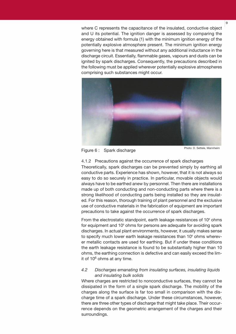
where C represents the capacitance of the insulated, conductive objectand U its potential. The ignition danger is assessed by comparing theenergy obtained with formula (1) with the minimum ignition energy of thepotentially explosive atmosphere present. The minimum ignition energygoverning here is that measured without any additional inductance in thedischarge circuit. Essentially, flammable gases, vapours and dusts can beignited by spark discharges. Consequently, the precautions described inthe following must be applied wherever potentially explosive atmospherescomprising such substances might occur.
Figure 6 : Spark discharge
4.1.2 Precautions against the occurrence of spark dischargesTheoretically, spark discharges can be prevented simply by earthing allconductive parts. Experience has shown, however, that it is not always soeasy to do so securely in practice. In particular, movable objects wouldalways have to be earthed anew by personnel. Then there are installationsmade up of both conducting and non-conducting parts where there is astrong likelihood of conducting parts being installed so they are insulat-ed. For this reason, thorough training of plant personnel and the exclusiveuse of conductive materials in the fabrication of equipment are importantprecautions to take against the occurrence of spark discharges.
From the electrostatic standpoint, earth leakage resistances of 106 ohmsfor equipment and 108 ohms for persons are adequate for avoiding sparkdischarges. In actual plant environments, however, it usually makes senseto specify much lower earth leakage resistances than 106 ohms wherev-er metallic contacts are used for earthing. But if under these conditionsthe earth leakage resistance is found to be substantially higher than 10ohms, the earthing connection is defective and can easily exceed the lim-it of 106 ohms at any time.
4.2 Discharges emanating from insulating surfaces, insulating liquidsand insulating bulk solids
Where charges are restricted to nonconductive surfaces, they cannot bedissipated in the form of a single spark discharge. The mobility of thecharges along the surface is far too small in comparison with the dis-charge time of a spark discharge. Under these circumstances, however,there are three other types of discharge that might take place. Their occur-rence depends on the geometric arrangement of the charges and theirsurroundings.
Photo: D. Settele, Mannheim
elektrostatik_e_feb_2015_Manual 09.02.15 09:32 Seite 9

104.2.1 Brush and corona discharges
If charges of one polarity are distributed on the surface of an insulator, so-called corona or brush discharges can occur as soon as the surface of anearthed electrode – such as a person's finger – nears the surface. In thiscase the electric field strength on the electrode surface is raised so muchthat the dielectric strength of air (approx. 3 MV/m under normal condi-tions) is reached. Whether a corona or a brush discharge occurs dependson a number of factors, such the electrode's radius of curvature, thespeed at which the electrode approaches, and the polarity of the surfacecharges. But it can usually be assumed that corona discharges will occuronly if the electrode's radius of curvature is less than 0.5 mm. For radiigreater than 5 mm, the probability that brush discharges will occur is verygreat. For hazard assessment, the worst-case scenario of a brush dis-charge – which are much more incendive – should always be assumed.
Figure 7: Brush discharge
But brush discharges do not occur only in connection with highly chargedinsulating surfaces of plastics. Indeed, they must be expected wheneveran earthed, conductive electrode enters a high-strength electric field. Theelectric field may be created by a highly charged insulating liquid or sus-pension, a mist, a pile of insulating bulk solids, or a dust cloud.
The characteristic properties and incendivity of brush discharges havebeen studied by many authors [9, 16]. The figures stated in the literaturefor the equivalent energy of brush discharges, which were determined withexplosive gas/air mixtures, are on the order of a few millijoules. The incen-divity of bush discharges depends on the electrode's radius of curvature,the polarity of the electric field, and – if the electric field emanates from acharged plastics surface – the surface charge density and size of thecharged surface area.Based on the empirically determined figures for the equivalent energy ofbrush discharges, it must be assumed that most potentially explosivegas/air mixtures, solvent-vapour/air mixtures and hybrid mixtures can beignited by brush discharges. Even though the minimum ignition energy of
Photo: D. Settele, Mannheim
elektrostatik_e_feb_2015_Manual 09.02.15 09:32 Seite 10

11
certain dusts is less than a few millijoules, no ignitions of dust clouds bybrush discharges have ever been reported. On the basis of the presentstate of knowledge, therefore, brush discharges are very unlikely to ignitepure dust clouds containing no flammable gases or vapours. It followsthat efforts should be taken to exclude brush discharges wherever poten-tially explosive gas/air or vapour/air mixtures can occur.
Figure 8: Corona discharge
4.2.2 Preventive measures against brush and corona dischargesBrush and corona discharges emanating from apparatus, hardware, con-tainers and packing materials can be excluded by using conductive mate-rials or by restricting the size of chargeable surfaces. The term "antistat-ic" is often used in this connection. In the German literature, the precise-ly defined property "unchargeable" is the nearest equivalent to "antistatic".A surface is considered unchargeable if its surface resistance measuredunder standard atmospheric conditions is less than 109 ohms. No brushdischarges are expected under these conditions. Besides surface resist-ance, the charge decay time is also used to characterize the dischargebehaviour of surfaces.
The inclusion of "antistatic" additives in polymers is a frequently usedmethod of improving the charge dissipation behaviour of chargeable sur-faces. These additives make it possible to lower the surface resistance tolevels within the band mentioned above. One trouble with this method,though, is that the effectiveness of the antistatic additives depends heav-ily on the relative humidity of the ambient air; another is that the antistat-ic agents tend to be absorbed by substances in contact with the treatedsurfaces.The volume conductivity of polymers can be increased by several ordersof magnitude by including carbon powder in the compound in the rightquantity, fineness and dispersion. Plastics thus modified are regarded asconductive from the electrostatic standpoint and have to be earthed inpractice.
Because of the electrostatic induction effect, chargeable surfaces that arebacked by a conductive, earthed layer (as in the case of metal surfacescoated with an insulator) will not emit any brush discharges. The sameapplies to walls of insulating material, provided at least one side has beenrendered unchargeable, i.e. antistatic. But brush discharges can only be
Photo: D. Settele, Mannheim
elektrostatik_e_feb_2015_Manual 09.02.15 09:32 Seite 11

12
ruled out with certainty in these cases if the layer or wall thickness doesnot exceed precisely defined limits and the conductive (i.e. unchargeable)surface cannot peel away from the rest of the lamination.
4.2.3 Propagating brush dischargesIf the charges are not arranged in the form of a single charged layer of onepolarity but as a double layer of charges of opposite polarity on the oppos-ing surfaces of an insulating sheet, propagating brush discharges canoccur. They are caused by an electrical short circuit between the twooppositely charged surfaces of the sheet. Such short circuits can becaused either by the approach of two electrically connected electrodes tothe respective surfaces or by electric or mechanical perforation of insu-lating sheet. The discharge pattern is always the same: many dischargechannels propagate outward along the surface from the short-circuit pointlike the spokes of a wheel. Though they all come together in a bright cen-tral discharge channel – between the approaching electrodes in the caseof an external short circuit or through the perforated sheet – the resultingbrush discharge emanates from the entire surface of the sheet on bothsides.
Figure 9: Propagating brush discharge
For a long time it was assumed that these discharges occurred only if oneside of the sheet was in solid contact with an earthed metal surface. Theidea was that the other charged layer of opposite polarity was createdautomatically by electrostatically induced charges. But by "spraying" onthe second charge layer with corona discharges, it is easy to demonstratethat an earthed metal surface is not absolutely essential to formation ofthe two charged layers. If the insulating wall of a drum or containerbecomes highly charged on the inside, the electric field will normally bedirected outward through the wall toward earth. It can trigger externalcorona discharges that result in the outer wall becoming charged withopposite polarity. This sort of charging mechanism can be observed, forexample, during the filling of an insulating container with highly charged,insulating bulk solids.
Photo: D. Settele, Mannheim
elektrostatik_e_feb_2015_Manual 09.02.15 09:32 Seite 12

13
On the basis of practical experience and the results of empirical studies,it can be assumed that the kind of high surface charge densities requiredto trigger propagating brush discharges cannot be caused by manual sep-aration processes such as the wiping of insulating surfaces or the dump-ing of powder out of a plastic sack. Such high surface charge densitiescan be built up only by the extremely rapid separation processes occur-ring, for example, in the pneumatic transport of bulk solids through insu-lating pipes or through conductive pipes with an insulating internal coat-ing of high dielectric strength.
The energy released by propagating brush discharges is normally suffi-cient to ignite potentially explosive gas/air, solvent-vapour/air, and dust/airmixtures. Persons may suffer serious shock if, for example, they initiate apropagating brush discharge by inadvertently touching a highly chargedsurface. Efforts must be taken to exclude this kind of discharge wherev-er potentially explosive gas, vapour or dust atmospheres can form.
4.2.4 Preventive measures against propagating brush dischargesPropagating brush discharges are excluded by using conductive materi-als or using insulating materials of low dielectric strength at all locationswhere high surface charge densities might occur. Wherever an insulatingwall or coating reduces the puncture voltage to less than 4 kV, no propa-gating brush discharges can occur.
4.2.5 Cone dischargesBesides spark discharges emanating from charged, conductive productand brush or corona discharges emanating from charged, insulating prod-uct, there is another type, the so-called cone discharge. These dischargesare observed in connection with charged and highly insulating bulk solidsfilled into silos and containers. They occur in the form of discharge chan-nels directed radially outward, or in special cases right through the coneof material. Cone discharges can ignite potentially explosive gas, vapouror dust atmospheres. Their incendivity (equivalent ignition energy) increas-es with rising silo diameter and with increasing particle size of the bulkmaterial in which the cone discharge occurs [12-14].
4.2.6 Preventive measures against cone dischargesPrevention of the accumulation of high charge levels in bulk solids filledinto containers is the only dependable measure against the occurrence ofcone discharges. At volume resistivities of the bulk solids up to about 1010
ohms·m, the use of conductive, earthed silos ensures sufficiently rapidcharge dissipation. For higher volume resistivities, the accumulation ofdangerously high charges cannot be excluded for certain filling methodsand filling rates. Because there is usually no practical way to raise the con-ductivity of the bulk material, it is necessary to resort to other explosionprotection measures in cases where cone discharges cannot be reliablyexcluded and the expected equivalent energy is equal to or greater thanthe minimum ignition energy of the product being processed. One is theexclusion of potentially explosive atmospheres (e.g. by excluding flam-mable gases, vapours and fine dust, or by reducing the oxygen level), andanother is the application of constructive explosion protection.
elektrostatik_e_feb_2015_Manual 09.02.15 09:32 Seite 13

144.2.7 Lightning-like discharges
Before anything was known about cone discharges, charged dust cloudswere regarded as the major electrostatic hazard in silos and containers.This speculation stemmed from the observation of lightning bolts in dustand ash clouds during volcanic eruptions. More recently, systematic inves-tigations in a 60 m3 bunker led to the conclusion – which is supported bypractical experience to date – that the occurrence of lightning-like dis-charges is very unlikely in commercial-scale industrial installations.
5. Directive 94/9/EC and electrostatic ignition hazards
European Directive 94/9/EC, also known as ATEX 95 [17], stipulates indetail that equipment and protective systems used for their intended pur-poses in potentially explosive areas are not allowed to constitute an igni-tion hazard. This also applies expressly to nonelectrical equipment(Appendix II Section 1.0.1). It follows that these pieces of equipment andprotective systems are not allowed to present an ignition hazard as a resultof electrostatic discharges. This particular aspect is addressed in Appen-dix II Section 1. In detail, the requirements cover:
– Avoidance of ignition sources in general (Sections 1.0.1 and 1.0.2)– Selection of appropriate material (Sections 1.1.1 and 1.1.3)– Operating principle and design (Section 1.2.1)– Possible sources of ignition (Section 1.3), in particular electrostatic
charge (Section 1.3.2)
It is stipulated further that no ignition hazards should arise, either, in theevent of malfunctions or as a result of ageing.
The requirements stipulated in ATEX 95a for avoiding ignition hazards asa result of electrostatic charges on equipment and protective systems dealprimarily with excluding spark and brush discharges. As explained in sec-tions 4.1.2 and 4.2.2 of this article, spark discharges are excluded byearthing all conductive parts and incendive brush discharges are exclud-ed by
– increasing the surface conductivity of insulating surfaces – restricting the size of insulating surfaces– limiting the layer thickness of insulating coatings
The relevant requirements are summarized in Table 1. Thin insulating coat-ings on conductive, earthed surfaces are admissible in all zones, provid-ed the thickness does not exceed 2.0 mm or 0.2 mm in the cases of gas-es or vapours of Groups IIA and IIB or IIC respectively [11, 17, 18, 19].
elektrostatik_e_feb_2015_Manual 09.02.15 09:32 Seite 14

156. Risk assessment and the exclusion of static electricity in the
harmonized standards
As already noted in section 3 "Systematic procedure for evaluating igni-tion hazards created by electrostatic charges", assessment of the occur-rence and incendivity of discharges in all sorts of actual situations is themost important and also the most difficult step in analyzing hazards cre-ated by electrostatic charges. For this reason, Table 1 recapitulates theincendivities of the various types of discharge occurring in practice. Bynow, sufficient experience and knowledge have been accumulated tomake such assessments in cases where the necessary underlying dataare available. The data required for a reliable analysis are exact knowledgeof the properties of the potentially explosive mixture that may be present,the resistances or conductivities of the substances, apparatus, packingmaterials and personal equipment in use, volumes and geometric arrange-ment of the installations and technical devices, and precise knowledge ofthe existing earth leakage and equipotential bonding conditions.
Table 1: Incendivities of the different discharge types
6.1 Fundamentals and methodology of explosion protection EN 1127-1:2008 (Sections 5.3.7 and 6.4.4) [3]
6.1.1 Risk assessmentIncendive discharges of static electricity can occur under certain condi-tions. For example, discharges from charged conductive parts installedso as to be insulated can easily result in incendive sparks. Charged partsof nonconductive materials, such as most plastics and certain other mate-rials, can produce brush discharges. In some cases involving rapid sep-aration (such as transmission belts, film webs passing over rollers) or com-binations of conductive and nonconductive materials, propagating brushdischarges are possible as well. Other possible types of dischargesinclude cone discharges (in bulk solids) and lightning-like discharges.
Brush discharges can ignite practically any kind of potentially explosivegas or vapour atmosphere. Based on the current state of knowledge,brush discharges are not capable of igniting potentially explosive dust/airmixtures even not those with extremely low minimum ignition energy lev-els [16]. Sparks, propagating brush discharges, cone discharges and light-ning-like discharges with sufficiently high energies can ignite any kind ofpotentially explosive atmosphere.
6.1.2 Preventive measures against ignition hazards caused by staticelectricity
Wherever static electricity hazards are found to exist, installations, pro-
Type of discharge
Incenditvity
Gases, vapours Dust
MZE < 0.025 mJ MZE > 0.025 mJ
Spark discharge + + +
Needle-point discharge + - -
Brush discharge + + -
Propagating brush discharge + + +
Cone discharge + + +
Lightning-like discharge + + +
elektrostatik_e_feb_2015_Manual 09.02.15 09:32 Seite 15

16
tective systems and components must satisfy the following requirementsfor the different categories:
6.1.2.1 All categoriesThe most important protective measure is to connect and earth all con-ductive parts that might become dangerously charged. However, if non-conductive parts and materials are present, this is not enough. In suchcases, dangerous charging of nonconductive parts and substances(including solids, liquids and dusts) has to be excluded. Information per-taining to this must be included in the respective instruction manuals.
6.1.2.2 Category 1Incendive discharges even have to be excluded in the event of infrequentlyoccurring malfunctions.
6.1.2.3 Category 2Incendive discharges must be excluded during normal operation of theinstallations, including servicing and cleaning, as well as during relativelycommon malfunctions.
6.1.2.4 Category 3Preventive measures other than earthing are usually only required in cas-es where incendive discharges occur frequently (insufficiently conductivetransmission belts, for instance).
6.2 Requirements for electrical equipment in Group II (IEC 60079-0) [18]
In the new 2007 version of IEC 60079-0 the requirements for electricalequipment of the Equipment Protection Levels Ga, Gb and Gc have beencombined for all types of protection.
6.2.1 Protective measuresThe electrical equipment shall be built in such a way that ignition hazardscaused by electrostatic charges are excluded during normal use, servic-ing and cleaning. This requirement shall be fulfilled by means of one of thefollowing measures:
a) by appropriate selection of the material to ensure that the surfaceresistance of the enclosure, measured according to the methodspecified described in the standard, does not exceed 109 ohms at (23± 2) °C and (50 ± 5) % relative humidity,
b) or by limiting the surface area of non-metallic enclosure part
Table 2: max. permissible surface surface area
The values stated above for the maximum permissible surface area maybe exceeded by the factor 4 if the non-metallic enclosure parts areenclosed by a conductive, earthed frame.
EPLMax. permissible surface area [mm²]
IIA IIB IIC
Ga 5000 2500 400
Gb 10000 10000 2000
Gc 10000 10000 2000
elektrostatik_e_feb_2015_Manual 09.02.15 09:32 Seite 16

17
Alternatively, the surfaces of elongated parts with non-metallic surfaces,such as pipes or ropes, need not be taken into consideration if the diam-eter or the width does not exceed the values laid down in the table. Elec-tric cables are excluded from this requirement.
Table 3: max. permissible diameter
c) by the limitation of a non-metallic layer that is bonded to a conduc-tive, earthed surface (for example, foils on operator panels or key-boards).
Table 4: max permissible thickness
d) by the limitation of the charge transfer or by the inability to store ahazardous charge in accordance with the method specified in thestandard.
If the ignition hazard cannot be excluded by the appropriate design of theequipment, a warning sign must be affixed drawing attention to the safe-ty precautions to be taken in the plant
6.3 Requirements for electrical equipment in Group III (IEC 60079-0) [18]
The new Equipment Group III for dusts was also introduced in the new2007 version of IEC 60079-0. The requirements apply to the EquipmentProtection Levels Da, Db and Dc.
6.3.1 Protective measuresThe electrical equipment shall be built in such a way that ignition hazardscaused by propagating brush discharges are excluded during normal use,servicing and cleaning. This requirement shall be fulfilled by means of oneof the following measures:
a) by appropriate selection of the material to ensure that the surfaceresistance of the enclosure, measured according to the methodspecified described in the standard, does not exceed 109 ohms at (23± 2) °C and (50 ± 5) % relative humidity;
b) a breakdown voltage ≤ 4 kV (measured through the thickness of theinsulatingmaterial according to the method specified in IEC 60243-1);
c) layer thickness of external insulations on metal parts ≥ 8 mm. (In thecase of an external plastic layer measuring 8 mm or more in thick-ness on metal parts such as detector probes or similar installationparts, propagating brush discharges are not to be expected. The
EPLMax. permissible diameter or width [mm]
IIA IIB IIC
Ga 3 3 1
Gb 30 30 20
Gc 30 30 20
EPLMax. permissible thickness [mm]
IIA IIB IIC
Ga 2 2 0.2
Gb 2 2 0.2
Gc 2 2 0.2
elektrostatik_e_feb_2015_Manual 09.02.15 09:32 Seite 17
18amount of wear to be expected during normal operation shall be tak-en into account during the determination and evaluation of the min-imum layer thickness of the insulator.);
d) by limitation of the charge transfer in accordance with the methodspecified in the standard.
6.4 Requirements for electrical installations in explosive atmospheres(IEC 60079-14) [19]
The requirements according to IEC 60079-0 have been taken over in thenew installation standard. During installation, auxiliary parts such as plas-tic plates and pipes are used for fixing electrical apparatus. The require-ments for apparatus shall also apply to the auxiliary parts.
6.5 Non-electrical equipment for use in explosive atmospheres (EN 13463-1) [20]
Enclosures of Category 1 and Category 2 equipment shall be designed insuch a way that the danger of ignition is excluded during normal opera-tion, servicing and cleaning. This requirement shall be met by applyingone of the following measures:
a) by the appropriate selection of the material to ensure that the surfaceresistance of the enclosure, measured according to the methodspecified in the standard, does not exceed 109 ohms at (23 ± 2) °Cand (50 ± 5) % relative humidity;
b) by the size, shape and arrangement or other protective measures, sothat the occurrence of such hazardous electrostatic charges is avoid-ed. In the case of equipment in the Category 2G, this requirementcan be fulfilled by carrying out the test according to EN 13463-1,Appendix C, provided that no propagating brush discharges canoccur (propagating brush discharges are considered to be effectiveignition sources for gas, vapour, mist and dust/air mixtures. Propa-gating brush discharges can occur after the high charging of non-conductive layers or coatings on metallic surfaces and, in the caseof equipment in Groups I and II, they can be prevented by ensuringa breakdown voltage of the layers of less than 4 kV. In the case ofapparatus in Group II D, which may only be used in dust atmos-pheres with a minimum ignition energy of more than 3 mJ (measuredwith a capacitive discharge), incendive electrostatic discharges,including propagating brush discharges, can also be prevented byensuring that the thickness of the non-conductive layers is more than10 mm);
c) or by limiting the projected surface areas in any direction of non-con-ductive parts of equipment that can become electrostaticallycharged, provided that no propagating brush discharges can occur.
elektrostatik_e_feb_2015_Manual 09.02.15 09:33 Seite 18

19
1 The unit of measurement cm² is not a standard ISO unit. Note: in all IEC standards the unitsof measurement have been converted to mm² according to ISO.
2 As brush discharges are not capable of igniting the dusts, the limiting values in this table inaccordance with EN 13463-1 for chargeable surfaces do not make any sense.
3 In the case of Category 3 it shall be noted that, in the event of the occurrence of incendivedischarges during operation, special measures shall be taken. Unfortunately, the same phi-losophy as in the IEC standards 60079-0 was not applied in the standard EN 13463-1 fornon-electrical equipment. In the IEC standards the maximum permissible values also haveto be observed for Category 3 (Equipment Protection Levels 3G and 3D).These require-ments can be relaxed provided that suitable proof is provided.
Table 5: Permissible surface areas for non-conductive parts ofequipment
If the flat plastic surfaces exposed to rubbing are enclosed by a con-ductive,earthed frame, these values can bemultiplied by a factorof 4.In the case of Category 3, it shall be noted that, in the event of theoccurrence of incendive discharges during operation, special mea-sures shall be taken. Unfortunately, the same philosophy as in theIEC standards was not applied in the EN standards for non-electricalequipment. In the IEC standards the maximum permissible valuesalso have to be observed for Category 3 (Equipment ProtectionLevels 3G and 3D). These requirements can be relaxed provided thatsuitable proof is provided.
Further information on this subject is provided in CENELEC TechnicalReport RO44-001 "Safety of machinery – guidance and recommendationsfor the avoidance of hazards due to static electricity" [11].
CategoryPermissible surface area in cm² 1
Dust2 IIA IIB IIC
1 250 50 25 4
2 500 100 100 20
3 no limits3 no limits3 no limits3 no limits3
elektrostatik_e_feb_2015_Manual 09.02.15 09:33 Seite 19

20Literature References
[1] W. Bartknecht, Explosionsschutz, Grundlagen und Anwendung,Springer Publishers Berlin, Heidelberg, New York,1993.
[2] Handbuch des Explosionsschutzes (Published by Henrikus Steen),Wiley-VCH; 1. Auflage (April 2000)
[3] European Standard EN 1127-1:2007 Explosive Atmospheres – Explo-sion Prevention and Protection – Part 1: Basic Concepts and Metho-dology.
[4] Glor, "Electrostatic Hazards in Powder Handling", Research StudiesPress Ltd., Letchworth, Hertfordshire, England, 1988.
[5] Lüttgens and M. Glor, "Statische Elektrizität begreifen und sicherbeherrschen", Expert Verlag, Ehningen bei Böblingen, 1993.
[6] J.A. Cross, "Electrostatics - Principles, Problems and Applications",IOP Publishing Ltd., Bristol, 1987.
[7] ESCIS Publication Series "Statische Elektrizität, Regeln für diebetriebliche Sicherheit" Vol. 2, Edition 1997, available from SektionChemie, Abteilung Arbeitssicherheit, SUVA, Fluhmattstrasse 1, CH-6002 Luzern.
[8] ISSA Prevention Series No. 2017 (G) "Statische Elektrizität Zündge-fahren und Schutzmassnahmen" Internationale Sektion der IVSS fürdie Verhütung von Arbeitsunfällen und Berufskrankheiten in der che-mischen Industrie der internationalen Vereinigung für soziale Sicher-heit (IVSS), 1995. ISBN 92-843-70914, ISSN 1015-8022.
[9] TRBS 2153 (former BGR132) Technische Regel Betriebssicherheit2153, Vermeidung von Zündgefahren infolge elektrostatischer Aufla-dungen (Germany) 2009
[10] Code of Practice for Control of Undesirable Static Electricity. B.S.5958, Part 1 and 2, British Standards Institution, London.
[11] CENELEC Report R044-001 "Safety of machinery – guidance andrecommendations for the avoidance of hazards due to static electri-city", 1998.
[12] M. Glor und B. Maurer, Fortschritt-Berichte VDI, Reihe 3 Nr. 181, VDI-Verlag, Düsseldorf, 1989.
[13] M. Glor and B. Maurer, Fortschritt-Berichte VDI, Reihe 3 Nr. 389, VDI-Verlag, Düsseldorf, 1995.
[14] M. Glor und K. Schwenzfeuer, Journal of Electrostatics 40&41 (1997)511.
[15] M. Glor, Journal of Electrostatics 63 (2005) 447.[16] M. Glor und K. Schwenzfeuer Journal of Electrostatics 63 (2005) 463.[17] ATEX Directive 94/9/EC – Equipment and protective systems intend-
ed for use in potentially explosive atmospheres.[18] IEC 60079-0 Explosive atmospheres – Part 0: Equipment – General
requirements[19] IEC 60079-14 Explosive atmospheres – Part 14: Electrical installa-
tions design, selection and erection[20] EN 13463-1 Non-electrical equipment for potentially explosive
atmospheres – Part 1: Basic method and requirements
elektrostatik_e_feb_2015_Manual 09.02.15 09:33 Seite 20

21Index
1 Introduction 3
1.1 Explosion hazards in industrial processes 31.2 Electrostatic charge as ignition source 3
2. Creation of electrostatic charges 4
3. Systematic procedure for evaluating ignition hazards created by electrostatic charges 5
4. Discharges – occurrence and incendivity 8
4.1 Discharges emanating from insulated conductors 84.1.1 Spark discharges 84.1.2 Precautions against the occurrence of spark discharges 9
4.2 Discharges emanating from insulating surfaces, insulating liquids and insulating bulk solids 9
4.2.1 Brush and corona discharges 104.2.2 Preventive measures against brush and corona discharges 114.2.3 Propagating brush discharges 124.2.4 Preventive measures against propagating brush discharges 134.2.5 Cone discharges 134.2.6 Preventive measures against cone discharges 134.2.7 Lightning-like discharges 13
5. Directive 94/9/EC and electrostatic ignition hazards 14
6. Risk assessment and the exclusion of static electricity in the harmonized standards 15
6.1 Fundamentals and methodology of explosion protection EN 1127-1:2008 (Sections 5.3.7 and 6.4.4) 15
6.1.1 Risk assessment 156.1.2 Preventive measures against ignition hazards caused by
static electricity 15
6.2 Requirements for electrical equipment in Group II (IEC 60079-0) 16
6.2.1 Protective measures 16
6.3 Requirements for electrical equipment in Group III (IEC 60079-0) 17
6.3.1 Protective measures 17
6.4 Requirements for electrical installations in explosive atmospheres (IEC 60079-14) 18
6.5 Non-electrical equipment for use in explosive atmospheres (EN 13463-1) 18
Literature References 20
elektrostatik_e_feb_2015_Manual 09.02.15 09:33 Seite 21

Your partner for internationallycertified solutionsin explosion protection
Pipe and tank trace heating systems
– heating cables· heating cables with fixed resistors · mineral-insulated heating cables· self-limiting heating cables
– site installation – temperature monitoring systems· thermostats and safety temperature limiters
· electronic temperature controllers and safety cutouts
· remote controls for temperature controller
– resistance temperature detectors Pt-100 Category 1 G
– resistance temperature detectors Pt-100 Category 2 G
Installation material
– temporary bonding– earth monitoring system– terminals and junction boxes – motor protecting switches up to 63 A– safety switches 10 to 180 A(for indirect and direct tripping)
– plug-and-socket devices– socket outlets for clean rooms – control and indicating devices– customized control stations– cable reels– cable glands– fastening material
Accredited inspection body (SIS 145)
Extremely strict inspections are carried out toguarantee the correct operation and safety ofinstallations in hazardous areas. We carry outboth professional initial inspections and period-ic inspections. These consist of a documenta-tion and organisation check and a technicalinspection.
Service Facilities according to IECEx Scheme
As an IECEx Scheme service facility we are qua-lified to carry out repairs, overhauling and rege-neration work all over the world – even on equip-ment from other manufacturers.
Design and Production
Explosionproof multipurpose distribution, switching and control units
Categories 2 G and 2 D, protection types– flameproof enclosure «d»– increased safety «e»– pressurized enclosure «px»
Categories 3 G and 3 D, protection types– non-sparking «nA»– restricted breathing enclosure «nR»– pressurized enclosure «pz»
Categories 2 D and 3 Dfor areas at risk of dust explosions– protection by enclosure «tD»– type of protection «pD»
Accessories– digital displays– disconnect amplifiers– transmitter power packs– safety barriers– keyboard and mouse– monitor– industrial PC
Lamps
– portable lamps, Categories 1, 2 and 3– hand-held and machine lamps 5 to 58 W(fluorescent and LED)
– inspection lamps Category 1 (Zone 0)– fluorescent light fixtures 18 to 58 W (also with integrated emergency lighting)
– reflector lamps– safety lighting – flashing lamps– boiler flange lamps
Electric heaters for industrial applications
– heating of air and gases (up to 200 bar)– heating of liquids– reactor heating systems (HT installations)– heating of solids – special solutions
elektrostatik_e_feb_2015_Manual 09.02.15 09:33 Seite 22

thuba Ltd.thuba EHB Ltd.CH-4015 BaselSwitzerland
Phone +41 61 307 80 00Fax +41 61 307 80 10
E-mail [email protected] www.thuba.com
ISBN 978-3-905850-06-2
elektrostatik_e_feb_2015_Manual 09.02.15 09:33 Seite 24