ifs6x can g - download.gongkong.com
TRANSCRIPT

Technical documentation
Field bus protocol for the intelligent compact drive IclA IFx
CANopen DS301 Operating system:
Order no.: 0098441113185
Edition: -000, 05.03

IclA
IFX
-CA
Nop
en D
S30
1 E
ditio
n -0
00 V
ersi
on 0
5.03
Important information IFX-CANopen DS301
Important information
These compact drives are designed for general use. They are state of the art and are designed to be as safe as possible. However, drives and drive controllers that are not specifically designed for safety functions are not approved for applications where the functioning of the drive could endanger persons. The possibility of unexpected or unbraked movements can never be totally excluded without additional safety equipment. For this reason personnel must never be in the danger zone of the drives unless additional suitable safety equipment prevents any personal danger. This applies for operating the machine during production and also for all service and maintenance work on drives and the machine. The machine design must ensure personal safety. Suitable measures for prevention of property damage are also required.
For more information see chapter 2, "Safety".

IFX-CANopen DS301 Table of contentsIc
lA IF
X-C
AN
open
DS
301
Edi
tion
-000
Ver
sion
05.
03
Table of contents
Important infomation
Table of contents
Written conventions and note symbols
1 Introduction
1.1 Documentation and literature . . . . . . . . . . . . . . . . . . . . 1-1
1.2 Directives and standards . . . . . . . . . . . . . . . . . . . . . . . 1-1
2 Safety
2.1 Qualifications of personnel . . . . . . . . . . . . . . . . . . . . . . 2-1
2.2 Intended use. . . . . . . . . . . . . . . . . . . . . . . . . . . . . . . . . 2-12.2.1 Ambient conditions . . . . . . . . . . . . . . . . . . . . . . . . . 2-12.2.2 Intended use . . . . . . . . . . . . . . . . . . . . . . . . . . . . . . 2-1
2.3 Safety instructions . . . . . . . . . . . . . . . . . . . . . . . . . . . . 2-22.3.1 Structure of the safety instructions . . . . . . . . . . . . . 2-2
3 Basics
3.1 CAN bus . . . . . . . . . . . . . . . . . . . . . . . . . . . . . . . . . . . . 3-1
3.2 CANopen technology . . . . . . . . . . . . . . . . . . . . . . . . . . 3-23.2.1 CANopen description language . . . . . . . . . . . . . . . 3-23.2.2 Communications layers . . . . . . . . . . . . . . . . . . . . . . 3-23.2.3 Objects . . . . . . . . . . . . . . . . . . . . . . . . . . . . . . . . . . 3-33.2.4 CANopen profiles . . . . . . . . . . . . . . . . . . . . . . . . . . 3-4
3.3 Field bus devices in the CAN bus . . . . . . . . . . . . . . . . 3-6
3.4 Operating modes and functions in field bus operation . . . . . . . . . . . . . . . . . . . . . . . . . . . . 3-6
4 CANopen communication
4.1 Communications profile . . . . . . . . . . . . . . . . . . . . . . . . 4-14.1.1 Communications objects . . . . . . . . . . . . . . . . . . . . . 4-14.1.2 Communications relationships . . . . . . . . . . . . . . . . 4-7
4.2 Service data communication (SDO communication) . . . . . . . . . . . . . . . . . . . . . . . . 4-10
4.2.1 Overview . . . . . . . . . . . . . . . . . . . . . . . . . . . . . . . . 4-104.2.2 SDO data exchange . . . . . . . . . . . . . . . . . . . . . . . 4-104.2.3 SDO message. . . . . . . . . . . . . . . . . . . . . . . . . . . . 4-114.2.4 Writing and reading SDO data . . . . . . . . . . . . . . . 4-12
4.3 Process data communication PDO communication) . . . . . . . . . . . . . . . . . . . . . . . . . 4-15
4.3.1 PDO data exchange . . . . . . . . . . . . . . . . . . . . . . . 4-154.3.2 Dynamic and static PDO mapping . . . . . . . . . . . . 4-204.3.3 Receive PDO R_PDO
(master → compact drive) . . . . . . . . . . . . . . . . . . 4-214.3.4 Send PDO T_PDO4 (compact drive → master) . 4-24
4.4 Emergency service. . . . . . . . . . . . . . . . . . . . . . . . . . . 4-28
C-1

Table of contents IFX-CANopen DS301
IclA
IFX
-CA
Nop
en D
S30
1 E
ditio
n -0
00 V
ersi
on 0
5.03
4.5 Synchronisation . . . . . . . . . . . . . . . . . . . . . . . . . . . . . 4-304.5.1 Synchronisation periods . . . . . . . . . . . . . . . . . . . . 4-304.5.2 Synchronous data transmission . . . . . . . . . . . . . . 4-31
4.6 Network management objects . . . . . . . . . . . . . . . . . . 4-324.6.1 NMT services for controlling the compact drive. . . 4-334.6.2 NMT services for connection monitoring . . . . . . . . 4-35
5 Installation and setup
5.1 Installation . . . . . . . . . . . . . . . . . . . . . . . . . . . . . . . . . . 5-1
5.2 Commissioning field bus connection . . . . . . . . . . . . . . 5-15.2.1 Starting field bus operation . . . . . . . . . . . . . . . . . . . 5-15.2.2 Troubleshooting. . . . . . . . . . . . . . . . . . . . . . . . . . . . 5-2
6 Examples for field bus operation
6.1 Overview. . . . . . . . . . . . . . . . . . . . . . . . . . . . . . . . . . . . 6-1
6.2 Using SDO commands . . . . . . . . . . . . . . . . . . . . . . . . . 6-36.2.1 Writing parameters . . . . . . . . . . . . . . . . . . . . . . . . . 6-36.2.2 Read parameter . . . . . . . . . . . . . . . . . . . . . . . . . . . 6-46.2.3 Synchronous errors . . . . . . . . . . . . . . . . . . . . . . . . . 6-5
6.3 Changing operating states with PDO4 . . . . . . . . . . . . . 6-66.3.1 Switch power amplifier on and off . . . . . . . . . . . . . . 6-66.3.2 Triggering Quick-Stop . . . . . . . . . . . . . . . . . . . . . . . 6-86.3.3 Resetting errors. . . . . . . . . . . . . . . . . . . . . . . . . . . . 6-9
6.4 Examples for the operating states with PDO4 . . . . . . 6-106.4.1 Point-to-point mode – absolute positioning . . . . . . 6-116.4.2 Point-to-point mode – relative positioning . . . . . . . 6-136.4.3 Speed mode . . . . . . . . . . . . . . . . . . . . . . . . . . . . . 6-146.4.4 Dimension setting . . . . . . . . . . . . . . . . . . . . . . . . . 6-156.4.5 Reference movement . . . . . . . . . . . . . . . . . . . . . . 6-16
6.5 Error signalling via PDO4 . . . . . . . . . . . . . . . . . . . . . . 6-176.5.1 Synchronous errors . . . . . . . . . . . . . . . . . . . . . . . . 6-176.5.2 Asynchronous errors . . . . . . . . . . . . . . . . . . . . . . . 6-18
7 Diagnosis and troubleshooting
7.1 Field bus communication error diagnosis . . . . . . . . . . . 7-1
7.2 Error messages . . . . . . . . . . . . . . . . . . . . . . . . . . . . . . 7-17.2.1 Synchronous errors . . . . . . . . . . . . . . . . . . . . . . . . . 7-17.2.2 Asynchronous errors . . . . . . . . . . . . . . . . . . . . . . . . 7-37.2.3 Errors in operational control via PDOs . . . . . . . . . . 7-4
8 Service
8.1 Service address . . . . . . . . . . . . . . . . . . . . . . . . . . . . . . 8-1
9 Object directory
9.1 Overview. . . . . . . . . . . . . . . . . . . . . . . . . . . . . . . . . . . . 9-19.1.1 Specifications for the objects. . . . . . . . . . . . . . . . . . 9-19.1.2 Objects, overview . . . . . . . . . . . . . . . . . . . . . . . . . . 9-2
9.2 Objects of the compact drive . . . . . . . . . . . . . . . . . . . . 9-4
C-2

IFX-CANopen DS301 Table of contentsIc
lA IF
X-C
AN
open
DS
301
Edi
tion
-000
Ver
sion
05.
03
10 Glossaries
10.1 Abbreviations . . . . . . . . . . . . . . . . . . . . . . . . . . . . . . . 10-1
10.2 Glossary . . . . . . . . . . . . . . . . . . . . . . . . . . . . . . . . . . . 10-2
Index
Supplement
C-3

Table of contents IFX-CANopen DS301
IclA
IFX
-CA
Nop
en D
S30
1 E
ditio
n -0
00 V
ersi
on 0
5.03
C-4

IFX-CANopen DS301 Written conventions and note symbolsIc
lA IF
X-C
AN
open
DS
301
Edi
tion
-000
Ver
sion
05.
03
Written conventions and note symbols
Instructions for use Layout and format:
Introduction to the following instruction steps
� This is the first step.
� This is the second step.
Explanation:
Instructions consist of an introduction and the actual instruction steps.
Unless otherwise stated, the individual instruction steps must be carried in the given sequence.
If an instruction step triggers a detectable reaction from the compact drive, the response is described after the step. In this way you can check that the step was correctly completed.
List symbol Layout and format:
Note on the contents of the list
• 1. list item
• 2. list item
– 1. list subitem
– 2. list subitem
• 3. list item
Explanation:
The actual list follows a note on the contents of the list. It can consist of 1 or 2 levels.
The list items are sorted alphanumerically or by priority.
User notes User notes contain general information, not safety information.
For an explanation of the safety instructions see chapter 2, "Safety".
This shows additional information on the current subject.
W-1

Written conventions and note symbols IFX-CANopen DS301
IclA
IFX
-CA
Nop
en D
S30
1 E
ditio
n -0
00 V
ersi
on 0
5.03
W-2

IFX-CANopen DS301 IntroductionIc
lA IF
X-C
AN
open
DS
301
Edi
tion
-000
Ver
sion
05.
03
1 Introduction
1.1 Documentation and literature
Documentation • Datasheets for IcIA in the IclA Intelligent Compact Drives catalogOrder no. 005 9941 2010 001 D Order no. 005 9941 2010 002 GB
• Controller manuals for IclA compact drives: - Intelligent Compact Drive Field Bus Stepper Motor IclA IFS6x Order no. 00 9844 1113 188 D Order no. 00 9844 1113 189 GB
Literature • Controller Area NetworkKonrad Etschberger, Carl Hanser Verlag ISBN 3-446-19431-2
• CANopen Holger Zeltwanger, VDE Verlag ISBN 3-8007-2448-0
1.2 Directives and standards
CANopen Standards CANopen documentation by the CAN in Automation (CiA) user organisation.
• ISO11898Controller Area Network CAN part 1...4
• EN50325Industrial Communication Subsystem based on ISO11898 for controller device interfaces
• CiA Draft Standard 301CANopen Application Layer and Communication Profile Version 4.02, February 2002, CAN in Automation e.V.
CAN interest group CAN in Automation (CiA)
Am Weichselgarten 26
D-91058 Erlangen
www.can-cia.de
Documentation and literature 1-1

Introduction IFX-CANopen DS301
IclA
IFX
-CA
Nop
en D
S30
1 E
ditio
n -0
00 V
ersi
on 0
5.03
1-2 Directives and standards
IFX-CANopen DS301 SafetyIc
lA IF
X-C
AN
open
DS
301
Edi
tion
-000
Ver
sion
05.
03
2 Safety
2.1 Qualifications of personnel
Only electrical and controller technicians qualified under IEV 826-09-01 (modified) are authorized to set parameters on, commission and operate the compact drive. The electrical and controller technicians must be familiar with the contents of this manual before starting work with and on the compact drive.
The electrical and controller technicians must have sufficient training, knowledge and experience to recognize and avoid dangers.
The technicians must be familiar with the current standards, regulations and work safety regulations that must be observed while working on and with the compact drive.
2.2 Intended use
2.2.1 Ambient conditions
See the approved environmental conditions described in the data sheet.
2.2.2 Intended use
The compact drive is a variable-speed drive with permanently excited synchronous motor (stepper motor), integrated controller and power electronics. As an option the compact drive can be fitted with a gearbox and a holding brake.
Another option is a Hall sensor, which sends an index pulse and can be used for blocking detection.
The compact drive may be used for industrial applications in the system configuration described with a fixed connection only.
The environment in which the compact drive is to be installed and operated must meet degree of protection IP54 as a minimum.
The compact drive must not be commissioned and operated until it has been installed in conformity with EMC requirements. The compact drive may only be used with the cables and accessories specified by your local dealer.
Qualifications of personnel 2-1
Safety IFX-CANopen DS301
IclA
IFX
-CA
Nop
en D
S30
1 E
ditio
n -0
00 V
ersi
on 0
5.03
2.3 Safety instructions
2.3.1 Structure of the safety instructions
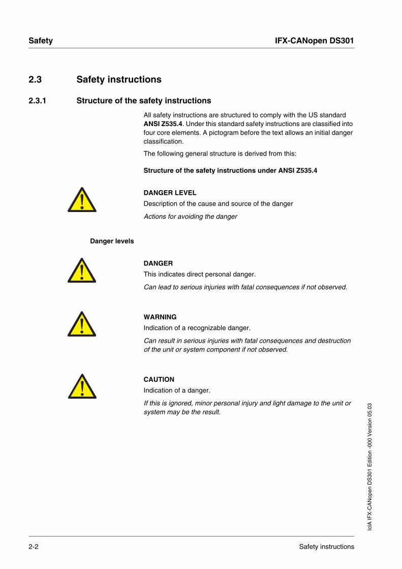
All safety instructions are structured to comply with the US standard ANSI Z535.4. Under this standard safety instructions are classified into four core elements. A pictogram before the text allows an initial danger classification.
The following general structure is derived from this:
Structure of the safety instructions under ANSI Z535.4
DANGER LEVEL
Description of the cause and source of the danger
Actions for avoiding the danger
Danger levels
DANGER
This indicates direct personal danger.
Can lead to serious injuries with fatal consequences if not observed.
WARNING
Indication of a recognizable danger.
Can result in serious injuries with fatal consequences and destruction of the unit or system component if not observed.
CAUTION
Indication of a danger.
If this is ignored, minor personal injury and light damage to the unit or system may be the result.
2-2 Safety instructions

IFX-CANopen DS301 BasicsIc
lA IF
X-C
AN
open
DS
301
Edi
tion
-000
Ver
sion
05.
03
3 Basics
3.1 CAN bus
The CAN bus (CAN: Controller Area Network) was originally developed for fast, economical data transmission in automotive engineering. In the meantime the CAN bus is also used in industrial automation technology and has been further developed for communication at field bus level.
Features The CAN bus is a standardized open bus, through which devices, sensors and actuators from different manufacturers communicate with each other. Features of the CAN bus are:
• Multimaster capacity Every device on the field bus can send and receive data independently without having to be assigned a "supervisory" master functionality.
• Message-oriented communication Devices can be linked into an existing network without requiring reconfiguration of the entire system. It is not necessary to set the address of a new device in the network.
• Prioritisation of messages Messages with higher priority are sent first for time-critical applications.
• Residual error probability Various backup processes in the network reduce the probability of
an undetected, faulty data transfer to less than 10-11. In practice, 100%-secure transmission can be assumed.
Transmission technology In the CAN bus multiple devices are connected via a bus cable. Every network device can send and receive messages. Data between network devices are transmitted serially.
Network devices Examples of CAN bus devices are
• automation devices, e.g. PLCs
• PCs
• input and output modules
• drive controllers
• analysis devices
• sensors and actuators
CAN bus 3-1

Basics IFX-CANopen DS301
IclA
IFX
-CA
Nop
en D
S30
1 E
ditio
n -0
00 V
ersi
on 0
5.03
3.2 CANopen technology
3.2.1 CANopen description language
CANopen is a device and manufacturer-independent network protocol for communication over a CAN bus. Originally CANopen was implemented in industry for controlling movement sequences, but now it is used in many different areas of network communications, such as medical technology, building automation and vehicle control.
3.2.2 Communications layers
CANopen uses the CAN bus technology for data communications. CANopen is based on the ISO-OSI layer model on the data communications basic network service. Three layers secure data communications in the CAN bus:
• CAN: physical layer
• CAN: data link layer
• CANopen: application layer
Fig. 3.1 CANopen layer model
Physical layer The physical layer defines the electrical properties of the CAN bus – such as plug connectors, cable length and properties, bit coding and bit timing.
3-2 CANopen technology

IFX-CANopen DS301 BasicsIc
lA IF
X-C
AN
open
DS
301
Edi
tion
-000
Ver
sion
05.
03
Data link layer The data link layer connects the network devices. It sets the priorities of individual data packets and monitors and corrects errors.
Application layer The application layer uses communication objects (Communication Objects = COB) for data exchange among the network devices. Communication objects are elementary components for creating a CANopen application.
3.2.3 Objects
All processes under CANopen are executed via objects. Objects perform various tasks. As communication objects they transport data to the field bus, control establishment of connections or monitor the network devices. As device-specific objects they are directly connected to the device. The device functions can be used and changed via the device-specific objects.
Object directory The object directory of a device is the central connection for all objects. All objects through which the other network devices can connect to the device are listed here.
Fig. 3.2 Device model with object directory
The object directory contains objects that describe the data types and execute communications tasks and device functions under CANopen.
CA
N b
us
Power amplifier
Kommunikation
Application
Specificfunctions
Objectdirectory
0000h0001h
.1000h
.2000h
.6000h
.FFFFh
DevicefunctionsProcess data
objects (PDO)
Service dataobjects (SDO)
SYNC, EMCY
Networkmanagement NMT
Layermanagement LMT
CANopen
Motor
communication
CANopen technology 3-3

Basics IFX-CANopen DS301
IclA
IFX
-CA
Nop
en D
S30
1 E
ditio
n -0
00 V
ersi
on 0
5.03
Object index Every object is addressed via a 16-bit index, which is shown as a 4-digit hexadecimal number. The objects are classified in groups in the object index.
A list of all objects that can be used for the compact drive under CANopen can be found in chapter 9, "Object directory".
Object group "data types" The messages that move over the network as bit streams have the same meaning for sender and receiver with the data types. Data types are agreed via the objects of the data types.
Object groups of the profiles CANopen objects carry out various tasks in field bus operation. Profiles combine the objects in accordance with their prescribed tasks.
3.2.4 CANopen profiles
Standardised profiles Standardised profiles describe objects that can be applied to various devices without additional configuration. The Interessengemeinschaft CAN in Automation e. V. (CiA) [CAN interest group] has standardized various profiles. They include:
• the DS301 communications profile
• the DSP402 "drives and motion profile" device profile
Fig. 3.3 CANopen reference model
Index (hex) Object groups Supported by drive
0000h reserved 0001h-009Fh static and complex data types 00A0h-0FFFh reserved 1000h-1FFFh communication profile, standardised in DS 301 Yes
2000h-5FFFh manufacturer-specific device profiles Yes
6000h-9FFFh standardised device profiles, e.g. in DSP 402 A000h-FFFFh reserved Table 3.1 Object index
CAN bus
Physical Layer
Data Link Layer
Application Layer
CANopen Communication Profile (CiA DS 301)
Device Profile for Drives and Motion Control (CiA DSP 402)
Application
3-4 CANopen technology
IFX-CANopen DS301 BasicsIc
lA IF
X-C
AN
open
DS
301
Edi
tion
-000
Ver
sion
05.
03
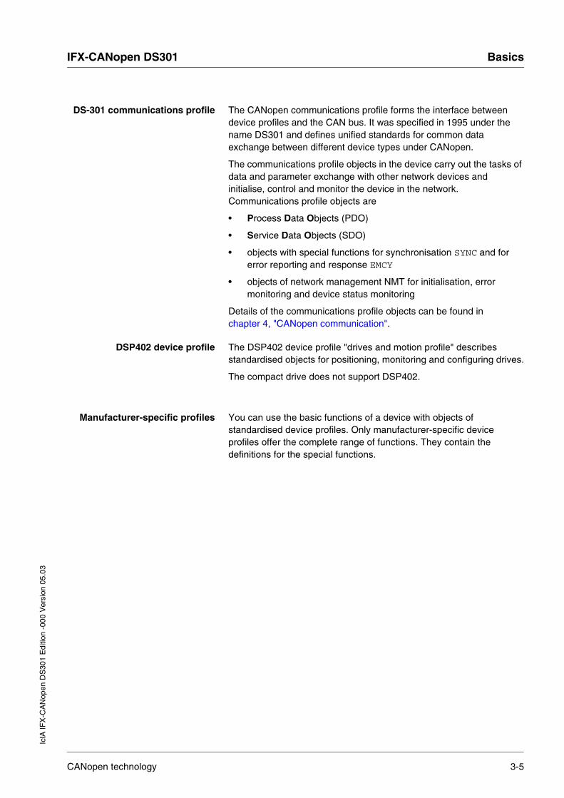
DS-301 communications profile The CANopen communications profile forms the interface between device profiles and the CAN bus. It was specified in 1995 under the name DS301 and defines unified standards for common data exchange between different device types under CANopen.
The communications profile objects in the device carry out the tasks of data and parameter exchange with other network devices and initialise, control and monitor the device in the network. Communications profile objects are
• Process Data Objects (PDO)
• Service Data Objects (SDO)
• objects with special functions for synchronisation SYNC and for error reporting and response EMCY
• objects of network management NMT for initialisation, error monitoring and device status monitoring
Details of the communications profile objects can be found in chapter 4, "CANopen communication".
DSP402 device profile The DSP402 device profile "drives and motion profile" describes standardised objects for positioning, monitoring and configuring drives.
The compact drive does not support DSP402.
Manufacturer-specific profiles You can use the basic functions of a device with objects of standardised device profiles. Only manufacturer-specific device profiles offer the complete range of functions. They contain the definitions for the special functions.
CANopen technology 3-5

Basics IFX-CANopen DS301
IclA
IFX
-CA
Nop
en D
S30
1 E
ditio
n -0
00 V
ersi
on 0
5.03
3.3 Field bus devices in the CAN bus
Different field bus devices from Berger Lahr can be operated in the same field bus segment. The CANopen bus offers a unified basis for exchanging commands and data between compact drives and other network devices.
Fig. 3.4 Field bus devices in the network
3.4 Operating modes and functions in field bus operation
This manual only described the protocol for the compact drive. You can find the description of the operating modes, operating functions and all parameters in the controller manual for the compact drive in the "Operation" and "Parameters" chapters:
Operating modes • speed mode
• point-to-point mode
• referencing
Operating functions • definition of direction of rotation
• creating movement profile
• Quick Stop
• fast position capture
Setting options The following settings can be made over the field bus:
• reading and writing parameters
• monitoring inputs and outputs of the 24-V signal interface
• activating diagnostics and error monitoring functionsfield bus mode
IclAcompact drives
Twin Linecontroller
L
N
PC SPS
3-6 Field bus devices in the CAN bus

IFX-CANopen DS301 CANopen communicationIc
lA IF
X-C
AN
open
DS
301
Edi
tion
-000
Ver
sion
05.
03
4 CANopen communication
4.1 Communications profile
4.1.1 Communications objects
CANopen manages communications between the network devices with object directories and objects. With Process Data Objects (PDO) and Service Data Objects (SDO) a network device can request the object data from the object directory of another network device and – if permissible – write modified values.
You can exchange parameter values, start movement functions of specific CANopen bus devices or query status information by access to the objects of the network devices.
Every CANopen network device administers an object directory in which all objects for communication with it are listed.
Index, subindex The objects are addressed in the object directory with a 16-bit long index.
The individual data fields of an object are specified by the subindex entries. A data field consists of one or more subindex entries.
Index and subindex are shown in hexadecimal form, shown by the appended "h".
The following example shows index and subindex entries for the object receive PDO4 mapping, 1603 h for identification for the mapping
in R_PDO4.
Index Subindex Object Meaning
1603h 00h Number of elements Number of subindices
1603h 01h 1st mapped object R_PDO4 First object for the mapping in R_PDO4
1603h 02h 2nd mapped object R_PDO4 Second object for the mapping in R_PDO4
1603h 03h 3rd mapped object R_PDO4 Third object for the mapping in R_PDO4
Table 4.1 Examples of index and subindex entries
Communications profile 4-1

CANopen communication IFX-CANopen DS301
IclA
IFX
-CA
Nop
en D
S30
1 E
ditio
n -0
00 V
ersi
on 0
5.03
Directory structure The objects in the object directory are sorted by index values. Table 4.1, page 4-1 shows the index ranges of the object directory in accordance with the CANopen agreement.
Object descriptions in the manual
The objects of the following object groups are described differently for CANopen programming with a compact drive.
• 1xxxh objects: communications objects in this chapter
• 3xxxh objects: manufacturer-specific objects, where required for
controlling the compact drive.
All operating modes and operating functions are controlled by manufacturer-specific objects. These functions and objects are described in the relevant device documentation.
Index range (hex)
Object groups Supported by drive
0000h Reserved 0001h-001Fh Static data types 0020h-003Fh Complex data types 0040h-005Fh Manufacturer-specific data types 0060h-007Fh Status data types for the device profiles 0080h-009Fh Complex data types for the device profiles 00A0h-0FFFh Reserved 1000h-1FFFh Communications profile Yes
2000h-5FFFh Manufacturer-specific profiles Yes
6000h-9FFFh Standardised device profiles A000h-FFFFh Reserved
Table 4.2 Index ranges of the object directory
4-2 Communications profile

IFX-CANopen DS301 CANopen communicationIc
lA IF
X-C
AN
open
DS
301
Edi
tion
-000
Ver
sion
05.
03
The manufacturer-specific objects are stored from index range 3000h.
To derive the CAN index from the indices given in the device documentation, it is only necessary to add 3000h.
Fig. 4.1 Object groups
Example:
The control word for status change has the index 28 and the subindex 1 ⇒ in the CAN protocol access to index 301Ch (3000h + 1Ch [= 28d])
and subindex 1.
Overview The communications objects are standardised with the DS-301 CANopen communications profile. The objects can be classified into four groups according to their tasks.
• PDO (Process Data Objects)
– real-time transmission of process data
• SDO (Service Data Objects)
– write and read access to the object directory
• NMT (Network Management)
– initialisation and monitoring of the network
– error handling in the network
– monitoring of individual network devices
• special objects for controlling CAN messages
– object EMCY (Emergency) for displaying an error of a device or its peripherals
– object SYNC (Synchronisation) for synchronisation of network devices
Indices
1…993000h+
Manufacturer-specificobjects
3000h …5FFFh
CANopen
=
Parameter listsee controller manual
Communication objects
1000h …1FFFh
Communications profile 4-3

CANopen communication IFX-CANopen DS301
IclA
IFX
-CA
Nop
en D
S30
1 E
ditio
n -0
00 V
ersi
on 0
5.03
CAN message Data are exchanged on the CAN bus as CAN messages. A CAN message transmits the communications object and a variety of management and control information.
Fig. 4.2 CAN message and simplified display of CANopen message
CANopen message The CAN message can be displayed in simplified form for work with CANopen objects and for data exchange, because most of the bits are used to ensure error-free data transmission. These bits are automatically removed from the received messages by the data link layer of the layer reference model and inserted before a message is sent.
The two bit fields "Identifier" and "Data" form the simplified CANopen message. The "Identifier" corresponds to the "COB-ID" and the "Data" field to the maximum 8-byte data frame size of a CANopen message.
1 11 1 1 1 1 7
End-Bits
AcknowledgeCRCDataControl
RTR-BitIdentifier
Start-Bit
>=36 160..8 Byte
11 Bit
COB ID Data frame
0..8 Byte
1 2 3 4 5 6 707 Bit4 Bit
CANopen messagesimplified
CAN message
4-4 Communications profile

IFX-CANopen DS301 CANopen communicationIc
lA IF
X-C
AN
open
DS
301
Edi
tion
-000
Ver
sion
05.
03
COB-ID The COB-ID (communication object identifier) carries out two tasks for controller communications objects:
• bus arbitration: specification of transmission priorities
• identification of communications objects
Fig. 4.3 COB-ID with function code and node address (node ID)
An 11-bit COB identifier under the CAN 2.0A specification, comprising two sections, is specified for the compact drive.
• function code, 4 bits in size
• node address (node ID), 7 bits in size
Function code The function code classifies the communications objects. Because the bits of the function code are significantly higher in the COB-ID, the function code simultaneously controls the transmission priorities. Objects with a small function code are transmitted with high priority. For example, in the case of a simultaneous bus access an object with the function code "1" is sent before an object with the function code "3".
Node address Every network device is configured before network operation. This gives it a unique 7-bit long node address between 1 and 127 (7Fh).
The device address "0" is reserved for broadcast transmissions, in which messages are sent simultaneously to all devices.
1COB ID 2 3 4 1 2 3 4 5 6 7
function-code0...15
node ID0...127
Bit:10 0
Communications profile 4-5

CANopen communication IFX-CANopen DS301
IclA
IFX
-CA
Nop
en D
S30
1 E
ditio
n -0
00 V
ersi
on 0
5.03
COB-IDs of the communications objects
The following table shows the COB-IDs of all communications objects in the factory setting. The column "Index of object parameters" shows the index of special objects, with which the communications object settings can be read or modified by SDO.
Example of the selection of a COB-ID
For a compact drive with the node address 5 the COB-ID of the communications objects T_PDO4 is: 1152 + node-ID = 1152 (480h) + 5 = 1157 (485h).
Data frame The data frame of the CANopen message can hold up to 8 bytes of data. In addition to the data frame for SDOs and PDOs, special data frame types are specified in the CANopen profile:
• error data frame
• remote data frame for requesting a message
The data frames are described with the relevant communications objects.
Communications object Function code Node address (node-id) [1...127]
COB-ID decimal (hexadecimal)
Index of object parameters
NMT Start/Stop Service 0 0 0 0 0 0 0 0 0 0 0 0 –
Object SYNC 0 0 0 1 0 0 0 0 0 0 0 128 (80h) 1005h....1007h
Object EMCY 0 0 0 1 x x x x x x x 128 (80h) + node-ID 1014h, 1015h
T_PDO11) 0 0 1 1 x x x x x x x 384 (180h) + node-ID 1800h
R_PDO11) 0 1 0 0 x x x x x x x 512 (200h) + node-ID 1400h
T_PDO21) 0 1 0 1 x x x x x x x 640 (280h) + node-ID 1801h
R_PDO21) 0 1 1 0 x x x x x x x 768 (300h) + node-ID 1401h
T_PDO31) 0 1 1 1 x x x x x x x 896 (380h) + node-ID 1802h
R_PDO31) 1 0 0 0 x x x x x x x 1024 (400h) + node-ID 1402h
T_PDO4 1 0 0 1 x x x x x x x 1152 (480h) + node-ID 1803h
R_PDO4 1 0 1 0 x x x x x x x 1280 (500h) + node-ID 1403h
T_SDO 1 0 1 1 x x x x x x x 1408 (580h) + node-ID –
R_SDO 1 1 0 0 x x x x x x x 1536 (600h) + node-ID –
NMT Error Control 1 1 1 0 x x x x x x x 1792 (700h) + node-ID 100Eh
LMT Services 1) 1 1 1 1 1 1 0 0 1 0 x 2020 (7E4h), 2021 (7E5h)
NMT Identify Service 1) 1 1 1 1 1 1 0 0 1 1 0 2022 (7E6h)
DBT Services 1) 1 1 1 1 1 1 0 0 x x x 2023 (7E7h), 2024 (7F8h)
NMT Services 1) 1 1 1 1 1 1 0 1 0 0 x 2025 (7E9h), 2026 (7EAh)
1) Not supported by the compact drive
Table 4.3 COB-IDs of the communications objects
4-6 Communications profile

IFX-CANopen DS301 CANopen communicationIc
lA IF
X-C
AN
open
DS
301
Edi
tion
-000
Ver
sion
05.
03
4.1.2 Communications relationships
CANopen uses three communications relationships for communications among network devices.
• master-slave
• client-server
• producer-consumer
Master-slave relationship A master device in the network controls the message traffic. A slave device answers only when requested by the master.
The master-slave relationship is implemented with network management objects to ensure a controlled network startup and to monitor the connection of network devices.
Fig. 4.4 Master-slave relationship
Messages can be exchanged unconfirmed or confirmed. When the master device sends a CANopen message that does not require response, it can be received by one, by many or by no slave devices.
To have a message confirmed, the master device requests a CANopen message from the slave, which then answers with the desired data.
Data
Slave
Slave
Slave
Data
Slave
Request
Master
Master
Communications profile 4-7

CANopen communication IFX-CANopen DS301
IclA
IFX
-CA
Nop
en D
S30
1 E
ditio
n -0
00 V
ersi
on 0
5.03
Client-server relationship A client-server relationship is always established between two network devices. The server is the network device whose objects are used during the exchange of data. The client addresses and starts the exchange of messages and waits for a confirmation from the server.
A client-server relationship is implemented with SDOs to transmit configuration data and long CANopen messages.
Fig. 4.5 Client-server relationship
The client addresses and transmits a CAN message to a server. The server evaluates the message and sends the response data as confirmation.
Producer-consumer relationship
The producer-consumer relationship is implemented for exchanging process data messages, because this relationship allows fast data exchange without administration data.
A producer sends data, a consumer receives data.
Fig. 4.6 Producer-consumer relationships
Client
Server
Data
Data
Request
Send message
Request message
Data
DataConsumer
Consumer
Consumer
Consumer
Consumer
Producer
Producer
4-8 Communications profile

IFX-CANopen DS301 CANopen communicationIc
lA IF
X-C
AN
open
DS
301
Edi
tion
-000
Ver
sion
05.
03
The producer sends a message that can be received by one or more consumers. The producer does not receive a receipt confirmation.
A message transmission is triggered by the following events:
• internal event, e.g. "target position reached" message
• SYNC synchronisation object
• by the request of a consumer
For more information on the function of the producer-consumer relationship and on requesting messages see section 4.3, "Process data communication (PDO communication)", page 4-15.
Communications profile 4-9

CANopen communication IFX-CANopen DS301
IclA
IFX
-CA
Nop
en D
S30
1 E
ditio
n -0
00 V
ersi
on 0
5.03
4.2 Service data communication (SDO communication)
4.2.1 Overview
SDO communication is based on the client-server relationship.
With SDO (SDO: Service Data Object) the entries of an object directory are accessed via index and subindex. The object values can be read and – if permissible – also modified.
Every network device has at least one server SDO to allow it to respond to read or write requests from another network device. A client SDO is only required to request SDO messages from the object directory of another network device or to modify data there.
With the T_SDO (T: to transmit) of a client or server SDO data are sent, with the R_SDO (R: to receive) they are received. The data length of an SDO is always 8 bytes.
SDOs have a higher COB-ID than PDOs and therefore are transmitted at lower priority on the CANopen bus.
4.2.2 SDO data exchange
An SDO transmits parameter data between two network devices. The data exchange conforms to the client-server relationship. The server is the network device to whose object directory an SDO message relates.
Fig. 4.7 SDO message exchange with request and response
Client
COB ID Data
COB ID Data
Device
Device
Server
R_SDO
(request)
(response)
CAN
T_SDO
R_SDO T_SDO
4-10 Service data communication (SDO communication)

IFX-CANopen DS301 CANopen communicationIc
lA IF
X-C
AN
open
DS
301
Edi
tion
-000
Ver
sion
05.
03
Message types The client-server communication is triggered by the client to send parameter values to the server or to obtain them from the server. In both cases the client starts the communication with a request and receives a response from the server.
4.2.3 SDO message
An SDO message simply consists of the COB-ID and the SDO data frame. Up to 4 bytes of data can be transmitted with the SDO data frame. Longer data strings are distributed over multiple SDO messages with a special protocol.
Larger quantities of data, such as 8-byte values of the Visible string 8 data type, must be distributed over several SDOs and transmitted in sequence in 4-byte blocks.
Fig. 4.8 Example of an SDO message
COB-ID and data frame R_SDO and T_SDO have different COB-IDs, (see table 4.1, page 4-1). The data frame of an SDO messages has three components:
• Command code (CCD)The SDO message type and the data length of the transmitted object value are encrypted in the command code.
• Index and subindexPoint to the SDO whose data are being transported with the SDO message. In the case of an error the faulty SDO is specified with index and subindex.
• DataCan have a length of up to 4 bytes.
Subindex
Index
Command Code
COB ID(581h)
1 2 3 4 5 6 700
043 10 00 01 0292 00
581
Data
SDO
Service data communication (SDO communication) 4-11

CANopen communication IFX-CANopen DS301
IclA
IFX
-CA
Nop
en D
S30
1 E
ditio
n -0
00 V
ersi
on 0
5.03
Evaluation of numeric values Index and data are transmitted left-aligned in Intel format. If an SDO contains numerical values over 1 byte in length, the data must be repositioned byte-by-byte before a transmission (fig. 4.9).
Fig. 4.9 Repositioning numeric values greater than 1 byte
4.2.4 Writing and reading SDO data
Writing object values The client starts a write request by transmitting index, subindex, data length and data.
If the data have been correctly processed, the server sends a write response. The response contains the same index and subindex as the write request but not data.
Fig. 4.10 Writing parameter values
(1) Struck-through bytes are not used; their contents are not defined.
00h 02h 01h 92h10 00h
Index: Data:
Hex value:
1 2 3 4 5 6 700
043 10 00 01 0292 00
581
1
Client Server
1 2 3 4 5 6 70
COB ID ccd Idx2 Idx1 Sidx Data
1 2 3 4 5 6 70
COB ID ccd Idx2 Idx1 Sidx Data
write request
write response
23h
27h
2Bh
2Fh
60h
ccd=
ccd=
ccd=
ccd=
ccd=
Data
Data
Data
D.
4-12 Service data communication (SDO communication)
IFX-CANopen DS301 CANopen communicationIc
lA IF
X-C
AN
open
DS
301
Edi
tion
-000
Ver
sion
05.
03
Command code for writing object values
The following table shows the command code for writing object values. The command code depends on the message type and the transmitted data length.
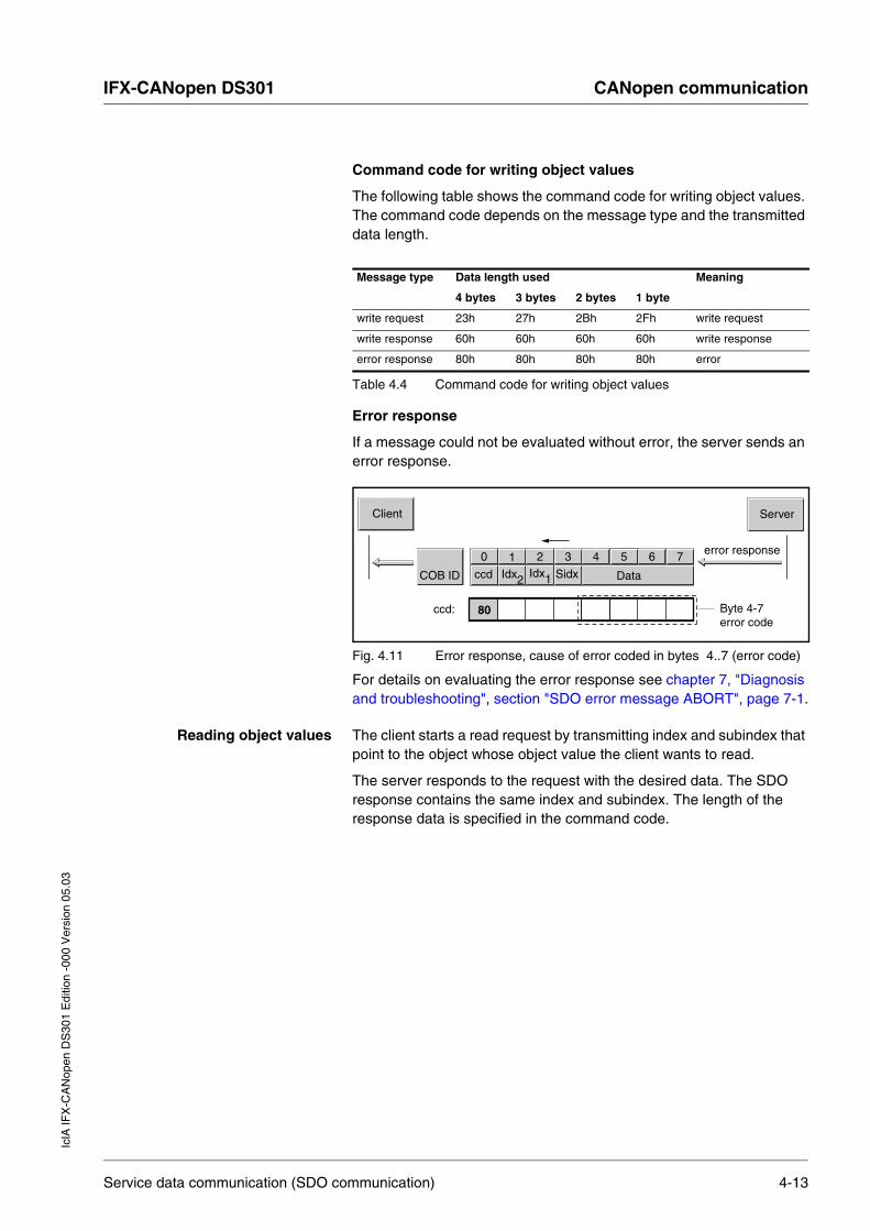
Error response
If a message could not be evaluated without error, the server sends an error response.
Fig. 4.11 Error response, cause of error coded in bytes 4..7 (error code)
For details on evaluating the error response see chapter 7, "Diagnosis and troubleshooting", section "SDO error message ABORT", page 7-1.
Reading object values The client starts a read request by transmitting index and subindex that point to the object whose object value the client wants to read.
The server responds to the request with the desired data. The SDO response contains the same index and subindex. The length of the response data is specified in the command code.
Message type Data length used Meaning
4 bytes 3 bytes 2 bytes 1 byte
write request 23h 27h 2Bh 2Fh write request
write response 60h 60h 60h 60h write response
error response 80h 80h 80h 80h error
Table 4.4 Command code for writing object values
Client Server
1 2 3 4 5 6 70
COB ID ccd Idx2 Idx1 Sidx Data
error response
80ccd: Byte 4-7error code
Service data communication (SDO communication) 4-13

CANopen communication IFX-CANopen DS301
IclA
IFX
-CA
Nop
en D
S30
1 E
ditio
n -0
00 V
ersi
on 0
5.03
Fig. 4.12 Reading parameter value
(1) Struck-through bytes are not used; their contents are not defined.
Command code for reading object values
The following table shows the command code for reading an object value. It depends on the message type and the transmitted data length.
Error response
If a message could not be evaluated without error, the server sends an error response.
For details on evaluating the error response see chapter 7, "Diagnosis and troubleshooting", section "SDO error message ABORT", page 7-1.
Message type Data length used Meaning
4 bytes 3 bytes 2 bytes 1 byte
read request 40h 40h 40h 40h read request
read response 43h 47h 4Bh 4Fh read response
error response 80h 80h 80h 80h error response
Table 4.5 Command code for reading object values
1
Client Server
1 2 3 4 5 6 70
COB ID ccd Idx2 Idx1 Sidx Data
1 2 3 4 5 6 70
COB ID ccd Idx2 Idx1 Sidx Data
Data
Data
Data
D.
read request
read response
43h
47h
4Bh
4Fh
40hccd=
ccd=
ccd=
ccd=
ccd=
4-14 Service data communication (SDO communication)

IFX-CANopen DS301 CANopen communicationIc
lA IF
X-C
AN
open
DS
301
Edi
tion
-000
Ver
sion
05.
03
4.3 Process data communication (PDO communication)
This chapter describes the information flow from the point of view of the compact drive in compliance with the CiA standard DS301. The "receive" label therefore means a data flow from the master to the compact drive, while "transmit" means a data flow from the compact drive to the master.
Process Data Objects (PDO) are used for real-time data exchange of process data such as actual and setpoint position or the operating state of the compact drive. The transmission can be executed very fast, because it is sent without additional administration data and does not require a response from the recipient.
A PDO always is available for sending and receiving a PDO message:
• The T_PDO for sending PDO messages (T: transmit).
• The R_PDO for receiving PDO messages (R: receive).
4.3.1 PDO data exchange
Fig. 4.13 PDO data exchange
Data exchange with PDOs conforms to the producer-consumer relationship and can be triggered in three ways:
• synchronised
• event-driven, asynchronous
• request by a consumer, asynchronous
PDO ConsumerR_PDO
PDO ConsumerR_PDO
R_PDOPDO Consumer
T_PDOPDO Producer
COB ID Data
CAN
Process data communication (PDO communication) 4-15

CANopen communication IFX-CANopen DS301
IclA
IFX
-CA
Nop
en D
S30
1 E
ditio
n -0
00 V
ersi
on 0
5.03
The object SYNC controls the synchronised data processing. Synchronous PDO messages are transmitted immediately like the remaining PDO messages, but only evaluated with the next SYNC object. For example, multiple compact drives can be started simultaneously by synchnronised data exchange.
PDO messages that are called on request by a consumer or are event-driven are evaluated immediately by the network device. An emergency hold information is transmitted asynchronously so the compact drive can execute an immediate emergency stop.
The transmission type can be configured separately for every PDO via the subindex 02h (transmission type).
Triggering message transmissions (trigger modes)
CANopen offers multiple options for transmitting the process data:
Event Driven
The "event" is a modification to the PDO data. The data are sent immediately in this mode after a modification. Note as an example that during a positioning the actual position is continuously changing and that as a result a very large number of PDOs is sent. A large number of PDOs in such circumstances can be prevented by two methods:
• A) An "inhibit timer" (object 1803h subindex 3) can be configured. The PDO will then only be transmitted after expiry of the inhibit period.
• B) The check for modifications (=event) can be restricted with a bit mask. See the "Bit mask for T_PDO4" section below for a description.
Another option for "generating" an event is to activate an event timer (object 1803h subindex 5). This counter is activated by entering a value unequal to zero. The counter sequence also represents an event, i.e. the PDO is transmitted on a value change or counter event.
Synchronised
A PDO is transmitted in relation to a SYNC object in this type of transmission. There is a detailed description in chapter 4.5, "Synchronisation", page 4-30.
4-16 Process data communication (PDO communication)

IFX-CANopen DS301 CANopen communicationIc
lA IF
X-C
AN
open
DS
301
Edi
tion
-000
Ver
sion
05.
03
Remotely requested
Transmission of an asynchronous PDO is triggered by reception of an external request. Such a remote request is displayed by a special bit in the CAN transmission frame and has the same COB-ID (communication object identifier) as the requested communications object.
There is an overview of the various transmission types in the object directory with the PDO parameters.
Bit mask for T_PDO4 A bit mask over all bits in the T_PDO4 can be defined via the CAN.pdo4msk1 (30:9) and CAN.pdo4msk2 (30:10) objects. All bit positions that contain a zero are then no longer taken into account during checking for a modification (=event). For example, this enables only modifications to the driveStat information to be taken into account.
Name Idx:Sub dec. (hex.)
Meaning Bit assignment
Data type Value range (dec.)
Unit Default (dec.)
R/W/rem. Info
CAN.pdo4msk130:9 (1E:09h)
32-bit mask for process data modification part 132-bit mask for event-driven PDO4:
This value allows bytes 1..4 to be unmasked. With event-driven transmission a message is sent at every modification to the T-PDO data. Message transmission can specified more precisely or restricted with this mask. Modifications for event-driven transmission are ignored at all bit positions at which the mask contains a 0.
Exact assignment:Bit 31..24: x_end x_err x_infoBit 23..16: warn Sig_SR FltSig cosBit 15..8: modeStatBit 7..0: ioSignals
The default value 4294967295 corresponds to 0xFFFFFFFF.
UINT32 - 4294967295
R/W/-
CAN.pdo4msk230:10 (1E:0Ah)
32-bit mask for process data modification part 232-bit mask for event-driven PDO4:Mask for bytes 5..8.For description see object pdo4msk1.
UINT32 - 0
R/W/-
Table 4.6 Parameters for the CAN bus
Process data communication (PDO communication) 4-17
CANopen communication IFX-CANopen DS301
IclA
IFX
-CA
Nop
en D
S30
1 E
ditio
n -0
00 V
ersi
on 0
5.03
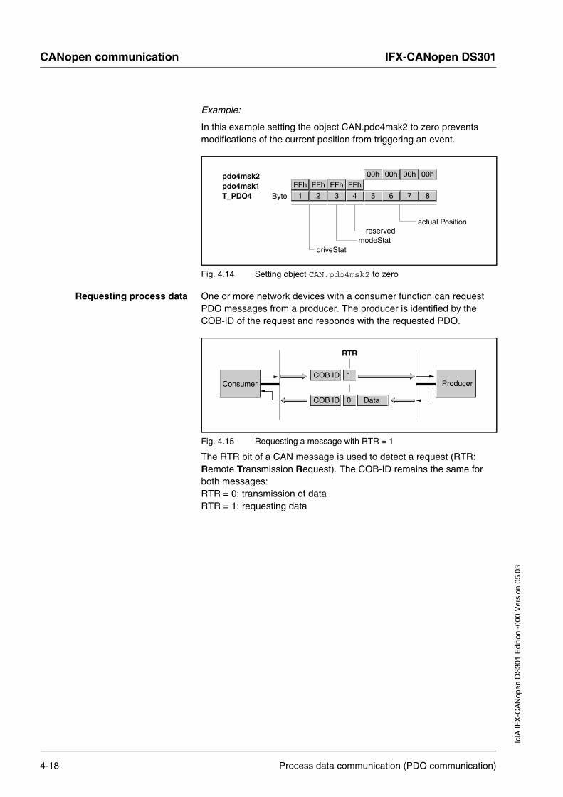
Example:
In this example setting the object CAN.pdo4msk2 to zero prevents modifications of the current position from triggering an event.
Fig. 4.14 Setting object CAN.pdo4msk2 to zero
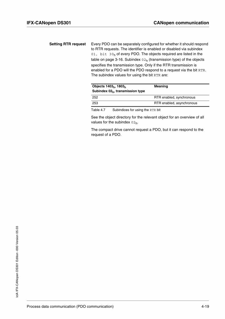
Requesting process data One or more network devices with a consumer function can request PDO messages from a producer. The producer is identified by the COB-ID of the request and responds with the requested PDO.
Fig. 4.15 Requesting a message with RTR = 1
The RTR bit of a CAN message is used to detect a request (RTR: Remote Transmission Request). The COB-ID remains the same for both messages: RTR = 0: transmission of data RTR = 1: requesting data
actual Positionreserved
modeStatdriveStat
21 43 65 87FFhFFh FFhFFh
00h00h 00h00h
ByteT_PDO4pdo4msk1pdo4msk2
RTR
Data
ProducerConsumer
COB ID 0
COB ID 1
4-18 Process data communication (PDO communication)
IFX-CANopen DS301 CANopen communicationIc
lA IF
X-C
AN
open
DS
301
Edi
tion
-000
Ver
sion
05.
03
Setting RTR request Every PDO can be separately configured for whether it should respond to RTR requests. The identifier is enabled or disabled via subindex 01, bit 30h of every PDO. The objects required are listed in the
table on page 3-16. Subindex 02h (transmission type) of the objects
specifies the transmission type. Only if the RTR transmission is enabled for a PDO will the PDO respond to a request via the bit RTR. The subindex values for using the bit RTR are:
See the object directory for the relevant object for an overview of all values for the subindex 02h.
The compact drive cannot request a PDO, but it can respond to the request of a PDO.
Objects 1403h, 1803h Subindex 02h, transmission type
Meaning
252 RTR enabled, synchronous
253 RTR enabled, asynchronous
Table 4.7 Subindices for using the RTR bit
Process data communication (PDO communication) 4-19
CANopen communication IFX-CANopen DS301
IclA
IFX
-CA
Nop
en D
S30
1 E
ditio
n -0
00 V
ersi
on 0
5.03
4.3.2 Dynamic and static PDO mapping
Dynamic PDO mapping The settings for PDO mapping are defined in an assigned communications object for every PDO. If the settings for PDO mapping for a PDO can be modified, this is referred to as dynamic PDO mapping for the PDO. Dynamic PDO mapping allows flexible combination of different process data during operation.
Static PDO mapping In static PDO mapping all objects are mapped in accordance with a fixed, non-modifiable setting in the relevant PDO.
Properties of the IclA IFx compact drive
The IclA IFx compact drive supports 2 PDOs, the communications objects T_PDO4 and R_PDO4. PDO4 is enabled for both by default.
These PDOs are statically mapped and so cannot be configured but only read. The indices for the permanently entered objects can be read from the PDO mapping object range:
• object 1403h: receive PDO4 communication parameter
• object 1603h: receive PDO4 mapping
• object 1803h: transmit PDO4 communication parameter
• objekt 1A03h: transmit PDO4 mapping
4-20 Process data communication (PDO communication)

IFX-CANopen DS301 CANopen communicationIc
lA IF
X-C
AN
open
DS
301
Edi
tion
-000
Ver
sion
05.
03
4.3.3 Receive PDO R_PDO4 (master → compact drive)
The master device can execute the following actions via the PDO4 channel to the compact drive:
• control of the compact drive status machine
– enable or disable power amplifier
– trigger and reset Quick-Stop
– resetting errors
• enable operating modes
– point-to-point mode (absolute and relative)
– speed mode
– reference movement
– dimension setting
• transfer setpoint values
– setpoint position
– setpoint speed
– type of reference movement
Structure of the R_PDO4:
Fig. 4.16 Structure of the R_PDO4
Ref32 -> reference 32 bits - e.g. positionRef16 -> reference 16 bits - e.g. velocity
modeCtrldriveCtrl
21 43 65 87Byte
67 45 23 0100 QR0 QSFR DIEN
DisableEnable
QuickstopFault Reset
Quickstop Release
driveCtrl - 8 Bits
Bit
67 45 23 01MT ACTION 0 MODE
Requested Mode
Action within Mode
Mode Toggle
modeCtrl - 8 Bits
Bit
Process data communication (PDO communication) 4-21

CANopen communication IFX-CANopen DS301
IclA
IFX
-CA
Nop
en D
S30
1 E
ditio
n -0
00 V
ersi
on 0
5.03
Status machine – driveCtrl
The status machine is controlled via PDO4 or the SDO object driveCtrl, 28:1, in each case via bits 0..4.
In PDO mode these bits operate slope selectively, i.e. the relevant function is triggered with a "0 → 1" slope.
In the event of access by SDO a write access with a set bit value is sufficient; i.e. a slope change is not required.
The value "0" is a special case: if all bits 0..7 are zero during transmission, the compact drive interprets this as a disable command and the power amplifier is disabled. This is applicable both for PDO and SDO accesses.
Fault processing
If requests for controlling the status machine by the compact drive cannot be implemented, the compact drive ignores these requests. There is no error response.
Operating modes – modeCtrl
In PDO mode the operating modes are controlled via the modeCtrl object.
The master must enter the following value to trigger an operating mode or modify setpoint values:
• setpoint values in the fields "Ref16" and "Ref32"
• select mode with modeCtrl, bits 0..2 (MODE)
• select action for this mode with modeCtrl, bits 4..6 (ACTION)
• toggle modeCtrl, bit 7 (MT)
Controlling the status machine
PDO4 Bits 0...4
SDO object driveCtrl, 28:1 Bits 0...4
Bit 0: disable amplifier Process is run at 0 → 1 slope Processing is run at write access if bit value =1Bit 1: enable amplifier
Bit 2: Quick-Stop
Bit 3: Fault Reset
Bit 4: Quick-Stop release
Table 4.8 Controlling the status machine
4-22 Process data communication (PDO communication)

IFX-CANopen DS301 CANopen communicationIc
lA IF
X-C
AN
open
DS
301
Edi
tion
-000
Ver
sion
05.
03
Table 4.1, page 4-1 shows the possible modes and the associated setpoint values
Setpoint positions are entered in increments, setpoint speeds in rpm.
In the event of simultaneous transmission of operating mode, setpoint position and setpoint speed in a PDO data consistency must be retained. As a result the compact drive only evaluates the operating mode data if bit 7 has been toggled. Toggling means that since the last transmission a "0 → 1" or a "1 → 0" slope change was detected.
Bit 7 is mirrored in the response PDO4 by the compact drive, so a synchronized operation is possible via the PDO4.
For more information see section 4.3.4, "Send PDO T_PDO4 (compact drive → master)", page 4-24.
Fault processing
Requests for the operating mode are triggered by toggling bit 7. If the requests cannot be implemented, the compact drive executes an error response as described in the section Transmit PDO4 error processing.
For more information see section 4.3.4, "Send PDO T_PDO4 (compact drive → master)", page 4-24.
Mode bits 0..2
Action bits 4..6
modeCtrl* bits 0..6
Description Corres-ponds to object**
Setpoint value Ref16
Setpoint value Ref32
2 (Homing) 0 02h Dimension setting 40:3 - Dimension setting position
1 12h Reference movement 40:1 Type (as obj. 40:1) -
3 (PTP) 0 03h Absolute positioning 35:1 Setpoint speed Setpoint position
1 13h Relative positioning 35:3 Setpoint speed Setpoint position
2 23h Continuation of positioning 35:4 Setpoint speed -
4 (VEL) 0 04h Speed mode 36:1 Setpoint speed -
* Column corresponds to the value to be entered in byte modeCtrl, but without ModeToggle (bit 7).
** Column shows Index:Subindex (decimal) of the corresponding operating modes, which are described in more detail in the device documentation.
Table 4.9 Configure operating modes via modeCtrl
Process data communication (PDO communication) 4-23

CANopen communication IFX-CANopen DS301
IclA
IFX
-CA
Nop
en D
S30
1 E
ditio
n -0
00 V
ersi
on 0
5.03
4.3.4 Send PDO T_PDO4 (compact drive → master)
In the default settings of the compact drive the send PDO is sent asynchronously event-driven; the "inhibit time" setting for the time is possible.
The compact drive supplies the following information to the master over the PDO4 channel:
• status of status machine
• errors and warnings
• active operating mode
• status of active operating mode
– mode ended
– fault has occurred
– setpoint speed or setpoint position reached
– actual position
• compact drive referenced
• acknowledgment of operating mode requests
• status of the 24V inputs or outputs
Structure of the T_PDO4:
Fig. 4.17 Structure of the T_PDO4
actual position (pact), 32 bitsioStat, 8 bits
modeStat, 8 bitsdriveStat, 16 bits
21 43 65 87Byte
67 45MEMT 0ref_ok
23 010 mode
actual operation mode
drive referenced
Mode ToggleMode Error
modeStat
Bit
driveStat
Bitx err x_end x_info 0 0 0 0 0 warn Sig_SR FltSig cos015 14 13 12 --- 8 7 6 5 3 --- 04
4-24 Process data communication (PDO communication)

IFX-CANopen DS301 CANopen communicationIc
lA IF
X-C
AN
open
DS
301
Edi
tion
-000
Ver
sion
05.
03
Status word driveStat The information in the status word driveStat corresponds to bits 0..15 of the object Status.driveStat, 28:2.
Contents of information:
• status of status machine
• warning and error bits
• status of the current axis mode.
Mode modeStat This field corresponds to bits 0..2 of the object Status.xMode_act. Bits 6 and 7 are additional information that can be used to run a synchronised mode control via the PDO.
Process data communication (PDO communication) 4-25

CANopen communication IFX-CANopen DS301
IclA
IFX
-CA
Nop
en D
S30
1 E
ditio
n -0
00 V
ersi
on 0
5.03
The field contains the following information:
Synchronised processing can be run with R_PDO4, bit 7 (ModeToggle – MTreq) and T_PDO4, bit 6 and 7. Synchronised processing means that the master device waits for responses from the compact drive and responds to them.
Example
Positioning with concluding check that it was conducted correctly.
Bit Name Description
0...2 mode Current configured mode as with R_PDO4
5 ref_ok Set when the compact drive has been successfully referenced by reference movement or setting dimensions.
6 ME, ModeError Set if a request by the master device over R_PDO4 was rejected by the compact drive.
7 MT, ModeToggle Mirrors bit 7 (Mode Toggle) by R_PDO4
Table 4.10 Mode modeStat
Master Compact drive
Setpoint values for positioning in the fields "Ref16" and "Ref32" - set the desired mode in the mode field - toggle bit 7
R_PDO4 ⇒ MTreq ≠ MTstat ⇒
If MT is toggled, then - import values - start desired mode - update status: x_end = 0 - MT mirrored by R_PDO to T_PDO
T_PDO4 ⇐MTstat = MTreq
x_end = 0⇐
If MTstat = MTreq then status is current: - check ME: 1 ⇒ request failed - to x_end = 1 wait: 1 ⇒ end of positioning
Positioning finished: x_end = 1
T_PDO4 ⇐MTstat = MTreq
x_end = 1⇐
Table 4.11 Example: Positioning with concluding check
4-26 Process data communication (PDO communication)

IFX-CANopen DS301 CANopen communicationIc
lA IF
X-C
AN
open
DS
301
Edi
tion
-000
Ver
sion
05.
03
Special case much shorter positioning
In the case of a very short positioning, the compact drive may have already reached the setpoint position when the status is returned to the master device via the T_PDO4. In this case R_PDO4, bit 7 is equal to T_PDO4, bit 7 and bit x_end = 1 is already set. Therefore, the case x_end = 0 does not apply to the master device. If no error has occurred, the positioning has still been correctly carried out.
Fault processing If the master device toggles bit 7, this is considered a request to the compact drive to start a mode or to modify data of the current mode. If the compact drive cannot process the request, it signals this to the master by the following actions:
• sends a EMCY with the corresponding error code
• sets T_PDO4, bit 6 (ModeError) This bit remains set until T_PDO4, bit 7 (ModeToggle) is toggled again.The master device can read the corresponding error code by an SDO read access to object CAN.modeError, 30:11.
• continuation of the current operating mode
The current mode is thus not influenced and there is no status change.
The reasons for a failed mode request can include the following:
• setpoint values outside the value range
• mode cannot be switched during processing
• invalid mode requested
• status machine not in status 6 (Operation Enable)
Process data communication (PDO communication) 4-27

CANopen communication IFX-CANopen DS301
IclA
IFX
-CA
Nop
en D
S30
1 E
ditio
n -0
00 V
ersi
on 0
5.03
4.4 Emergency service
The emergency service reports internal device error over the CAN bus. The error message is sent to all network devices in accordance with the consumer-producer relationship with an EMCY object.
Fig. 4.18 Error message with the EMCY object
EMCY message Causes of an EMCY message are:
• asynchronous error, error code = 1000h If an internal unit error occurs, the compact drive switches to error mode in accordance with the unit status machine. The compact drive sends an EMCY message with error register and error code at the same time.
• PDO4 error with operating mode controller, error code = 8200h If the request for an operating mode by PDO4 fails, the compact drive also sends an EMCY message.
• CAN communication error, error code = 8100h
Fig. 4.19 EMCY message
(1) (1) Byte 0, 1("error code"): CANopen error code This value in the compact drive is 1000h, 8200h or 8100h
depending on the cause of the error.
(2) Byte 2 ("error register"): Error register The value is also saved in the object Error register, 1001h.
EMCY-Consumer EMCY-Consumer
EMCY-Producer
COB ID
CAN
EMCY-Consumer
Data
Manufacturer specific error field
Error register
Error code Error Field
COB ID (80h+ node ID)
1 2 3 4 5 6 710
000 01 00 01 000C 00
81
4 50C 01
01 0C
4-28 Emergency service

IFX-CANopen DS301 CANopen communicationIc
lA IF
X-C
AN
open
DS
301
Edi
tion
-000
Ver
sion
05.
03
(3) Byte 3-7 (Manufacturer Specific Error Field): Manufacturer-specific errorByte 3 and bytes 6,7 are always 0.A manufacturer-specific number is stored in bytes 4,5. A list of error numbers can found in chapter 7.2 "Error number" of the controller manual.
COB-ID The COB-ID calculates the following from the node address for every network device that supports an EMCY object:
COB-ID = function code of the object EMCY, 80h + node-ID
Emergency service 4-29
CANopen communication IFX-CANopen DS301
IclA
IFX
-CA
Nop
en D
S30
1 E
ditio
n -0
00 V
ersi
on 0
5.03
4.5 Synchronisation
The synchronisation object SYNC controls synchronous message exchange between network devices, e.g. to enable multiple compact drives to be started.
The data exchange conforms to the producer-consumer relationship. The synchronisation object SYNC is sent from one network device to all network devices and can be evaluated by all network devices that support synchronous PDOs.
Fig. 4.20 SYNC message
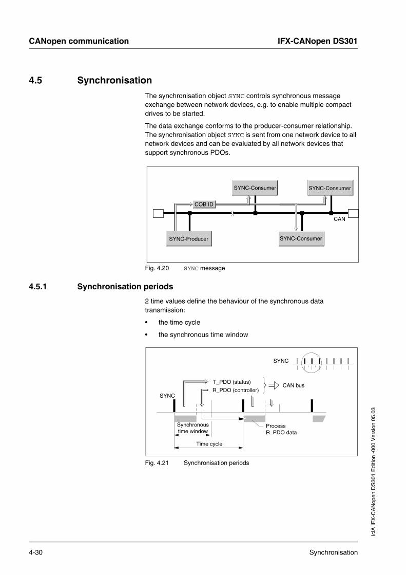
4.5.1 Synchronisation periods
2 time values define the behaviour of the synchronous data transmission:
• the time cycle
• the synchronous time window
Fig. 4.21 Synchronisation periods
SYNC-Consumer SYNC-Consumer
SYNC-Producer
COB ID
CAN
SYNC-Consumer
SYNC
SYNC
Time cycle
Synchronoustime window
T_PDO (status)
R_PDO (controller)
ProcessR_PDO data
CAN bus
4-30 Synchronisation

IFX-CANopen DS301 CANopen communicationIc
lA IF
X-C
AN
open
DS
301
Edi
tion
-000
Ver
sion
05.
03
The time cycle shows the time gap between two 2 SYNC messages and is configured with the Communication Cycle Period, 1006h
object.
The synchronous time window apecifies the time gap in which synchronous PDO messages must be received and sent. The time window is defined by the object Synchronous Window Length, 1007h.
4.5.2 Synchronous data transmission
From the point of view of a SYNC receiver, in one time window the status data are sent first in a T_PDO, then new control data are received via an R_PDO. However, the control data are only processed when the next SYNC message is received. The synchronisation object SYNC itself does not carry data.
Cyclic/acyclic Synchronous data transmission can be cyclic or acyclic.
You can specify whether a PDO acts in a cyclic or acyclic manner in the subindex transmission type, 02h of the PDO parameter.
Fig. 4.22 Cyclic and acyclic transmission
In cyclic transmission PDO messages are exchanged continuously in a specified cycle, e.g. with every SYNC message.
If a synchronous PDO message is transmitted acyclically, the PDO message can be sent or received at any time. However, the PDO message will only be valid with the next SYNC message.
COB-ID To ensure fast transmission of the SYNC synchronisation object, it is transmitted unconfirmed and at high priority. The COB-ID of the SYNC synchronisation object is always 128 (80h) for the compact drive.
T_PDO: cyclic
T_PDO: acyclic
SYNC
Synchronisation 4-31

CANopen communication IFX-CANopen DS301
IclA
IFX
-CA
Nop
en D
S30
1 E
ditio
n -0
00 V
ersi
on 0
5.03
4.6 Network management objects
Network management (NMT) is a component of the CANopen communication profile.
NMT is used for the following tasks:
• connection monitoring
– network initialisation
– network monitoring
• monitoring network devices
– initialisation
– starting
– stopping
– status
NMT is implemented as a master-slave relationship. The NMT master device addresses individual NMT slave devices by their node address.
A message with node address "0" is addressed to all NMT slaves simultaneously.
Fig. 4.23 NMT over the master-slave relationship
The compact drive can only take on the role of an NMT slave.
NMT-Slave
NMT-Slave
NMT-Slave
NMT-Slave
NMT-Slave
NMT-Master
CAN
COB ID Data
4-32 Network management objects

IFX-CANopen DS301 CANopen communicationIc
lA IF
X-C
AN
open
DS
301
Edi
tion
-000
Ver
sion
05.
03
4.6.1 NMT services for controlling the compact drive
NMT status machine The NMT status machine describes the behaviour of a compact drive in network operation:
• initialisation
• operating states
Fig. 4.24 NMT status machine
A Start Remote Node
B Stop Remote Node
C Enter Pre-Operational
D Reset Node
E Reset Communication
Initialising compact drive After switching on the power supply, the compact drive automatically runs an initialisation phase that prepares it for CANopen operation.
During the initialisation phase the compact drive loads the non-volatile object data into RAM from the EEPROM.
At the end of the initialisation phase the compact drive switches to the Pre-operational operating status and sends the Boot Up message.
From this point an NMT master device can control the mode behaviour of a compact drive in the network with the five NMT services.
Operational
Pre-Operational
Stopped
ResetApplication
ResetCommunication
Initialization
Power on
CA
DE
BNMT
SDO, EMCY NMT
PDO, SDO, SYNCEMCY, NMT
Network management objects 4-33

CANopen communication IFX-CANopen DS301
IclA
IFX
-CA
Nop
en D
S30
1 E
ditio
n -0
00 V
ersi
on 0
5.03
NMT services
Transmission priority The NMT services for controlling the compact drive are transmitted as messages not requiring confirmation with the COB-ID = 0. By default they receive top priority on the CAN bus.
Data frame The data frame of an NMT messages consists of two bytes.
Fig. 4.25 Data frame of an NMT message
Byte 0 (Command Specifier) specifies the NMT service in use.
NMT service Transition Meaning
Start Remote Mode A Switch to Operational operating status. Start standard network operation to all network devices.
Stop Remote Node B Switch to Stopped operating status stop compact drive communication. If connection monitoring is active, it remains switched on.
Enter Pre-Operational C Switch to Pre-Operational operating status. All communications objects can be set except for PDOs. The Pre-Operational operating status can be used for configuration by SDOs: - PDO mapping - start synchronisation - start connection monitoring
Reset Node D Switch to Reset Application operating status. Load stored device profile data and switch automatically to Pre-Operational via Reset Communication operating status
Reset Communication
E Switch to Reset Communication operating status. Load stored communication profile data and switch automatically to Pre-Operational operating status.
Table 4.12 NMT services for controlling the compact drive
NMT-Slave
NMT-Slave
NMT-Slave
NMT-Master 00010
Command specifierCOB ID
node ID
Byte 0 1
4-34 Network management objects
IFX-CANopen DS301 CANopen communicationIc
lA IF
X-C
AN
open
DS
301
Edi
tion
-000
Ver
sion
05.
03
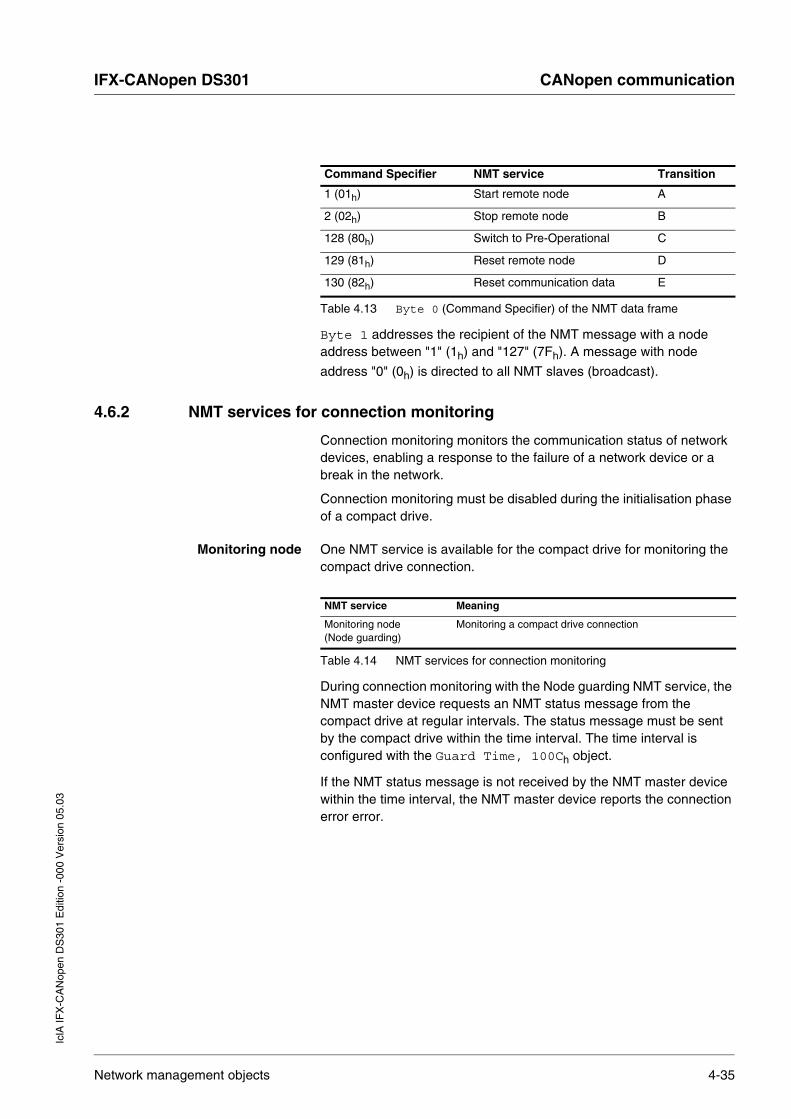
Byte 1 addresses the recipient of the NMT message with a node address between "1" (1h) and "127" (7Fh). A message with node
address "0" (0h) is directed to all NMT slaves (broadcast).
4.6.2 NMT services for connection monitoring
Connection monitoring monitors the communication status of network devices, enabling a response to the failure of a network device or a break in the network.
Connection monitoring must be disabled during the initialisation phase of a compact drive.
Monitoring node One NMT service is available for the compact drive for monitoring the compact drive connection.
During connection monitoring with the Node guarding NMT service, the NMT master device requests an NMT status message from the compact drive at regular intervals. The status message must be sent by the compact drive within the time interval. The time interval is configured with the Guard Time, 100Ch object.
If the NMT status message is not received by the NMT master device within the time interval, the NMT master device reports the connection error error.
Command Specifier NMT service Transition
1 (01h) Start remote node A
2 (02h) Stop remote node B
128 (80h) Switch to Pre-Operational C
129 (81h) Reset remote node D
130 (82h) Reset communication data E
Table 4.13 Byte 0 (Command Specifier) of the NMT data frame
NMT service Meaning
Monitoring node (Node guarding)
Monitoring a compact drive connection
Table 4.14 NMT services for connection monitoring
Network management objects 4-35
CANopen communication IFX-CANopen DS301
IclA
IFX
-CA
Nop
en D
S30
1 E
ditio
n -0
00 V
ersi
on 0
5.03
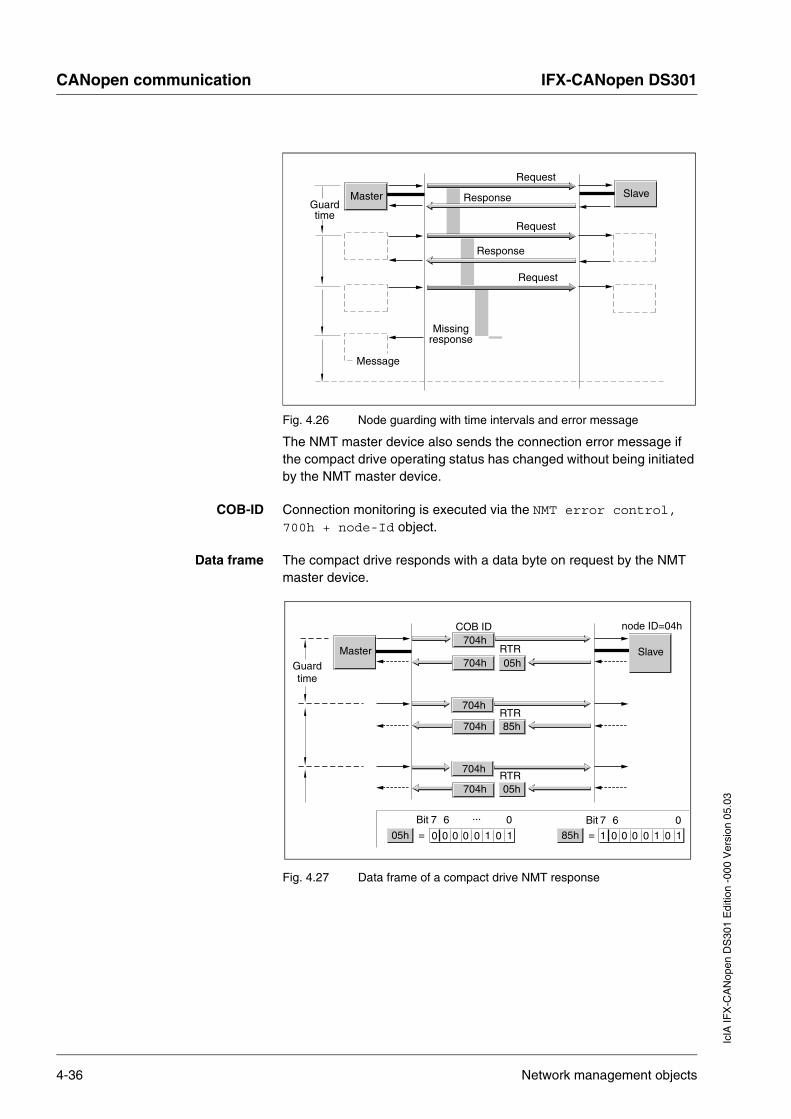
Fig. 4.26 Node guarding with time intervals and error message
The NMT master device also sends the connection error message if the compact drive operating status has changed without being initiated by the NMT master device.
COB-ID Connection monitoring is executed via the NMT error control, 700h + node-Id object.
Data frame The compact drive responds with a data byte on request by the NMT master device.
Fig. 4.27 Data frame of a compact drive NMT response
SlaveMasterGuardtime
Request
Response
Response
Request
Request
Missingresponse
Message
SlaveMaster05h
05h
COB ID
RTR
RTR
RTR
704h
704h
node ID=04h
704h
704h 85h
704h
704h 05h
Guardtime
Bit 7 6 ... 0
00 0 0 0 0 11
Bit 7 6 085h 0 0 0 0 01 11= =
4-36 Network management objects

IFX-CANopen DS301 CANopen communicationIc
lA IF
X-C
AN
open
DS
301
Edi
tion
-000
Ver
sion
05.
03
Bits 0 … 6
The bits 0.. 6 contain the current operating status of the compact drive:
• value = 4 (04h)
operating status Stopped
• value = 5 (05h)
operating status Operational
• value = 127 (7Fh)
operating status Pre-Operational
Bit 7
Bit 7 switches between "0" and "1" on every response. The NMT master device detects when a response has been seen multiple times by bit 7. The NMT master device only considers the first response.
The first request when starting connection monitoring begins with bit 7 = 0.
The status of bit 7 is reset as soon as the compact drive runs through the NMT operating status reset communication.
Connection monitoring continues in NMT operating status stopped.
Boot Up message Communication profile DS301, version 4.0 defines an additional task for the NMT services: sending a boot-up message.
A network device informs all other network devices that it is ready for operation with a boot-up message.
A boot-up message consists of the COB-ID of the NMT Error Control object and is sent without data. Standard setting of the COB-ID is 1792 (700h) + node-ID
Network management objects 4-37

CANopen communication IFX-CANopen DS301
IclA
IFX
-CA
Nop
en D
S30
1 E
ditio
n -0
00 V
ersi
on 0
5.03
4-38 Network management objects
IFX-CANopen DS301 Installation and setupIc
lA IF
X-C
AN
open
DS
301
Edi
tion
-000
Ver
sion
05.
03
5 Installation and setup
5.1 Installation
For information about installation, refer to the controller manual, "Installation" chapter.
Compact drives with DIP switches
Before installing the compact drive in the system, you must set the network address and the baud rate via the DIP switches in the plug housing.
For information about DIP switch settings, refer to the the controller manual, "Installation" chapter.
5.2 Commissioning field bus connection
5.2.1 Starting field bus operation
Configuration with SyCon Instructions for using the Hilsch SyCon configuration software:
In the Node Configuration do not change the Unit Profile setting (value= 0)!
If this value is changed, communication with the drive will no longer function. However, the setting cannot be reset to the original status.
Proceed as follows to restore communication with the IclA IFX drive:
� Click Node BootUp button in the Node Configuration dialog.
� Click Check Node Type and Profile in the Node BootUp dialog to bypass this step.
Testing field bus operation After correct configuration of the transmission data test the field bus operation.
This requires installation of a CAN configuration tool that displays CAN messages. The acknowledgment from the drive is captured by a boot-up message:
� Switch the drive power supply off and on again.
� Observe the network messages shortly after switching on the unit. The positioning controller sends a 1-byte-long boot-up message after initialization of the bus: 128 (80h)+node-Id.
With node address factory-set to 127 (7Fh) the boot-up message 255
(FFh) is sent over the bus. The drive can then be put into operation via
NMT services.
Installation 5-1

Installation and setup IFX-CANopen DS301
IclA
IFX
-CA
Nop
en D
S30
1 E
ditio
n -0
00 V
ersi
on 0
5.03
5.2.2 Troubleshooting
If the compact drive does not respond, check the following settings:
� Has the compact drive been started and the master device switched on?
� Are the cable connections mechanically and electrically sound?
� Is the address on the compact drive correctly set? Check the DIP switch and HEX switch settings. The settings are described in the manual for the unit. Compact drives with DIP switches are set by default to the CAN address "127" (7Fh) and the baud rate "125
kBit/s".
� Are the same baud rate and the same interface parameters set on the master device and compact drive?
If the compact drive still does not respond:
� Open the plug cover.
� If the compact drive is functioning correctly with the power amplifier off, the LED in the plug housing flashes constantly at 0.5 Hz (1 second on, 1 second off). If this is not the case, the compact drive has an operational error. See the controller manual for information on causes of errors and troubleshooting.
� Compare the LED display with the information in the following table.
Refer to the controller manual for further information on the causes of errors and troubleshooting.
Error Error class Cause of error Troubleshooting
LED off – No power supply. Check power supply and fuses.
LED flashes at 0.5 Hz. (1 s on, 1 s off)
– Firmware works without errors, power amplifier inactive.
Check cable connections. Check DIP switch settings.
LED flashes at 6 Hz. 4 Flash checksum wrong. Reinstall firmware. Replace compact drive.
LED flashes at 10 Hz. Watchdog
4 Hardware error Switch compact drive off and on again. Replace compact drive.
5-2 Commissioning field bus connection
IFX-CANopen DS301 Examples for field bus operationIc
lA IF
X-C
AN
open
DS
301
Edi
tion
-000
Ver
sion
05.
03
6 Examples for field bus operation
6.1 Overview
The program examples show practical applications for network operation of IFx compact drives. There are generally two access methods over the CANopen field bus: SDO (Service Data Objects) and PDO (Process Data Objects).
Using SDO An SDO access is always a write or read access to one single object. The available objects are described in the controller manual and is also summarized there as a table in chapter 9, "Parameters". The use of SDO is described in this chapter with the examples of only a few objects, because this type of communication can be used for all available user objects and is always structured very similarly.
Using PDO PDOs are recommended for positioning mode, because the information here is transferred much more effectively. Various practical examples are given for the application of PDO4, which is supported by the compact drive, and the general procedure is described.
• The PDO from the "master device" to the compact drive is labeled "R_PDO".
• The PDO from the compact drive to the "master device" is labeled "T_PDO".
Structure of the examples When describing the PDOs, note that they are described from the point of view of the compact drive.
The following is shown:
• description of task
• initial conditions
• commands required in transmitted data frame
• response of compact drive in received data frame
• possible limitations on command execution
Overview 6-1

Examples for field bus operation IFX-CANopen DS301
IclA
IFX
-CA
Nop
en D
S30
1 E
ditio
n -0
00 V
ersi
on 0
5.03
You should be aware of the following to be able to reproduce the examples:
• operating concept and functional scope of the compact driveYou will find information on this in the manual.
• field bus protocol and connection to the master controller
• functional scope of the field bus profile
Manual The examples are designed to complement the function descriptions in the manuals. The manual describes the basic functions of the operating modes and functions.
You will also find all parameters regarding the operating modes and functions listed there.
The number format of the parameter values in a field bus command is described in table 9.2, page 9-1 of the controller manual.
6-2 Overview
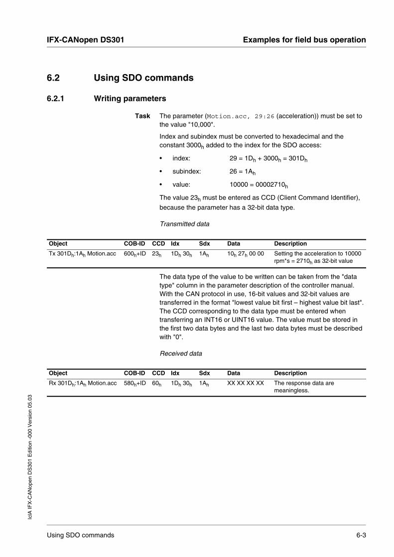
IFX-CANopen DS301 Examples for field bus operationIc
lA IF
X-C
AN
open
DS
301
Edi
tion
-000
Ver
sion
05.
03
6.2 Using SDO commands
6.2.1 Writing parameters
Task The parameter (Motion.acc, 29:26 (acceleration)) must be set to the value "10,000".
Index and subindex must be converted to hexadecimal and the constant 3000h added to the index for the SDO access:
• index: 29 = 1Dh + 3000h = 301Dh
• subindex: 26 = 1Ah
• value: 10000 = 00002710h
The value 23h must be entered as CCD (Client Command Identifier),
because the parameter has a 32-bit data type.
Transmitted data
The data type of the value to be written can be taken from the "data type" column in the parameter description of the controller manual. With the CAN protocol in use, 16-bit values and 32-bit values are transferred in the format "lowest value bit first – highest value bit last". The CCD corresponding to the data type must be entered when transferring an INT16 or UINT16 value. The value must be stored in the first two data bytes and the last two data bytes must be described with "0".
Received data
Object COB-ID CCD Idx Sdx Data Description
Tx 301Dh:1Ah Motion.acc 600h+ID 23h 1Dh 30h 1Ah 10h 27h 00 00 Setting the acceleration to 10000 rpm*s = 2710h as 32-bit value
Object COB-ID CCD Idx Sdx Data Description
Rx 301Dh:1Ah Motion.acc 580h+ID 60h 1Dh 30h 1Ah XX XX XX XX The response data are meaningless.
Using SDO commands 6-3
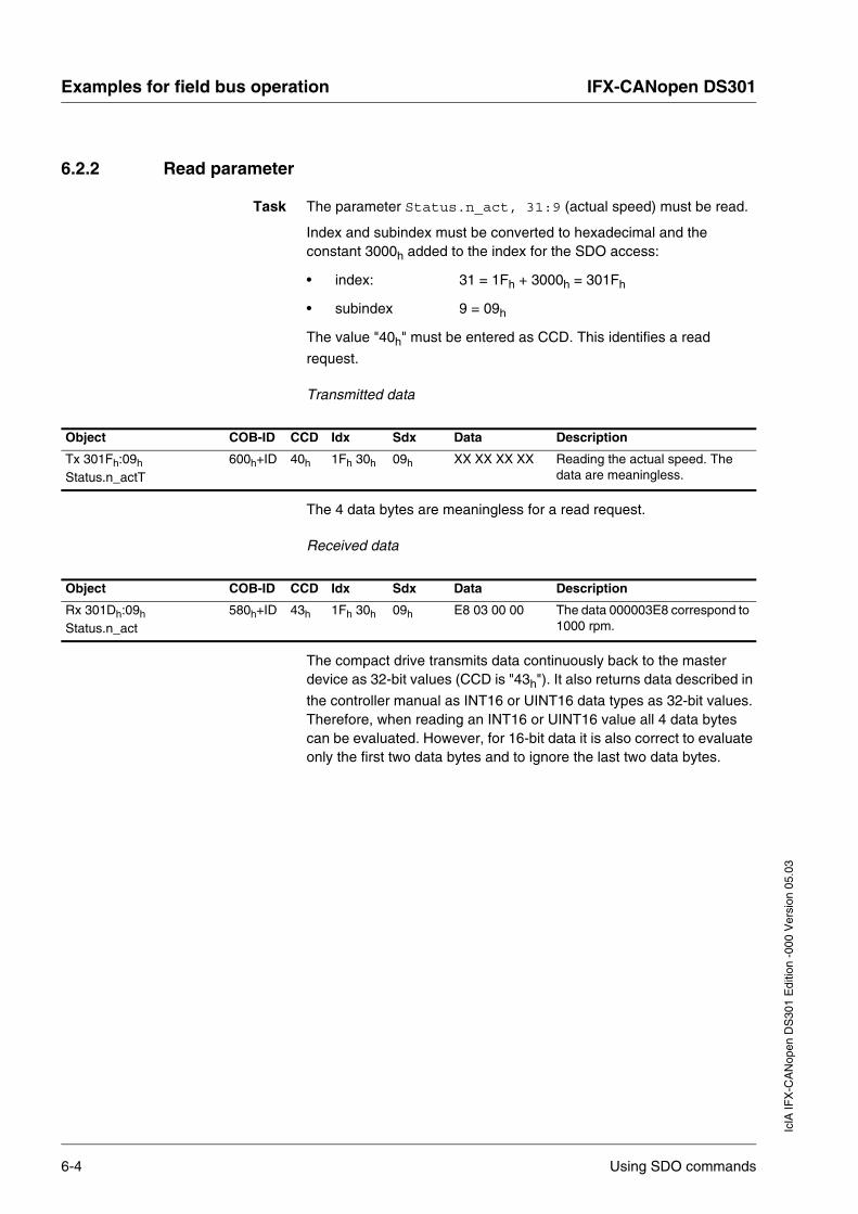
Examples for field bus operation IFX-CANopen DS301
IclA
IFX
-CA
Nop
en D
S30
1 E
ditio
n -0
00 V
ersi
on 0
5.03
6.2.2 Read parameter
Task The parameter Status.n_act, 31:9 (actual speed) must be read.
Index and subindex must be converted to hexadecimal and the constant 3000h added to the index for the SDO access:
• index: 31 = 1Fh + 3000h = 301Fh
• subindex 9 = 09h
The value "40h" must be entered as CCD. This identifies a read
request.
Transmitted data
The 4 data bytes are meaningless for a read request.
Received data
The compact drive transmits data continuously back to the master device as 32-bit values (CCD is "43h"). It also returns data described in
the controller manual as INT16 or UINT16 data types as 32-bit values. Therefore, when reading an INT16 or UINT16 value all 4 data bytes can be evaluated. However, for 16-bit data it is also correct to evaluate only the first two data bytes and to ignore the last two data bytes.
Object COB-ID CCD Idx Sdx Data Description
Tx 301Fh:09h Status.n_actT
600h+ID 40h 1Fh 30h 09h XX XX XX XX Reading the actual speed. The data are meaningless.
Object COB-ID CCD Idx Sdx Data Description
Rx 301Dh:09h Status.n_act
580h+ID 43h 1Fh 30h 09h E8 03 00 00 The data 000003E8 correspond to 1000 rpm.
6-4 Using SDO commands

IFX-CANopen DS301 Examples for field bus operationIc
lA IF
X-C
AN
open
DS
301
Edi
tion
-000
Ver
sion
05.
03
6.2.3 Synchronous errors
If an SDO write or read command fails, the compact drive responds with an error data frame (error response). For example, an error source can be trying to read or write a non-existent object. The transmitted error number shows information on the exact cause.
Receive data with error data frame (error response)
The example shows the response to a write or read request for a non-existent object 40:32.
The error number of a synchronous error message is stored as a UINT16 value and the value "80h" is transferred to the corresponding
CCD (error response). The table of error numbers can be found in chapter 7.2.1, "Synchronous errors".
Object COB-ID CCD Index Sub Data Description
Rx 3028h:20h 580h+ID 80h 28h 30h 20h 00 00 02 06 Error number 06020000h means "object not in object directory"
Using SDO commands 6-5

Examples for field bus operation IFX-CANopen DS301
IclA
IFX
-CA
Nop
en D
S30
1 E
ditio
n -0
00 V
ersi
on 0
5.03
6.3 Changing operating states with PDO4
The compact drive detects different operating states. The different operating states are numbered from 1 to 9. The operating states and the transition conditions are described in more detail in the controller manual, "Operation/Basics" chapter.
Table 6.1, page 6-6 shows the most important operating states:
Requests for switching operating states are transmitted to the compact drive in R_PDO4 in the driveCtrl field. It reports the current operating state back to the master device in T_PDO4, driveStat field.
Table 6.2, page 6-6 shows the bit assignment of the driveCtrl field in the R_PDO4 object:
6.3.1 Switch power amplifier on and off
The power amplifier is switched on by the transition from operating state 4 to 6. To do this R_PDO4 contains the two bits Enable and Disable. One must always be set to "1" and the other to "0".
Operating state
Name Power amplifier
Description
4 Ready To Switch On off passive operating state, motor without power
6 Operation Enable on active operating state, motor under power
7 Quick-Stop Active on error state, power amplifier remains on
9 Fault off error state, power amplifier switched off
Table 6.1 Important operating states
Bit no. Pulse value Meaning
0 01h Disable
1 02h Enable
2 04h Quick-Stop
3 08h FaultReset
4 10h Quick-Stop release
Table 6.2 R_PDO4, driveCtrl, bit assignment
6-6 Changing operating states with PDO4
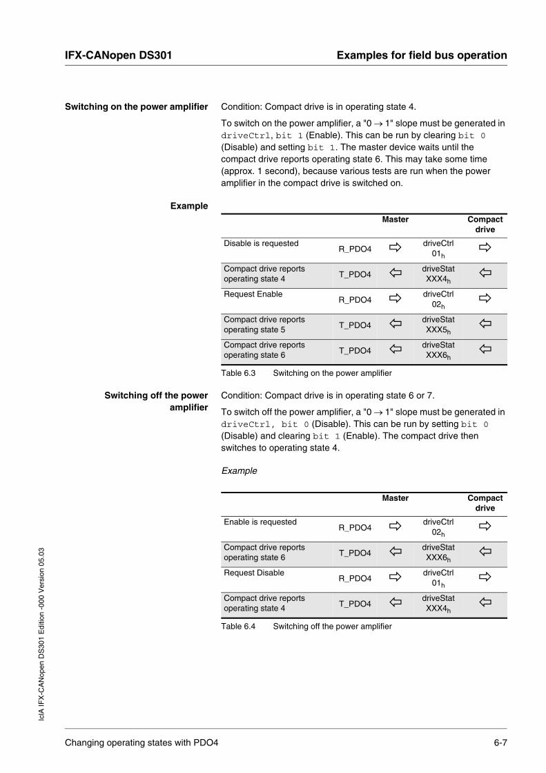
IFX-CANopen DS301 Examples for field bus operationIc
lA IF
X-C
AN
open
DS
301
Edi
tion
-000
Ver
sion
05.
03
Switching on the power amplifier Condition: Compact drive is in operating state 4.
To switch on the power amplifier, a "0 → 1" slope must be generated in driveCtrl, bit 1 (Enable). This can be run by clearing bit 0 (Disable) and setting bit 1. The master device waits until the compact drive reports operating state 6. This may take some time (approx. 1 second), because various tests are run when the power amplifier in the compact drive is switched on.
Example
Switching off the power amplifier
Condition: Compact drive is in operating state 6 or 7.
To switch off the power amplifier, a "0 → 1" slope must be generated in driveCtrl, bit 0 (Disable). This can be run by setting bit 0 (Disable) and clearing bit 1 (Enable). The compact drive then switches to operating state 4.
Example
Master Compact drive
Disable is requestedR_PDO4
driveCtrl01h
Compact drive reports operating state 4 T_PDO4
driveStat XXX4h
Request EnableR_PDO4
driveCtrl02h
Compact drive reports operating state 5 T_PDO4
driveStat XXX5h
Compact drive reports operating state 6 T_PDO4
driveStat XXX6h
Table 6.3 Switching on the power amplifier
Master Compact drive
Enable is requestedR_PDO4
driveCtrl 02h
Compact drive reports operating state 6 T_PDO4
driveStat XXX6h
Request DisableR_PDO4
driveCtrl 01h
Compact drive reports operating state 4 T_PDO4
driveStat XXX4h
Table 6.4 Switching off the power amplifier
Changing operating states with PDO4 6-7

Examples for field bus operation IFX-CANopen DS301
IclA
IFX
-CA
Nop
en D
S30
1 E
ditio
n -0
00 V
ersi
on 0
5.03
6.3.2 Triggering Quick-Stop
A current movement job can be interrupted over the field bus at any time with the Quick-Stop command. It is triggered by a "0 → 1" slope in driveCtrl, bit 2. The compact drive brakes at the specified emergency stop ramp by switching to operating state 7 (Quick-Stop) and comes to a standstill.
The compact drive must be placed in operating state 6 to start a new movement job. Run one of the following steps to do this:
• Fault Reset "0 → 1" slope in driveCtrl, bit 3
• Quick Stop Release "0 → 1" slope in driveCtrl, bit 4
Example:
Master Compact drive
Enable is requestedR_PDO4
driveCtrl 02h
Compact drive reports operating state 6 T_PDO4
driveStat XXX6h
Requesting Quick-Stop and Enable R_PDO4
driveCtrl 06h
Compact drive reports operating state 7 T_PDO4
driveStat XXX7h
Wait until compact drive stops and system must continue
Requesting Quick-Stop Release and Enable R_PDO4
driveCtrl 12h
Compact drive reports operating state 6 T_PDO4
driveStat XXX6h
Resetting Quick Stop Release R_PDO4
driveCtrl 02h
Table 6.5 Triggering Quick-Stop
6-8 Changing operating states with PDO4

IFX-CANopen DS301 Examples for field bus operationIc
lA IF
X-C
AN
open
DS
301
Edi
tion
-000
Ver
sion
05.
03
6.3.3 Resetting errors
If an error occurs during operation, the compact drive switches to operating state 7 (Quick-Stop) or operating state 9 (Fault) depending on the error that has occurred.
After correction of the error, you can reset the error status by running a Fault Reset ("0 → 1" slope in driveCtrl, bit 3).
If the compact drive was originally in operating state 7, it will switch to operating state 6 after the Fault Reset.
If the compact drive was originally in operating state 9, it will switch to operating state 4 after the Fault Reset. Then you must send a "0 → 1" slope in driveCtrl, bit 1 (Enable) to switch on the power amplifier again.
Example:
Note: In this example the master device clears the bit 1 (Enable) during the Fault Reset to be able to run an implicit "0 → 1" slope at bit 1. This returns the compact drive to operating state 6.
Master Compact drive
Request EnableR_PDO4
driveCtrl 02h
Compact drive reports operating state 9 (Fault) T_PDO4
driveStat XXX9h
Correcting error
Requesting Fault ResetR_PDO4
driveCtrl 08h
Compact drive reports operating state 4 T_PDO4
driveStat XXX4h
Request EnableR_PDO4
driveCtrl 02h
Compact drive reports operating state 5 T_PDO4
driveStat XXX5h
Compact drive reports operating state 6 T_PDO4
driveStatXXXX6h
Table 6.6 Resetting errors
Changing operating states with PDO4 6-9

Examples for field bus operation IFX-CANopen DS301
IclA
IFX
-CA
Nop
en D
S30
1 E
ditio
n -0
00 V
ersi
on 0
5.03
6.4 Examples for the operating states with PDO4
R_PDO4 You can start movement commands and change them during processing with the R_PDO4.
The R_PDO4 offers three fields for use:
• modeCtrl start and change operating mode
• Ref16 and Ref32 mode-independent default values
The default values of these three fields are only imported by the compact drive if modeCtrl, bit 7 (ModeToggle) has been switched.
Always proceed as follows to transfer values to the compact drive:
� Enter the desired mode and the associated default values in the modeCtrl, Ref16 or Ref32 fields.
� Switch modeCtrl, bit 7 (ModeToggle)
This is a safe way of always avoiding consistency problems within the R_PDO4.
T_PDO4 You monitor movement jobs with the T_PDO4.
The T_PDO4 offers three fields for use:
• modeStat for handshake purposes
• driveStat reports movement status and errors
• p_act actual position of the compact drive
ModeToggle The bit ModeToggle is in the R_PDO4 and the T_PDO4. The master device sets this bit in the R_PDO4 and the compact drive mirrors it in the T_PDO4. The procedure enables the master device to detect whether the data sent by the compact drive are current.
6-10 Examples for the operating states with PDO4

IFX-CANopen DS301 Examples for field bus operationIc
lA IF
X-C
AN
open
DS
301
Edi
tion
-000
Ver
sion
05.
03
Example
The master device starts a positioning movement that will only take a very short time. The master device waits for the end of the positioning movement by checking T_PDO4 for bit x_end = 1 (identifies positioning end).
The master device may receive data from the compact drive that originate from the period before the start of the positioning movement. They also contain x_end = 1. The master now detects that these data are old, because the ModeToggle bit does not match that of the positioning job.
In general, the master device should only evaluate data in which the receive bit ModeToggle is identical with that which it sent last.
Acceleration Before a positioning movement you can first set the desired acceleration with an SDO access (Motion.acc, 29:26 object). Note that the acceleration can only be changed when the compact drive is at a standstill.
Assumptions The examples in this chapter are based on the following assumptions:
• operating state 6 (Operation Enable)
• compact drive has not yet been referenced (bit ref_ok = 0)
• p_act = 0 (actual position)
• R_PDO4: modeCtrl, bit 7 = 0 (ModeToggle)
6.4.1 Point-to-point mode – absolute positioning
To start an absolute positioning movement the following setting must be made in the R_PDO4:
� Enter the setpoint speed in Ref16 and the target position in Ref32.
� Enter mode 03h (point-to-point mode, absolute positioning) in the
field modeCtrl.
� Switch modeCtrl, bit 7 so the data from the compact drive are imported.
Examples for the operating states with PDO4 6-11

Examples for field bus operation IFX-CANopen DS301
IclA
IFX
-CA
Nop
en D
S30
1 E
ditio
n -0
00 V
ersi
on 0
5.03
Example 1:
Absolute positioning to position "100,000" (000186A0h)
at a setpoint speed of 1000 rpm (03E8h)
Note: The "positioning running" data frame can be sent multiple times; the current actual position is in the p_act field.
Example 2
As in example 1, except that the setpoint speed is changed to 2000 rpm (07D0h) during the movement.
Note: The data frame "positioning running" can also be sent multiple times. The actual position is in the p_act field. When the setpoint speed is changed the same target position is sent, because this does not change in this example.
Master Compact drive
Trigger positioning R_PDO4 driveCtrl 02h
modeCtrl 83h
Ref16 03E8h
Ref32 000186A0h
Positioning running x_err = 0, x_end = 0
T_PDO4 driveStat 0006h
modeStat 83h
p_act XXXXXXXXh
Positioning finished x_err = 0, x_end = 1, x_info = 1
T_PDO4 driveStat 6006h
modeStat 83h
p_act 000186A0h
Table 6.7 Point-to-point mode, absolute positioning at constant setpoint speed
Master Compact drive
Trigger positioning R_PDO4 driveCtrl 02h
modeCtrl 83h
Ref16 03E8h
Ref32 000186A0h
Positioning running x_err = 0, x_end = 0
T_PDO4 driveStat 0006h
modeStat 83h
p_act XXXXXXXXh
Change setpoint speed R_PDO4 driveCtrl 02h
modeCtrl 03h
Ref16 07D0h
Ref32 000186A0h
Positioning running x_err = 0, x_end = 0
T_PDO4 driveStat 0006h
modeStat 03h
p_act XXXXXXXXh
Positioning finished xerr=0, x_end = 1, x_info = 1
T_PDO4 driveStat 6006h
modeStat 03h
p_act 000186A0h
Table 6.8 Point-to-point mode, absolute positioning with change of setpoint speed
6-12 Examples for the operating states with PDO4

IFX-CANopen DS301 Examples for field bus operationIc
lA IF
X-C
AN
open
DS
301
Edi
tion
-000
Ver
sion
05.
03
6.4.2 Point-to-point mode – relative positioning
A relative positioning is conducted similarly to the absolute positioning. You only need to enter the value "13h" (point-to-point mode, relative
positioning) in the modeCtrl field. It is also important to ensure that multiple target positions transferred in succession are added.
Example:
Relative positioning by 100,000 (000186A0h) increments at a speed of
1000 rpm (03E8h)
The speed is changed to 2000 rpm (07D0h) during the movement.
Comments: The "positioning running" data frame can be sent multiple times; the actual position is in the p_act field. When the setpoint speed is changed, the value "0" must be sent as the new target position, because the new value is added to the previously calculated target position.
Master Compact drive
Trigger positioning R_PDO4 driveCtrl 02h
modeCtrl 93h
Ref16 03E8h
Ref32 000186A0h
Positioning running x_err = 0, x_end = 0
T_PDO4 driveStat 0006h
modeStat 83h
p_act XXXXXXXXh
Change setpoint speed transfer relative position "0"
R_PDO4 driveCtrl 02h
modeCtrl 13h
Ref16 07D0h
Ref32 00000000h
Positioning running x_err = 0, x_end = 0
T_PDO4 driveStat 0006h
modeStat 03h
p_act XXXXXXXXh
Positioning finished x_err = 0, x_end = 1, x_info = 1
T_PDO4 driveStat 6006h
modeStat 03h
p_act 000186A0h
Table 6.9 Point-to-point mode, relative positioning with change of setpoint speed
Examples for the operating states with PDO4 6-13

Examples for field bus operation IFX-CANopen DS301
IclA
IFX
-CA
Nop
en D
S30
1 E
ditio
n -0
00 V
ersi
on 0
5.03
6.4.3 Speed mode
In speed mode a setpoint speed is specified for the motor, and a movement is initiated with no defined finishing point.
You must make the following settings in the R_PDO4 to start Speed mode or to change the setpoint speed while speed mode is running:
� Enter the setpoint speed in Ref16 (Ref32 is meaningless here).
� Enter operating mode 04h (Speed Mode) in modeCtrl.
� Switch modeCtrl, bit 7 so the data are imported from the compact drive.
Example
Speed mode is started at a setpoint speed of 1000 rpm (03E8h).
The setpoint speed is changed to 2000 rpm (07D0h) during the
movement.
Speed mode is ended by sending the setpoint speed "0" and then wait for the compact drive to come to a standstill.
Note: The current position of the drive in increments is in the p_act field of the T_PDO4.
Master Compact drive
Start speed mode at 1000 rpmR_PDO4
driveCtrl 02h
modeCtrl 84h
Ref16 03E8h
Ref32 XXXXXXXXh
Compact drive accelerates xerr=0, xend=0, xinfo=0 T_PDO4
driveStat 0006h
modeStat 84h
p_act XXXXXXXXh
Setpoint speed reached xerr=0, xend=0, xinfo=1 T_PDO4
driveStat 2006h
modeStat 84h
p_act XXXXXXXXh
Change speed to 2000 rpmR_PDO4
driveCtrl 02h
modeCtrl 04h
Ref16 07D0h
Ref32 XXXXXXXXh
Compact drive accelerates xerr=0, xend=0, xinfo=0 T_PDO4
driveStat 0006h
modeStat 04h
p_act XXXXXXXXh
Setpoint speed reached xerr=0, xend=0, xinfo=1 T_PDO4
driveStat 2006h
modeStat 04h
p_act XXXXXXXXh
Change speed to 0 rpmR_PDO4
driveCtrl 02h
modeCtrl 84h
Ref16 0000h
Ref32 XXXXXXXXh
Compact drive decelerates xerr=0, xend=0, xinfo=0 T_PDO4
driveStat 0006h
modeStat 84h
p_act XXXXXXXXh
Speed mode finished xerr=0, xend=1, xinfo=1 T_PDO4
driveStat 6006h
modeStat 84h
p_act XXXXXXXXh
Table 6.10
6-14 Examples for the operating states with PDO4

IFX-CANopen DS301 Examples for field bus operationIc
lA IF
X-C
AN
open
DS
301
Edi
tion
-000
Ver
sion
05.
03
6.4.4 Dimension setting
During dimension setting a new position is assigned to the current motor position. This only moves the coordinate system, the motor does not move.
You must make the following settings for dimension settings in the R_PDO4:
1. Enter the new position in Ref32 (Ref16 is meaningless here).
2. Enter operating mode 02h (referencing, dimension setting) in
modeCtrl.
3. Switch modeCtrl, bit 7 so the data from the compact drive are imported.
Example: The motor stops at position "-100,000" (FFFE7960h).
The motor is assigned the position "200,000" (00030D40h).
MasterCompact
drive
Compact drive reports position -100,000 T_PDO4
driveStat XXXXh
modeStat XXh
p_act FFFE7960h
Dimension setting to 200,000 R_PDO4
driveCtrl 02h
modeCtrl 82h
Ref16 XXXXh
Ref32 00030D40h
Position imported x_err = 0, x_end = 1, x_info = 0 T_PDO4
driveStat 4006h
modeStat A2h
p_act 00030D40h
Table 6.11 Dimension setting
Examples for the operating states with PDO4 6-15

Examples for field bus operation IFX-CANopen DS301
IclA
IFX
-CA
Nop
en D
S30
1 E
ditio
n -0
00 V
ersi
on 0
5.03
6.4.5 Reference movement
During the reference movement a limit or reference switch is approached and then a new value is assigned to this position.
Before starting a reference movement the parameters must be set appropriately to the requests by SDO write accesses. See the controller manual for more information on setting parameters and on running a reference movement.
To start an reference movement the following settings must be made in the R_PDO4:
1. Enter the type of reference movement in Ref16 (Ref32 is meaningless here). The types of reference movement are described in the controller manual.
2. Enter operating mode 12h (Referencing, Reference movement) in
modeCtrl.
3. Switch modeCtrl, bit 7 so the data from the compact drive are imported.
Example
A reference movement must be run to the negative limit switch (LIMN); this is reference movement type 2.
MasterCompact
drive
Trigger reference movementR_PDO4
driveCtrl 02h
modeCtrl 92h
Ref16 0002h
Ref32 XXXXXXXXh
Reference movement running xerr=0, xend=0 T_PDO4
driveStat 0006h
modeStat82h
p_act XXXXXXXXh
Referencing movement complete xerr=0, xend=1 T_PDO4
driveStat 4006h
modeStat A2h
p_act 00000000h
Table 6.12 Reference movement
6-16 Examples for the operating states with PDO4

IFX-CANopen DS301 Examples for field bus operationIc
lA IF
X-C
AN
open
DS
301
Edi
tion
-000
Ver
sion
05.
03
6.5 Error signalling via PDO4
6.5.1 Synchronous errors
If a request for an operating mode sent by the compact drive via R_PDO4 cannot be processed, the compact drive rejects the processing and sets in the T_PDO4 modeStat, bit 6 (ModeError). This does not interrupt the current process. The master device can now read out the error number from the object CAN.modeError, 30:11 with an SDO access to determine the cause of the error.
Example
The compact drive rotates in speed mode. An attempt is made to run a dimension setting.
Note: If a request for dimension setting is rejected, the compact drive continues to rotate in speed mode without change.
However, the compact drive sends an EMCY message to the master device with the corresponding error number.
MasterCompact
drive
Speed mode x_end = 0 T_PDO4
driveStat 0006h
modeStat 04h
p_act XXXXXXXXh
Request: Dimension setting to 0 R_PDO4
driveCtrl 02h
modeCtrl 82h
Ref16 XXXXh
Ref32 00000000h
Request rejected ModeError = 1 T_PDO4
driveStat 0006h
modeStat C4h
p_act XXXXXXXXh
Table 6.13 Synchronous error, Invalid request of an operating mode
Error signalling via PDO4 6-17

Examples for field bus operation IFX-CANopen DS301
IclA
IFX
-CA
Nop
en D
S30
1 E
ditio
n -0
00 V
ersi
on 0
5.03
6.5.2 Asynchronous errors
Asynchronous errors are triggered by the internal monitoring (e.g. temperature) or by the external monitoring (e.g. limit switch). If an asynchronous error occurs the compact drive responds by braking or by switching off the power amplifier.
Asynchronous errors are displayed as follows:
• Switch to operating state 7 (Quick-Stop) or operating state 9 (Fault). The switch is displayed in T_PDO4, driveStat, bits 0..3.
• Set driveStat, bit 5 (fault by internal monitoring) or driveStat, bit 6 (fault by external monitoring)
• In the event of a fault message by the internal monitoring:Set the bit corresponding to the fault in the Status.FltSig_SR, 28:18 objectIn the event of a fault message by the external monitoring: Set the bit corresponding to the fault in the Status.Sign_SR, 28:15 object that the bit corresponding to the fault is set
• An error number is also assigned to every error. In the case of an asynchronous error the corresponding error number can be read from the object Status.StopFault (32:7).
Example: Fault message triggered by the external monitoring; approach the positive limit switch LIMP.
Note: When a limit switch is detected, the motor brakes to a standstill with the emrgency stop ramp and the bit x_err is set. After the motor is at a standstill bit x_end is set.
MasterCompact
drive
Positioning running xerr=0, xend=0 T_PDO4
driveStat 0006h
modeStat 03h
p_act XXXXXXXXh
Limit switch detected xerr=1, xend=0 T_PDO4
driveStat 8047h
modeStat 03h
p_act XXXXXXXXh
Motor stopped xerr=1, xend=1 T_PDO4
driveStat C047h
modeStat 03h
p_act XXXXXXXXh
Table 6.14 Asynchronous error, triggering an external
6-18 Error signalling via PDO4
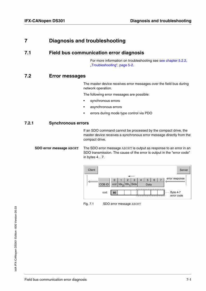
IFX-CANopen DS301 Diagnosis and troubleshootingIc
lA IF
X-C
AN
open
DS
301
Edi
tion
-000
Ver
sion
05.
03
7 Diagnosis and troubleshooting
7.1 Field bus communication error diagnosis
For more information on troubleshooting see see chapter 5.2.2, „Troubleshooting“, page 5-2.
7.2 Error messages
The master device receives error messages over the field bus during network operation.
The following error messages are possible:
• synchronous errors
• asynchronous errors
• errors during mode type control via PDO
7.2.1 Synchronous errors
If an SDO command cannot be processed by the compact drive, the master device receives a synchronous error message directly from the compact drive.
SDO error message ABORT The SDO error message ABORT is output as response to an error in an SDO transmission. The cause of the error is output in the "error code" in bytes 4…7.
Fig. 7.1 SDO error message ABORT
Client Server
1 2 3 4 5 6 70
COB ID ccd Idx2 Idx1 Sidx Data
error response
80ccd: Byte 4-7error code
Field bus communication error diagnosis 7-1

Diagnosis and troubleshooting IFX-CANopen DS301
IclA
IFX
-CA
Nop
en D
S30
1 E
ditio
n -0
00 V
ersi
on 0
5.03
Causes of a synchronous error Possible causes of a synchronous error are:
• error while executing an action or control command
• parameter value outside the permissible value range
• illegal action or control command during a running process
• access to an unknown object (index/subindex)
Table 7.1, page 7-2 shows all error messages that can occur during data exchange with the compact drive.
The byte sequence must be exchanged before evaluating according to the Intel format.
Example
Error code "0609 0011h" is sent as "11h 00h 09h 06h".
Error code Meaning
0504 0001h Command Code (ccd) not correct or unknown
0601 0002h No write access, because read object (ro)
0602 0000h Object not in object directory
0607 0010h Data type and parameter length do not match
0609 0011h Subindex not supported
0609 0030h Parameter value to large or too small (only relevant for write access)
0800 xxxxh Manufacturer-specific error "xxxx" corresponds to the error number of the compact drive. The error number can be found in the controller manual error number table
Table 7.1 Error codes
7-2 Error messages
IFX-CANopen DS301 Diagnosis and troubleshootingIc
lA IF
X-C
AN
open
DS
301
Edi
tion
-000
Ver
sion
05.
03
7.2.2 Asynchronous errors
If device errors occur, the compact drive monitoring devices report an asynchronous error.
For asynchronous errors that result in a movement interruption, the compact drive sends an EMCY message.
An asynchronous error is reported via various objects:
• In T_PDO4, driveStat and in the parameter Status.driveStat, 28:2 with the following bits:
– Bit 15, x_err
Error status during processing:evaluate cause via bits 5 and 6
– Bit 5
Error message of an internal monitoring signal (e.g. overtemperature)The error information is enter the Status.FltSig_SR, 28:18 parameter bit-coded.
– Bit 6
Error message of an external monitoring signal(e.g. movement interruption by limit switch)The exact cause is entered in the Status.Sign_SR, 28:15 parameter bit-coded.
– Bit 7 Controller warning message (e.g. warning of overtemperature)The error information is entered in the Status.WarnSig, 28:10 parameter bit-coded.
• The last error cause is also saved in the parameter Status.StopFault, 32:7 as error number. The list of error numbers and their meaning can be found in chapter 7, "Diagnosis and troubleshooting", of the controller manuals.
• As emergency message (EMCY) with the corresponding error number. The error number is identical to that in the parameter Status.StopFault, 32:7. For information on the EMCY object see Kapitel 4.4, "Emergency service", Seite 4-28.
Error messages 7-3
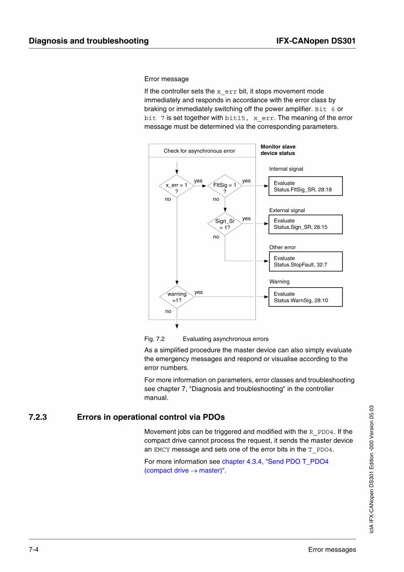
Diagnosis and troubleshooting IFX-CANopen DS301
IclA
IFX
-CA
Nop
en D
S30
1 E
ditio
n -0
00 V
ersi
on 0
5.03
Error message
If the controller sets the x_err bit, it stops movement mode immediately and responds in accordance with the error class by braking or immediately switching off the power amplifier. Bit 6 or bit 7 is set together with bit15, x_err. The meaning of the error message must be determined via the corresponding parameters.
Fig. 7.2 Evaluating asynchronous errors
As a simplified procedure the master device can also simply evaluate the emergency messages and respond or visualise according to the error numbers.
For more information on parameters, error classes and troubleshooting see chapter 7, "Diagnosis and troubleshooting" in the controller manual.
7.2.3 Errors in operational control via PDOs
Movement jobs can be triggered and modified with the R_PDO4. If the compact drive cannot process the request, it sends the master device an EMCY message and sets one of the error bits in the T_PDO4.
For more information see chapter 4.3.4, "Send PDO T_PDO4 (compact drive → master)".
EvaluateStatus.StopFault, 32:7
Check for asynchronous errorMonitor slavedevice status
x_err = 1?
yes
Warning
EvaluateStatus.FltSig_SR, 28:18
EvaluateStatus.WarnSig, 28:10
EvaluateStatus.Sign_SR, 28:15
warning=1?
yes
no
no
FltSig = 1?
yes
no
Sign_Sr= 1?
yes
no
Internal signal
External signal
Other error
7-4 Error messages

IFX-CANopen DS301 ServiceIc
lA IF
X-C
AN
open
DS
301
Edi
tion
-000
Ver
sion
05.
03
8 Service
8.1 Service address
Contact your local dealer with any questions or problems. Your dealer will be happy to give you the name of a customer service outlet in your area.
Service address 8-1

Service IFX-CANopen DS301
IclA
IFX
-CA
Nop
en D
S30
1 E
ditio
n -0
00 V
ersi
on 0
5.03
8-2 Service address

IFX-CANopen DS301 Object directoryIc
lA IF
X-C
AN
open
DS
301
Edi
tion
-000
Ver
sion
05.
03
9 Object directory
9.1 Overview
This object list describes the protocol for the compact drive in accordance with CANopen DS301 only. The objects for controlling the operating modes, operating functions and all parameters can be found in the compact drive manual.
9.1.1 Specifications for the objects
Index This index shows the position of the object in the object directory. The index value is shown in hexadecimal.
Object code The object code shows the data structure of the object.
Access ro: Read Only Value can only be read
rw: Read Write Value can be read and written
wo: Write Only Value can only be written
Object code Meaning Coding
VAR A single value, for example of the type Integer8, Unsigned32 or Visible String8.
7
ARR (ARRAY) A data field in which every entry is of the same data type.
8
REC (RECORD) A data field that contains entries that are a combination of single data types.
9
Data type Range of values Data length
Boolean 0 = false, 1 = true 1 byte
INT8 -128.. +127 1 byte
INT16 -32768.. +32767 2 bytes
INT32 -2147483648.. +2147483647 4 bytes
UINT8 0.. 255 1 byte
UINT16 0.. 65535 2 bytes
UINT32 0.. 4294967295 4 bytes
Visible String8 ASCII characters 8 bytes
Visible String16 ASCII characters 16 bytes
Overview 9-1

Object directory IFX-CANopen DS301
IclA
IFX
-CA
Nop
en D
S30
1 E
ditio
n -0
00 V
ersi
on 0
5.03
PDO R_PDO: Mapping for R_PDO possible
T_PDO: Mapping for T_PDO possible
No entry: PDP mapping not possible with the object
Range of values Show the permissible range in which the object value is defined and valid.
Default value The default values can be configured with the stored factory setting.
Can be saved Yes:values can be saved in the compact drive memory and are available again after switching on.
–: Values are lost when the compact drive is switched off.
9.1.2 Objects, overview
Index Subindex Designation Obj.code Data type Access
1000h device type VAR UINT32 ro
1001h error register VAR UINT8 ro
1008h manufacturer device name VAR String ro
100Ch guard time VAR UINT16 rw
100Dh life time factor VAR UINT8 rw
1015h inhibit time EMCY VAR UINT16 rw
1018h identity object RECORD Identity ro
1018h 0 number of elements VAR UINT8 ro
1018h 1 vendor id VAR UINT32 ro
1018h 2 product code VAR UINT8 ro
1403h receive PDO4 communication parameter RECORD PDO_Com ro
1403h 0 number of elements VAR UINT8 ro
1403h 1 COB-ID used by R_PDO4 VAR UINT32 ro
1403h 2 transmission type R_PDO4 VAR UINT8 rw
1403h 3 inhibit time R_PDO4 VAR UINT16 rw
1403h 4 compatibility entry R_PDO4 VAR UINT8 rw
1403h 5 event timer R_PDO4 VAR UINT16 rw
1603h receive PDO4 mapping RECORD PDO_Map ro
1603h 0 number of elements VAR UINT8 ro
1603h 1 1st mapped object R_PDO4 VAR UINT32 ro
1603h 2 2nd mapped object R_PDO4 VAR UINT32 ro
9-2 Overview

IFX-CANopen DS301 Object directoryIc
lA IF
X-C
AN
open
DS
301
Edi
tion
-000
Ver
sion
05.
03
1603h 3 3rd mapped object R_PDO4 VAR UINT32 ro
1603h 4 4th mapped object R_PDO4 VAR UINT32 ro
1803h transmit PDO4 communication parameter RECORD PDO_Com ro
1803h 0 number of elements VAR UINT8 ro
1803h 1 COB-ID used by T_PDO4 VAR UINT32 ro
1803h 2 transmission type T_PDO4 VAR UINT8 rw
1803h 3 inhibit time T_PDO4 VAR UINT16 rw
1803h 4 reserved T_PDO4 VAR UINT8 rw
1803h 5 event timer T_PDO4 VAR UINT16 rw
1A03h transmit PDO4 mapping RECORD PDO_Map ro
1A03h 0 number of elements VAR UINT8 ro
1A03h 1 1st mapped object T_PDO4 VAR UINT32 ro
1A03h 2 2nd mapped object T_PDO4 VAR UINT32 ro
1A03h 3 3rd mapped object T_PDO4 VAR UINT32 ro
1A03h 4 4th mapped object T_PDO4 VAR UINT32 ro
Index Subindex Designation Obj.code Data type Access
Overview 9-3

Object directory IFX-CANopen DS301
IclA
IFX
-CA
Nop
en D
S30
1 E
ditio
n -0
00 V
ersi
on 0
5.03
9.2 Objects of the compact drive
1000h Device type
The object shows the implemented device profile and the device type.
Object description
Values description
1001h Error register
The object shows the error status of the compact drive. The detailed error cause can be determined with the manufacturer-specific object Status.StopFault 32:7 .
Errors are signalled by an EMCY message as soon as they occur.
Object description
Values description
Index 1000h
Object name device typeObject code VARData type Unsigned32
Subindex 00h, device type
Meaning Device type and profileAccess read-onlyPDO mapping –Range of values –Default value 0Can be saved –
Index 1001hObject name error registerObject code VARData type Unsigned8
Subindex 00h, error register
Meaning error registerAccess read-onlyPDO mapping –Range of values –Default value –Can be saved –
9-4 Objects of the compact drive
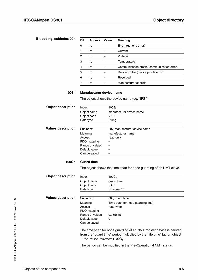
IFX-CANopen DS301 Object directoryIc
lA IF
X-C
AN
open
DS
301
Edi
tion
-000
Ver
sion
05.
03
Bit coding, subindex 00h
1008h Manufacturer device name
The object shows the device name (eg. "IFS ")
Object description
Values description
100Ch Guard time
The object shows the time span for node guarding of an NMT slave.
Object description
Values description
The time span for node guarding of an NMT master device is derived from the "guard time" period multiplied by the "life time" factor, object life time factor (100Dh).
The period can be modified in the Pre-Operational NMT status.
Bit Access Value Meaning
0 ro – Error! (generic error)
1 ro – Current
2 ro – Voltage
3 ro – Temperature
4 ro – Communication profile (communication error)
5 ro – Device profile (device profile error)
6 ro – Reserved
7 ro – Manufacturer specific
Index 1008h
Object name manufacturer device nameObject code VARData type String
Subindex 00h, manufacturer device name
Meaning manufacturer nameAccess read-onlyPDO mapping –Range of values –Default value –Can be saved –
Index 100Ch
Object name guard timeObject code VARData type Unsigned16
Subindex 00h, guard time
Meaning Time span for node guarding [ms]Access read-writePDO mapping –Range of values 0...65535Default value 0Can be saved –
Objects of the compact drive 9-5
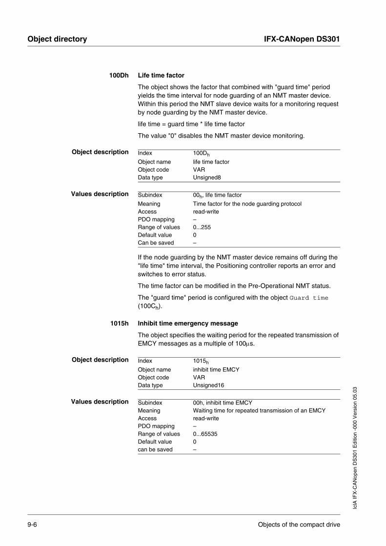
Object directory IFX-CANopen DS301
IclA
IFX
-CA
Nop
en D
S30
1 E
ditio
n -0
00 V
ersi
on 0
5.03
100Dh Life time factor
The object shows the factor that combined with "guard time" period yields the time interval for node guarding of an NMT master device. Within this period the NMT slave device waits for a monitoring request by node guarding by the NMT master device.
life time = guard time * life time factor
The value "0" disables the NMT master device monitoring.
Object description
Values description
If the node guarding by the NMT master device remains off during the "life time" time interval, the Positioning controller reports an error and switches to error status.
The time factor can be modified in the Pre-Operational NMT status.
The "guard time" period is configured with the object Guard time (100Ch).
1015h Inhibit time emergency message
The object specifies the waiting period for the repeated transmission of EMCY messages as a multiple of 100µs.
Object description
Values description
Index 100Dh
Object name life time factorObject code VARData type Unsigned8
Subindex 00h, life time factor
Meaning Time factor for the node guarding protocolAccess read-writePDO mapping –Range of values 0...255Default value 0Can be saved –
Index 1015h
Object name inhibit time EMCYObject code VARData type Unsigned16
Subindex 00h, inhibit time EMCYMeaning Waiting time for repeated transmission of an EMCYAccess read-writePDO mapping –Range of values 0...65535Default value 0can be saved –
9-6 Objects of the compact drive
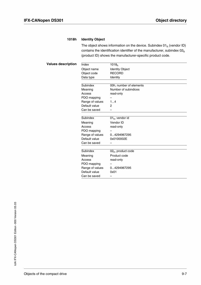
IFX-CANopen DS301 Object directoryIc
lA IF
X-C
AN
open
DS
301
Edi
tion
-000
Ver
sion
05.
03
1018h Identity Object
The object shows information on the device. Subindex 01h (vendor ID)
contains the identification identifier of the manufacturer, subindex 02h
(product ID) shows the manufacturer-specific product code.
Values description Index 1018h
Object name Identity ObjectObject code RECORDData type Identity
Subindex 00h, number of elementsMeaning Number of subindicesAccess read-onlyPDO mapping –Range of values 1...4Default value 2Can be saved –
Subindex 01h, vendor id
Meaning Vendor IDAccess read-onlyPDO mapping –Range of values 0...4294967295Default value 0x0100002ECan be saved –
Subindex 02h, product code
Meaning Product codeAccess read-onlyPDO mapping –Range of values 0...4294967295Default value 0x01Can be saved –
Objects of the compact drive 9-7
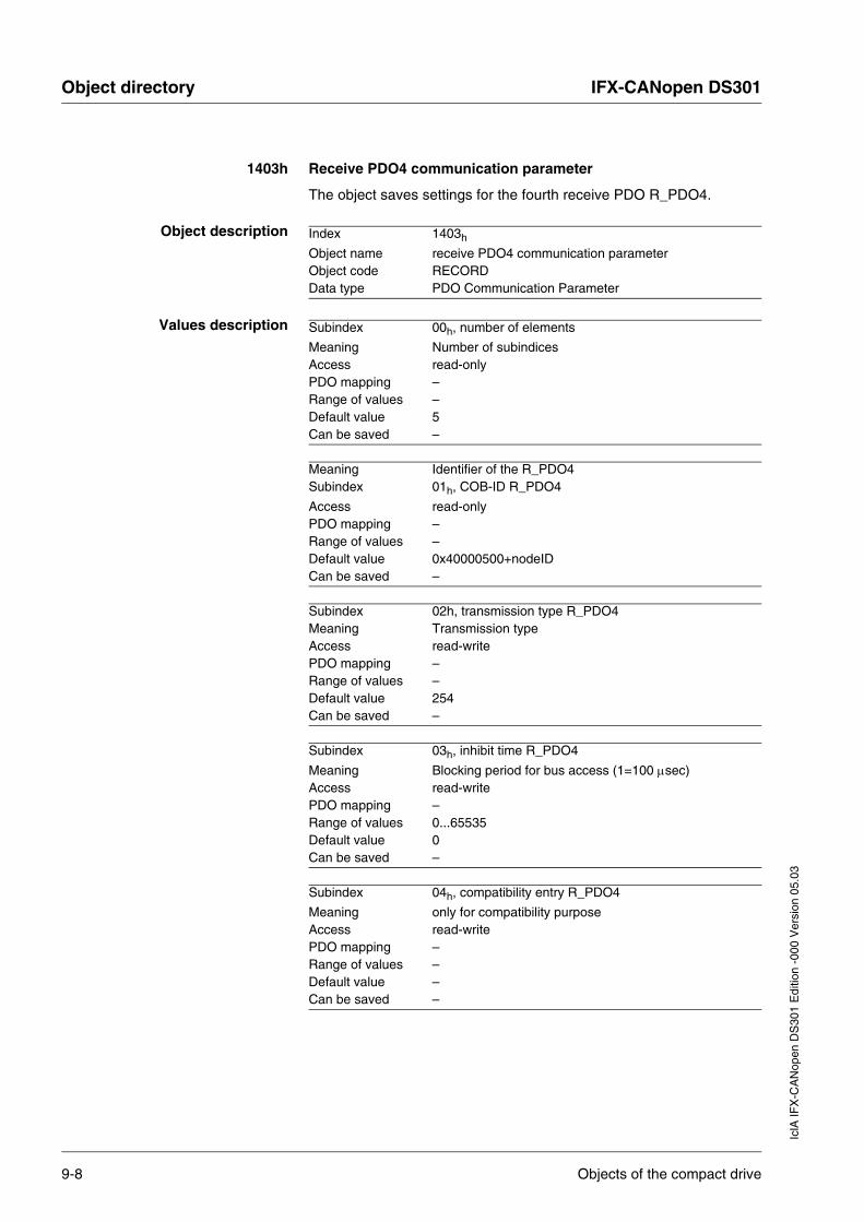
Object directory IFX-CANopen DS301
IclA
IFX
-CA
Nop
en D
S30
1 E
ditio
n -0
00 V
ersi
on 0
5.03
1403h Receive PDO4 communication parameter
The object saves settings for the fourth receive PDO R_PDO4.
Object description
Values description
Index 1403h
Object name receive PDO4 communication parameterObject code RECORDData type PDO Communication Parameter
Subindex 00h, number of elements
Meaning Number of subindicesAccess read-onlyPDO mapping –Range of values –Default value 5Can be saved –
Meaning Identifier of the R_PDO4Subindex 01h, COB-ID R_PDO4
Access read-onlyPDO mapping –Range of values –Default value 0x40000500+nodeIDCan be saved –
Subindex 02h, transmission type R_PDO4Meaning Transmission typeAccess read-writePDO mapping –Range of values –Default value 254Can be saved –
Subindex 03h, inhibit time R_PDO4
Meaning Blocking period for bus access (1=100 µsec)Access read-writePDO mapping –Range of values 0...65535Default value 0Can be saved –
Subindex 04h, compatibility entry R_PDO4
Meaning only for compatibility purposeAccess read-writePDO mapping –Range of values –Default value –Can be saved –
9-8 Objects of the compact drive
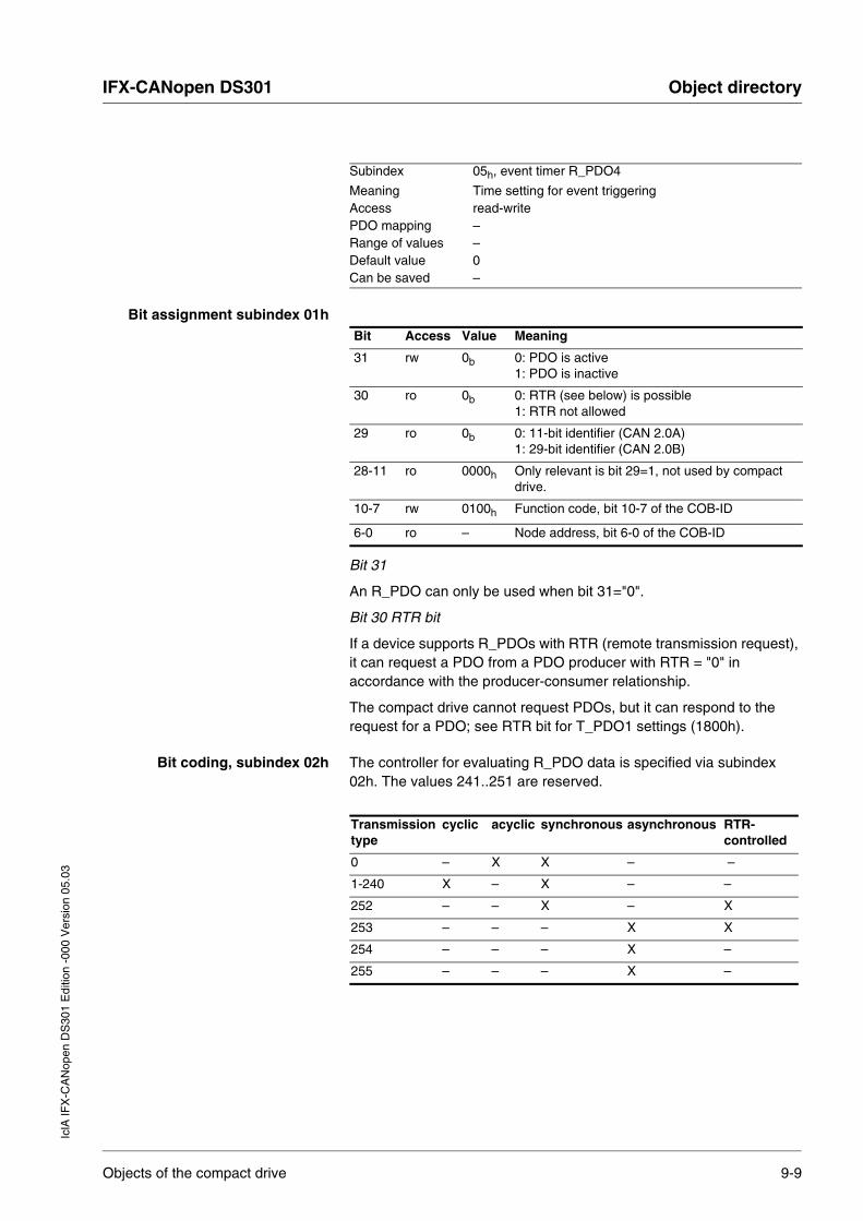
IFX-CANopen DS301 Object directoryIc
lA IF
X-C
AN
open
DS
301
Edi
tion
-000
Ver
sion
05.
03
Bit assignment subindex 01h
Bit 31
An R_PDO can only be used when bit 31="0".
Bit 30 RTR bit
If a device supports R_PDOs with RTR (remote transmission request), it can request a PDO from a PDO producer with RTR = "0" in accordance with the producer-consumer relationship.
The compact drive cannot request PDOs, but it can respond to the request for a PDO; see RTR bit for T_PDO1 settings (1800h).
Bit coding, subindex 02h The controller for evaluating R_PDO data is specified via subindex 02h. The values 241..251 are reserved.
Subindex 05h, event timer R_PDO4
Meaning Time setting for event triggeringAccess read-writePDO mapping –Range of values –Default value 0Can be saved –
Bit Access Value Meaning
31 rw 0b 0: PDO is active 1: PDO is inactive
30 ro 0b 0: RTR (see below) is possible 1: RTR not allowed
29 ro 0b 0: 11-bit identifier (CAN 2.0A) 1: 29-bit identifier (CAN 2.0B)
28-11 ro 0000h Only relevant is bit 29=1, not used by compact drive.
10-7 rw 0100h Function code, bit 10-7 of the COB-ID
6-0 ro – Node address, bit 6-0 of the COB-ID
Transmission type
cyclic acyclic synchronous asynchronous RTR-controlled
0 – X X – –
1-240 X – X – –
252 – – X – X
253 – – – X X
254 – – – X –
255 – – – X –
Objects of the compact drive 9-9
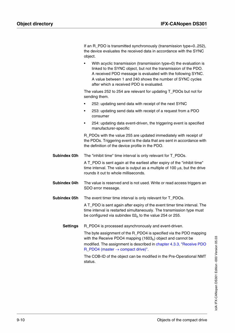
Object directory IFX-CANopen DS301
IclA
IFX
-CA
Nop
en D
S30
1 E
ditio
n -0
00 V
ersi
on 0
5.03
If an R_PDO is transmitted synchronously (transmission type=0..252), the device evaluates the received data in accordance with the SYNC object.
• With acyclic transmission (transmission type=0) the evaluation is linked to the SYNC object, but not the transmission of the PDO. A received PDO message is evaluated with the following SYNC.A value between 1 and 240 shows the number of SYNC cycles after which a received PDO is evaluated.
The values 252 to 254 are relevant for updating T_PDOs but not for sending them.
• 252: updating send data with receipt of the next SYNC
• 253: updating send data with receipt of a request from a PDO consumer
• 254: updating data event-driven, the triggering event is specified manufacturer-specific
R_PDOs with the value 255 are updated immediately with receipt of the PDOs. Triggering event is the data that are sent in accordance with the definition of the device profile in the PDO.
Subindex 03h The "inhibit time" time interval is only relevant for T_PDOs.
A T_PDO is sent again at the earliest after expiry of the "inhibit time" time interval. The value is output as a multiple of 100 µs, but the drive rounds it out to whole milliseconds.
Subindex 04h The value is reserved and is not used. Write or read access triggers an SDO error message.
Subindex 05h The event timer time interval is only relevant for T_PDOs.
A T_PDO is sent again after expiry of the event timer time interval. The time interval is restarted simultaneously. The transmission type must be configured via subindex 02h to the value 254 or 255.
Settings R_PDO4 is processed asynchronously and event-driven.
The byte assignment of the R_PDO4 is specified via the PDO mapping with the Receive PDO4 mapping (1603h) object and cannot be
modified. The assignment is described in chapter 4.3.3, "Receive PDO R_PDO4 (master → compact drive)".
The COB-ID of the object can be modified in the Pre-Operational NMT status.
9-10 Objects of the compact drive

IFX-CANopen DS301 Object directoryIc
lA IF
X-C
AN
open
DS
301
Edi
tion
-000
Ver
sion
05.
03
1603h Receive PDO4 mapping
The object shows which objects are mapped in R_PDO4 and transmitted with the PDO. When reading the object subindex 00h the number of mapped objects is given.
Object description
Values description
Index 1603hObject name receive PDO4 mappingObject code RECORDData type PDO mapping
Subindex 00h, number of elementsMeaning Number of subindicesAccess read-onlyPDO mapping –Range of values –Default value 4Can be saved –
Subindex 01h, 1st mapped object R_PDO4
Meaning First object for the mapping in R_PDO4Access read-onlyPDO mapping –Range of values –Default value 0x301E0108Can be saved –
Subindex 02h, 2nd mapped object R_PDO4
Meaning Second object for the mapping in R_PDO4Access read-onlyPDO mapping –Range of values –Default value 0x301E0208Can be saved –
Subindex 03h, 3rd mapped object R_PDO4
Meaning Third object for the mapping in R_PDO4Access read-onlyPDO mapping –Range of values –Default value 0x301E0510Can be saved –
Subindex 04h, 4th mapped object R_PDO4
Meaning Fourth object for the mapping in R_PDO4Access read-onlyPDO mapping –Range of values –Default value 0x301E0620Can be saved –
Objects of the compact drive 9-11
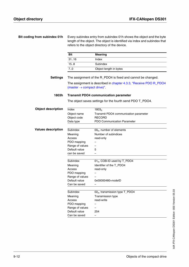
Object directory IFX-CANopen DS301
IclA
IFX
-CA
Nop
en D
S30
1 E
ditio
n -0
00 V
ersi
on 0
5.03
Bit coding from subindex 01h Every subindex entry from subindex 01h shows the object and the byte length of the object. The object is identified via index and subindex that refers to the object directory of the device.
Settings The assignment of the R_PDO4 is fixed and cannot be changed.
The assignment is described in chapter 4.3.3, "Receive PDO R_PDO4 (master → compact drive)".
1803h Transmit PDO4 communication parameter
The object saves settings for the fourth send PDO T_PDO4.
Object description
Values description
Bit Meaning
31..16 Index
15..8 Subindex
7..0 Object length in bytes
Index 1803h
Object name Transmit PDO4 communication parameterObject code RECORDData type PDO Communication Parameter
Subindex 00h, number of elements
Meaning Number of subindicesAccess read-onlyPDO mapping –Range of values –Default value 5can be saved –
Subindex 01h, COB-ID used by T_PDO4
Meaning Identifier of the T_PDO4Access read-onlyPDO mapping –Range of values –Default value 0x00000480+nodeIDCan be saved –
Subindex 02h, transmission type T_PDO4
Meaning Transmission typeAccess read-writePDO mapping –Range of values –Default value 254Can be saved –
9-12 Objects of the compact drive

IFX-CANopen DS301 Object directoryIc
lA IF
X-C
AN
open
DS
301
Edi
tion
-000
Ver
sion
05.
03
The meaning of the bit states and subindex values is described with the object receive PDO4 communication parameters (1403h).
Settings R_PDO4 is sent asynchronously and event-driven.
The byte assignment of the T_PDO4 is specified via the PDO mapping with the Transmit PDO4 mapping (1A03h) object and cannot be
modified. The assignment is described in chapter 4.3.4, "Send PDO T_PDO4 (compact drive → master)".
The COB-ID of the object can be modified in the Pre-Operational NMT status.
Subindex 03h, inhibit time T_PDO4
Meaning Blocking period for bus access (in [100 µsec]). The value is round off to whole milliseconds by the drive.
Access read-writePDO mapping –Range of values 0...65535Default value 0Can be saved –
Subindex 04h, reserved T_PDO4
Meaning reserved (only for compatibility purpose)Access read-writePDO mapping –Range of values –Default value –Can be saved –
Subindex 05h, event timer T_PDO4Meaning Time setting for event triggeringAccess read-writePDO mapping –Range of values –Default value 0Can be saved –
Objects of the compact drive 9-13

Object directory IFX-CANopen DS301
IclA
IFX
-CA
Nop
en D
S30
1 E
ditio
n -0
00 V
ersi
on 0
5.03
1A03h Transmit PDO4 mapping
The object shows which objects are mapped in T_PDO4 and transmitted with the PDO. When reading the object subindex 00h the number of mapped objects is given.
Object description
Values description
The meaning of the bit states is described with the object receive PDO4 mapping (1603h).
Index 1A03h
Object name transmit PDO4 mappingObject code RECORDData type PDO mapping
Subindex 00h, number of elements
Meaning Number of subindicesAccess read-onlyPDO mapping –Range of values –Default value 4Can be saved –
Subindex 01h, 1st mapped object T_PDO4
Meaning First object for the mapping in T_PDO4Access read-onlyPDO mapping –Range of values –Default value 0x301E0410Can be saved –
Subindex 02h, 2nd mapped object T_PDO4
Meaning Second object for the mapping in T_PDO4Access read-onlyPDO mapping –Range of values –Default value 0x301E0308Can be saved –
Subindex 03h, 3rd mapped object T_PDO4
Meaning Third object for the mapping in T_PDO4Access read-onlyPDO mapping –Range of values –Default value 0x301E0708Can be saved –
Subindex 04h, 4th mapped object T_PDO4
Meaning Fourth object for the mapping in T_PDO4Access read-onlyPDO mapping –Range of values –Default value 0x301E0820Can be saved –
9-14 Objects of the compact drive

IFX-CANopen DS301 Object directoryIc
lA IF
X-C
AN
open
DS
301
Edi
tion
-000
Ver
sion
05.
03
Settings The PDO assignment for T_PDO4 cannot be modified. The assignment is described in chapter 4.3.4, "Send PDO T_PDO4 (compact drive → master)".
Objects of the compact drive 9-15

Object directory IFX-CANopen DS301
IclA
IFX
-CA
Nop
en D
S30
1 E
ditio
n -0
00 V
ersi
on 0
5.03
9-16 Objects of the compact drive

IFX-CANopen DS301 GlossariesIc
lA IF
X-C
AN
open
DS
301
Edi
tion
-000
Ver
sion
05.
03
10 Glossaries
10.1 Abbreviations
Abbreviation Meaning
CAN Controller Area Network, standardized bus system
CDD Command Code, a component of an SDO message
COB Communication Object, basic object for transport of data in a CAN network. 2048 COBs are permissible in a CAN network and can be identified by a unique COB-ID.
COB-ID Communication object identifier, component of the CANopen message for identification of objects and specification of bus access priorities
DS Draft standard draft standard
DSP Draft standard proposal, proposed standard draft
PDO Process Data Object, object for fast transport of data in the CAN network. They are classified into T_PDO (Transmit PDO) for sending data and R_PDO (Receive PDO) for receiving data
R_PDO Receive Process Data Object, process data from the master device to the drive
R_SDO Receive Service Data Object, configuration data from the master device to the drive
RTR Remote Transmission Request
SDO Service Data Object, object for transport of system data, including distributed over multiple SDO messages
SYNC Synchronisation object, object for synchronising devices on the network node-ID node address
T_PDO Transmit Process Data Object, process data from the drive to the master device
T_SDO Transmit Service Data Object, configuration data from the drive to the master device
Abbreviations 10-1

Glossaries IFX-CANopen DS301
IclA
IFX
-CA
Nop
en D
S30
1 E
ditio
n -0
00 V
ersi
on 0
5.03
10.2 Glossary
Broadcast Type of data transmission in the network; a device sends a message to all devices on the network
Bus arbitration Device on the field bus for prevention of data collisions when multiple bus devices transmit simultaneously. The station that is ready to transmit and has the higher priority receives the authority. The priority is specified by the COB-ID.
CAN connection Communications interface of the positioning drive for connection to the CAN bus
Client First the sender, then the receiver of CAN messages in the client-server relationship starts the transmission with a transmission to the server; the reference point is the server object directory.
Consumer Receiver of CAN messages in the producer-consumer relationship of network devices (consumer).
Default values Factory setting, values preset on delivery from the factory
Error class Classification of operational faults into groups corresponding to the error responses
Event timer The sequence of an event-driven time interval triggers transmission of a PDO message Event-driven time intervals can be set in parallel to other event-driven functions such as to change the signal of a monitored device input (event timer)
Heartbeat Heartbeat is a monitoring function with which a network device can check whether another network device is ready to send and receive (heartbeat)
Index The index is 16-bit long value with which every object in the object directory of a device can be uniquely addressed.
Inhibit time A minimum waiting time for repeated transmission can be set for a PDO to reduce the data transfer load on the field bus. After the first transmission the PDO is sent again only after expiry of the waiting time (inhibit time)
Master First the sender, then the receiver of CAN messages in a master-slave relationship of network devices; the master device control the communications of the slaves (master)
Node address Address of a device in the network; every device in the network has a unique node address
Node guarding Node guarding is a monitoring function with which one or more network devices is regularly checked for readiness to send and receive (node guarding)
Parameter Device data and values that can be set by the user.
Producer Creator of CAN messages in the producer-consumer relationship of network devices (producer)
Server First the sender, then the receiver of CAN messages in the client-server relationship responds to the request of a clients; the reference point is the server object directory (server)
10-2 Glossary
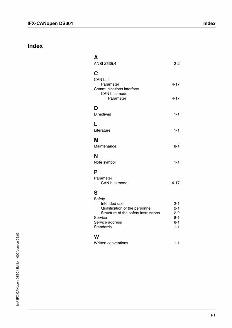
IFX-CANopen DS301 IndexIc
lA IF
X-C
AN
open
DS
301
Edi
tion
-000
Ver
sion
05.
03
Index
AANSI Z535.4 2-2
CCAN bus
Parameter 4-17Communications interface
CAN bus modeParameter 4-17
DDirectives 1-1
LLiterature 1-1
MMaintenance 8-1
NNote symbol 1-1
PParameter
CAN bus mode 4-17
SSafety
Intended use 2-1Qualification of the personnel 2-1Structure of the safety instructions 2-2
Service 8-1Service address 8-1Standards 1-1
WWritten conventions 1-1
I-1

Index IFX-CANopen DS301
IclA
IFX
-CA
Nop
en D
S30
1 E
ditio
n -0
00 V
ersi
on 0
5.03
I-2

IclA
IFX
-CA
Nop
en D
S30
1 E
ditio
n -0
00 V
ersi
on 0
5.03
IFX-CANopen DS301 Supplement
Supplement

IclA
IFX
-CA
Nop
en D
S30
1 E
ditio
n -0
00 V
ersi
on 0
5.03
Supplement IFX-CANopen DS301