ieee transactions on terahertz science and...
TRANSCRIPT

IEEE TRANSACTIONS ON TERAHERTZ SCIENCE AND TECHNOLOGY, VOL. 2, NO. 2, MARCH 2012 177
Design and Characterization of a Room TemperatureAll-Solid-State Electronic Source Tunable
From 2.48 to 2.75 THzAlain Maestrini, Member, IEEE, Imran Mehdi, Fellow, IEEE, José V. Siles, Member, IEEE,
John S. Ward, Member, IEEE, Robert Lin, Bertrand Thomas, Choonsup Lee, John Gill,Goutam Chattopadhyay, Fellow, IEEE, Erich Schlecht, John Pearson, and Peter Siegel, Fellow, IEEE
Abstract—We report on the design, fabrication and test ofan all-solid-state, frequency agile source that produces over1 W � 30 dBm� across the 2.48–2.75 THz band at room temper-ature. This frequency-multiplied source is driven by a -bandsynthesizer followed by a power amplifier that delivers 350–450mW (25.5–26.5 dBm) and a cascade of three balanced frequencytriplers. The first stage tripler is based on four power-combinedsix-anode GaAs Schottky diode devices, and the second stagetripler is based on two four-anode GaAs devices. The outputtripler uses a single unbiased device featuring two anodes mono-lithically integrated onto a thin GaAs membrane. The sourcedelivers a record 18 W � 17.5 dBm� at 2.58 THz at roomtemperature. This frequency multiplied source is analyzed witha Fourier transform spectrometer (FTS) and the unwanted har-monics are found to be at least 29 dB below the desired signal.This source, when used as the local oscillator for a hot-electronbolometer mixer, will enable heterodyne instruments for futurespace missions to map the cosmologically-important 2.675 THzHD molecular line.
Index Terms—Broadband terahertz (THz) source, frequencymultiplier, frequency tripler, local oscillator, planar diode,power-combining, Schottky diode, THz, varactor.
I. INTRODUCTION
T HE 2–3 THz frequency range lies in the “terahertz gap,”namely, a frequency range that has been historically too
high for electronic devices and too low for photonic devices.A major reason for the lack of instrumentation in this regimeis the dearth of terahertz sources. Electronic sources for the
Manuscript received September 07, 2011; accepted December 09, 2011. Dateof publication February 20, 2012; date of current version March 02, 2012. Thiswork was supported by National Aeronautics and Space Administration under acontract, at the Université Pierre et Marie Curie-Paris 6, and at the Observatoirede Paris, France. Funding from NASA Astrophysics Research and Analysis Pro-gram (APRA), Université Pierre et Marie Curie and Centre National d’EtudesSpatiales.
A. Maestrini is with the Université Pierre et Marie Curie-Paris6, Paris,France and with the Observatoire de Paris, LERMA, France (e-mail:[email protected]).
I. Mehdi, J. V. Siles, J. Gill, C. Lee, R. Lin, G. Chattopadhyay, E. Schlecht, J.Pearson, and P. Siegel are with the Jet Propulsion Laboratory, California Insti-tute of Technology, Pasadena, CA 91125 USA (e-mail: [email protected]; [email protected]).
J. S. Ward was with the Jet Propulsion Laboratory, Pasadena, CA 91109 USA.He is now with Raytheon Company, Fort Wayne, IN USA.
B. Thomas was with the Jet Propulsion Laboratory, Pasadena, CA 91109USA. He is now with Radiometer Physics GmbH, Meckenheim, Germany.
Color versions of one or more of the figures in this paper are available onlineat http://ieeexplore.ieee.org.
Digital Object Identifier 10.1109/TTHZ.2012.2183740
Heterodyne Instrument for the Far Infrared (HIFI) onboard theHerschel Space Observatory (launched in 2009) [1], [2], workup to 1.9 THz using -band power amplifiers driving planarSchottky diode frequency multipliers. Herschel, now stationed1.5 million kilometers from Earth, provides valuable high-reso-lution spectroscopic observations of the cold Universe [3], [4].Herschel provided a strong impetus towards the developmentof broadband terahertz sources. However, due to the immatu-rity of local oscillator (LO) technology, it does not include a2.5–2.7 THz channel in its suite of receivers, which was highlydesired to observe the rotational spectral line of HDat 2.675 THz [5].
Electronic sources based on microwave oscillators followedby a combination of frequency multipliers and amplifiers areinherently phase-lockable and frequency agile, are robust, workboth at room temperature and cryogenic temperatures and aresufficiently efficient to be the technology of choice for local os-cillators of heterodyne instruments [6]. However, limitations in-cluding low output power and (until now) low technology readi-ness level have led to the development of a variety of alternateterahertz source technologies.
Introduced in 2002, terahertz quantum cascaded lasers(QCLs) are solid-state sources able to deliver several milli-watts of continuous wave (CW) power [7]. Though terahertzQCLs have already been employed in laboratories for pumpinglow-noise heterodyne receivers at a fixed frequency of 2.8 THz[8], QCLs only operate at cryogenic temperatures, frequencytuning is severely limited, and consequently, a QCL-basedLO suitable for an airborne, balloon-borne or space-borneobservatory has not been demonstrated. Photo-mixers havealso been developed for the purpose of building an LO in thisfrequency range. They have the advantage of being tunableover a large bandwidth, but are still limited to sub-microwattlevels at 2.5 THz and require cryogenic cooling [9]. A novelfrequency-tunable photonic source, based on shining two lasersonto a non-linear crystal, was able to produce 2 mW at 1.9THz at room temperature [10]. However, this source requireshundreds of watts of optical power, which makes it useful onlyfor some ground-based applications.
We describe herein the first demonstration of a 2.48–2.75THz solid-state source that produces power levels of several mi-crowatts at room temperature. This source has already been ex-tensively used in the laboratory for high resolution spectroscopyof molecular gases like CH OH, H O and HD at ultra-high res-olution and frequency accuracy [11]. It enabled measurements
2156-342X/$31.00 © 2012 IEEE

178 IEEE TRANSACTIONS ON TERAHERTZ SCIENCE AND TECHNOLOGY, VOL. 2, NO. 2, MARCH 2012
with an unprecedented signal to noise ratio and was notable forits ease of use. This paper presents the design of this frequencymultiplied source with an emphasis on the last stage frequencymultiplier at 2.7 THz. Various test setups that were utilized tocharacterize the source power versus frequency and its spectralpurity will also be discussed.
It is noteworthy that other teams are also developing terahertzfrequency-multiplied sources. Of particular interest is a recentresult reported shortly after [11] was published of a source usedas a local oscillator in a terahertz heterodyne receiver devel-oped for radio astronomy. This source produced a peak powerof W at 2.56 THz and has been successfully flown onboardSOFIA [12].
II. DESIGN AND FABRICATION
This section will discuss in detail the key new element of the2.7 THz source: the last stage frequency tripler.
A. Balanced Design, Conversion Efficiency and SpectralPurity
The last stage frequency multiplier relies on the topology thathas been successfully demonstrated up to 1.9 THz onboard theHerschel Space Observatory. The circuit is balanced, with twoSchottky diodes in series at dc (see Fig. 1) that form a virtualloop to trap the second harmonic of the input signal and maxi-mize the transfer of energy to the third harmonic, i.e., the outputsignal. This topology offers the advantage of a very small phaseshift between the two anodes and the possibility to tune thematching at the second harmonic by adjusting the length of thebeam-leads that ground the diodes and by adjusting the crosssection of the channel where the chip is mounted. An E-planeprobe located in the input waveguide couples the input signal toa suspended microstrip line. This line is connected to a one-celllow-pass filter to prevent the third harmonic from leaking intothe input waveguide. The third harmonic produced by the diodesis coupled to the output waveguide by a second E-plane probe. Inorder to balance the circuit, the dimensions of both the channeland the circuit are chosen to cut off the TE-mode at the secondharmonic. A detailed description of this type of tripler has beenpresented previously [13]–[15]. The dimensions of the outputwaveguide are chosen to cut off any signal below 2 THz, whichensures that the third harmonic of the input signal emitted in the2.48–2.75 THz band is not contaminated by any signal at thefundamental or second harmonic. Note that in practice, due toan imperfect balance, some parasitic power at the second har-monic might propagate outside the diode loop toward the cir-cuit inside the channel in a quasi-TEM mode, like the third har-monic of the input signal. Though imperfect, the balanced ge-ometry of the circuit ensures that power at the even harmonics ofthe input are efficiently suppressed, leaving the fifth harmonicas the dominant unwanted harmonic at the output. Fortunately,given the high order of multiplication and the high frequency,very little power is expected to be produced by the diodes at thefifth harmonic.
B. Device and Circuit Models
The design of Schottky diode based frequency multipliersbeyond 2 THz becomes very challenging due to the size ofthe chip and the waveguide dimensions required for the proper
Fig. 1. Schematic of the 2.7 THz final stage balanced tripler. Assuming a per-fect balance between the diodes, the electric fields and the current lines are repre-sented for the fundamental frequency � (thick plain lines), the frequency �� �
(dashed lines) and the output frequency � � � (light plain lines.) The inputsignal at � and the output signal at �� � propagate on a quasi-TEM mode.
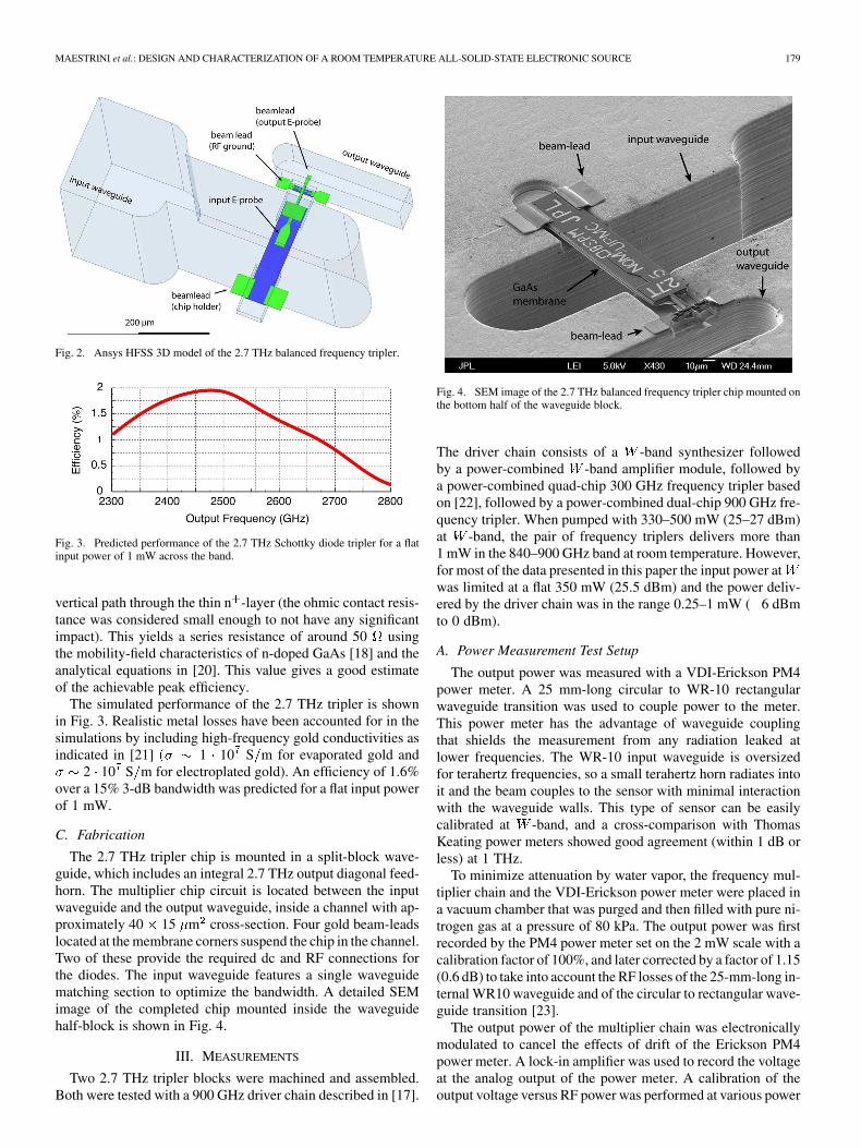
impedance matching of the multiplier circuit. In addition, lim-ited available input power necessitates precise modeling of boththe Schottky diode and the matching circuit in order to drive thediodes into their nonlinear regimes [16]. Based on results ob-tained from the 900 GHz driver stage [17], the design of the2.7 THz tripler was optimized for about 1 mW of input power.The general design method presented in [13] and [17] was ap-plied. It is iterative and consists in decomposing the multiplierstructure in several blocks that are analyzed separately withAnsys High Frequency Structure Simulator (HFSS)1. The S-pa-rameters corresponding to the different blocks are included ina custom non-linear circuit model implemented in Agilent Ad-vanced Design System (ADS)2. The harmonic balance simulatorof ADS is then used to predict the performance of the frequencymultiplier in terms of input matching, conversion efficiency, andoutput power. Fig. 2 shows the complete HFSS 3D model of the2.7 THz frequency tripler.
The 2.7 THz frequency tripler features two Schottkyplanar varactor diodes with nominal anode area of around0.15 m deposited on an epilayer of GaAs doped enoughtypically 2 10 cm to mitigate the effect of carrier
velocity saturation at high frequencies. The epilayer lies ontop of a mesa of heavily doped GaAs
1 10 cm . The nonlinear response of the diodes issimulated using the standard model available in ADS adjustedfor the junction capacitance, with other parameters estimatedusing the classic equations found in [18]. In addition, to accountfor fringe effects in the junction capacitance, a correction factorwas included in the model [19]. An approximate value for theseries resistance is calculated assuming that the epilayer of thediodes is fully depleted at the optimum operating conditionand that the actual path of the current flow is equivalent to a
1HFSS, Ansys Inc., Pittsburg, PA.2ADS, Agilent Technologies, Palo Alto, CA.
MAESTRINI et al.: DESIGN AND CHARACTERIZATION OF A ROOM TEMPERATURE ALL-SOLID-STATE ELECTRONIC SOURCE 179
Fig. 2. Ansys HFSS 3D model of the 2.7 THz balanced frequency tripler.
Fig. 3. Predicted performance of the 2.7 THz Schottky diode tripler for a flatinput power of 1 mW across the band.
vertical path through the thin n -layer (the ohmic contact resis-tance was considered small enough to not have any significantimpact). This yields a series resistance of around 50 usingthe mobility-field characteristics of n-doped GaAs [18] and theanalytical equations in [20]. This value gives a good estimateof the achievable peak efficiency.
The simulated performance of the 2.7 THz tripler is shownin Fig. 3. Realistic metal losses have been accounted for in thesimulations by including high-frequency gold conductivities asindicated in [21] 1 10 S m for evaporated gold and
2 10 S m for electroplated gold). An efficiency of 1.6%over a 15% 3-dB bandwidth was predicted for a flat input powerof 1 mW.
C. Fabrication
The 2.7 THz tripler chip is mounted in a split-block wave-guide, which includes an integral 2.7 THz output diagonal feed-horn. The multiplier chip circuit is located between the inputwaveguide and the output waveguide, inside a channel with ap-proximately 40 15 m cross-section. Four gold beam-leadslocated at the membrane corners suspend the chip in the channel.Two of these provide the required dc and RF connections forthe diodes. The input waveguide features a single waveguidematching section to optimize the bandwidth. A detailed SEMimage of the completed chip mounted inside the waveguidehalf-block is shown in Fig. 4.
III. MEASUREMENTS
Two 2.7 THz tripler blocks were machined and assembled.Both were tested with a 900 GHz driver chain described in [17].
Fig. 4. SEM image of the 2.7 THz balanced frequency tripler chip mounted onthe bottom half of the waveguide block.
The driver chain consists of a -band synthesizer followedby a power-combined -band amplifier module, followed bya power-combined quad-chip 300 GHz frequency tripler basedon [22], followed by a power-combined dual-chip 900 GHz fre-quency tripler. When pumped with 330–500 mW (25–27 dBm)at -band, the pair of frequency triplers delivers more than1 mW in the 840–900 GHz band at room temperature. However,for most of the data presented in this paper the input power atwas limited at a flat 350 mW (25.5 dBm) and the power deliv-ered by the driver chain was in the range 0.25–1 mW ( 6 dBmto 0 dBm).
A. Power Measurement Test Setup
The output power was measured with a VDI-Erickson PM4power meter. A 25 mm-long circular to WR-10 rectangularwaveguide transition was used to couple power to the meter.This power meter has the advantage of waveguide couplingthat shields the measurement from any radiation leaked atlower frequencies. The WR-10 input waveguide is oversizedfor terahertz frequencies, so a small terahertz horn radiates intoit and the beam couples to the sensor with minimal interactionwith the waveguide walls. This type of sensor can be easilycalibrated at -band, and a cross-comparison with ThomasKeating power meters showed good agreement (within 1 dB orless) at 1 THz.
To minimize attenuation by water vapor, the frequency mul-tiplier chain and the VDI-Erickson power meter were placed ina vacuum chamber that was purged and then filled with pure ni-trogen gas at a pressure of 80 kPa. The output power was firstrecorded by the PM4 power meter set on the 2 mW scale with acalibration factor of 100%, and later corrected by a factor of 1.15(0.6 dB) to take into account the RF losses of the 25-mm-long in-ternal WR10 waveguide and of the circular to rectangular wave-guide transition [23].
The output power of the multiplier chain was electronicallymodulated to cancel the effects of drift of the Erickson PM4power meter. A lock-in amplifier was used to record the voltageat the analog output of the power meter. A calibration of theoutput voltage versus RF power was performed at various power

180 IEEE TRANSACTIONS ON TERAHERTZ SCIENCE AND TECHNOLOGY, VOL. 2, NO. 2, MARCH 2012
Fig. 5. Output power versus frequency at room temperature of JPL 2.7 THzsource SN4 in a pure nitrogen atmosphere (top thick curve with square markers),and in a laboratory atmosphere (bottom dashed curve with cross markers).
levels in the range 5–200 W ( 23 dBm to 7 dBm) using areference source at -band and a precision attenuator. The cal-ibration consisted in comparing the reading of the PM4 meterwith no modulation to the output voltage of the lock-in ampli-fier when the modulation to the RF signal was applied. The lin-earity of the measurement system was checked down to powerlevels as low as 100 nW 40 dBm by attenuating the -bandsource. Integration times of several minutes were necessary torecord such low power levels.
The ratio between the detected RF power and output voltageof the lock-in amplifier does not depend on the RF frequency, itdepends only on the time constant of the detector/power meter,modulation frequency, and settings on the lock-in amplifier it-self. This method was double-checked at 2.7 THz when powerlevels exceeding 5 W 23 dBm were directly recorded onthe PM4 power-meter with no modulation applied.
B. Frequency Sweep
Two different frequency multiplier chains were tested acrossthe 2.48–2.75 THz band. The bias voltage applied to the300 GHz stage was fixed at 12 V in all the measurementspresented in this paper, and the voltage applied to the 900 GHzstage was set at 2 V for frequencies above 2.54 THz andoptimized in the 1 V to 0.2 V range for frequencies in the2.48–2.54 THz band. The input power at -band was held con-stant at 350 mW (25.5 dBm) for frequencies above 2.53 THzand rolled off below 2.53 THz to 155 mW at 2.48 THz. Thefrequency was set on an Agilent E8257D synthesizer connectedto an Agilent 83558A -band source module (a sextupler).The total frequency multiplication factor was 162.
For both chains, two sets of power measurements wererecorded, one in a pure nitrogen atmosphere and one in an at-mosphere including water vapor. This way, the H O absorptionlines at 2.5319 THz and at 2.6404 THz provide independentconfirmation of the output frequency. Figs. 5 and 6 show thatboth chains achieved unprecedented output power levels andbandwidth for an electronic source working in this frequencyrange at room temperature. Both chains delivered powers inexcess of 1 W 30 dBm across the full band.
The multiplier chain identified as SN4 (Fig. 5) deliv-ered a peak of 8 W dBm at 2.59 THz and de-
Fig. 6. Output power versus frequency at room temperature of JPL 2.7 THzsource SN6 in a pure nitrogen atmosphere (top thick curve with square markers),and in a nitrogen atmosphere with a slight amount of water vapor (bottom dashedcurve with cross markers).
livered W 24 dBm or more in the 2.49-2.69 THzband. The source labeled SN6 (Fig. 6) delivered a peak of14 W 18.5 dBm at 2.58 THz and 4 W dBm ormore in the 2.49–2.67 THz band. It can be seen that power inthis frequency range should be measured in a dry atmosphereor in vacuum, as strong absorptions were observed for a pathof only about 5 cm in air.
C. Power Sweep
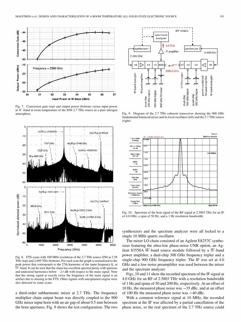
The input power at -band of the source SN6 wasswept from 110–450 mW (20.5–26.5 dBm) at the fixedfrequency of 2.58 THz (see Fig. 7). A record output power of18 W 17.5 dBm was measured. From Fig. 7 it can be seenthat the maximum conversion efficiency of this chain peaksat 4 10 44 dB for 350–400 mW (25.5–26 dBm) ofinput power. The saturation of the conversion gain is due tothe saturation of the two first stages of the chain, especially thefirst stage. In particular, the conversion gain of the first tripler(to 300 GHz) is expected to be maximized around 110 mW(20.5 dBm) of input power based on the data presented in [21].From 110 to 350 mW (20.5–5 dBm) of input power at -band,the decrease of the conversion gain of the first stage multiplieris compensated by an increase of the conversion gain of thesubsequent stages.
D. Wide-Band FTS Scans
The spectral purity of the 2.7 THz source SN6 was mea-sured from about 10 GHz to 6 THz using a Fourier transformspectrometer with 100 MHz resolution. Scans at different fre-quencies across the band at room temperature have been per-formed. Fig. 8 shows the measured response at two frequen-cies of interest, i.e., at 2.580 THz (with peak output power) andnear the astrophysically-significant HD line at 2.675 THz. Themultiplied source spectral purity is remarkably good with allhigh frequency spurious signals and undesired harmonics below
29 dB with respect to the main signal.
E. Spectral Analysis Near Carrier Frequency
The spectrum of the output signal was analyzed with anAnritsu MS2724B spectrum analyzer and an external bias-able900 GHz Schottky fundamental balanced mixer [24] used as
MAESTRINI et al.: DESIGN AND CHARACTERIZATION OF A ROOM TEMPERATURE ALL-SOLID-STATE ELECTRONIC SOURCE 181
Fig. 7. Conversion gain (top) and output power (bottom) versus input powerat� -band at room temperature of the SN6 2.7 THz source in a pure nitrogenatmosphere.
Fig. 8. FTS scans with 100 MHz resolution of the 2.7 THz source SN6 at 2.58THz (top) and 2.695 THz (bottom). For each scan the graph is normalized to thepeak power that corresponds to the 27th harmonic of the input frequency � at� -band. It can be seen that the chain has excellent spectral purity with spuriousand undesired harmonics below ��� dB with respect to the main signal. Notethat the strong signal at exactly twice the frequency of the main signal is anartifact due to aliasing in the FTS. Other signals with unexplained origins werealso detected in some scans.
a third-order subharmonic mixer at 2.7 THz. The frequencymultiplier chain output beam was directly coupled to the 900GHz mixer input horn with an air gap of about 0.5 mm betweenthe horn apertures. Fig. 9 shows the test configuration. The two
Fig. 9. Diagram of the 2.7 THz coherent transceiver showing the 900 GHzfundamental balanced mixer and its local oscillator (left) and the 2.7 THz source(right).
Fig. 10. Spectrum of the beat signal of the RF signal at 2.5803 THz for an IFof 4.0 GHz, a span of 50 Hz, and a 1 Hz resolution bandwidth.
synthesizers and the spectrum analyzer were all locked to asingle 10 MHz quartz oscillator.
The mixer LO chain consisted of an Agilent E8257C synthe-sizer featuring the ultra-low phase-noise UNR option, an Ag-ilent 83558A -band source module followed by a -bandpower amplifier, a dual-chip 300 GHz frequency tripler and asingle-chip 900 GHz frequency tripler. The IF was set at 4.0GHz and a low-noise preamplifier was used between the mixerand the spectrum analyzer.
Figs. 10 and 11 show the recorded spectrum of the IF signal at4.0 GHz for an RF of 2.5803 THz with a resolution bandwidthof 1 Hz and spans of 50 and 200 Hz, respectively. At an offset of10 Hz, the measured phase noise was 35 dBc, and at an offsetof 100 Hz the measured phase noise was 40 dBc.
With a common reference signal at 10 MHz, the recordedspectrum at the IF was affected by a partial cancellation of thephase noise, so the real spectrum of the 2.7 THz source could

182 IEEE TRANSACTIONS ON TERAHERTZ SCIENCE AND TECHNOLOGY, VOL. 2, NO. 2, MARCH 2012
Fig. 11. Spectrum of the beat signal of the RF signal at 2.5803 THz for an IFof 4.0 GHz, a span of 200 Hz, and a 1 Hz resolution bandwidth. The spectrumshows a modulation at 60 Hz.
not be directly derived from this experiment. However, the doc-umentation for the better of the two synthesizers specifies phasenoise of 70 dBc at 10 Hz from the carrier and at100 Hz for an output signal at 10 GHz [25]. Given a multipli-cation factor of 270 between 10 GHz and 2.7 THz, these valuesare expected to be degraded by 48 dB to become 22 dBc at10 Hz from the carrier and 39 dBc at 100 Hz from the car-rier. In other words, according to our measurements, the multi-plier chain does not introduce more phase noise in the 1–100 Hzband than the natural degradation of , where isthe order of multiplication. At 10 Hz we actually measured lessnoise due to the correlation between the two LO sources. Thisis an indication that when using an ultra-low noise commercialsynthesizer, the line at 2.7 THz should not collapse and shouldstay coherent [26]. We note spurious signals at 60 Hz offsets at
12 dBc. Although no detailed investigations were carried outto determine their exact origin, they are likely to be from powerline pick up.
IV. COMPARISON OF SIMULATIONS AND MEASUREMENTS
The predicted performance shown in Fig. 3 assumed a con-stant input power of 1 mW to the last stage tripler across theband. However, the actual power provided to this tripler is be-tween 0.2–0.95 mW in the 815–915 GHz band (see Fig. 12, topgraph). This leads to a decrease in the efficiency and bandwidthcompared to the predicted performance since the multiplier isunder-pumped. Fig. 12 shows a comparison between the mea-surement of the JPL 2.7 THz source SN6 (black dots) and sim-ulation (heavy line) that take into account the actual measuredinput power of the 2.7 THz frequency tripler. The agreement be-tween simulations and measurements is excellent except around2.5 THz, where a resonance is observed, possibly the result ofan interaction between the driver stage and the final tripler.
V. CONCLUSION AND PERSPECTIVE
We have demonstrated the first ever electronically tunablesolid-state source in the 2.4 to 2.7 THz range. This source,based on power amplifiers and power-combined frequency
Fig. 12. Measured performance of the 2.7 THz source SN6 (bottom) comparedto simulations of the final frequency tripler (bottom) accounting for the mea-sured available input power in the 823–917 GHz band (top).
multiplier chips, is compact and spectrally clean, making itsuitable to use for high resolution spectroscopy, among otherapplications. Furthermore, extensive use in the JPL spec-troscopy lab has confirmed that this source is both robust andeasy to use. Given the tremendous progress of high power GaNamplifiers [27], terahertz HEMT transistors [28], [29] or evenCMOS amplifiers below 1 THz [30], it is predicted that thefirst and then the second stage of the present source will beaugmented in coming years by transistor-based high-powerdrivers, much like the -band Gunn oscillator was replacedduring the past decade by -band synthesizers followed by
-band amplifiers. Terahertz Schottky-diode-based frequencymultipliers will then reveal their full potential, being driven bypower levels in the 3–10 mW range, where nonlinearities ofthe semiconductor devices can be better exploited for higherconversion efficiencies. Moreover, advanced power-combinedtechniques [31], [32] coupled with advanced micro-machiningof waveguide blocks [33] could dramatically improve thepower handling capabilities of high frequency multipliers andconsequently their output power. Based on these consider-ations, the authors believe that a fully solid-state electronicsource working up to 4.7 THz at room temperature is fea-sible. While such an electronic source will not deliver powerlevels comparable to those produced by QCLs, it would offerincomparable frequency agility and versatility as well as thepotential to pump hot-electron bolometer mixers to enable theheterodyne detection of the astrophysically-important OI lineat this frequency.
ACKNOWLEDGMENT
The authors are grateful for the fabrication of the waveguideblocks by the JPL Space Instruments Shop, in particular, P.Bruneau. The authors also wish to thank JPL Molecular Spec-troscopy Laboratory for the THz FTS scans.
REFERENCES
[1] G. L. Pilbratt, “The FIRST mission: Baseline, science objectives andoperations,” in Proc. ESA Symp. The Far Infrarred and SubmillimetreUniverse, Apr. 1997, pp. 7–12.
[2] T. de Graauw et al., “The Herschel-heterodyne instrument for the far-infrared (HIFI),” EAS Pub. Series, vol. 34, pp. 3–20, 2009.

MAESTRINI et al.: DESIGN AND CHARACTERIZATION OF A ROOM TEMPERATURE ALL-SOLID-STATE ELECTRONIC SOURCE 183
[3] W. D. Langer, T. Velusamy, J. L. Pineda, P. F. Goldsmith, D. Li, andH. W. Yorke, “�� detection of warm dark gas in diffuse clouds,” Her-schel/HIFI: First Science Highlights, A&A, vol. 521, no. L17, 2010.
[4] P. F. Goldsmith et al., “Herschel measurements of molecular oxygenin Orion,” Astrophysical J., vol. 737, no. 96, p. 17, Aug. 2011.
[5] T. Phillips and J. Keene, “Submillimeter astronomy,” Proc. IEEE, vol.80, no. 11, pp. 1662–1678, Nov. 1992.
[6] G. Chattopadhyay, “Technology, capabilities, and performance of lowpower terahertz sources,” IEEE Trans. Terahertz Sci. Technol., vol. 1,no. 1, pp. 33–53, Sep. 2011.
[7] B. S. Williams, “Terahertz quantum-cascade lasers,” Nature Photon.,vol. 1, pp. 517–525, 2007.
[8] J. R. Gao, J. N. Hovenier, Z. Q. Yang, J. J. A. Baselmans, A. Bary-shev, M. Hajenius, T. M. Klapwijk, A. J. L. Adam, T. O. Klaassen,B. S. Williams, S. Kumar, Q. Hu, and J. L. Reno, “Terahertz hetero-dyne receiver based on a quantum cascade laser and a superconductingbolometer,” Appl. Phys. Lett., vol. 86, p. 244104, 2005.
[9] N. S. Daghestani, G. S. Sokolovskii, N. E. Bazieva, A. V. Tolmatchev,and E. U. Rafailov, “Efficient THz radiation from a nanocrystalline sil-icon-based multi-layer photomixer,” Semicond. Sci. Technol., vol. 24,p. 095025, 2009.
[10] M. Scheller, J. Yarborough, A. Young, J. Moloney, C. d’Aubigny, M.Fallahi, M. Koch, S. Koch, and C. Walker, “High power room temper-ature, compact, narrow line THz source as a local oscillator for THzreceivers,” in Proc. 22nd Int. Symp. on Space Terahertz Technol., Apr.2011.
[11] J. C. Pearson, B. J. Drouin, A. Maestrini, I. Mehdi, J. Ward, R. H. Lin,S. Yu, J. J. Gill, B. Thomas, C. Lee, G. Chattopadhyay, E. Schlecht,F. W. Maiwald, P. F. Goldsmith, and P. Siegel, “Demonstration of aroom temperature 2.48–2.75 THz coherent spectroscopy source,” Rev.Scientific Instrum., vol. 82, p. 093105, Sep. 2011.
[12] T. W. Crowe, J. L. Hesler, C. Pouzou, W. L. Bishop, and G. S. Schoen-thal, “Development and characterization of a 2.7 THz LO source,” inProc. 22nd Int. Symp. on Space Terahertz Technol., Tucson, AZ, Apr.26–28, 2011.
[13] A. Maestrini, J. Ward, J. Gill, H. Javadi, E. Schlecht, C. Tripon-Canseliet, G. Chattopadhyay, and I. Mehdi, “A 540–640 GHz highefficiency four anode frequency tripler,” IEEE Trans. Microw. TheoryTechn., vol. 53, no. 9, pp. 2835–284, Sep. 2005.
[14] A. Maestrini, B. Thomas, H. Wang, C. Jung, J. Treuttel, Y. Jin, G.Chattopadhyay, I. Mehdi, and G. Beaudin, “Schottky diode based ter-ahertz frequency multipliers and mixers,” Comptes Rendus de l’Acad.Sci. Phys., vol. 11, no. 7–8, Aug.–Oct. 2010.
[15] A. Maestrini, “Bridging the microwave-to-photonics gap with terahertzfrequency multipliers,” Thèse d’habiliation à diriger des recherches(HDR), Univ. Pierre et Marie Curie-Paris 6, Paris, France, 2009.
[16] J. V. Siles and J. Grajal, “Physics-based design and optimization ofSchottky diode frequency multipliers for terahertz applications,” IEEETrans. Microw. Theory Techn., vol. 58, no. 7, pp. 1933–1942, Jul. 2010.
[17] A. Maestrini, J. S. Ward, J. J. Gill, C. Lee, B. Thomas, R. H. Lin,G. Chattopadhyay, and I. Mehdi, “A frequency-multiplied source withmore than 1 mW of power across the 840–900 GHz band,” IEEE Trans.Microw. Theory Techn., vol. 58, no. 7, pp. 1925–1932, Jul. 2010.
[18] S. M. Sze and K. K. Ng, Physics of Semiconductor Devices, 3rd ed.Hoboken, NJ: Wiley, 2007.
[19] J. T. Louhi, “The capacitance of a small circular Schottky diode forsubmillimeter wavelengths,” IEEE Microwave Guided Wave Letters,vol. 4, no. 4, pp. 107–108, Apr. 1994.
[20] T. W. Crowe, R. J. Mattauch, H. P. Röser, W. L. Bishop, W. C.Peatman, and X. Liu, “GaAs Schottky diodes for THz mixing applica-tions,” Proc. IEEE, vol. 80, no. 11, pp. 1827–1841, Nov. 1992.
[21] J. Lamb, “Miscellaneous data on materials for millimeter and submil-limetre optics,” Int. J. Infrared and Millim. Waves, vol. 17, no. 12, 1996.
[22] A. Maestrini, J. Ward, C. Tripon-Canseliet, J. Gill, C. Lee, H. Javadi,G. Chattopadhyay, and I. Mehdi, “In-phase power-combined frequencytriplers at 300 GHz,” IEEE Microw. Wireless Compon. Lett., vol. 18, no.3, pp. 218–220, Mar. 2008.
[23] “Millimeter-Submillimeter Power Meter, Operating Manual,” VirginiaDiodes Inc., Charlottesville, VA, 2009.
[24] B. Thomas, A. Maestrini, J. Gill, C. Lee, R. Lin, I. Mehdi, and P.de Maagt, “A broadband 835–900 GHz fundamental balanced mixerbased on monolithic GaAs membrane Schottky diodes,” IEEE Trans.Microw. Theory Techn., vol. 58, no. 7, pp. 1917–1924, Jul. 2010.
[25] Agilent Technologies, Palo Alto, CA, Agilent E8247C/E8257C PSGCW and Analog Signal Generators (Data Sheet) 2003.
[26] G. D. Rovera and O. Acef, “Optical frequency measurements relyingon a mid-infrared frequency standard,” Frequency Measurements andControl, Topics in Appl. Phys., vol. 79/2001, pp. 249–272, 2001.
[27] J. Schellenberg, J. Watkins, E. Micovic, M. Bumjin, and K. K. Han,“W-band, 5 W solid-state power amplifier/combiner,” in IEEE MTT-SInt. Symp. Dig. , May 2010, pp. 240–243.
[28] W. R. Deal, X. B. Mei, V. Radisic, K. Leong, S. Sarkozy, B. Gorospe,J. Lee, P. H. Liu, W. Yoshida, J. Zhou, M. Lange, J. Uyeda, and R.Lai, “Demonstration of a 0.48 THz amplifier module using InP HEMTtransistors,” IEEE Microw. Wireless Compon. Lett., vol. 20, no. 5, pp.289–291, May 2010.
[29] W. R. Deal, “Solid-state amplifiers for terahertz electronics,” in IEEEMTT-S Int.Symp. Dig., May 2010, pp. 1122–1125.
[30] A. Akour, W. Khalil, and M. Ismail, “Sub-THz high gain wide-bandlow noise amplifiers in 90 nm RF CMOS technology,” in IEEE Int.Conf. on Electron., Circuits Syst., Mar. 2011, pp. 174–177.
[31] J. V. Siles, A. Maestrini, B. Alderman, S. Davies, H. Wang, J. Treuttel,E. Leclerc, T. Närhi, and C. Goldstein, “A single-waveguide in-phasepower-combined frequency doubler at 190 GHz,” IEEE Microw. Wire-less Compon. Lett., Jun. 2011.
[32] V. Siles, B. Thomas, G. Chattopadhyay, A. Maestrini, C. Lee,E. Schlecht, C. Jung, and I. Mehdi, “Design of a high-power 1.6THz Schottky tripler using ’on-chip’ power-combining and sil-icon micro-machining,” in Proc. 22nd Int.Symp.on Space TerahertzTechnol., Apr. 2011.
[33] C. Jung, B. Thomas, J. V. Siles, T. Reck, C. Lee, A. Peralta, G.Chattopadhyay, J. Gill, R. Lin, and I. Mehdi, “Development of sil-icon based integrated receivers,” in Proc. 22nd Int. Symp. on SpaceTerahertz Technol., Apr. 2011.
Alain Maestrini (M’05) received the M.S. degree intelecommunications and electrical engineering fromthe École Nationale Supérieure des Télécommunica-tions (ENST) de Bretagne, Bretagne, France, in 1993,and the Ph.D. degree in electronics jointly from theUniversit de Bretagne Occidentale and the Observa-toire de Paris, Paris, France, in 1999.
From 1993 to 1995, he was an Engineer with theReceiver Group, IRAM 30-m Telescope, Granada,Spain. In 1999, he joined the Submillimeter-WaveAdvanced Technology Group, Jet Propulsion Lab-
oratory (JPL), California Institute of Technology, Pasadena, where he wasinvolved with solid-sate terahertz local oscillator development for the hetero-dyne instrument of the Herschel Space Observatory. In 2002, he returned tothe Observatoire de Paris. In 2003, he joined the Laboratoire des Instrumentset Systèmes d’Ile de France (now Laboratoire d’Electronique et d’Electromag-nétisme), Université Pierre et Marie Curie-Paris, Paris, France, as an AssistantProfessor in electronics and microwaves. Since January 2008, he has beena member of the Laboratoire d’Etude du Rayonnement et de la Matière enAstrophysique (LERMA), Université Pierre et Marie Curie and Observatoirede Paris, Paris, France. His current research interests are in the design ofintegrated THz electronics for radio astronomy and planetary science.
Imran Mehdi (S’85–M’91–SM’05–F’09)receivedthe three-year Certificate in Letters and Sciencefrom Calvin College, Grand Rapids, MI, in 1983,and the B.S.E.E., M.S.E.E., and Ph.D.(E.E.) degreesfrom the University of Michigan, Ann Arbor, in1984, 1985, and 1990, respectively. His dissertationdealt with the use of resonant tunneling devices forhigh-frequency applications under the supervisionof Dr. G. Haddad and Dr. J. East.
In 1990, he joined Dr. P. Siegel’s group at the JetPropulsion Laboratory (JPL), California Institute of
Technology, Pasadena, where his responsibilities included the design and fabri-cation of low-parasitic planar Schottky diodes for mixers in the terahertz (THz)range. This technology was developed for NASA’s earth remote sensing ap-plications and is being utilized for the Microwave Limb Sounder on the Auraspacecraft. Since 1999, he has led the effort of developing broad-band solid-statesources from 200 to 2500 GHz for the Heterodyne Instrument on the HerschelSpace Observatory, a cornerstone European Space Agency mission. Currently,he is a Senior Research Scientist at JPL and is responsible for developing THztechnology for future NASA missions. His interests include millimeter- andsubmillimeter-wave devices, high-frequency instrumentation, and heterodynereceiver systems.

184 IEEE TRANSACTIONS ON TERAHERTZ SCIENCE AND TECHNOLOGY, VOL. 2, NO. 2, MARCH 2012
José V. Siles (S’05–M’09) received the M.Sc.and Ph.D. degrees in telecommunication and elec-trical engineering from the Technical University ofMadrid, Spain, in 2003 and 2008 respectively.
In 2002, he joined the Signal, Systems and Radio-communications Department of the Technical Uni-versity of Madrid, as a research fellow supported bya fellowship from the Spanish Ministry of Education,working on the physics-based modeling of semicon-ductor devices for terahertz applications. Part of thisresearch was performed at the University of Rome
“Tor Vergata”, Italy, and at the Observatory of Paris-LERMA, France. In 2008and 2010, he was a Post-Doctoral Fellow at the Observatory of Paris-LERMAparticipating in several programs funded by the CNES, the European SpaceAgency and the European Commission. In September 2010, he joined the Sub-millimeter-Wave Advanced Technology Group at NASA’s Jet Propulsion Lab-oratory, Pasadena CA, as a Fulbright Post-Doctoral Fellow. He is the recipientof a Fulbright Research Award for the period 2010–2012. His current researchinterests involve the design, development and test of solid-state power-com-bined multiplied local oscillator sources and receivers for high-resolution multi-pixel heterodyne cameras at submillimeter-wave and terahertz frequencies forradioastronomy, planetary science, cosmology and radar imaging applications.
John S. Ward (M’08) received the Ph.D. degree inphysics from the California Institute of Technology,Pasadena, in 2002. His doctoral research includedthe development of a 600–700-GHz supercon-ductor–insulator–superconductor (SIS) receiver thathe used to study molecular gas in astronomicalsources, as well as the development of software toolsfor designing and optimizing submillimeter-waveheterodyne receivers. He was a Senior Member of theEngineering Staff with the Jet Propulsion Laboratory(JPL), Pasadena, CA, where he led a team in the
development of local oscillators up to 1.9 THz for the heterodyne instrumenton the Herschel Space Observatory. He is currently a Senior Principal Engineerwith Raytheon Company Network Centric Systems, Fort Wayne, IN.
Robert Lin received the B.S. and M.S. degrees inelectrical engineering from the California Instituteof Technology in 1997 and 2002, respectively.Since 1997, he has been a part of the Submil-limeter-Wave Advanced Technology group at JPL,where he has helped to assemble, build, and testsubmillimeter-wave and terahertz amplifiers, mul-tipliers, and mixers for planetary, astrophysics, andearth-based applications.
Bertrand Thomas was born in Suresnes,France, in 1976. He received the M.Sc. degreein radio-communication and microwave engineeringfrom ESIEE-Paris, Noisy-le-Grand, France, andUniversité Marne-la-Vallée, Noisy-Champs, France,in 1999. He received the Ph.D. degree in astrophysicsand space instrumentation from Université Pierre &Marie Curie, Paris-VI, France and Observatoire deParis, France in 2004.
From 1999 to 2001, he was a civil servant in thereceiver group of the IRAM 30-m radio-telescope in
Granada, Spain. From 2005 until 2008, he was a research engineer at the Ruther-ford Appleton Laboratory, Oxfordshire, England. In 2008, he joined the Submil-limeter-Wave Advanced Technology group at JPL as a NASA Postdoctoral Pro-gram fellow. His current research interests are the design and development ofsemi-conductor devices for terahertz heterodyne receivers, array architecturesand micro-machining techniques for planetary science and astrophysics. From2011, he is working for Radiometer Physics GmbH in Germany.
Choonsup Lee received the M.S. and Ph.D degreesin electrical engineering and computer science fromthe Korea Advanced Institute of Science and Tech-nology (KAIST) in 1998 and 2002, respectively.
He is currently a Member of the Technical Staffwith the Jet Propulsion Laboratory (JPL), Pasadena,CA. He has extensive experiences in the design andcharacterization of MEMS/NANO devices. He is cur-rently working on GaAs-based frequency multipliersand mixers in the THz region. He has over 80 publica-tions dealing with MEMS/NANO and submillimeter
wave devices.
John Gill received the B.S. and M.S. degreesin mechanical engineering from University ofCalifornia, Los Angeles, in 1997, and the Ph.D.degree in microelectromechanical systems (MEMS)from University of California, Los Angeles in 2001.
From 1997 to 1998, he worked at Jet Propul-sion Laboratory in Pasadena, California where hewas involved in developing the Quantum-Well-In-frared-Photodetector. Currently, he is back withJPL working on developing microwave devices. In2001, he became involved with Herschel, a joint
flight project with ESA, where he is leading the high frequency cutting-edgemultiplier and mixer device development effort. His research interests includedesign, fabrication and characterization of microelectronic devices usingconventional IC, MEMS and Nanoelectromechanical systems (NEMS) tech-nologies for space and industrial applications.
Goutam Chattopadhyay (S’93-M’99-SM’01-F’11)received the B.E. degree in electronics and telecom-munication engineering from the Bengal EngineeringCollege, Calcutta University, Calcutta, India, in 1987,the M.S. degree in electrical engineering from theUniversity of Virginia, Charlottesville, in 1994,and the Ph.D. degree in electrical engineering fromthe California Institute of Technology (Caltech),Pasadena, in 1999.
From 1987 until 1992, he was a Design Engineerwith the Tata Institute of Fundamental Research
(TIFR), Pune, India, where he designed local oscillator systems for the GiantMeterwave Radio Telescope (GMRT) project. Currently, he is a Senior Memberof the Technical Staff at the Jet Propulsion Laboratory, and a Visiting Associatewith the Division of Physics, Mathematics, and Astronomy at the California In-stitute of Technology, Pasadena, CA. His research interests include microwave,millimeter-, and submillimeter-wave heterodyne and direct detector receivers,frequency sources and mixers in the terahertz region, antennas, SIS mixertechnology, and direct detector bolometer instruments, and high frequencyradars.
Dr. Chattopadhyay has more than 150 publications in international journalsand conferences and holds several patents. Among various awards and honors,he was the recipient of the Best Undergraduate Gold Medal from the Universityof Calcutta in 1987, the Jawaharlal Nehru Fellowship Award from the Govern-ment of India in 1992, and the IEEE MTT-S Graduate Fellowship Award in1997. He also received more than 25 NASA technical achievement and newtechnology invention awards.
Erich Schlecht received the B.A. degree in as-tronomy and physics in 1981 and the M.S. degree inengineering physics in 1987, both from the Univer-sity of Virginia in Charlottesville. He received thePh.D. degree in electrical and computer engineeringfrom The Johns Hopkins University, Baltimore, MD,in 1999.
From 1984 to 1990 he was a senior engineer atthe National Radio Astronomy Observatory, wherehe worked on design and construction of donwncon-verter, intermediate frequency and control electronics
for the Very Long Baseline Array project. From 1991 to 1995 he worked at

MAESTRINI et al.: DESIGN AND CHARACTERIZATION OF A ROOM TEMPERATURE ALL-SOLID-STATE ELECTRONIC SOURCE 185
Martin Marietta Laboratories specializing in frequency multipliers for 94 GHztransmitters and 60 GHz quasi-optical pHEMT amplifier arrays. From 1996 to1998 he was a research assistant at the University of Maryland in College Parkunder contract to the Army Research Laboratory engaged in wideband planarantenna design and unit cell design for high power quasi-optical power am-plifiers. In November 1998 he joined the engineering staff at the Jet Propul-sion Laboratory as a member of the Submillimeter-Wave Advanced Technology(SWAT) team. He is currently performing submillimeter/terahertz heterodyneinstrument design, as well as Schottky diode modeling and circuit design andtest for sub-millimeter and terahertz LO frequency multipliers and mixers in thefrequency range of 200–2000 GHz. He has received numerous NASA awards,including one for Technical Excellence and several Certificates of Recognitionfor Technical Innovation. He is currently Principal Investigator on a NASA de-velopment program for a submillimeter planetary atmosphere sounder.
Dr. Schlecht is a member of the IEEE Microwave Theory and Techniquessociety.
John C. Pearson received the A.B. degree in physics from Harvard University,Cambridge, MA, and the M.A. and Ph.D. degrees in physics from Duke Uni-versity, Durham, NC.
He has been employed at the Jet Propulsion Laboratory since 1995 as amember of the technical staff. He was the high frequency subsystem managerfor the HIFI instrument that was launched on board the Herschel Spacecraft.He continues to be involved in THz spectroscopy and instrumentation.
Peter H. Siegel (S’77–M’83–SM’98–F’01) receivedthe B.A. degree from Colgate University, in 1976,and the Ph.D. degree from Columbia University, NewYork, in 1983.
He holds appointments as Faculty Associatein Electrical Engineering and Senior Scientist inBiology at Caltech and Senior Research Scientistand Technical Group Supervisor for SubmillimeterWave Advanced Technology (SWAT), Jet PropulsionLaboratory , Pasadena, CA. He has been working inthe areas of millimeter and submillimeter-wave tech-
nology and applications for 35 years and has PI’d or co-I’d more than 75 R&Dprograms and been involved in four major space flight instruments. He haspublished more than 275 articles in the THz field and has given more than 75invited talks in the U.S. and abroad on this subject. At JPL,he leads a group of20+ research scientists and engineers developing THz technology for NASA’snear and long term space missions as well as for several DoD applications. AtCaltech, he is involved in new biological and medical applications of THz. Hiscurrent interests are split between traditional Earth, planetary and astrophysicsapplications and new THz applications in medicine and biology.
Dr. Siegel chairs the International Society for Infrared, Millimeter and Tera-hertz Waves (IRMMW-THz), the oldest and largest venue devoted to the fieldof far-IR techniques, science and applications, and he served as conference or-ganizer and chair for IRMMW-THz 2008 in Pasadena. He has served as anIEEE Distinguished Microwave Lecturer, co-chair and chair of MTT Committee4-THz Technology, a TPC and Speaker’s bureau member, and as organizer andchair of seven special sessions at the IEEE International Microwave Symposia.He is the founding Editor-in-Chief of the IEEE TRANSACTIONS ON TERAHERTZ
SCIENCE AND TECHNOLOGY. (His Web Page: http://www.thz.caltech.edu.)