ieee transactions on microwave theory and...
TRANSCRIPT
IEEE TRANSACTIONS ON MICROWAVE THEORY AND TECHNIQUES, VOL. 58, NO. 7, JULY 2010 1917
A Broadband 835–900-GHz Fundamental BalancedMixer Based on Monolithic GaAs Membrane
Schottky DiodesBertrand Thomas, Alain Maestrini, Member, IEEE, John Gill, Choonsup Lee, Robert Lin,
Imran Mehdi, Fellow, IEEE, and Peter de Maagt, Fellow, IEEE
Abstract—The development of a 835–900-GHz biasable funda-mental balanced mixer using planar GaAs Schottky diodes is pre-sented. The monolithic microwave integrated circuit integrates twoplanar Schottky anodes in a balanced configuration, stripline fil-tering elements, and on-chip capacitor on a thin GaAs membrane.At 850 GHz, double side-band (DSB) mixer noise temperature of2660 K and conversion loss of 9.25 dB are measured, respectively,at room temperature. When the mixer is cooled to 120 K, the DSBmixer noise temperature and conversion loss improve to 1910 Kand 8.84 dB, respectively.
Index Terms—Cryogenic test bench, fundamental balancedmixer (FBM), monolithic microwave integrated circuit (MMIC),passive cooling, planar Schottky diode, submillimeter wavelengths,vacuum chamber.
I. INTRODUCTION
T HE submillimeter-wave domain offers the advantageof enhanced transparency through a wet and/or cloudy
atmosphere compared to the optical/UV domains. This effecthas been exploited for ground-based observations in radioastronomy and in remote sensing of the Earth’s atmospherefor many decades. A breakthrough for this technology in Earthobservation was the launch of the Microwave Limb Sounder(MLS), with a number of submillimeter-wave heterodynechannels, onboard the Upper Atmosphere Research Satellite(UARS) in 1991 [1]. The observations made by MLS greatlycontributed to the explanation of the Ozone hole and the im-provement of the understanding of stratospheric chemistry ingeneral. Besides the observation of chemical species in thelimb-sounding geometry, the characteristics of the submil-limeter-wave domain also allowed one to study meteorological
Manuscript received September 10, 2009; revised February 16, 2010; ac-cepted March 15, 2010. Date of publication June 21, 2010; date of current ver-sion July 14, 2010. This work was supported in part by the National Aeronau-tics and Space Administration (NASA) under a contract and by the EuropeanSpace Agency under Contract ESTEC/RFQ/3-12604/08/NK/\FM. The work ofB. Thomas was supported by the Oak Ridge Associated University under theNASA Postdoctoral Program.
B. Thomas, J. Gill, C. Lee, R. Lin, and I. Mehdi are with the Jet PropulsionLaboratory (JPL), California Institute of Technology, Pasadena, CA 91109 USA(e-mail: [email protected]).
A. Maestrini is with the Laboratoire des Instruments et Systèmes d’Ile deFrance, Université Pierre et Marie Curie–VI, 75252 Paris, France, and also withthe Observatoire de Paris, LERMA, 75014 Paris, France.
P. de Maagt is with the European Space Research and Technology Center(ESTEC), European Space Agency (ESA), Noordwijk 2201 AG, The Nether-lands.
Digital Object Identifier 10.1109/TMTT.2010.2050181
phenomena related to clouds in a down-looking observation ge-ometry. The remote sensing of stratospheric ice clouds is of keyinterest in understanding the hydrological cycle of climate sys-tems for life on Earth. Several missions have been proposed thatwould monitor globally the ice water content of cirrus cloudsusing passive submillimeter radiometer instruments up to 850GHz [2]. Therefore, highly sensitive heterodyne receiversoperating at room temperature in the submillimeter-wave rangeare needed for such applications.
Development of compact and broadband receivers in this fre-quency range can also benefit terahertz imaging applications byproviding higher resolution [3].
Submillimeter-wave heterodyne receivers based on planarSchottky diodes are usually preferred when high sensitivity,high spectral resolution, and long life at frequencies up to 2.5THz [4] are required. These instruments can operate at bothroom or cryogenic temperatures, which can be easily achievedwith compact active cooling systems or using passive coolingsystems in space [5]. Single-diode fundamental mixers usingwhisker-contacted diodes [6], [7] as well as planar diodes[8] have been used in the past for their simplicity in biasingscheme, but they need a beam splitter in the field-of-view toinject the local oscillator (LO) signal, introducing losses in theRF path and resulting in a slightly more complicated receiverfront end. Subharmonic mixers using planar Schottky diodeshave been the preferred choice so far for the 800–900-GHzband due to the fact that they require LO sources at half theoperating frequency and that the LO injection does not requirebeam-splitters. Subharmonic mixers working up to 874 GHz[9], [10] have been demonstrated. However, previous studieshave shown that fundamental mixers exhibit better noise per-formances than subharmonic types [11]. On the other hand,fundamental balanced mixers using two diodes in balancedconfiguration can benefit from inherent mode isolation be-tween the RF and LO inputs, as well as LO noise cancellation[12]–[14]. They rely on a cross-bar balanced architecture with apair of balanced diodes physically located either inside the LOwaveguide [13] or in the RF waveguide [12], [14]. However,the biasing scheme is more complicated than that of a singlediode device.
In this paper, we present the design, development, and char-acterization of a fully monolithic 835–900-GHz biasable fun-damental balanced mixer (FBM) using a GaAs Schottky-diodeMMIC developed at the Jet Propulsion Laboratory (JPL),Pasadena, CA. The mixer is pumped by a powerful compact
0018-9480/$26.00 © 2010 IEEE
Authorized licensed use limited to: Observatoire de Paris Meudon. Downloaded on July 15,2010 at 14:46:14 UTC from IEEE Xplore. Restrictions apply.
1918 IEEE TRANSACTIONS ON MICROWAVE THEORY AND TECHNIQUES, VOL. 58, NO. 7, JULY 2010
LO chain based on solid-state power-combined amplifiers andmultipliers, resulting in the highest frequency all-solid-statecompact broadband heterodyne receiver operating at roomtemperature with state-of-the-art performance. The front-endhas been tested at both room and cryogenic temperatures (120K) using a dedicated cryogenic test system.
II. DESIGN METHODOLOGY
Here, we describe the methodology employed to design the835–900-GHz FBM, including the determination and optimiza-tion of the diodes geometrical and electrical parameters. It com-bines aspects of design procedure previously reported for sub-harmonic mixers [15] and balanced doublers [16].
1) Linearization of the Ideal Mixer: Nonlinear circuit simu-lation of an ideal pair of Schottky diodes is performed using theharmonic balance code of the ADS Software Suite [17]. Thegoal is to determine the anode size of the diodes in order to getthe best mixer conversion losses, lowest RF and LO input re-turn losses, and linearize the diode model around optimum bias,LO pump power, and embedding impedances conditions. In thisstudy, the architecture of the balanced mixer implies that the pairof Schottky diodes are seen in series by the RF signal and inanti-parallel configuration by the LO and IF signals. In the non-linear simulation bench, this is achieved by using ideal narrow-band filters centered around the RF and LO sources along withthe IF termination. The LO signal is swept between 820–920GHz. The IF signal is fixed at 5 GHz, resulting in an RF signalvarying from 825 to 925 GHz. With an estimated LO power of0.5 mW reaching the diodes, the mixer conversion losses areminimized by tuning the bias voltage and ideal embedding im-pedances. Assuming an epilayer doping concentration of5.10 cm , it is found that best conversion losses are obtainedfor anode area A of approximately 0.4 m , a bias voltageof 1.3 V, and ideal embedding impedances of approxi-mately for the LO at 870 GHz, of approximately
for the RF at 875 GHz, and of 200 for theIF at 5 GHz. The resulting electrical parameters used at roomtemperature for the Schottky diode model are a zero voltage ca-pacitance of 1 fF, a saturation current of 2.10 A,barrier height of 0.73 V, ideality factor of 1.4, and seriesresistance of 30 . From these results, impedance tables ofthe nonlinear diodes model for the RF and LO signals versusfrequency are built and used in the following part to define thecomplex impedance the diode’s port.
2) Synthesis of the Mixer Circuit: 3-D electromagnetic(EM) simulations of the different parts of the mixer circuit aresimulated separately using High Frequency Software Simu-lator (HFSS) from Ansys [18] and exported as -parameterTouchstone files into ADS. These parts include the RF andLO waveguides-to-stripline transitions, diode cells, high–lowsuspended stripline transitions and dc/IF transmission lines.Conduction and dielectric losses are also included in the EMsimulation. The diode cell is simulated from the stripline ac-cesses to the diode ports. Each diode port is defined as a 2-Dmicro-coaxial hollow rectangle that takes as inner boundarythe rectangular anode and as outer boundary a 2-D rectangledefined by the anode rectangular cross section plus a gap equal
to the thickness of the epi-layer [19], [20]. An integration linebetween the outer and inner conductor of the port is used to setthe right polarity of the diodes when performing subsequentnonlinear and linear circuit simulations. This polarity needs tobe respected when connecting the resulting -parameter fileextracted from the EM simulation to the nonlinear electricalmodel of the diode for correct synthesis of the circuit anddetermination of the mixer performance.
Using ADS, a linear simulation bench of the mixer circuit isbuilt which includes the -parameter files, RF and LO diode’simpedance ports obtained previously, electrical transmissionlines, and the waveguide ports. This bench has two separatesubcircuits: one for the RF signal propagating from the wave-guide to the diodes’ port with a mode, and the other forthe LO signal propagating with a TEM mode. The diode cell isalso optimized by varying the position of the diodes betweenthe middle gold stripline and the grounding beamlead in orderto balance the RF and LO power coupling for both diodes. Theresulting coupling efficiency from waveguides to both diodeports is predicted to be approximately 80% between 840–910GHz for the RF, and 40%–45% between 850–900 GHz for theLO.
3) Prediction of the Mixer Performance: A set of nonlinearsimulations is performed to fine tune the circuit and predict theperformances of the mixer. For the conversion loss calculation,the standard ADS model of the Schottky diode [17] is used. Ithas been shown that additional high-frequency effects such asdisplacement current and carrier inertia are not significant in thisfrequency range and thus are not included here [21]. For themixer noise-temperature calculation, the standard ADS modelincludes thermal and shot noise sources, but does not includeany other sources that account for hot electron noise. As this ef-fect can becomes significant at submillimeter-wave frequenciesfor small anode devices, an additional noise source is added inseries with the standard ADS Schottky model [22]. The spectralpower density of the noise source, derived from [23], can be ex-pressed as follows:
(1)
where is the relaxation time 1 ps , is the elec-tron charge, and is the electron mobility of the epi-layer( 3100 cm V s and 2500 cm V s, respectively, for295 K and 120 K operation [24], [25]). A preliminary simula-tion of the mixer circuit including the standard ADS Schottkymodel is performed to determine the most powerful harmoniccurrents passing through the diode. These are used to set anexternal noise source proportional to the sum of the squareof these harmonic currents according to (1) that is added inseries to each of the Schottky diode model, and the mixer noisetemperature is computed in a subsequent simulation. In orderto match the simulation results with the actual measurements,estimated 0.7 dB of losses for the feed-horn and 1.2 dB ofinsertion losses for the IF transformer, connector, and cableare also included. Results are shown in Fig. 4 as continuouslines. The predicted RF/LO isolation ranges from 29 to 33 dBbetween 830–900 GHz.
Authorized licensed use limited to: Observatoire de Paris Meudon. Downloaded on July 15,2010 at 14:46:14 UTC from IEEE Xplore. Restrictions apply.
THOMAS et al.: BROADBAND 835–900-GHz FUNDAMENTAL BALANCED MIXER BASED ON MONOLITHIC GaAs MEMBRANE SCHOTTKY DIODES 1919
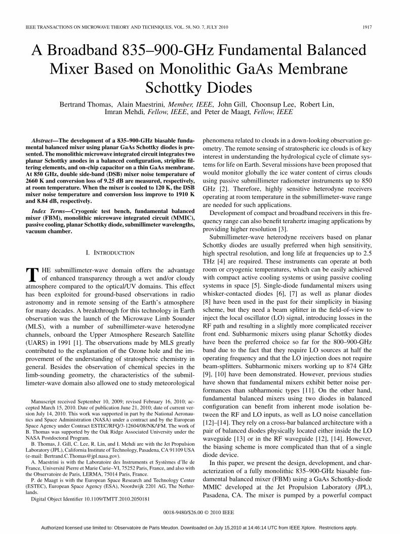
Fig. 1. View of the 835–900-GHz FBM circuit mounted inside the lower half of the mechanical block, including an MMIC mixer device (center) mounted withdc chip capacitor (top) and IF transformer (right), dc bias, ground and IF gold beam-leads, and diodes cell close-up (insert on the top left corner) including theon-chip MIM capacitor. The device is approximately 0.7 mm long.
III. 835–900-GHZ FBM TOPOLOGY AND ARCHITECTURE
The topology of the 835–900-GHz FBM is based on across-bar balanced architecture introduced earlier by [26]and subsequently used at higher frequencies [13], [14]. For thepresent design, both diodes are located inside the RF waveguidein a series configuration across the central suspended stripline,as illustrated in Fig. 1. The circuit is based on a thin GaAsmembrane and uses beamleads for connections and handling[27].
The Schottky contacts, defined using E-beam lithography,are connected to the circuit via air-bridges. The JPL MMICmembrane Schottky process described in [27] is speciallysuited for the realization of FBMs at these frequencies. Indeed,the thin membrane prevents excessive dielectric loading of thewaveguides and channels, and the beamleads allow for a precisegrounding, centering, and dc/IF connection of the MMIC to theblock and dc/IF circuits. The on-chip MIM capacitor allowsto dc bias the mixer with minimum RF/LO fields disturbance.Finally, the MMIC process reduces the uncertainties associatedwith handling and placing the device inside the block.
The LO signal is coupled via a bowtie -plane probe with in-tegrated dc/IF line to the diode. This transition is adapted froma previous design that uses an integrated dc bias line [28]. Thelength of the narrow line connecting the bowtie antenna is opti-mized to prevent any resonance in the desired LO band. Thebandwidth of this bowtie-type transition is also improved byadding narrow steps inside the LO waveguide, as demonstratedby [29]. A dc bias line on a metal–insulator–metal (MIM) capac-itor similar to [30] is used to bias the diodes in series while pro-viding an efficient IF, LO, and RF ground. The mixer block alsoincludes a diagonal feed-horn antenna [31] for the RF input cou-pling and a WR-1.2 LO input waveguide with UG-387 flange.The measured dc characteristics of the diode MMIC are consis-tent with the theoretically expected numbers described above.
External chip capacitors are used for the dc bias and furtherfiltering of any unwanted IF residue. The IF signal is output
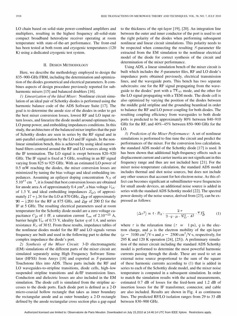
Fig. 2. View of the lower half of the mechanical split-block, showing fromleft to right the SMA-type dc glass bead, dc chip capacitors, the IF impedancetransformer, and the K-type IF glass bead.
through an IF impedance transformer to the K-type connector.The IF transformer circuit is designed to improve the voltagestanding wave ratio between the mixer and the external firstlow-noise amplifier (LNA) in the 2–11-GHz range. A view ofthe IF transformer mounted inside the lower half of the mechan-ical block is shown in Fig. 2. It consists of a meandering line tomatch from 200 to 50 in four-section impedance steps. Thecircuit is based on gold microstrip lines deposited on a 1.27-mm-thick aluminum–nitride substrate. This enables to keep returnlosses above 10 dB and insertion losses below 1 dB over a rel-atively broad bandwidth of 2–11 GHz. The dc bias chip capac-itors are connected with thermo-compressed bond wires to aSMA-type glass bead. An SMA flange launcher connector ismounted afterwards to the block. The IF circuit is connected toa K-type glass bead via a stripline stress relief contact1 insertedon the tip of the glass bead and silver-epoxy glued on the endingof the microstrip line section.
1Anritsu Corporation. [Online]. Available: http://www.anritsu.com.
Authorized licensed use limited to: Observatoire de Paris Meudon. Downloaded on July 15,2010 at 14:46:14 UTC from IEEE Xplore. Restrictions apply.
1920 IEEE TRANSACTIONS ON MICROWAVE THEORY AND TECHNIQUES, VOL. 58, NO. 7, JULY 2010
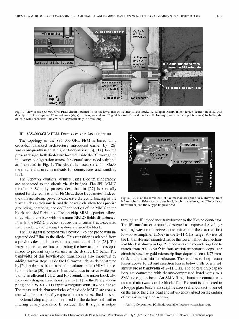
Fig. 3. Cryogenic mixer test setup, including the vacuum chamber (middle), a liquid nitrogen dewar, vacuum pump, and cryo-cooler (left-hand side), and externalelectronic system LO/IF/dc and control system (right-hand side). Details of the arrangement inside the test chamber include front-end multipliers/mixer, heatedcopper bracket mounting fixture, gold-plated chopper blade and motor, and two reference targets for hot and cold calibrations.
IV. CRYOGENIC TEST SETUP
The test bench shown in Fig. 3 allows for the characterizationof submillimeter-wave mixers and receivers in a vacuum envi-ronment and at temperatures compatible with passive cooling inspace, i.e., within the range 80–300 K.
It includes a cryogenic vacuum test chamber connected toan external vacuum mechanical and turbo pump, a cryo-cooler,and a custom-made liquid nitrogen LN dewar. The cali-bration system is located completely inside the test chamberand includes a room temperature load, a LN cooled load, adual-blade chopper, and vacuum stepper motor. This arrange-ment allows for direct -factor measurements without anyadditional corrections for atmospheric losses, added optics,and windows. The hot load is made of small tiles of TK-RAMmaterial (from Thomas Keating) and sitting on the bottom ofthe test chamber. The load is thermally strapped to the 295 Kwalls of the vacuum chamber. The cold load is made of MF116 Eccosorb material (from Emerson and Cuming) machinedinto pyramidal shapes and is connected via a thermal vacuumfeed-through to the external LN dewar. Hot and cold loads aremeasured at approximately 294 and 115 K, respectively, forroom-temperature measurements and 283 and 105 K, respec-tively, for 120-K measurements. Their temperature is constantlymonitored using temperature sensors and controller (Lakeshore330) and is very stable over a -factor measurement cycle(variation of less than 0.2 K).
The LO signal is provided by an Agilent -band source con-nected to an Agilent synthesizer and a set of power-combined
-band amplifier module that can output over 500 mW in thefrequency range 90–100 GHz located outside the test chamber.The -band LO signal is then coupled into the test chambervia a WR-10 waveguide vacuum feed-through and waveguideinto a powerful 300-GHz quad-chip tripler and 900-GHz dual-chip tripler that outputs over 1 mW at room temperature be-tween 840–900 GHz, and over 1.5 mW when cooled at 120 Kbetween 850–906 GHz [32]. The physical temperature of thefront-end elements is controlled to within 2 K of the targetvalue by external heat controlling system. The dc connection
between the mixer multipliers and the dc bias supplies outsidethe test chamber is done via SMA flexible cables and vacuumfeed-throughs. A 15-MHz dc low-pass filter is inserted betweenthe bias box and vacuum chamber to filter any unwanted EMpollution from the environment. A shielded 2-4-GHz dc-blockis inserted between the IF output connector of the test chamberand the IF processor in order to bias both mixer diodes in se-ries using the dc bias line. Insertion losses of 0.64 dB in averagebetween the output IF connector of the mixer and the input con-nector of the IF processor have been measured independentlyfrom 2 to 4 GHz at room temperature.
The 2–4-GHz IF processor outside the test chamber com-prises of input isolator, a 20-dB hybrid coupler, a low-noisepreamplifier, a 2–4-GHz filter, a low-cost amplifier, and a finalisolator. A 2–4-GHz noise source with an excess noise ratio of15.5 dB is connected to the coupled port of the 20-dB coupler.Biasing the noise source enables to change accurately the noisetemperature of the IF processor from 84.6 0.5 K (OFF state)to 191.8 1.1 K (ON state). The output of the IF processor isconnected to an Agilent average power sensor and power meterwith 0.001 dB of resolution. The independent full calibrationof the IF processor as well as the test procedure to retrieve theDSB mixer noise temperature and conversion losses from the
-factor measurement are detailed in [33].
V. MIXER MEASUREMENTS AND ANALYSIS
The measurement results including the DSB mixer noise tem-perature and DSB mixer conversion losses versus LO frequencyat both room temperature and 120 K are presented in Fig. 4.Predicted performances based on the designed procedure andparameters described in Section III) are also shown in the samefigure for comparison. For each frequency point, the receivernoise temperature is optimized using the bias voltage of bothtriplers and the 835–900-GHz mixer. Tuning of the triplers biasvoltage allows for adjusting the LO pump power and not overpump the mixer.
The dc bias tuning of the mixer allows for adjusting the mixercurrent in order to get optimum performance. Due to the high
Authorized licensed use limited to: Observatoire de Paris Meudon. Downloaded on July 15,2010 at 14:46:14 UTC from IEEE Xplore. Restrictions apply.
THOMAS et al.: BROADBAND 835–900-GHz FUNDAMENTAL BALANCED MIXER BASED ON MONOLITHIC GaAs MEMBRANE SCHOTTKY DIODES 1921
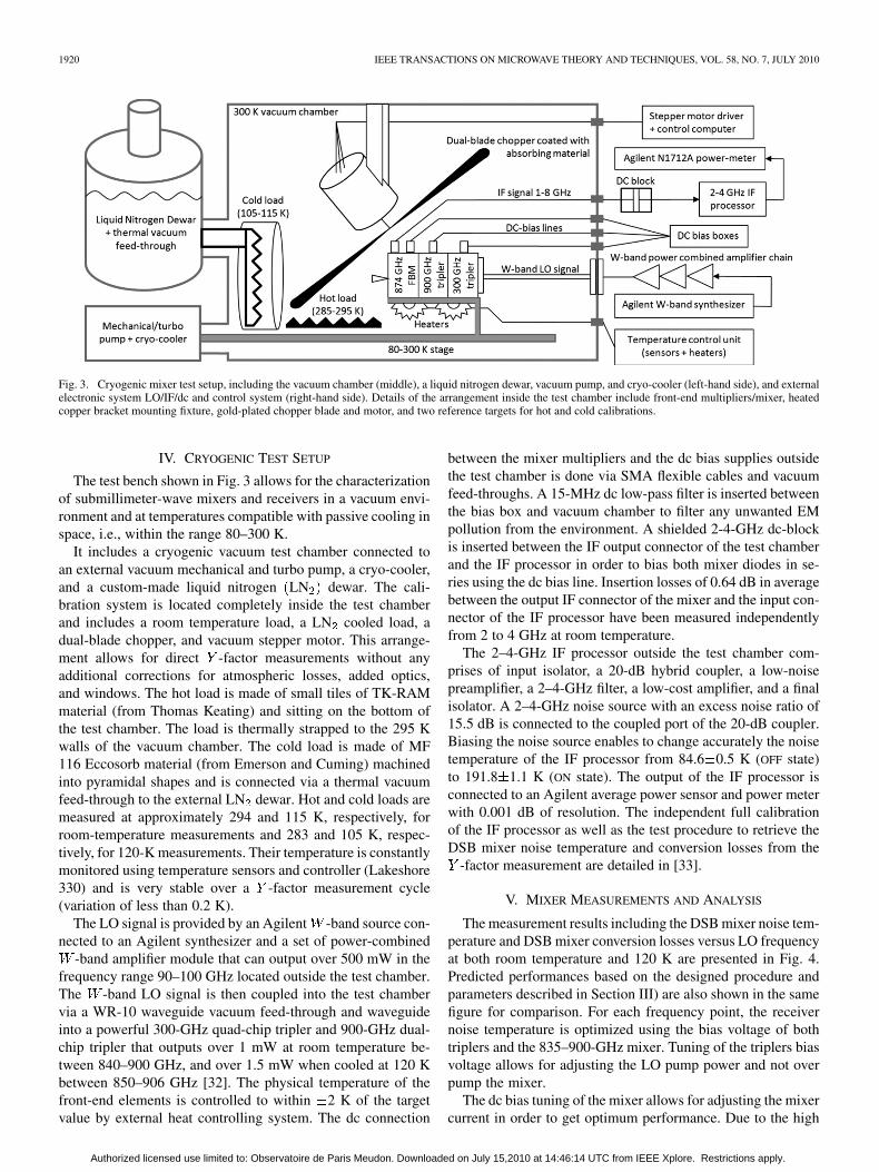
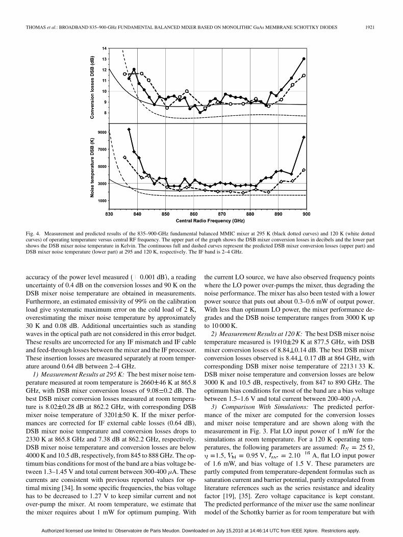
Fig. 4. Measurement and predicted results of the 835–900-GHz fundamental balanced MMIC mixer at 295 K (black dotted curves) and 120 K (white dottedcurves) of operating temperature versus central RF frequency. The upper part of the graph shows the DSB mixer conversion losses in decibels and the lower partshows the DSB mixer noise temperature in Kelvin. The continuous full and dashed curves represent the predicted DSB mixer conversion losses (upper part) andDSB mixer noise temperature (lower part) at 295 and 120 K, respectively. The IF band is 2–4 GHz.
accuracy of the power level measured 0.001 dB , a readinguncertainty of 0.4 dB on the conversion losses and 90 K on theDSB mixer noise temperature are obtained in measurements.Furthermore, an estimated emissivity of 99% on the calibrationload give systematic maximum error on the cold load of 2 K,overestimating the mixer noise temperature by approximately30 K and 0.08 dB. Additional uncertainties such as standingwaves in the optical path are not considered in this error budget.These results are uncorrected for any IF mismatch and IF cableand feed-through losses between the mixer and the IF processor.These insertion losses are measured separately at room temper-ature around 0.64 dB between 2–4 GHz.
1) Measurement Results at 295 K: The best mixer noise tem-perature measured at room temperature is 2660 46 K at 865.8GHz, with DSB mixer conversion losses of 9.08 0.2 dB. Thebest DSB mixer conversion losses measured at room tempera-ture is 8.02 0.28 dB at 862.2 GHz, with corresponding DSBmixer noise temperature of 3201 50 K. If the mixer perfor-mances are corrected for IF external cable losses (0.64 dB),DSB mixer noise temperature and conversion losses drops to2330 K at 865.8 GHz and 7.38 dB at 862.2 GHz, respectively.DSB mixer noise temperature and conversion losses are below4000 K and 10.5 dB, respectively, from 845 to 888 GHz. The op-timum bias conditions for most of the band are a bias voltage be-tween 1.3–1.45 V and total current between 300-400 A. Thesecurrents are consistent with previous reported values for op-timal mixing [34]. In some specific frequencies, the bias voltagehas to be decreased to 1.27 V to keep similar current and notover-pump the mixer. At room temperature, we estimate thatthe mixer requires about 1 mW for optimum pumping. With
the current LO source, we have also observed frequency pointswhere the LO power over-pumps the mixer, thus degrading thenoise performance. The mixer has also been tested with a lowerpower source that puts out about 0.3–0.6 mW of output power.With less than optimum LO power, the mixer performance de-grades and the DSB noise temperature ranges from 3000 K upto 10 000 K.
2) Measurement Results at 120 K: The best DSB mixer noisetemperature measured is 1910 29 K at 877.5 GHz, with DSBmixer conversion losses of 8.84 0.14 dB. The best DSB mixerconversion losses observed is 8.44 0.17 dB at 864 GHz, withcorresponding DSB mixer noise temperature of 2213 33 K.DSB mixer noise temperature and conversion losses are below3000 K and 10.5 dB, respectively, from 847 to 890 GHz. Theoptimum bias conditions for most of the band are a bias voltagebetween 1.5–1.6 V and total current between 200-400 A.
3) Comparison With Simulations: The predicted perfor-mance of the mixer are computed for the conversion lossesand mixer noise temperature and are shown along with themeasurement in Fig. 3. Flat LO input power of 1 mW for thesimulations at room temperature. For a 120 K operating tem-peratures, the following parameters are assumed: 25 ,
1.5, 0.95 V, 2.10 A, flat LO input powerof 1.6 mW, and bias voltage of 1.5 V. These parameters arepartly computed from temperature-dependent formulas such assaturation current and barrier potential, partly extrapolated fromliterature references such as the series resistance and idealityfactor [19], [35]. Zero voltage capacitance is kept constant.The predicted performance of the mixer use the same nonlinearmodel of the Schottky barrier as for room temperature but with
Authorized licensed use limited to: Observatoire de Paris Meudon. Downloaded on July 15,2010 at 14:46:14 UTC from IEEE Xplore. Restrictions apply.
1922 IEEE TRANSACTIONS ON MICROWAVE THEORY AND TECHNIQUES, VOL. 58, NO. 7, JULY 2010
the modified electrical parameters listed above. As illustratedin Fig. 4, the simulations agree globally to within 1 dB of themeasurements for both the DSB conversion losses and DSBnoise figure at room temperature between 844–888 GHz. At120 K, the simulations predict a drop in mixer noise temper-ature of approximately 600 K, which is comparable to 775 Kin average for the measurements. The simulated DSB mixerconversion losses are consistent with the measurements at roomtemperature and 1 dB lower than expected at 120 K. This canbe partly explained by the fact that the electrical characteristicsof the Schottky diodes considered during the simulations areonly estimated and have not been measured at this temperature.Uncertainties in the series resistance, ideality factor, and satu-ration current might lead to an optimistic value of the simulatedconversion losses. Moreover, the device performance based onsimulation show a broader operating bandwidth than what ismeasured. Below 845 GHz, this discrepancy can be explainedby the fact that a constant LO power is considered in simulationfor all frequencies, whereas a decrease in coupling efficiencyof the mixer (refer to Section III) combined to a monotonicdecrease in power available from the LO source adds up tostarve the mixer in pump power. Above 890 GHz, additionalsimulations have shown that a shift of 10 m of the circuitinside the RF waveguide would lead to a degradation of theperformances at the high end of the designed band. Machiningtolerances of the block added to mounting tolerances insidethe block of the chip can be estimated to at least 10 m and,therefore, could explain the degradation of the performancesabove 890 GHz.
4) Comparison With an 874-GHz Subharmonic Mixer: An874-GHz MMIC subharmonic mixer developed previouslyusing the same process give DSB mixer noise temperatures ofapproximately 4000 K and DSB conversion losses of 12 dBat room temperature (deduced from [21]). However, a directcomparison with this device cannot be made as such due to thefact that the subharmonic and fundamental MMIC devices havedifferent doping densities and that the subharmonic mixer doesnot have any IF matching circuit included inside the block. Thepower consumption is significantly higher for the FBM channel(approximately 5 W) compared with the subharmonic mixerchannel (approximately 2 W). This mainly due to the amountof power that has to be generated at the -band (500 mW forthe FBM instead of 150 mW for the subharmonic mixor) usingpower-combined amplifiers. The multipliers can be self-biasedand should not influence significantly the total power budget.It is interesting to notice that, due to the amount of LO poweravailable, the subharmonic mixer can be operated bias-lesswhereas the FBM needs to be biased externally and cannot beself-biased, adding the power consumption of a bias board tothe total power consumption.
The FBM performance obtained in this study is similar to theperformance reported at a single frequency point on the bestwhisker-contacted corner-cubes single-ended mixer [6].
VI. CONCLUSION
A broadband FBM working in the 835–900-GHz rangebased on membrane Schottky diodes has been demonstrated.
The mixer provides superior performance compared with sub-harmonic mixers in a similar frequency range. The LO sourcefor the mixer is based on a multiplier chain and has shown toprovide sufficient power to pump the mixer. This represents thefirst demonstration of a compact broadband room-temperaturereceiver in this frequency range with a balanced mixer design.Moreover, it is demonstrated that, by cooling the mixer to120 K, a 2-dB improvement can be achieved in the receiverperformance. The successful demonstration of this designmethodology along with the availability of high-power sourcesin the 600–1200-GHz range now enable development of highlysensitive heterodyne receivers at room temperature in thisfrequency range.
ACKNOWLEDGMENT
The authors would like to thank Dr. P. Siegel, JPL, Pasadena,CA, for his continued support, encouragement, and discussionsregarding terahertz technology. The authors would also like toacknowledge Dr. Boussaha, LERMA, Paris, France, for his helpwith dicing of the IF circuits and SAP-France for the high-quality block manufacturing. The work was carried out at theJPL, California Institute of Technology, under a contract withNASA, and at Observatoire de Paris.
REFERENCES
[1] F. T. Barath et al., “The upper atmosphere research satellite MicrowaveLimb Sounder instrument,” J. Geophys. Res. Atmos., vol. 98, no. D6,pp. 10,751–10,762, Jun. 1993.
[2] S. A. Buehler, “CIWSIR: A proposed ESA submillimetre mission tomeasure cloud ice,” in Proc. 5th ESA Workshop MM-Wave Tech Appl.,Noordwijk, The Netherlands, May 18–20, 2009, pp. 547–554.
[3] K. B. Cooper, R. J. Dengler, N. Llombart, T. Bryllert, G. Chattopad-hyay, E. Schlecht, J. Gill, C. Lee, A. Skalare, I. Mehdi, and P. Siegel,“Penetrating 3-D imaging at 4- and 25-m range using a submillimeter-wave radar,” IEEE Trans. Microw. Theory Tech., vol. 56, no. 12, pp.2771–2778, Dec. 2008.
[4] P. H. Siegel, R. P. Smith, M. C. Gaidis, and S. C. Martin, “2.5-THzGaAs monolithic membrane-diode mixer,” IEEE Trans. Microw.Theory Tech., vol. 47, no. 5, pp. 596–604, May 1999.
[5] A. R. Kerr, “Low-noise room-temperature and cryogenic mixers for80–120 GHz,” IEEE Trans. Microw. Theory Tech., vol. MTT-23, no.10, pp. 781–787, Oct. 1975.
[6] H. P. Roeser, H. W. Huebers, T. W. Crowe, and W. C. B. Peatman,“Nanostructure GaAs Schottky diodes for far-infrared heterodyne re-ceivers,” Infrared Phys. Technolol., vol. 35, no. 2–3, pp. 451–462, Mar./Apr. 1994.
[7] T. Suzuki, T. Yasui, H. Fujishima, T. Nozokido, M. Araki, O. Boric-Lubecke, V. M. Lubecke, and K. Mizuno, “Reduced low-frequencynoise Schottky barrier diodes for terahertz applications,” IEEE Trans.Microw. Theory Tech., vol. 47, no. 9, pp. 1649–1655, Sep. 1999.
[8] J. Hesler, W. R. Hall, T. W. Crowe, R. M. Weikle, B. S. Deaver, Jr, R.F. Bradley, and S.-K. Pan, “Fix-tuned submillimeter wavelength wave-guide mixers using planar Schottky-barrier diodes,” IEEE Trans. Mi-crow. Theory Tech., vol. 45, no. 5, pp. 653–658, May 1997.
[9] E. Schlecht, J. Gill, R. Dengler, R. Lin, R. Tsang, and I. Mehdi,“A unique 520–590 GHz biased subharmonically-pumped Schottkymixer,” IEEE Microw. Wireless Compon. Lett., vol. 17, no. 12, pp.879–881, Dec. 2007.
[10] B. Thomas, A. Maestrini, D. Matheson, I. Mehdi, and P. de Maagt,“Design of an 874 GHz biasable sub-harmonic mixer based on MMICmembrane planar Schottky diodes,” in Proc. 33rd Int. Conf. IR, Mil-limeter Terahertz Waves, Pasadena, CA, Sep. 2008, Paper W4G3.1437.
[11] A. R. Kerr, “Noise and loss in balanced and subharmonically pumpedmixers: Part II-application,” IEEE Trans. Microw. Theory Tech., vol.MTT-27, no. 12, pp. 944–950, Dec. 1979.
[12] J. A. Wells, N. J. Cronin, and P. H. Reece, “Rugged 94 GHz crossbarbalanced mixer,” Proc. Inst. Elect. Eng., vol. 137, no. 4, pt. H, pp.235–237, Aug. 1990.
Authorized licensed use limited to: Observatoire de Paris Meudon. Downloaded on July 15,2010 at 14:46:14 UTC from IEEE Xplore. Restrictions apply.

THOMAS et al.: BROADBAND 835–900-GHz FUNDAMENTAL BALANCED MIXER BASED ON MONOLITHIC GaAs MEMBRANE SCHOTTKY DIODES 1923
[13] E. Schlecht, J. Gill, R. Dengler, R. Lin, R. Tsang, and I. Mehdi, “Firstwideband 520–590 GHz balanced fundamental Schottky mixer,” inProc. 18th Int. Symp. Space Terahertz Technol., Pasadena, CA, Mar.2007, 296 pp.
[14] N. R. Erickson and T. M. Goyette, “Terahertz Schottky-diode balancedmixers,” in Proc. SPIE Conf., Feb. 2009, vol. 7215, pp. 1–5.
[15] B. Thomas, A. Maestrini, and G. Beaudin, “A low-noise fixed-tuned300–360-GHz sub-harmonic mixer using planar Schottky diodes,”IEEE Microw. Wireless Compon. Lett., vol. 15, no. 12, pp. 865–867,Dec. 2005.
[16] D. W. Porterfield, T. W. Crowe, R. F. Bradley, and N. R. Erickson, “Ahigh-power fixed-tuned millimeter-wave balanced frequency doubler,”IEEE Trans. Microw. Theory Tech., vol. 47, no. 4, pp. 419–425, Apr.1999.
[17] “Advanced Design System,” Agilent Technol., Palo Alto, CA, 2009.[18] “High Frequency Simulation Software,” Ansoft Corporation, Pitts-
burgh, PA, V11.2.[19] A. Maestrini, J. S. Ward, J. J. Gill, H. S. Javadi, E. Schlecht, C. Tripon-
Canseliet, G. Chattopadhyay, and I. Mehdi, “A 540–640-GHz high-frequency four-anode frequency tripler,” IEEE Trans. Microw. TheoryTech., vol. 53, no. 9, pp. 2835–2843, Sep. 2005.
[20] B. Thomas, “Etude et réalisation d’une tête de réception hétérodyneen ondes sub-millimétriques pour l’étude des atmosphères et surfacesde planètes” Ph.D. dissertation, Lab. d’Etude du Rayonnement et de laMat. en Astrophys., Observatoire de Paris, Paris, France, 2004 [On-line]. Available: http://hal.archivesouvertes.fr/docs/00/39/22/39/PDF/These_doctorat_Thomas_2004.pdf
[21] B. Thomas, A. Maestrini, J. Ward, E. Schlecht, J. Gill, C. Lee, R.Lin, and I. Mehdi, “Terahertz cooled sub-harmonic Schottky mixers forplanetary atmospheres,” in Proc. 5th ESA Workshop Millimetre WaveTechnol. Appl., Noordwijk, The Netherlands, May 2009, pp. 101–108.
[22] B. Thomas, A. Maestrini, J. C. Orlhac, J. Goutoule, and G. Beaudin,“Numerical analysis of a 330 GHz sub-harmonic mixer with planarSchottky diodes,” in Proc. 3rd ESA Workshop Millimetre-WaveTechnol. Tech., Espoo, Finland, May 2003, pp. P1–18.
[23] T. W. Crowe and R. J. Mattauch, “Analysis and optimization of mil-limeter- and submillimeter-wavelength mixer diodes,” IEEE Trans. Mi-crow. Theory Tech., vol. MTT-35, no. 2, pp. 159–168, Feb. 1987.
[24] J. Heiermann and H.-P. Roeser, “Semiclassical description of Schottkydiode mixer properties at THz frequenices,” in Proc. 16th Int. Symp.Space Terahertz Technol., Göteborg, Sweden, May 2005, pp. 483–485.
[25] G. E. Stillman and C. M. Wolfe, “Electrical characterization of epitaxiallayers,” Thin Solid Films, vol. 31, pp. 69–88, 1976.
[26] L. T. Yuan, “Design and performance analysis of an octave bandwidthwaveguide mixer,” IEEE Trans. Microw. Theory Tech., vol. MTT-25,no. 12, pp. 1048–1054, Dec. 1977.
[27] S. Martin, B. Nakamura, A. Fung, P. Smith, J. Bruston, A. Maestrini,F. Maiwald, P. Siegel, E. Schlecht, and I. Mehdi, “Fabrication of 200to 2700 GHz multiplier devices using GaAs and metal membranes,” inIEEE MTT-S Int. Microw. Symp. Dig., 2001, vol. 3, pp. 1641–1644.
[28] C. Risacher, V. Vassilev, A. Pavolotsky, and V. Belitsky, “Wave-guide-to-microstrip transition with integrated bias-T,” IEEE Microw.Wireless Compon. Lett., vol. 13, pp. 262–264, 2003.
[29] J. W. Kooi, G. Chattopadhyay, S. Withington, F. Rice, J. Zmuidzinas,C. Walker, and G. Yassin, “A full-height waveguide to thin-film tran-sition with exceptional RF bandwidth and coupling efficiency,” Int. J.Infrared Millimeter Waves, vol. 24, no. 3, pp. 261–284, Mar. 2003.
[30] J. Bruston, A. Maestrini, D. Pukala, S. Martin, B. Nakamura, and I.Mehdi, “A 1.2 THz planar tripler using GaAs membrane based chips,”in Proc. 12th Int. Symp. Space Terahertz Technol., San Diego, CA, Feb.2001, pp. 310–319.
[31] J. Johansson and N. D. Whyborn, “The diagonal horn as a submil-limeter wave antenna,” IEEE Trans. Microw. Theory Tech., vol. 40, no.5, pp. 795–800, May 1992.
[32] A. Maestrini, J. S. Ward, J. J. Gill, C. Lee, B. Thomas, R. H. Lin, G.Chattopadhyay, and I. Mehdi, “A 0.9 THz frequency multiplied sourcewith milliwatts of power,” IEEE Trans. Microw. Theory Tech., to bepublished.
[33] J. Treuttel, B. Thomas, A. Maestrini, H. Wang, B. Alderman, J. V. Siles,S. Davies, and T. Narhi, “A 380 GHz sub-harmonic mixer using MMICfoundry based Schottky diodes transferred onto quartz substrate,” inProc. 20th Int. Symp. Space Terahertz Technol., Charlottesville, VA,Apr. 2009, pp. 251–254.
[34] H. P. Roeser, R. U. Titz, G. W. Schwaab, and M. F. Kimmitt, “Cur-rent-frequency characteristics of submicrometer GaAs Schottky barrierdiodes with femtofarad capacitance,” J. Appl. Phys., vol. 72, no. 7, pp.3194–3197, Oct. 1992.
[35] P. H. Siegel, I. Mehdi, and J. East, “Improved millimeter-wave mixerperformance analysis at cryogenic temperatures,” IEEE Microw.Guided Wave Lett., vol. 1, no. 6, pp. 129–131, Jun. 1991.
Bertrand Thomas received the M.Sc. degree inradio-communication and microwave engineeringjointly from ESIEE-Paris, Paris, France, and Uni-versité Marne-la-Vallée, Marne-la-Vallée, France, in1999, and the Ph.D. degree in astrophysics and spaceinstrumentation jointly from University Paris-VI,Paris, France, and Observatoire de Paris, Paris,France, in 2004.
From 1999 to 2001, he was with the ReceiverGroup, IRAM 30-m Radio-Relescope, Granada,Spain. From 2001 to 2004, he was with the LERMA
Department, Observatoire de Paris, Paris, France. From 2005 to 2008, he wasa Research Engineer with the Rutherford Appleton Laboratory, Oxfordshire,U.K. In 2008, he joined the Submillimeter-Wave Advanced Technology Group,Jet Propulsion Laboratory (JPL), California Institute of Technology, Pasadena,as a National Aeronautics and Space Administration (NASA) PostdoctoralProgram Fellow. His current research interests are the design and developmentof semiconductor devices for terahertz heterodyne receivers for planetaryscience and astrophysics.
Dr. Thomas was the recipient of the 2009 JPL Outstanding Postdoctoral Re-search Award from NASA.
Alain Maestrini (M’05) received the M.S. degree intelecommunications and electrical engineering fromthe ENST de Bretagne, Bretagne, France, in 1993,and the Ph.D. degree in electronics jointly fromthe Université de Bretagne Occidentale, Bretagne,France, and the Observatoire de Paris, Paris, France,in 1999.
From 1993 to 1995, he was an Engineer with theReceiver Group, IRAM 30-m Telescope, Granada,Spain. In 1999, he joined the Submillimeter-WaveAdvanced Technology Group, Jet Propulsion Lab-
oratory (JPL), California Institute of Technology, Pasadena, to work onsolid-sate terahertz LO development for the heterodyne instrument of theHerschel Space Observatory. He returned to the Observatoire de Paris in 2002and in 2003 joined the Laboratoire des Instruments et Systèmes d’Ile de France,Université Pierre et Marie Curie, Paris, as an Assistant Professor in electronicsand microwaves. Since January 2008, he has been an Associate of LERMA,Observatoire de Paris, and a Technical Advisor for JPL. His current researchinterests are in the design of integrated millimeter- and submillimeter-waveelectronics for radio astronomy and planetary science.
Dr. Maestrini was the recipient of the Arago Prize from the French Academyof Science in 2009.
John Gill received the B.S. and M.S. degrees inmechanical engineering and Ph.D. degree microelec-tromechanical systems (MEMS) from the Universityof California at Los Angeles (UCLA), in 1997 and2001, respectively.
From 1997 to 1998, he was with the Jet Propul-sion Laboratory (JPL), California Institute of Tech-nology, Pasadena, where he was involved in devel-oping the quantum-well infrared photodetector. Cur-rently, he is back with JPL working on developing mi-crowave devices. In 2001, he became involved with
Herschel, a joint flight project with the European Space Agency (ESA), wherehe is leading the high-frequency cutting-edge multiplier and mixer device devel-opment effort. His research interests include design, fabrication, and characteri-zation of microelectronic devices using conventional integrated circuit, MEMS,and nanoelectromechanical systems (NEMS) technologies for space and indus-trial applications.
Authorized licensed use limited to: Observatoire de Paris Meudon. Downloaded on July 15,2010 at 14:46:14 UTC from IEEE Xplore. Restrictions apply.
1924 IEEE TRANSACTIONS ON MICROWAVE THEORY AND TECHNIQUES, VOL. 58, NO. 7, JULY 2010
Choonsup Lee received the B.S. degree in electricalengineering from Kyungpook National University,Daegu, Korea, in 1996, and the M.S. and Ph.D. de-grees in electrical engineering and computer sciencefrom the Korea Advanced Institute of Science andTechnology (KAIST), Seoul, Korea, in 1998 and2002, respectively.
He is currently a Member of the Technical Staffwith the Jet Propulsion Laboratory (JPL), CaliforniaInstitute of Technology, Pasadena. He has extensiveexperiences in the design and characterization of mi-
croelectromechanical systems/nano devices. He is currently working on GaAs-based frequency sources and mixers in the terahertz region. He has authoredor coauthored 17 international journal papers and 32 international conferencepapers.
Robert Lin received the B.S. and M.S. degrees inelectrical engineering from the California Instituteof Technology, Pasadena, in 1997 and 2002, respec-tively.
Since 1997, he has been a part of the Submil-limeter-Wave Advanced Technology Group, JetPropulsion Laboratory (JPL), California Institute ofTechnology, Pasadena, CA, where he has helped toassemble, build, and test submillimeter-wave andterahertz amplifiers, multipliers, and mixers for plan-etary, astrophysics, and earth-based applications.
Imran Mehdi (S’85–M’91–SM’05–F’10) receivedthe three-year Certificate in Letters and Science fromCalvin College, Grand Rapids, MI, in 1983, and theB.S.E.E., M.S.E.E., and Ph.D. (E.E.) degrees fromthe University of Michigan at Ann Arbor, in 1984,1985, and 1990, respectively.
In 1990, he joined the Jet Propulsion Laboratory(JPL), California Institute of Technology, Pasadena,where his responsibilities included the design andfabrication of low-parasitic planar Schottky diodesfor mixers in the terahertz range. Since 1999, he
has led the effort of developing broadband solid-state sources from 200 to2500 GHz for the heterodyne instrument on the Herschel Space Observatory,a cornerstone European Space Agency (ESA) mission. Currently, he is a Prin-cipal Member of Engineering Staff with JPL and is responsible for developingterahertz technology for future National Aeronautics and Space Administration(NASA) missions. His interests include millimeter- and submillimeter-wavedevices, high-frequency instrumentation, and heterodyne receiver systems.
Peter de Maagt (S’88–M’88–SM’02–F’08) wasborn in Pauluspolder, The Netherlands, in 1964.He received the M.Sc. and Ph.D. degrees from theEindhoven University of Technology, Eindhoven,The Netherlands, in 1988 and 1992, respectively,both in electrical engineering.
From 1992 to 1993, he was a Station Managerand Scientist with an INTELSAT propagationproject, Surabaya, Indonesia. He is currently withthe European Space Research and TechnologyCentre (ESTEC), European Space Agency (ESA),
Noordwijk, The Netherlands. His research interests are in the area of millimeterand submillimeter-wave reflector and planar integrated antennas, quasi-optics,electromagnetic-bandgap antennas, and millimeter- and submillimeter-wavecomponents.
Dr. de Maagt serves as an associate editor for the IEEE TRANSACTION ON
ANTENNAS AND PROPAGATION and was coguest editor of the November 2007Special Issue on Optical and Terahertz Antenna Technology. He was corecipientof the H. A. Wheeler Award of the IEEE Antennas and Propagation Society(IEEE AP-S) for the Best Applications Paper of 2001 and 2008. He was grantedan ESA Award for Innovation in 2002. He was corecipient of Best Paper Awardsat the Loughborough Antennas Propagation Conference (LAPC) 2006 and theInternational Workshop on Antenna Technology IWAT) 2007.
Authorized licensed use limited to: Observatoire de Paris Meudon. Downloaded on July 15,2010 at 14:46:14 UTC from IEEE Xplore. Restrictions apply.