ieee transactions on power electronics, · pdf fileneath et al.: optimal pid controller for a...
TRANSCRIPT

IEEE TRANSACTIONS ON POWER ELECTRONICS, VOL. 29, NO. 3, MARCH 2014 1523
An Optimal PID Controller for a BidirectionalInductive Power Transfer System Using
Multiobjective Genetic AlgorithmMichael J. Neath, Student Member, IEEE, Akshya K. Swain, Member, IEEE,
Udaya K. Madawala, Senior Member, IEEE, and Duleepa J. Thrimawithana, Member, IEEE
Abstract—Bidirectional inductive power transfer (IPT) systemsare suitable for applications that require wireless and two-waypower transfer. However, these systems are high-order resonantnetworks in nature and, hence, design and implementation of anoptimum proportional–integral–derivative (PID) controller usingvarious conventional methods is an onerous exercise. Further, thedesign of a PID controller, meeting various and demanding spec-ifications, is a multiobjective problem and direct optimization ofthe PID gains often lead to a nonconvex problem. To overcomethe difficulties associated with the traditional PID tuning methods,this paper, therefore, proposes a derivative-free optimization tech-nique, based on genetic algorithm (GA), to determine the optimalparameters of PID controllers used in bidirectional IPT systems.The GA determines the optimal gains at a reasonable computa-tional cost and often does not get trapped in a local optimum. Theperformance of the GA-tuned controller is investigated using sev-eral objective functions and under various operating conditions incomparison to other traditional tuning methods. It was observedthat the performance of the GA-based PID controller is dependenton the nature of the objective function and therefore an objectivefunction, which is a weighted combination of rise time, settlingtime, and peak overshoot, is used in determining the parametersof the PID controller using multiobjective GA. Simulated and ex-perimental results of a 1-kW prototype bidirectional IPT systemare presented to demonstrate the effectiveness of the GA-tunedcontroller as well as to show that gain selection through multiob-jective GA using the weighted objective function yields the bestperformance of the PID controller.
Index Terms—Contactless power transfer, electric vehicles(EVs), inductive power transmission.
I. INTRODUCTION
INDUCTIVE power transfer (IPT) technology is now rec-ognized as an efficient means of transferring power from
one system to another “wirelessly or with no physical con-tacts.” This technology has the ability to operate in hostile en-vironments being unaffected by dirt and moisture and has now
Manuscript received December 23, 2012; revised March 15, 2013 and May7, 2013; accepted May 8, 2013. Date of current version September 18, 2013.Recommended for publication by Associate Editor J.-i. Itoh.
The authors are with the Department of Electrical and Computer Engineering,The University of Auckland, Auckland-1142, New Zealand (e-mail: [email protected]; [email protected]; [email protected];[email protected]).
Color versions of one or more of the figures in this paper are available onlineat http://ieeexplore.ieee.org.
Digital Object Identifier 10.1109/TPEL.2013.2262953
evolved into a stage where it can transfer power at efficiencies ashigh as ∼94%. Consequently, IPT systems are used in numer-ous applications, ranging from low-power biomedical implantsup to high-power materials handling systems [1]–[3]. Recently,the focus has been on developing IPT-based systems for wire-less charging of electric vehicles (EVs), which is more conve-nient and more tamper proof than conventional plug-in or hard-wired chargers. Furthermore, bidirectional IPT systems havealso been proposed and developed for applications that requiretwo-way power flow. Vehicle-to-grid (V2G) or G2V is a primeexample [4]–[7].
Usually, power-handling capability of IPT systems is im-proved by providing series, parallel, or a combination of seriesand parallel compensation for coil reactances [8]–[10]. As aconsequence, these systems invariably become high-order res-onant networks, which are complex in nature and are difficultto both design and control, given that the frequency of oper-ation is in the range of 10–50 kHz [11], [12]. Power flow inIPT systems can either be unidirectional or bidirectional but,irrespective of the direction of power flow, the system gener-ally requires two separate controllers, which are dedicated tocontrol the converters on each side of the system. Each con-troller regulates either the voltage or current, produced by itsconverter, to control the power flow. To keep switching lossesto a minimum, the voltage and current are preferably controlledthrough phase modulation. In contrast to unidirectional systems,bidirectional IPT systems are even higher order resonant net-works and more complex. The majority of these systems havebeen designed in the past using relatively simple steady-statemodels [13]–[16]. A dynamic state-space model for bidirec-tional IPT systems has recently been proposed and validated,and analysis has also been presented to show that decentralizedor separate controllers can be used to control the power flow inbidirectional IPT systems [17]. Although proportional–integral(PI) and proportional–integral–derivative (PID) controllers havebeen proposed and implemented to regulate the power flow inbidirectional IPT systems, it has only been for the purpose ofverifying a model or particular control strategy [10], [19], [20].As such, no attempt has been made to optimize the controllerdesign in relation to achieving the best possible dynamic per-formance of a bidirectional IPT system and this paper addressesthis need by proposing a controller optimization technique.
Various tuning rules have been proposed in the past to deter-mine parameters of PID controllers. The most popular amongthem is the Ziegler–Nichols (ZN) ultimate-cycle tuning method
0885-8993 © 2013 IEEE

1524 IEEE TRANSACTIONS ON POWER ELECTRONICS, VOL. 29, NO. 3, MARCH 2014
[20]. Although these methods perform well for lower orderprocesses, they often result in suboptimal performance, partic-ularly for higher order and nonlinear systems. For example, theZN method may cause high overshoots, large oscillations, andlonger settling times for higher order systems [21]. The bidi-rectional IPT system, being a higher order resonant network,falls into this category and the task of tuning PID gains forthis system is, therefore, a major challenge. One of the mostefficient methods of tuning PID parameters for such systems isthrough direct optimization, which often requires a solution to anonconvex problem. Various other methods such as refined ZNand pole placement [20], [22] have also been proposed to obtainthe optimum PID parameters. Majority of tuning methods usedfor higher order systems are based on model reduction tech-niques. However, these techniques along with direct optimiza-tion are not appropriate for bidirectional IPT systems, as IPTsystems are composed of high-order resonant circuits and oper-ated near the resonant frequency. Controllers designed using allthese techniques have poor performance and are not appropriatefor optimally controlling bidirectional IPT systems. An alter-nate approach to optimize the parameters is to use gradient-freeoptimization methods such as genetic algorithms (GAs), evo-lutionary computation, particle swarm optimization, etc. [23].These methods are simple to apply and can readily incorporatepractical meaningful performance characteristics into the PIDcontroller design and are not affected by the high-order natureof the system and fitness function.
This paper, therefore, proposes a GA to tune the parametersof a PID controller taking various objectives (fitness) functionsinto consideration, to achieve a controller with optimal perfor-mance. Since the chosen performance criterion to control poweris often a weighted combination of various performance charac-teristics such as rise time, settling time, percentage over-shootand integral of error squared, the PID parameter optimizationproblem is formulated in a multiobjective optimization frame-work and solved using a GA. Simulated performance of the pro-posed GA-based PID controller is compared with some of thewell-known tuning methods to investigate the optimal responseand the best balance between performance and robustness. Fi-nally, measured results of a 1-kW prototype bidirectional IPTsystem, implemented with a GA-based PID controller, whichuses a multiobjective fitness function, are presented to demon-strate the validity, performance and robustness of the optimumcontroller design.
II. BIDIRECTIONAL IPT SYSTEM
Fig. 1 shows a typical bidirectional IPT system, consisting ofa primary and a secondary side. The secondary circuit, whichreceives power from the primary through an air gap, is typicallyreferred to as the pickup. The primary and the pickup use iden-tical electronic circuitry, comprising a converter, an inductor–capacitor–inductor (LCL) resonant network with a series capac-itor and a dedicated controller. The controllers are independentof each other and operate the converters on both sides to regulatethe power flow across the air gap. The primary controller oper-ates the primary-side converter, which is connected to the LCL
Fig. 1. Typical bidirectional IPT system.
resonate network to produce a constant sinusoidal current at adesired frequency f0 in the primary winding, represented by thecoil Lpt . This primary winding is commonly referred to as theprimary track or the primary pad in IPT applications. The LCLcircuits on both sides of the system are tuned to the frequencyof track current ipt generated by the converter on the primaryside. In a bidirectional IPT system, the magnitude and/or phaseangle of the voltage vector produced by the pickup convertercan be controlled with respect to the voltage vector produced bythe primary converter to regulate the magnitude and directionof power flow, as described later.
Assume that the primary-side converter of the bidirectionalIPT system, shown in Fig. 1, produces a reference sinusoidalvoltage vpi∠0 at an angular frequency ω, and the track currentipt is held constant by the primary-side controller. Since theinductor Lpt is magnetically coupled to the secondary or thepickup coil Lst , a voltage is induced across Lst due to ipt . Theinduced voltage vsr in the pickup coil can be given by
vsr = jωMipt (1)
where M represents the mutual inductance between the wind-ings Lpt and Lst and can be given by
M = k√
LptLst (2)
where k is the coupling coefficient of the system, which typicallyis in the range of 0.1–0.3. As such, the coupling between theprimary and secondary of an IPT system is significantly less thanthat of a traditional transformer or an induction motor, whichhave coupling coefficients greater than 0.95.
The pickup may be operated as a source or a sink by thecontroller and, despite the mode of operation, the voltage vpr
reflected onto the track can be expressed by [6]
vpr = jωMist . (3)
If the LCL circuits on both primary and pickup sides are tunedto the angular frequency ω of the current then [6]
ω2 =1
L′piCpt
=1
LptCpt=
1L′
siCst=
1LstCst
. (4)
This implies that L′pi = Lpt and L′
si = Lst , where L′pi and
L′si are defined as
L′pi = Lpi −
1ωCpi
(5)
L′si = Lsi −
1ωCsi
. (6)
NEATH et al.: OPTIMAL PID CONTROLLER FOR A BIDIRECTIONAL INDUCTIVE POWER TRANSFER SYSTEM 1525
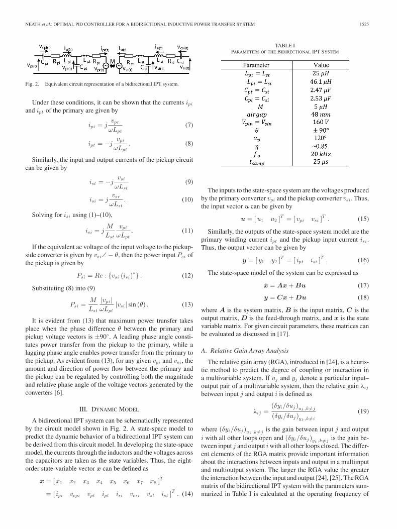
Fig. 2. Equivalent circuit representation of a bidirectional IPT system.
Under these conditions, it can be shown that the currents ipi
and ipt of the primary are given by
ipi = jvpr
ωLpt(7)
ipt = −jvpi
ωLpt. (8)
Similarly, the input and output currents of the pickup circuitcan be given by
ist = −jvsi
ωLst(9)
isi = jvsr
ωLst. (10)
Solving for isi using (1)–(10),
isi = jM
Lst
vpi
ωLpt. (11)
If the equivalent ac voltage of the input voltage to the pickup-side converter is given by vsi∠ − θ, then the power input Psi ofthe pickup is given by
Psi = Re : {vsi (isi)∗} . (12)
Substituting (8) into (9)
Psi =M
Lst
|vpi |ωLpt
|vsi | sin (θ) . (13)
It is evident from (13) that maximum power transfer takesplace when the phase difference θ between the primary andpickup voltage vectors is ±90◦. A leading phase angle consti-tutes power transfer from the pickup to the primary, while alagging phase angle enables power transfer from the primary tothe pickup. As evident from (13), for any given vpi and vsi , theamount and direction of power flow between the primary andthe pickup can be regulated by controlling both the magnitudeand relative phase angle of the voltage vectors generated by theconverters [6].
III. DYNAMIC MODEL
A bidirectional IPT system can be schematically representedby the circuit model shown in Fig. 2. A state-space model topredict the dynamic behavior of a bidirectional IPT system canbe derived from this circuit model. In developing the state-spacemodel, the currents through the inductors and the voltages acrossthe capacitors are taken as the state variables. Thus, the eight-order state-variable vector x can be defined as
x = [x1 x2 x3 x4 x5 x6 x7 x8 ]T
= [ ipi vcpi vpt ipt isi vcsi vst ist ]T . (14)
TABLE IPARAMETERS OF THE BIDIRECTIONAL IPT SYSTEM
The inputs to the state-space system are the voltages producedby the primary converter vpi and the pickup converter vsi . Thus,the input vector u can be given by
u = [u1 u2 ]T = [ vpi vsi ]T . (15)
Similarly, the outputs of the state-space system model are theprimary winding current ipt and the pickup input current isi .Thus, the output vector can be given by
y = [ y1 y2 ]T = [ ipt isi ]T . (16)
The state-space model of the system can be expressed as
x = Ax + Bu (17)
y = Cx + Du (18)
where A is the system matrix, B is the input matrix, C is theoutput matrix, D is the feed-through matrix, and x is the statevariable matrix. For given circuit parameters, these matrices canbe evaluated as discussed in [17].
A. Relative Gain Array Analysis
The relative gain array (RGA), introduced in [24], is a heuris-tic method to predict the degree of coupling or interaction ina multivariable system. If uj and yj denote a particular input–output pair of a multivariable system, then the relative gain λij
between input j and output i is defined as
λij =(δyi/δuj )uk ,k �=j
(δyi/δuj )yk ,k �=i
(19)
where (δyi/δuj )uk ,k �=j is the gain between input j and outputi with all other loops open and (δyi/δuj )yk ,k �=j is the gain be-tween input j and output i with all other loops closed. The differ-ent elements of the RGA matrix provide important informationabout the interactions between inputs and output in a multiinputand multioutput system. The larger the RGA value the greaterthe interaction between the input and output [24], [25]. The RGAmatrix of the bidirectional IPT system with the parameters sum-marized in Table I is calculated at the operating frequency of

1526 IEEE TRANSACTIONS ON POWER ELECTRONICS, VOL. 29, NO. 3, MARCH 2014
the system, 20 kHz, and is given in (20). As IPT systems typ-ically operate in a small frequency band around the operatingfrequency, the RGA matrix at other frequencies is not importantin analyzing the interactions between inputs and outputs
|Λ| =
[λ11 λ21
λ12 λ22
]
=[
1.71 0.89
0.89 1.71
]. (20)
According to (20), the RGA elements λ11 and λ22 at 20 kHzare greater than 1. This indicates that there exists a strong inter-action between vpi and ipt and between vsi and isi . Therefore,the pickup-side converter current isi can be easily controlled byvsi . Similarly, ipt should be controlled or paired with the inputvpi . Since the other RGA elements λ12 and λ21 are negative,this implies that the inputs vpi and vsi should not be pairedor controlled with isi and ipt , respectively, as closing the loopwill change the sign of the effective gain. From the RGA analy-sis, it can be observed that a controller can be designed using adecentralized approach to achieve the desired performance. Fur-ther details about interpreting the RGA elements can be foundin [24]. Furthermore, in V2G systems, decentralized controllersare preferred as the primary and the pickup can be controlledindependently, thus eliminating the need for communication be-tween the two sides.
IV. BIDIRECTIONAL IPT PICKUP-SIDE CONTROLLER
Based on the RGA analysis presented in the preceding sec-tion, it has been concluded that a decentralized controller canbe used to control the power flow in a bidirectional IPT system.Therefore, this paper only presents the design and optimiza-tion of the pickup-side controller and the primary side of thesystem is operated at a fixed phase angle using an open-loopcontroller. The pickup controller regulates the output power bymeasuring the power flowing into the load and controlling themagnitude of the voltage vsi applied to the pickup’s resonantnetwork accordingly with (13). A simplified diagram depictinghow the magnitude of the voltage vsi is controlled is shownin Fig. 3. The voltage vpi applied to the input of the primaryresonant network is shown in the top plot. The second and thirdwaveforms show the switching signals applied to the switches inthe left-hand leg of the full bridge, whereas the fourth and fifthwaveforms show the control signals applied to the right-handleg. As evident from Fig. 3, switches in each leg are driven withcomplementary waveforms with a phase delay/advance of αs/2with respect to vpi . The final plot shows the resultant voltageapplied to the input of the pickup-side resonant network. As canbe seen from Fig. 3, by increasing the phase angle αs , the mag-nitude of the voltage vsi can be increased, thus increasing thepower flow while keeping the phase shift θ between the primaryand pickup constant at 90◦.
The root-mean-square (RMS) value of the fundamental volt-age component produced by the pickup converter can be ex-pressed as a function of the control variable αs through
vsi = Vsin4√2π
sin (αs) (21)
Fig. 3. Switching waveforms for the pickup-side controller.
where vsin is the dc voltage of the active load supplied by thepickup-side converter.
Combining (21) with (12), the input power of the pickup canbe given by
Psi =8MVpinVsin
ωπ2LptLstsin (αp) sin (αs) sin (θ) (22)
where αp is the phase delay applied to the primary-side converterto control ipt and vpin is the dc voltage applied to the primary-side converter. Both αp and αs are time discrete variables witha sampling period tsamp equal to twice the converters switchingfrequency ω.
A. Controller Design
A discrete PID controller, with a sampling time of tsamp , isused in the pickup to regulate the power flow in the bidirec-tional IPT system by controlling αs . The transfer function ofthe discrete PID controller can be given by
Gc (z) = Kp
[1 +
1Ti (1 − z−1)
+ Td
(1 − z−1)
]. (23)
This is essentially the discrete equivalent of the continuoustime PID controller given by
Gc (s) = Kpc
[1 +
1Tics
+ Tdcs
]. (24)
The discrete PID gains in (23) are related to the continuousPID gains of (24) by the following relations [27]:
Kp = Kpc
[1 − tsamp
2Tic
], Ti =
KpTic
Kpctsamp,
Td =KpcTdc
tsampKp. (25)
To achieve a fast and stable response, it is essential to deter-mine the optimum values of the proportional gain Kp , integraltime Ti , and derivative time Td of the PID controller. Over thepast several decades, different methods have been proposed to

NEATH et al.: OPTIMAL PID CONTROLLER FOR A BIDIRECTIONAL INDUCTIVE POWER TRANSFER SYSTEM 1527
determine PID gain parameters, which have been summarizedin [28] and the references therein. The most popular among themis the ZN method [20], which computes the PID gains from
Kpc = 0.6Ku, Tic =Tu
2, Tdc =
Tu
8(26)
where Ku and Tu denote, respectively, the ultimate gain andultimate period of the system. Another PID tuning method isproposed by Chien et al. [29], which determines the controllergains from
Kpc = 0.6Tp
τ, Tic = Tp, Tdc = 0.5Tp (27)
where Tp is the time constant and τ is dead time of the process,which is obtained from open-loop step response. Furthermore,the pidtool function in MATLAB can be used to determine thePID parameters that have a target phase margin of 60◦. Thesemethods, however, often give a rough estimate of the controllergains and need to be further adjusted heuristically by the de-signer to get the desired closed-loop response. This approachworks satisfactorily for lower order systems. However, whenthe order of the system becomes high, as in case of bidirectionalIPT systems, determination of PID gains subject to various con-trol objectives becomes increasingly difficult. Therefore, in thisstudy, the problem of PID controller tuning has been formulatedas a multiobjective optimization problem and the optimum gainsare determined using a GA.
1) PID Tuning Using GA: GAs have been used extensivelyin control system design during last few decades. The conceptof GA in control design is briefly reviewed here for the sake ofcompleteness.
GAs are stochastic search methods where an initial set of pos-sible solutions (called as population) is modified in successivesteps using the Darwinian principle of natural selection, recom-bination (crossover), mutation to yield an optimal solution. Eachindividual in the population is called a chromosome and repre-sents a possible solution. GAs use three fundamental operators:selection, crossover, and mutation. Selection operator is usedto select the best individuals (solutions) in a population. Thecrossover operator creates new individuals by mixing couplesof selected individuals in a population and the mutation operatorcreates a new individual by randomly mutating a randomly se-lected part of a selected chromosome. Better convergence of theGA is achieved by both exploiting the search space by selectionand crossover operators and exploring the search space for newinformation by mutation operator. The steps of implementingGA are as follows:
1) Generate an initial, random population of individuals(chromosomes) of fixed size where each individual (chro-mosome) represents a possible solution. The parametersKp, Ti , and Td of the PID controller are encoded follow-ing the method of concatenated, multiparameter-mappedfixed-point coding proposed in [30]. The structure of thechromosome is shown in Fig. 4. This chromosome is asequence of three parts, with each part being 16 bits long.Since the starting generation of GA is random, the pa-rameters of PID at the initial stage could make the system
Fig. 4. Encoding of PID parameters, chromosome structure.
unstable. Therefore, the range of the controller parametersis selected such that the system remains stable within thisrange. The range of various gains is determined from astability study of the system using the dynamic model.
2) Evaluate the fitness of each chromosome in the population.3) Select the fittest members of the population.4) Reproduce using a probabilistic method.5) Implement crossover operation on the reproduced chro-
mosomes.6) Apply mutation operator.7) Repeat from step 2) until a predefined convergence crite-
rion is met.a) Objective function:: The most crucial step in applying
GA is to choose the objective function, which is used to eval-uate the fitness of each chromosome (i.e., PID parameters inthis case). Researchers have used various objective functions;majority of them are [31] the following:
Integration of error
J1 =∫ ∞
0|e (t)| dt. (28)
Integration of error squared
J2 =∫ ∞
0e2 (t) dt. (29)
Integration of time waited error squared
J3 =∫ ∞
0te (t) dt. (30)
Although these objective functions provide satisfactory re-sults in some applications, they cannot directly incorporate someof the controller design parameters such as peak overshoot, risetime and settling time. Since our objective is to determine theoptimal values of PID parameters, which give the smallest over-shoot, fastest rise time and quickest settling time, in this studythe following objective function is selected:
J4 = (1 + os) (cr tr + csts) (31)
where os, tr , and ts represent, respectively, the overshoot, risetime, and settling time; cr and cs are two constants to be decidedby the user. Moreover, the performance of the PID controller us-ing different objective functions is investigated for comparison.
Fig. 5 shows the fitness of the best controller over a rangeof generations, using the J4 fitness function. As can be seen,initially the fitness of the controller is high around 0.015, but asthe number of generations increases, the fitness of the best con-troller improves. This continues until after about 50 generationswhere the optimum solution is found. With the optimal solution,the controller has a fitness of around 0.011. GA-based methodsoften require more computation time compared with other tra-ditional methods to give an optimal solution. The convergenceof the GA algorithm depends on various factors. However, once

1528 IEEE TRANSACTIONS ON POWER ELECTRONICS, VOL. 29, NO. 3, MARCH 2014
Fig. 5. Fitness function of the GA using the J4 fitness function.
TABLE IICOMPARISON OF DIFFERENT OBJECTIVE FUNCTIONS
we get an optimal solution from GA, they are more robust com-pared to other methods. The GA shown in Fig. 5 took 3 h tocomplete; but as can be seen, the optimal solution was foundwithin about half an hour.
The GA was run with the four objective functions J1 − J4and the results of the GA are shown in Table II. As can be seen,the objective function J4 gives the controller with best rise timeand settling time with an acceptable percentage overshoot.
V. RESULTS
In order to determine the performance of the controller gainsdetermined in the preceding section, the response of a bidirec-tional IPT system to a step change in reference power werecompared.
The circuit parameters of the IPT system, used to verify theperformance of the proposed controllers through simulationson PLECS and experimental results gathered from a prototypeconverter, are given in Table I. A photo of this prototype bidi-rectional IPT system, which can transfer about 1 kW over anair-gap of 48 mm at an efficiency of 85%, is shown in Fig. 6.In each of the scenarios considered in this section, the phaseshift θ between vpi and vsi was maintained at 90◦ and the phaseangle αs was adjusted by the pickup-side controller to regulatethe power flowing between the primary and pickup.
A. Simulated
The response of the IPT system when following a step changein reference output power was investigated using PLECS, aMATLAB Simulink-based software package. At 0 ms, a step
Fig. 6. The prototype bidirectional IPT system.
Fig. 7. Simulated power transfer Psi (in kilowatts) for four differentcontrollers.
change in the reference power level was introduced, where thepower level was changed from 0 to −1 kW, which correspondsto power flowing in the forward direction from the primary topickup. Under such conditions, the step response of the powerflowing into the pickup-side converter is shown in Fig. 7. Thefirst response was derived when controlled using the controllerwith gains determined from the ZN method. The controller gainsderived from the CHR method resulted in a response shownin the second plot whereas the gains obtained from the ANAmethod yielded the response shown in the third plot. The finalplot shows the response from the GA-tuned controller. As evi-dent from Fig. 7, there are significant oscillations in the powerflow with the ZN controller. However, the CHR, the ANA, andthe GA controllers results in a response with no oscillations anda relatively fast response.
The response of a bidirectional IPT system to a step changein the power reference is somewhat different when the powerflow is reversed. As such, it is essential to verify that the con-troller gains derived in the preceding section results in a stableand fast response when the power is flowing in the reverse di-rection (from the pickup to the primary). Fig. 8 shows the stepresponse of the system when following a power reference that

NEATH et al.: OPTIMAL PID CONTROLLER FOR A BIDIRECTIONAL INDUCTIVE POWER TRANSFER SYSTEM 1529
Fig. 8. Simulated power transfer Psi (in kilowatts) in the reverse direction forfour different controllers.
TABLE IIICOMPARISON OF DIFFERENT PID CONTROLLERS
changes from 0 to +1 kW at 0 ms. Similarly, to the responseshown by the system when power was flowing in the forwarddirection, oscillations can be observed in the power when thepickup is controlled derived using the ZN tuning method. How-ever, the magnitudes of oscillations in the step responses aremuch smaller in comparison to the response yielded when theIPT system was transmitting power in forward direction.
Table III summarizes the gain parameters of the four con-trollers together with the percentage overshoot and settling timewhen power flow is in the reverse direction. As can be seen, withthe ZN-tuned controller, there is a large overshoot. The GA con-troller has the fastest response with no overshoot; therefore, thiscontroller offers the best performance, and is the most suitablefor controlling the power flow in a bidirectional IPT system.
B. Experimental
After verifying the performance of the controllers throughsimulations, the controllers were implemented on a 1-kW pro-totype bidirectional IPT system, shown in Fig. 6, using a TexasInstruments TMS28335 microcontroller.
The results obtained from this prototype system when con-trolled using the controller with gain values derived using theGA are shown in Figs. 9 and 10. The waveforms when deliveringpower to the pickup load is depicted in Fig. 9, whereas Fig. 10shows the results gathered from the system when power flow isin the reverse direction. Fig. 9 shows a step change in referencepower from 0 to−1 kW. As evident from these waveforms, there
Fig. 9. Experimental waveforms of the GA-PID controller in the forwarddirection.
Fig. 10. Experimental waveforms of the GA-PID controller in the reversedirection.
are no significant oscillations or overshoots in either power orcurrents. Conversely, Fig. 10 shows the system operating witha step change in reference power from 0 to +1 kW, whichalso shows an oscillation-free response. The settling time of theexperimental system is 0.92 ms compared to 0.86 ms for thesimulated system. The results obtained from the experimentalsetup in both directions are similar to the simulated results, thus,confirming the validity of the simulations.
Fig. 11 depicts the power flowing from the pickup converterto the primary side of the system, over a range of operatingconditions. As evident from these waveforms, the controller iscapable of regulating the bidirectional power flow over a rangeof power levels. Similarly, to the previous results, the controllerresponds faster in controlling the forward power flow indicatedby negative values, in comparison controlling the reverse powerflow. To verify the robustness of the proposed GA PID controller,experimental results were obtained while varying the system

1530 IEEE TRANSACTIONS ON POWER ELECTRONICS, VOL. 29, NO. 3, MARCH 2014
Fig. 11. Experimental results of system operating over a range of power levels.
Fig. 12. Experimental waveforms of the GA-PID controller in the forwarddirection with a 20% decrease in M .
parameters. Fig. 12 shows the response of the system to a 15%decrease in magnetic coupling, M. From Fig. 12, it is evidentthat the controller is still capable of controlling the power flowand that the variation in coupling has not affected the stabilityof the system. However, the decrease in magnetic coupling hasincreased the closed-loop response time. Furthermore, Fig. 13shows experimental results with a 15% increase in the primarytuning capacitance Cpt . The controller is still maintaining theoutput at 1 kW but exhibits a faster response time. However,increasing the capacitance will cause the system to operate ata nontuned frequency increasing the losses and reducing theefficiency, which is evident from the relatively larger current isi .
Fig. 13. Experimental waveforms of the GA-PID controller in the forwarddirection with a 15% increase in Cpt .
VI. CONCLUSION
Bidirectional IPT systems are essentially higher order sys-tems and therefore conventional approaches of designing PIDcontrollers, especially those based on ZN and various model re-duction techniques do not yield satisfactory performance. There-fore, a systematic approach based on GA has been proposed totune the PID parameters. Since the objective function plays acrucial role in GA, the performances of several GA optimizedPID controllers, which used different objective functions, havealso been investigated in detail. It was shown that in order toachieve desired power regulation performance, the controllerhas to meet many conflicting objectives. By judiciously select-ing the objective function, which was a weighted combinationof settling time, rise time, and peak overshoot (weighted ob-jective), the parameters of PID controller have been determinedusing a multiobjective GA. Simulated performance of the GA-based PID controller with various objective functions has beenpresented in comparison to other well-known methods of PIDdesign such as the methods of ZN, Chien et al., and PID op-timization tools for MATLAB. The results of simulation con-vincingly illustrate that GA-based PID controller, which usedweighted objective functions, offers the best balance betweenperformance and robustness. The effectiveness of a GA-basedPID controller has further been experimentally validated by themeasured performance of a 1-kW prototype bidirectional IPTsystem. Although the proposed GA-designed PID controller hasa significantly higher computational time when compared to tra-ditional methods, controllers designed with GA are more robustand stable, as they take account of the discrete controller andsampling time in their design.
REFERENCES
[1] J. Huh, S. W. Lee, W. Y. Lee, G. H. Cho, and C. T. Rim, “Narrow-width in-ductive power transfer system for online electrical vehicles,” IEEE Trans.Power Electron., vol. 26, no. 12, pp. 3666–3679, Dec. 2011.

NEATH et al.: OPTIMAL PID CONTROLLER FOR A BIDIRECTIONAL INDUCTIVE POWER TRANSFER SYSTEM 1531
[2] G. A. J. Elliott, G. A. Covic, D. Kacprzak, and J. T. Boys, “A new concept:Asymmetrical pick-ups for inductively coupled power transfer monorailsystems,” IEEE Trans. Magn., vol. 42, no. 10, pp. 3389–3391, Oct. 2006.
[3] U. K. Madawala and D. J. Thrimawithana, “New technique for inductivepower transfer using a single controller,” IET Power Electron., vol. 5,no. 2, pp. 248–256, Feb. 2012.
[4] B. Kramer, S. Chakraborty, and B. Kroposki, “A review of plug-in vehi-cles and vehicle-to-grid capability,” in Proc. 34th Annu. Conf. IEEE Ind.Electron., 2008, pp. 2278–2283.
[5] U. K. Madawala and D. J. Thrimawithana, “A bidirectional inductivepower interface for electric vehicles in V2G systems,” IEEE Trans. Ind.Electron., vol. 58, no. 10, pp. 4789–4796, Oct. 2011.
[6] U. K. Madawala and D. J. Thrimawithana, “Current sourced bi-directionalinductive power transfer system,” IET Power Electron., vol. 4, no. 4,pp. 471–480, Apr. 2011.
[7] U. K. Madawala and D. J. Thrimawithana, “Modular-based inductivepower transfer system for high-power applications,” IET Power Electron.,vol. 5, no. 7, pp. 1119–1126, Aug. 2012.
[8] C. Y. Huang, J. T. Boys, and G. A. Covic, “LCL pickup circulating cur-rent controller for inductive power transfer systems,” IEEE Trans. PowerElectron., vol. 28, no. 4, pp. 2081–2093, Apr. 2013.
[9] M. P. Kazmierkowski and A. J. Moradewicz, “Unplugged but connected:Review of contactless energy transfer systems,” IEEE Ind. Electron. Mag.,vol. 6, no. 4, pp. 47–55, 2012.
[10] J. P. C. Smeets, T. T. Overboom, J. W. Jansen, and E. A. Lomonova,“Comparison of position-independent contactless energy transfer sys-tems,” IEEE Trans. Power Electron., vol. 28, no. 4, pp. 2059–2067, Apr.2013.
[11] H. H. Wu, A. Gilchrist, K. Sealy, P. Israelsen, and J. Muhs, “A reviewon inductive charging for electric vehicles,” in Proc. IEEE Int. ElectricMachines Drives Conf., 2011, pp. 143–147.
[12] M. Pinuela, D. C. Yates, S. Lucyszyn, and P. D. Mitcheson, “MaximizingDC-to-Load efficiency for inductive power transfer,” IEEE Trans. PowerElectron., vol. 28, no. 5, pp. 2437–2447, May 2013.
[13] M. Eghtesadi, “Inductive power transfer to an electric vehicle-analyticalmodel,” in Proc. Vehicular Technol. Conf., 1990, pp. 100–104.
[14] J. T. Boys, C.-Y. Huang, and G. A. Covic, “Single-Phase unity power-factor inductive power transfer system,” in Proc. IEEE Power Electron.Spec. Conf., 2008, pp. 3701–3706.
[15] D. J. Thrimawithana and U. K. Madawala, “A generalized steady-statemodel for bidirectional IPT systems,” IEEE Trans. Power Electron.,vol. 28, no. 10, pp. 4681–4689, Oct. 2013.
[16] U. K. Madawala, M. Neath, and D. J. Thrimawithana, “A power-frequencycontroller for bidirectional inductive power transfer systems,” IEEE Trans.Ind. Electron., vol. 60, no. 1, pp. 310–317, Jan. 2013.
[17] A. K. Swain, M. J. Neath, U. K. Madawala, and D. J. Thrimawithana,“A dynamic multivariable state-space model for bidirectional inductivepower transfer systems,” IEEE Trans. Power Electron., vol. 27, no. 11,pp. 4772–4780, Nov. 2012.
[18] Y. Jang and M. M. Jovanovic, “Contactless electrical energy transmissionsystem,” U.S. Patent 6 301 128, Oct. 9, 2001.
[19] J. G. Meins and J. D. Sinsley, “Method and apparatus for supplying con-tactless power,” U.S. Patent 6 515 878, Feb. 4, 2003.
[20] J. G. Ziegler and N. B. Nichols, “Optimum settings for automatic con-trollers,” J. Dyn. Syst., Meas., Control, vol. 64, no. 8, pp. 759–768, 1942.
[21] G. M. Malwatkar, S. H. Sonawane, and L. M. Waghmare, “Tuning PIDcontrollers for higher-order oscillatory systems with improved perfor-mance,” ISA Trans., vol. 48, no. 3, pp. 347–353, Jul. 2009.
[22] A. O’Dwyer, Handbook of PI and PID Controller Tuning Rules, 3rd ed.London, UK: Imperial College Press, 2009.
[23] K. M. Passino, Biomimicry for Optimization, Control, and Automation.London, UK: Springer, 2004.
[24] E. Bristol, “On a new measure of interaction for multivariable processcontrol,” IEEE Trans. Autom. Control, vol. 11, no. 1, pp. 133–134, Jan.1966.
[25] S. Skogestad and I. Postlethwaite, Multivariable Feedback Control: Anal-ysis and Design. Chichester, UK/New York, NY, USA: Wiley, 1996.
[26] P. Grosdidier and M. Morari, “Analysis of interactions using structuredsingular values,” in Proc. Amer. Control Conf., 1986, pp. 658–663.
[27] K. Ogata, Discrete-Time Control Systems, 2nd ed. Englewood Cliffs, NJ,USA: Prentice Hall, 1995.
[28] K. J. Astrom and T. Hagglund, Advanced PID Control. Research TrianglePark, NC, USA: Instrumentation, Systems, and Automation Society, 2006.
[29] K. L. Chien, J. A. Hrones, and J. B. Reswick, “On the automatic control ofgeneralized passive systems,” Trans. ASME, vol. 74, no. 2, pp. 175–185,1952.
[30] D. E. Goldberg, Genetic Algorithms in Search, Optimization, and MachineLearning, 1st ed. Reading, MA, USA: Addison-Wesley, 1989.
[31] P. Cominos and N. Munro, “PID controllers: Recent tuning methods anddesign to specification,” Control Theory Appl., vol. 149, no. 1, pp. 46–53,Jan. 2002.
Michael J. Neath (S’08) received the B.E. (Hons.)degree in electrical engineering from The Universityof Auckland, Auckland, New Zealand, in 2011, wherehe is currently working toward the Ph.D. degree inpower electronics.
His current research interests include the fields ofpower electronics, inductive power transfer, wirelesselectric vehicle charging, and vehicle to grid systems.
Akshya K. Swain (M’97) received the B.Sc. degreein electrical engineering and the M.Sc. degree in elec-tronic systems and communication from SambalpurUniversity, Sambalpur, India, in 1985 and 1988, re-spectively, and the Ph.D. degree from the Departmentof Automatic Control and Systems Engineering, Uni-versity of Sheffield, Sheffield, U.K., in 1997.
From 1994 to 1996, he was a CommonwealthScholar in the United Kingdom. From 1986 to 2002,he was a Lecturer, an Assistant Professor, and a Pro-fessor of Electrical Engineering in the National Insti-
tute of Technology, Rourkela, India. During 1988–1989, he was an AssistantDirector in the Ministry of Energy for the Indian government. Since September2002, he has been with the Department of Electrical and Computer Engineer-ing, The University of Auckland, Auckland, New Zealand. His current researchinterests include nonlinear system identification and control, biomedical signalprocessing, sensor networks, and control applications to power system and in-ductive power transfer systems.
Dr. Swain is a Member of the Editorial Board of the International Journal ofAutomation and Control and International Journal of Sensors, Wireless Com-munications and Control.
Udaya K. Madawala (M’95–SM’06) received theB.Sc. (Hons.) degree in electrical engineering fromthe University of Moratuwa, Moratuwa, Sri Lanka,in 1987, and the Ph.D. degree in power electronicsfrom The University of Auckland, Auckland, NewZealand, in 1993.
In 1997, he joined as a Research Fellow the De-partment of Electrical and Computer Engineering,The University of Auckland, where he is currently anAssociate Professor. His current research interests in-clude the fields of power electronics, inductive power
transfer, and renewable energy.Dr. Madawala is an active IEEE volunteer and is an Associate Editor for
the IEEE TRANSACTIONS ON INDUSTRIAL ELECTRONICS and the IEEE TRANS-ACTIONS ON POWER ELECTRONICS. He is a Member of the Power ElectronicsTechnical Committee of Industrial Electronics Society and the Sustainable En-ergy Systems Committee of IEEE Power Electronics Society.
Duleepa J. Thrimawithana (M’09) received theB.E. degree (with first-class Hons.) in electrical en-gineering and the Ph.D. degree in power electronicsfrom The University of Auckland, Auckland, NewZealand, in 2005 and 2009, respectively.
From 2005 to 2008, he worked, in collaborationwith Tru-Test Ltd., Manukau, New Zealand, as a Re-search Engineer in the areas of power converters andhigh-voltage pulse generator design. In 2008, as aPart-Time Lecturer he joined the Department of Elec-trical and Computer Engineering, The University of
Auckland, where he is currently a Senior Lecturer. His current research interestsinclude the fields of inductive power transfer, power electronics, and renewableenergy.
Dr. Thrimawithana is an active IEEE Member and is the Chairman of theJoint Chapter of IEEE Industrial Electronics Society and the IEEE IndustrialApplications Society in New Zealand (North).