ieee transactions on plasma science 1 laser and …
TRANSCRIPT
This article has been accepted for inclusion in a future issue of this journal. Content is final as presented, with the exception of pagination.
IEEE TRANSACTIONS ON PLASMA SCIENCE 1
Laser and Microwave Generations in NitrogenMladen M. Kekez
Abstract— This paper describes the results obtained in thethree sets of experiments. The laser emission and microwaveshave been obtained almost with the same experimental setup. Theultraviolet radiation coming from the current carrying the sparkchannel pumps the N2 molecules to the upper-excited C3πu levelto yield the nitrogen laser pulses at 337.1 nm of long (>220 ns)duration in the experimental setup used. The electromagneticwaves observed at the single microwave frequency close to1 GHz and at 337.1 nm (=prominent nitrogen laser line) arethe coherent radiations due to the maser action and the laseraction, respectively. An attempt is made to relate one of theseconcepts to the lightning phenomena.
Index Terms— High-power microwaves, lightning, nitrogenlaser, spark and corona discharges.
I. INTRODUCTION
MOLECULES have a large and varied family of vibra-tional modes. Each mode has its own precise excitation
energy, and all the adjacent levels of a given mode areseparated by that amount of energy. To obtain the lasing action,the vibrational transitions have been studied in detail. It is nowaccepted that the lasers can be made to work in the wide rangeof the wavelengths, λ ranging over three decades (λ = 100 μmto 100 nm, i.e., frequency f = 3 × 10¹² to 3 × 10¹⁵ Hz)and covering the infrared domain, the visible spectra and theultraviolet (UV) domain [1].
The atomic hydrogen maser [2] is also the source ofthe coherent radiation, but this is due to the maser action(=microwave amplification by stimulated emission of radia-tion). It uses the intrinsic properties of the hydrogen atom.The amount of energy needed to reverse the spin of thehydrogen electron is equivalent to a photon at a frequencyof 1.420 GHz. This corresponds to the atomic transitionbetween the two hyperfine levels of the hydrogen atom, and anenergy difference of 5.87433 μeV. The atomic hydrogen maserserves as a precision frequency reference to get the atomichydrogen clock [3]. The resonant cavity of the hydrogen maseris tuned to a precise frequency of 1.420 GHz.
There are dozens of rotational levels associated with eachvibrational level. The rules of quantum mechanics requirethat a molecule changes exactly one rotational level when itmoves from one vibrational level to another. The result is thateach vibrational transition includes many possible rotational
Manuscript received October 11, 2017; revised January 5, 2018; acceptedJanuary 18, 2018. The review of this paper was arranged by Senior EditorD. A. Shiffler and language editing was done by Senior English EditorM. Rafferty.
The author is with High-Energy Frequency Tesla Inc., Ottawa, ON K1H7L8, Canada (e-mail: [email protected]).
Color versions of one or more of the figures in this paper are availableonline at http://ieeexplore.ieee.org.
Digital Object Identifier 10.1109/TPS.2018.2796304
transitions. The overall net effect is that the vibrational lasersemit a broad range of wavelengths. The N2 laser is a goodexample of how this lasing action works (=light amplificationby stimulated emission of radiation).
The N2 laser radiates mainly at about ten different spectrallines. The prominent radiation line of the radiation band ofthe N2 molecules occurs in the UV domain at 337.1 nm( f = 8.899×10¹⁴ Hz and photon energy =3.68 eV). With thetransverse excitation method using the Blumlein transmissionline circuit [4]–[6], the radiation takes the form of short pulses.The high gain leads to relatively efficient superluminescentemissions even without a laser resonator. However, the addi-tion of a rear mirror boosts the power over 2.5 times.
The large fraction of the overall emission comes fromthe second positive band of N2. The population statesof the nitrogen molecule are determined according to theFranck–Condon principle.
The main consideration in the design of the N2 lasers isthat the pumping rate should be faster than the lifetime of theupper-excited level, so that an inversion of the population canbe attained before the spontaneous emissions decay. The onlyway to get the laser action to occur is to populate rapidly theupper-excited level.
At low (few torr) pressure of N2, the lifetime of the upper-excited C3πu level (at about 10 eV) of the N2 molecules isabout 40 ns. This is much shorter than that of the lower excited(metastable) B3πg level (at about 6.3 eV) which can last fora long time (up to many milliseconds).
At higher pressure, the lifetime of the upper level becomeseven shorter consequently, and it becomes harder to establishthe inversion threshold. Excitation of the N2 molecules at closeto atmospheric pressure yields short-duration light pulses from1 ns down to some tens of picoseconds.
The data above stated are related to the condition whenthe Blumlein transmission line circuit is used. Under thiscondition, the laser pumping to upper-excited C3πu level isachieved by the application of the electrical field that is rapidlyfalling in time. This fall of the electric field value versus timeincreases as the pressure rises.
The purpose of this paper is to demonstrate experimentallythat the microwave (maser) generation, and the laser radia-tion can be produced simultaneously almost with the sameexperimental setup. Because the N2 laser does not require themirrors in the resonator, nitrogen was used to be the lasing(gain) medium in the experiments.
The classical method of N2 laser production is to use theBlumlein circuit to get the glow-like column to be the gainmedium. This method makes the pumping to the upper-excitedC3πu level to be done in a short period of time. In contraststo this approach, a new method is suggested in this paper.
0093-3813 © 2018 IEEE. Personal use is permitted, but republication/redistribution requires IEEE permission.See http://www.ieee.org/publications_standards/publications/rights/index.html for more information.
This article has been accepted for inclusion in a future issue of this journal. Content is final as presented, with the exception of pagination.
2 IEEE TRANSACTIONS ON PLASMA SCIENCE
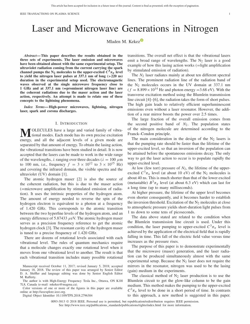
Fig. 1. Schematic of the experimental setup. 1—HV terminal connectedto the Marx generator, 2—copper ring, 3—copper plate, 4—metallic holderconnected to the generator, 5—step in the metallic flange, 6—metallicflange connected to the enclosure of the generator, 7 and 8—Plexiglasflanges, 9—partial reflector, 10—337-nm bandpass filter, 11—cylinder of 6-in(=15.24-cm) diameter, 12—graphite electrode of 2-in (=5.08-cm) diameter,13—copper mesh, 14—BNC connector, and 15—Tektronix CT-1 probe placedinto 2¾ inches nipple. B-dot probe was placed above the partial reflector, andthe photodiode was placed above 337-nm bandpass filter.
It involves the UV radiation to pump the N2 molecules to theupper-excited C3πu level for a long time. As the consequence,the new method yields the N2 laser pulses of long (>220 ns)duration. To demonstrate this idea, three sets of experimentshave been performed. In the first set of experiments, the clas-sical method was used to produce the N2 laser radiation at337.1 nm. In the second set of experiments, the electrical pulsefrom nine-stage Marx generator was applied to the structuregiven in Fig. 1. The microwave emissions close to 1 GHzhave been obtained. These microwave data are in accordancewith the data presented earlier [7]–[9]. In the third set ofexperiments, it was insured that the current carrying the sparkchannel under observation will conduct a large portion of thetotal current flowing in the setup. This makes that the sparkchannel will keep producing the UV radiation. In turn, the UVradiation will also keep pumping the upper-excited C3πu levelof the N2 molecules yielding the laser pulses at 337.1 nm oflong (>220 ns) duration.
II. DIAGNOSTICS
The diagnostic tools are: 10-GHz B-dot probe to measurethe radiation produced by the rail spark gap (Fig. 2) employedto obtain the Blumlein circuit and the microwave radiationexiting the cavity of the setup given in Fig. 1, TektronixCT-1 transformer/probe to measure the electrical current in thecavity, Hamamatsu R727 photodiode to record N2 emission,and 3-GHz Tektronix oscilloscope: Model: TDS 694C torecord the data.
B-dot probe made by Advanced Engineering ManufacturingSolutions, Albuquerque, NM 87123, USA, was calibrated inthe TEM cell. For a frequency of 1.08 GHz, the ampli-tude of the signal of 1 V corresponds to the electric fieldsof 3.07 kV/cm. The amplitude of the signal is linearly propor-tional to the frequencies in the range from 1 to 10 GHz.
Tektronix CT-1 probe measures the magnetic fields in thecavity in the RF and the microwave domain. The amplitudeof signal by the CT-1 probe depends on the orientation andon the position of the probe. The probe is observing only thelimited space in the cavity.
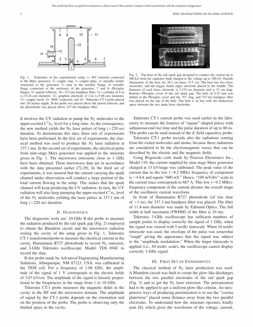
Fig. 2. Top base of the rail spark gap designed to conduct the current up to500 kA from the capacitor bank charged to the voltage up to 100 kV. Outsidedimensions of the base are 38.1 cm times 15.5 cm. The base has two brasselectrodes, and the trigger (knife edge) electrode placed in the middle. Thediameter of each brass electrode is 3.175-cm diameter and is 33 cm long.Bottom—Plexiglas cover of the rail spark gap. The hole of 6.25 mm wasdrilled in the Plexiglas cover and the “O” ring, and 337-nm bandpass filterwas placed on the top of the hole. The hole is in line with the midsectionspace between the two main brass electrodes.
Tektronix CT-1 current probe was used earlier in the labo-ratory to measure the features of “square”-shaped pulses withsubnanosecond rise time and the pulse duration of up to 80 ns.This probe can be used instead of the E-field capacitive probe.
Tektronix CT-1 probe records also the radiations comingfrom the exited molecules and atoms, because these radiationsare considered to be the electromagnetic waves that can bedescribed by the electric and the magnetic fields.
Using Rogowski coils made by Pearson Electronics Inc.,Model 110, the current supplied by nine-stage Marx generatorcharged at 15 kV/stage was calibrated. The peak value of thecurrent due to the low (∼9.2 MHz) frequency of componentis ∼4 kA and equals “600 mV.” Hence, “100 mV/div” scale inthe current trace corresponds to 667 A. This low (∼9.2 MHz)-frequency component of the current dictates the overall shapeof the oscillatory current waveform.
In front of Hamamatsu R727 photodiode (of rise timeof <1 ns), the 337.1-nm bandpass filter was placed. The filterof 11.8-mm diameter was made by Edmund Optics. The fullwidth at half maximum (FWHM) of the filter is 10 nm.
Tektronix 3-GHz oscilloscope has sufficient numbers ofsample points to display correctly the signal of 1 GHz, whenthe signal was viewed with 5 ns/div timescale. When 10 ns/divtimescale was used, the envelope of the pulse was somewhat“rough” giving the appearance that the signal was subjectto the “amplitude modulation.” When the larger timescale isapplied (i.e., 40 ns/div scale), the oscilloscope cannot displaycorrectly 1-GHz signal.
III. FIRST SET OF EXPERIMENTS
The classical method of N2 laser production was used.A Blumlein circuit was built to create the glow-like dischargesbetween the two parallel electrodes of the rail spark gap(Fig. 2) and to get the N2 laser emission. The preionizationhad to be applied to get a uniform glow-like column. An inex-pensive ways of producing preionization is to use the “coronaplate/wire” placed some distance away from the two parallelelectrodes. To understand how the structure operates, kindlynote [6], which gives the waveforms of the voltage, current,
This article has been accepted for inclusion in a future issue of this journal. Content is final as presented, with the exception of pagination.
KEKEZ: LASER AND MICROWAVE GENERATIONS IN NITROGEN 3
and the laser radiation emitted at 337.1 nm, and explain howthe circuit operates.
Review of the literature indicates the laser power at337.1 nm obtained varies from hundreds of kilowatts to over 1MW, the energy in the pulse greater than 5 mJ, and the averageenergy efficiency of 0.4%. This value of 0.4% was calculatedusing the data presented by 12 different studies that have beenstated in [4]. In these experiments, the Blumlein circuit wascharged in the range from 8 to 20 kV.
With the rail spark gap (Fig. 2) available in the laboratory,the uniform glow-type discharge was created between the twomain electrodes of the rail spark gap. A hole of 6.25 mmwas drilled on the narrow side of the Plexiglas enclosureand the “O” ring, and 337.1-nm bandpass filter was placedover the hole. The knife-edge electrode of the rail spark gapwas connected via 300-pF capacitor together with 100-M�resistor to the ground to provide the preionization. The knife-edge electrode was used as the “corona plate/wire.” Slightlybetter preionization was achieved by replacing the knife-edgeelectrode with a thin (0.18-mm diameter) wire. In general,it is necessary to optimize the distance between the “coronaplate/wire” and the main electrodes to obtain the maximumenergy/power of the laser pulse.
Each electrode of the rail spark gap was connected to astrip line of 35-cm length and a width w of 30 cm. Mylar wasused to provide the separation s (=0.4 mm) between the platesof the strip line. For the relative dielectric constant ε = 3,the impedance of the strip line is =377 � × s/(w · ×ε1/2) =0.29 �. The “hot” sides of these two strip lines were joinedwith the inductor of the large value to get the Blumlein circuitarrangement. This arrangement enables the voltage across themain electrodes to be equal to the voltage at which each singlestrip line was being charged.
The far end of the single strip line was connected to alow-impedance spark gap that was activated by 30-kV triggerpulse. This strip line was further shaped according to the ideaemployed in [5].
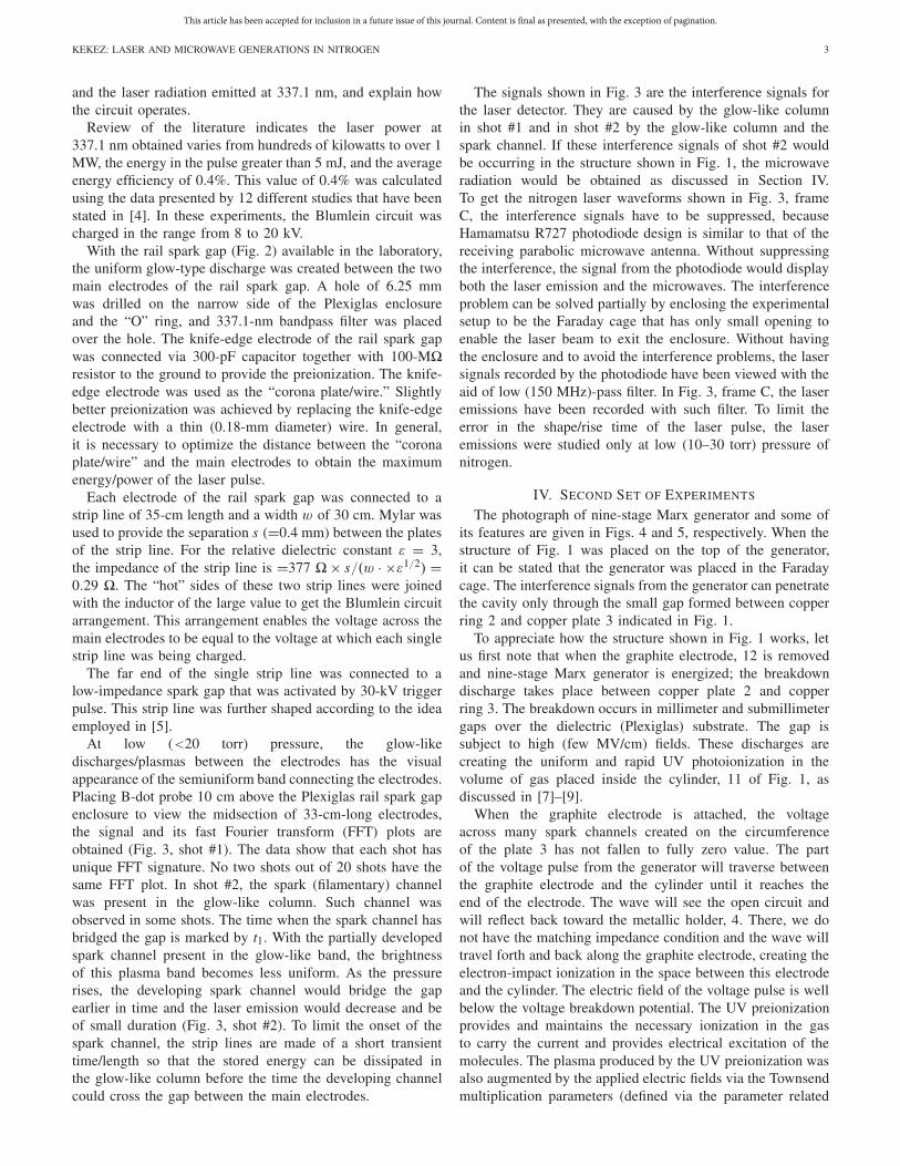
At low (<20 torr) pressure, the glow-likedischarges/plasmas between the electrodes has the visualappearance of the semiuniform band connecting the electrodes.Placing B-dot probe 10 cm above the Plexiglas rail spark gapenclosure to view the midsection of 33-cm-long electrodes,the signal and its fast Fourier transform (FFT) plots areobtained (Fig. 3, shot #1). The data show that each shot hasunique FFT signature. No two shots out of 20 shots have thesame FFT plot. In shot #2, the spark (filamentary) channelwas present in the glow-like column. Such channel wasobserved in some shots. The time when the spark channel hasbridged the gap is marked by t1. With the partially developedspark channel present in the glow-like band, the brightnessof this plasma band becomes less uniform. As the pressurerises, the developing spark channel would bridge the gapearlier in time and the laser emission would decrease and beof small duration (Fig. 3, shot #2). To limit the onset of thespark channel, the strip lines are made of a short transienttime/length so that the stored energy can be dissipated inthe glow-like column before the time the developing channelcould cross the gap between the main electrodes.
The signals shown in Fig. 3 are the interference signals forthe laser detector. They are caused by the glow-like columnin shot #1 and in shot #2 by the glow-like column and thespark channel. If these interference signals of shot #2 wouldbe occurring in the structure shown in Fig. 1, the microwaveradiation would be obtained as discussed in Section IV.To get the nitrogen laser waveforms shown in Fig. 3, frameC, the interference signals have to be suppressed, becauseHamamatsu R727 photodiode design is similar to that of thereceiving parabolic microwave antenna. Without suppressingthe interference, the signal from the photodiode would displayboth the laser emission and the microwaves. The interferenceproblem can be solved partially by enclosing the experimentalsetup to be the Faraday cage that has only small opening toenable the laser beam to exit the enclosure. Without havingthe enclosure and to avoid the interference problems, the lasersignals recorded by the photodiode have been viewed with theaid of low (150 MHz)-pass filter. In Fig. 3, frame C, the laseremissions have been recorded with such filter. To limit theerror in the shape/rise time of the laser pulse, the laseremissions were studied only at low (10–30 torr) pressure ofnitrogen.
IV. SECOND SET OF EXPERIMENTS
The photograph of nine-stage Marx generator and some ofits features are given in Figs. 4 and 5, respectively. When thestructure of Fig. 1 was placed on the top of the generator,it can be stated that the generator was placed in the Faradaycage. The interference signals from the generator can penetratethe cavity only through the small gap formed between copperring 2 and copper plate 3 indicated in Fig. 1.
To appreciate how the structure shown in Fig. 1 works, letus first note that when the graphite electrode, 12 is removedand nine-stage Marx generator is energized; the breakdowndischarge takes place between copper plate 2 and copperring 3. The breakdown occurs in millimeter and submillimetergaps over the dielectric (Plexiglas) substrate. The gap issubject to high (few MV/cm) fields. These discharges arecreating the uniform and rapid UV photoionization in thevolume of gas placed inside the cylinder, 11 of Fig. 1, asdiscussed in [7]–[9].
When the graphite electrode is attached, the voltageacross many spark channels created on the circumferenceof the plate 3 has not fallen to fully zero value. The partof the voltage pulse from the generator will traverse betweenthe graphite electrode and the cylinder until it reaches theend of the electrode. The wave will see the open circuit andwill reflect back toward the metallic holder, 4. There, we donot have the matching impedance condition and the wave willtravel forth and back along the graphite electrode, creating theelectron-impact ionization in the space between this electrodeand the cylinder. The electric field of the voltage pulse is wellbelow the voltage breakdown potential. The UV preionizationprovides and maintains the necessary ionization in the gasto carry the current and provides electrical excitation of themolecules. The plasma produced by the UV preionization wasalso augmented by the applied electric fields via the Townsendmultiplication parameters (defined via the parameter related
This article has been accepted for inclusion in a future issue of this journal. Content is final as presented, with the exception of pagination.
4 IEEE TRANSACTIONS ON PLASMA SCIENCE
Fig. 3. Two shots recorded at ∼20 torr pressure of nitrogen. In shot #1, the glow-like column was formed between the two main brass electrodes. In shot#2, the filamentary (spark) channel was also present in the glow-like column. Signals were recorded with 10-GHz B-dot probe. Their FFT plots are given inframe B. Numerous high-frequency signals indicated in frame B are superimposed on the oscillation of the signal with a frequency of 25 MHz. Hamamatsuphotodiode R727 together with 337-nm bandpass filter was used to record the laser emission. Blumlein circuit was charged to 12.5 kV. Separation betweenthe two brass electrodes was 8.7 mm.
to the ratio between the electric field and the neutral gasdensity) together with the parameters related to the high-speed(runaway) electron production.
The amplitude of the electric field on the graphite electrodedepends on the value of the charging voltage of the Marxgenerator, and on the spacing between copper plate 2 andcopper ring 3. To get the maximum value of the radiationexiting the cavity, it was learned that the Marx generator hasto be charged to the particular (optimum) value. If the chargingvoltage is a few kilovolts above the optimum value, the voltageacross the spark channels will fall causing the decrease of thecurrent flowing between the graphite electrode and the cylinderup to the factor of 2, resulting in the decrease of the ionizationand excitation of the constituencies in the gas by the electricfield. If the Marx generator is charged to slightly lower voltagein comparison to the optimum value, the trace of the radiationemission will have the steps at the beginning of the emission.
In zero-order approximation, the setup in Fig. 1 could beconsidered as RLC resonant circuit/cavity that can discrim-inate/reject the frequencies located away from the resonantfrequency on either side of the resonance. This feature isdescribed by the quality factor Q of the resonant cavity. TheB-dot probe records the radiation exiting the resonant cavity,and this is dictated by the quality factor Q [9]. As shownin [7], the microwave emission at the resonance can bedescribed in the term of the maser action, which means thatthe amplification of the microwave in the cavity behaves as ahigh-gain narrow bandwidth amplifier.
The resonant frequencies exiting the cavity can be con-sidered as coming from the coaxial waveguide. As shownin [7]–[9], the experimental evidence indicates that the TE11mode predominates. The TE11 (peak-on axis) has the smallestcutoff frequency value of all the TE modes propagatingin the coaxial waveguide. The cutoff wavelength for the
This article has been accepted for inclusion in a future issue of this journal. Content is final as presented, with the exception of pagination.
KEKEZ: LASER AND MICROWAVE GENERATIONS IN NITROGEN 5
Fig. 4. Interior of nine-stage Marx generator. In the final setup, Plexiglascylinder is placed between the interior and the metallic tube of 12-inches(30.48-cm) diameter that forms the enclosure of the generator. The specifi-cations of the nine-stage Marx generator are: six capacitors per module forthe total of 54 capacitors, 12 spark gaps per stage for the total of 120 sparkgaps, each spark gap can be adjusted to few micrometers, the capacitanceper stage is 15.6 nF, almost ideal coaxial structure achieved, impedance ofthe generator is circa 18 �, the charging voltage per stage varies from 10 to25 kV, at 25-kV/stage charge, the stored energy in the system is 44 J, andgood reproducibility.
Fig. 5. Output voltage across 300-� (18-inches (=45.72-cm) long) resistor.The top trace gives that the width of the double exponential pulse recorded tobe ∼420 ns. The bottom trace gives the rise time to be ∼2 ns. The generatorwas charged to 14.7 kV/stage.
TE11 mode is
λc = 1/4 × 1.873π(D + d) when D = 3d (1)
where D is the diameter of the inner wall of the cylinderand d is the diameter of the graphite electrode of the coaxialwaveguide. For D = 6 inches (=15.24 cm) and d = 2 inches(=5.08 cm) used in Fig. 1, (1) yields λc = 29.876 cm andfc = 1.004 GHz. The experimental data were found to be ofthe frequency range from 1.060 to 1.083 GHz [9].
Conducting the first set of the experiments and reading theliterature, it was learned that the laser emission can be obtainedonly if the density of the upper-excited C3πu level is abovecertain critical threshold. As shown in [4], this means that thecurvature of at least one electrode must be of small value, if theBlumein circuit was charged to relatively small (∼8 to 12 kV)voltage.
For this reason, to get the laser emission in the setup givenin Fig. 1, the knife-edge electrode of the rail spark gap wasinserted in the cavity. The cross section of the knife-edgeelectrode is triangle shaped with a base of 1.27 cm and a heightof 1.28 cm. This electrode is 33 cm long. The base of thiselectrode was attached to the inner wall of the cylinder 11. Oneend of the electrode was placed on step 5 shown in Fig. 1. Theelectrode was made to be in the parallel position with respectto the graphite electrode. The edge of this electrode was about3 mm away from the gap formed between the copper ring 2and the copper plate 3, shown in Fig. 1.
The effect of the knife-edge electrode on the microwavegeneration is presented in this section, and the effects of thiselectrode on the laser generation will be given in Section V.
When this electrode is absent, the cavity with the graphiteelectrode radiates (for example) in argon at 1.080 GHz(Fig. 8, [8]). With the knife-edge electrode present in thecavity, the main frequency exiting the cavity has fallen to1.052 GHz and the microwave pulse was subject to theamplitude modulation. This modulation varied from shot toshot. The FFT of the microwave signal shown in Fig. 6 givesthat this modulation is due to the main frequency lines ofthe cavity at 1.052 GHz, and the adjacent microwave line at1.295 GHz.
The current waveform measured with the TektronixCT-1 probe (Fig. 6) gives the growth and decay of the currentcomponent at 1.294 GHz. This component is superimposed onthe trace of the current at a frequency of 259 MHz as well onthe trace of the low (∼9.2 MHz)-frequency component. The259-MHz frequency corresponds to the double transit time forthe voltage to traver forth and back along the graphite elec-trode. The low (∼9.2 MHz) frequency not noted in Fig. 6 givesthe appearance of the oscillatory current waveform.
In Fig. 6, the quality factor Q of the resonant cavityamplifies the low amplitude signal at 1.062 GHz shown inthe FFT of the current trace to reach the peak at 1.052 GHzpresented in the FFT plot of the signal. The quality factor alsosuppresses the large amplitude of a frequency of 1.294 GHzshown in the current trace to become the amplitude of smallervalue at 1.295 GHz in the FFT plot of the signal.
In general, the interaction between two signals of thesame amplitude and of different frequencies f1 and f2 ispresented [10]
�F × �t = 1 where �F = � f1 − f2� (2)
where �t is the time interval at which the resulting signal haszero value between the two consecutive interactions. �t keepsrepeating in time as long as the signals f1 and f2 are applied.In the literature, (2) is referred to describe the coherence effect.Equation (2) can also be applied if the amplitudes of thesignal: f1 and f2 are not of the same value, and their temporalbehavior is different in terms of the decay of amplitudein time.
Using the data presented in Fig. 6, Table I is derived andshows that the experimental difference from the theoreticalvalue is less than 2%.
To learn more about the interaction between these twofrequencies, Fig. 7 is obtained. The signal exiting the cavity
This article has been accepted for inclusion in a future issue of this journal. Content is final as presented, with the exception of pagination.
6 IEEE TRANSACTIONS ON PLASMA SCIENCE
Fig. 6. Experimental data of microwave emission recorded in nitrogen at 150-torr pressure. Signal in frame A was recorded with B-dot probe. Current inframe A was obtained using Tektronix CT—1 current probe. Frames B are the FFT plots of the signal and of the current, respectively. � f1 is the FWHMof the line at 1.052 GHz. �F is the frequency difference between 1.295 and 1.052 GHz. Knife-edge electrode was present in the cavity. Nine-stage-Marxgenerator was charged at 12.5 kV/stage.
TABLE I
DATA OF FIG. 6 ARE COMPARED WITH THEORY: �F × �t = 1
was viewed by the B-dot probe with the aid of a low (1 GHz)-pass filter. This filter attenuates to some degree the 1.052-GHzsignal, but it has suppressed fully the signal at 1.295 GHz.In Fig. 7, shot #1 corresponds to the case, as if the knife-edge electrode would be absent in the resonant cavity. In shot#3, the current waveform has the largest value of the currentcomponent at 1.294 GHz that was ever recorded.
V. THIRD SET OF EXPERIMENTS
The knife-edge electrode was introduced in the cavity withthe hope of increasing the density of the upper-excited C3πu
level above certain critical threshold to achieve the laser
emission. When the 337.1-nm filter and the photodiode werepositioned to view the gap between copper plate 2 and copperring 3, it was observed from time to time that a smalldetectable amplitude of the laser emission of circa 12-nsduration was followed by a pause in the emission and lowamplitude emissions were recorded to last over 200 ns. In theseinitial experiments, the nitrogen pressure was 60 torr.
To make sure of having the corona/streamer filament glidingthe dielectric (Plexiglas) substrate to be always in line wherethe filter was located, the experimental setup was modified.The diameter of the copper plate was decreased by 1 cm. Thetungsten rod of 1-mm diameter was attached to the metallicholder 4 (Fig. 1). The tungsten rod was positioned to be 2 mmabove the copper plate. The gap between the tip of the rod andthe copper ring 3 was adjusted to about 1.5 mm.
Under such arrangement, as expected, there would be dis-tribution of the current during the electrical breakdown. Someportion of the current will be conducted by the corona/streamerfilament gliding over the dielectric substrate around the cir-cumference of the copper plate. The remaining part of thecurrent will be conducted by the spark breakdown between
This article has been accepted for inclusion in a future issue of this journal. Content is final as presented, with the exception of pagination.
KEKEZ: LASER AND MICROWAVE GENERATIONS IN NITROGEN 7
Fig. 7. Three shots of microwave emission at 150-torr pressure are shown in the left, and the corresponding current traces in the right. A frequencyof 1.294 GHz presents in the current waveform shown in the right has small amplitude in shot #1 and the very large amplitude in shot #3. Signal and thecurrent were recorded, as in Fig. 6. Knife-edge electrode was present in the cavity. Nine-stage Marx generator was charged to 12.5 kV/stage.
the tip of the rod and the copper ring. By applying higherpressure of nitrogen in the chamber, it was possible to controlthe amount of the current conducted by the corona/streamerfilaments and to ensure that the spark channel would conducta larger portion of the current.
In Fig. 8, the laser emission at 337.1-nm wavelengthwas obtained when the nitrogen pressure in the chamberwas 150 torr. Fig. 8 also shows that the reproducibility ofthe laser emission from shot to shot was satisfactory.
Fig. 9 is obtained by changing the nitrogen pressure inthe cavity. The data obtained provide some indication how
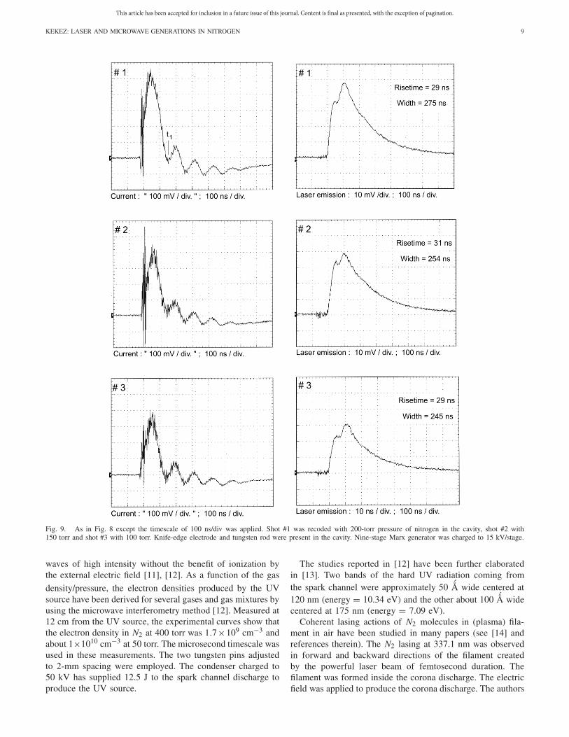
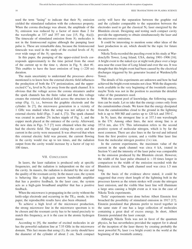
the laser emission varies versus the current. At the firstglance, this dependence appears to be the linear relationship.After the emission reaches the peak value, the exponentialdecay of the emission was observed in most of the shotsrecorded. When the pressure in the cavity rises above 250 torr,the decay of the emission was no longer a smooth exponentialcurve, but rather a modulated curve that follows the oscilla-tions of the current after time t1. In Fig. 9, shot #1, t1 isindicated.
The frequency of the modulation in the decaying portionof the emission is almost of the same value as the frequency
This article has been accepted for inclusion in a future issue of this journal. Content is final as presented, with the exception of pagination.
8 IEEE TRANSACTIONS ON PLASMA SCIENCE
Fig. 8. Three shots of laser emission recorded with the photodiode are shown in the right, and the corresponding current traces in the left. A 150 torr ofnitrogen was introduced in the cavity. Knife-edge electrode and tungsten rod were present in the cavity. Current was measured, as in Fig. 6. Nine-stage Marxgenerator was charged to 15 kV/stage.
in the current waveform; however, the emission has also astrong second harmonics.
When atmospheric air has replaced the nitrogen at 400 torrin the cavity, the emission in air has very similar fea-tures. The amplitude and the shape of the pulse remainalmost the same. This is a rather surprising and unexpectedresult.
Please note that the industrial grade nitrogen was used inthe experiments, and throughout the measurements of the laserpulse, special care was taken to inhibit the stray light reaching
the photodiode. The radiation at 337 nm was recorded only inall the data presented.
VI. DISCUSSION
To understand the data obtained, it is necessary to learnmore about the pumping of N2 molecules to the upper-excited C3πu level by the UV radiation and the process ofthe photoionization.
Photoionization from excited states is the mechanism of gasbreakdown by the visible and UV spectrum electromagnetic
This article has been accepted for inclusion in a future issue of this journal. Content is final as presented, with the exception of pagination.
KEKEZ: LASER AND MICROWAVE GENERATIONS IN NITROGEN 9
Fig. 9. As in Fig. 8 except the timescale of 100 ns/div was applied. Shot #1 was recoded with 200-torr pressure of nitrogen in the cavity, shot #2 with150 torr and shot #3 with 100 torr. Knife-edge electrode and tungsten rod were present in the cavity. Nine-stage Marx generator was charged to 15 kV/stage.
waves of high intensity without the benefit of ionization bythe external electric field [11], [12]. As a function of the gas
density/pressure, the electron densities produced by the UVsource have been derived for several gases and gas mixtures byusing the microwave interferometry method [12]. Measured at12 cm from the UV source, the experimental curves show thatthe electron density in N2 at 400 torr was 1.7×109 cm−3 andabout 1×1010 cm−3 at 50 torr. The microsecond timescale wasused in these measurements. The two tungsten pins adjustedto 2-mm spacing were employed. The condenser charged to50 kV has supplied 12.5 J to the spark channel discharge toproduce the UV source.
The studies reported in [12] have been further elaboratedin [13]. Two bands of the hard UV radiation coming fromthe spark channel were approximately 50 Å wide centered at120 nm (energy = 10.34 eV) and the other about 100 Å widecentered at 175 nm (energy = 7.09 eV).
Coherent lasing actions of N2 molecules in (plasma) fila-ment in air have been studied in many papers (see [14] andreferences therein). The N2 lasing at 337.1 nm was observedin forward and backward directions of the filament createdby the powerful laser beam of femtosecond duration. Thefilament was formed inside the corona discharge. The electricfield was applied to produce the corona discharge. The authors
This article has been accepted for inclusion in a future issue of this journal. Content is final as presented, with the exception of pagination.
10 IEEE TRANSACTIONS ON PLASMA SCIENCE
used the term “lasing” to indicate that their N2 emissionyielded the stimulated radiation with the coherence property.When the corona discharge was absent, the amplitude of theN2 emission was reduced by a factor of more than 2 forthe wavelengths at 337 and 357 nm (see [15, Fig. 4(a)]).The timescale of stimulated emission from N2 molecules isnot in the femtosecond regime although the pumping laserpulse is. These are remarkable data, because the femtosecondtimescale was used in the study of the excited levels of N2over wide range of the N2 spectrum.
In this paper, the pumping of the upper-exited levels cor-responds approximately to the time period from the onsetof the current up to the time t1 shown in Fig. 9, shot #1.This enables to have the laser emission of long (>220 ns)duration.
The main uncertainty to understand the processes above-mentioned is to know how the external electric field influencesthe production of both the UV preionization, and the upper-excited C3πu level in N2 far away from the spark channel. It isobvious that the voltage across the corona streamers and/orthe spark channels has the finite value and that this voltagecreates the external electrical field across the structure in thesetup (Fig. 1), i.e., between the graphite electrode and thecylinder. In [7], the microwave generation in a vicinity of1 GHz was studied when the setup was not subject to theexternal electric field (Figs. 3 and 4, [7]). The spark channelwas created in another 2¾ inches nipple of Fig. 1, and thecopper mesh placed at the entrance of the cavity. Afterward,the new data in Figs. 5–7 [7] were obtained when the setuphad the electric field. The signal exiting the cavity and thecurrent in the cavity were measured. It was observed that whenthis external electric field was present, the current flowingin the cavity would rise up to ten times, and the radiationoutput from the cavity would increase by a factor of (up to)100 times.
VII. CONCLUSION
In lasers, the laser radiation is produced only at specificfrequencies, and the radiation is independent on the size ofthe cavity. In masers, the radiation is dictated by the size andthe quality of the resonant cavity. In the maser case, the systemis behaving like a high-gain narrow bandwidth amplifierthat has a positive feedback. In the laser case, the systemacts as a high-gain broadband amplifier that has a positivefeedback.
When the microwave is propagating in the cavity without theknife-edge electrode and occurring in the TE11 mode, in thispaper, the reproducible results have also been obtained.
To achieve a high level of the microwave production,the strong microwave line in the microwave spectrum is tobe chosen and the resonant cavity has to be tuned precisely tomatch this frequency, as it is the case in the atomic hydrogenmaser.
According to [9], the number of excited molecules in airhas the powerful radiation line at 7.55 GHz in the microwavedomain. This fact means that using (1), the cavity should havethe diameter of the cylinder of about 2 cm. Such compact
cavity will have the separation between the graphite rodand the cylinder comparable to the separation between theelectrodes used to get the classical N2 laser energized by theBlumlein circuit. Designing and testing such compact cavityprovide the opportunity to obtain simultaneously the laser andthe microwave emissions.
It could be interesting to mention some other ideas of thelaser production in air, which should be the topic for futureresearch.
Nikola Tesla recorded the puzzling event in his study at War-denclyffe Tower, Long Island, USA, during 1901–1906 [16].A bright event to the naked eye at night took place over a largearea near the coast line of Long Island and over the sea. It wasthought that this bright event had been caused by the electricaldischarges triggered by his generator located at WardenclyffeTower.
The details of his experiments are unknown and how he hadachieved the bright event remains not clear. With the diagnostictools available in the very beginning of the twentieth century,maybe Tesla was not in the position to ascertain the detailedvalue of the parameters used.
With the current pool of knowledge, the following sugges-tion can be made. Let us take that the energy comes only fromthe cumulonimbus clouds. We know that the energy dissipatedfrom the cumulonimbus cloud to the ground in the lightningbolt is up to 500 MJ and carries up to 120 kA and 350 C.
In N2 laser, the strongest line is at 337.1-nm wavelengthin the UV. Among other lines, the next strong line is at357.6 nm, also UV. This information refers to the secondpositive system of molecular nitrogen, which is by far themost common. There are also lines in the far-red and infraredfrom the first positive system, and a visible blue laser linefrom the molecular nitrogen positive (1+) ion.
In the current experiments, the maximum value of thecurrent in the spark channel was circa 4 kA, (stated inSection V) and the intensity of the laser pulse was comparableto the emission produced by the Blumlein circuit. However,the width of the laser pulse obtained is >10 times longer incomparison to the width of the emission recorded with theBlumlein circuit. The spark channel used was circa 1.5 mmlong.
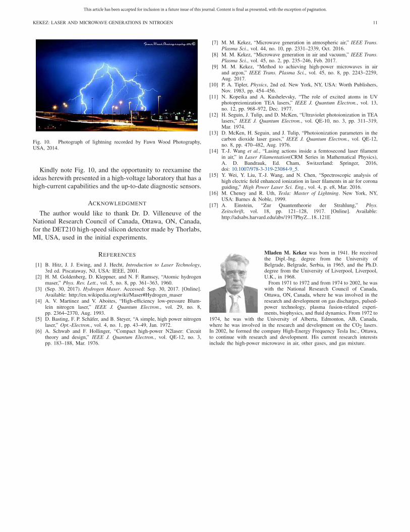
On the basis of the evidence above stated, it could besuggested that every short length of the lightning bolt in theprocesses known as the return strokes will create the nitrogenlaser emission, and the visible blue laser line will illuminatea large area causing a bright event as it was in the case ofNikola Tesla experiments.
Tesla’ experiments were done before Albert Einstein firstbroached the possibility of stimulated emission in 1917 [17].Einstein postulated that photons prefer to travel together inthe same state if one has a large collection of moleculescontaining a great deal of excess energy. In short, AlbertEinstein postulated the laser concept.
Although Nikola Tesla was not in favor of the quantumphysics, he has nevertheless provided the support for it aheadof the inception of the laser theory by creating probably themost powerful N2 laser (=a bright event) in the world at thebeginning of the twentieth century.
This article has been accepted for inclusion in a future issue of this journal. Content is final as presented, with the exception of pagination.
KEKEZ: LASER AND MICROWAVE GENERATIONS IN NITROGEN 11
Fig. 10. Photograph of lightning recorded by Fawn Wood Photography,USA, 2014.
Kindly note Fig. 10, and the opportunity to reexamine theideas herewith presented in a high-voltage laboratory that has ahigh-current capabilities and the up-to-date diagnostic sensors.
ACKNOWLEDGMENT
The author would like to thank Dr. D. Villeneuve of theNational Research Council of Canada, Ottawa, ON, Canada,for the DET210 high-speed silicon detector made by Thorlabs,MI, USA, used in the initial experiments.
REFERENCES
[1] B. Hitz, J. J. Ewing, and J. Hecht, Introduction to Laser Technology,3rd ed. Piscataway, NJ, USA: IEEE, 2001.
[2] H. M. Goldenberg, D. Kleppner, and N. F. Ramsey, “Atomic hydrogenmaser,” Phys. Rev. Lett., vol. 5, no. 8, pp. 361–363, 1960.
[3] (Sep. 30, 2017). Hydrogen Maser. Accessed: Sep. 30, 2017. [Online].Available: http://en.wikipedia.org/wiki/Maser#Hydrogen_maser
[4] A. V. Martinez and V. Aboites, “High-efficiency low-pressure Blum-lein nitrogen laser,” IEEE J. Quantum Electron., vol. 29, no. 8,pp. 2364–2370, Aug. 1993.
[5] D. Basting, F. P. Schäfer, and B. Steyer, “A simple, high power nitrogenlaser,” Opt.-Electron., vol. 4, no. 1, pp. 43–49, Jan. 1972.
[6] A. Schwab and F. Hollinger, “Compact high-power N2laser: Circuittheory and design,” IEEE J. Quantum Electron., vol. QE-12, no. 3,pp. 183–188, Mar. 1976.
[7] M. M. Kekez, “Microwave generation in atmospheric air,” IEEE Trans.Plasma Sci., vol. 44, no. 10, pp. 2331–2339, Oct. 2016.
[8] M. M. Kekez, “Microwave generation in air and vacuum,” IEEE Trans.Plasma Sci., vol. 45, no. 2, pp. 235–246, Feb. 2017.
[9] M. M. Kekez, “Method to achieving high-power microwaves in airand argon,” IEEE Trans. Plasma Sci., vol. 45, no. 8, pp. 2243–2259,Aug. 2017.
[10] P. A. Tipler, Physics, 2nd ed. New York, NY, USA: Worth Publishers,Nov. 1983, pp. 454–456.
[11] N. Kopeika and A. Kushelevsky, “The role of excited atoms in UVphotopreionization TEA lasers,” IEEE J. Quantum Electron., vol. 13,no. 12, pp. 968–972, Dec. 1977.
[12] H. Seguin, J. Tulip, and D. McKen, “Ultraviolet photoionization in TEAlasers,” IEEE J. Quantum Electron., vol. QE-10, no. 3, pp. 311–319,Mar. 1974.
[13] D. McKen, H. Seguin, and J. Tulip, “Photoionization parameters in thecarbon dioxide laser gases,” IEEE J. Quantum Electron., vol. QE-12,no. 8, pp. 470–482, Aug. 1976.
[14] T.-J. Wang et al., “Lasing actions inside a femtosecond laser filamentin air,” in Laser Filamentation(CRM Series in Mathematical Physics),A. D. Bandrauk, Ed. Cham, Switzerland: Springer, 2016,doi: 10.1007/978-3-319-23084-9_5.
[15] Y. Wei, Y. Liu, T.-J. Wang, and N. Chen, “Spectroscopic analysis ofhigh electric field enhanced ionization in laser filaments in air for coronaguiding,” High Power Laser Sci. Eng., vol. 4, p. e8, Mar. 2016.
[16] M. Cheney and R. Uth, Tesla: Master of Lightning. New York, NY,USA: Barnes & Noble, 1999.
[17] A. Einstein, “Zur Quantentheorie der Strahlung,” Phys.Zeitschrift, vol. 18, pp. 121–128, 1917. [Online]. Available:http://adsabs.harvard.edu/abs/1917PhyZ...18..121E
Mladen M. Kekez was born in 1941. He receivedthe Dipl.-Ing. degree from the University ofBelgrade, Belgrade, Serbia, in 1965, and the Ph.D.degree from the University of Liverpool, Liverpool,U.K., in 1968.
From 1971 to 1972 and from 1974 to 2002, he waswith the National Research Council of Canada,Ottawa, ON, Canada, where he was involved in theresearch and development on gas discharges, pulsed-power technology, plasma fusion-related experi-ments, biophysics, and fluid dynamics. From 1972 to
1974, he was with the University of Alberta, Edmonton, AB, Canada,where he was involved in the research and development on the CO2 lasers.In 2002, he formed the company High-Energy Frequency Tesla Inc., Ottawa,to continue with research and development. His current research interestsinclude the high-power microwave in air, other gases, and gas mixture.