ieee transactions on plasma science. vol. 33. no ... · ieee transactions on plasma science. vol....
TRANSCRIPT
IEEE TRANSACTIONS ON PLASMA SCIENCE. VOL. 33. NO. 1. FE I:IR UA RY 2005
Pseudoresonant Laser Wakefield Acceleration Driven by lO.6-~Ll11 Laser Light
W. D. Kimura, Sellior Member, IEEE, N. E. Andreev, M. Babzien, L Ben-Zvi , D. B. Cline, C. E. Dilley, S. C. Gottschalk , S. M. Hooker, K. P. Kusche, S. Y. Kuznelsov, L Y. Pavlishin, L Y. Pogorelsky, A. A. Pogosova,
L. C. Steinhauer, A. Ting, Y. Yakimenko, A. Zigler, and F. Zhou
Ab~"rac'-This paper describes an eXllerinwnt to demonstrate, for the first time, laser wakefie ld acceleration (LWf'A), driven by 1O.6-IJm light from a CO:,} laser. This experiment is also noteworthy beca use it will operate in a pseudoresonant LWFA reg ime, in which the laser-pulse-length is too long for r esonant LWFA, but too short for self-modulated LWFA. Nonetheless, high acceleration gradients lire s till possible. This experiment builds upon an earlier experiment called staged electron laser acceleration (STELLA), where efficient trapping and monoenergetic laser acceleration of e lectrons were d emonstrated using inverse free e lectron lasers. The aim is to apply the STELLA approach of laser·driven microbunch fo r mation followed by laser-drh'en trapping and acceleration to LWFA. These capabili ties arc important {'Ol' 11 pr:lctical electron linear accelerator based upon LWFA.
Illdex 7emu-Capillary discharge, carhon dioxide lasers , electron a ccele rators, laser accelerators, laser wakefield acceleration.
I. INTRODUCTION
A NUMB ER of different mechanisms are being investigated arollnd the world to develop electron linear accelerators
driven either directl y or indirectly by laser light: see examples in [ I J. Hi gh acceleration gradients> 1 GeV 1m have been demonstrated: thus, laser-driven accelerators (laser Jinaes) may someday enable compact. potentially less expens ive accelerators.
However. acceleration of useful amounts of charge requires efficiently grouping the electrons into a microbunch(cs). and trapping the microbunch(es) in the ponderomotive potent ial wel l CbuckeC) of the accelerating wave. This can bc an electromagnctic wave. such as in inverse free electron lasers (IFELs)
Manuscript re"ei'ed Juty 16. 2004: r<)vised Sepkmocr S. 2004. This work w,l> supported by thc U,S. Departmcnt of Encrgy undcr Grants DE-FG02-04ER4t294, DE-AC02-98CHI0886. and DE-FG03-92ER40695.
W. D. Kimtlra, C. E. Diliey. and S, C. G011S~h,!lk are wilh STI Optroni(:s. Inc .. IkllevlIc. WA 98004-1495 USA (e-mail: wkimura@~liOPlrOnics. com )
N. E. Andreev. S. V KUl.TleISOv. and A. A. Pogosova arc wilh thc tnslillilC for High Energy Densil ie,. Russian Acadcmy of Scicnccs. Moscow t254 12. Russin
1\ \. Bab/ien. I Ben-Zvi. K. P Kuschc. t. V. Pavlishin, I. V. Pogorcisky. and V Yakimenko arc wilh Ihc Brookhavcn National Laboratory. Upton. NY 11973 USA
D. B. Clinc and F. Zhou arc wilh Ihc Uni\'Crsi tyofCllifornia at Los Angeles. Los Angclcs. CA 9(()95 USA
S. M, I looker is wilh the Universi ty of Ox for <i. Oxford OX ! 3PU. U.K. L. C. Sleinn,lLJer i, wilh Ihe Redmond Plasma Physics Laboralory. Univcrsi ty
ofW,,~hington . Redmond. WA 9S052 USA. A. Ting is with thc Naval Rcscarch Laboratory. Washington. DC 20375 USA A. Ziglcr is wilh the Racah Inst itule of Physi<:s. The Hebrew Univer:sily.
Jcnlsalem 9 l9().t, Israel. Digital Obj~'<;t Identifier 10 !l09rrrS.2004.841173
[2], or a plasma wave, such as in laser wakefield acceleration (LW FA) [3 [. Having a narrow energy spread of the accelerated electrons (i .e., monoenergetic) is also important for efficient trapping and is often required by many applica:ions.
Generally. these mechanisms have practical limits to the max imum length of the acceleration regions. For example, gradual phase slippage can occur between the accelerating wave and the accelerated electrons. Hence, it will be nccessary to repeat the acceleration process by staging multiple laser-:1riven acceleration sections. This implies the need to resynchronize the phase of the trapped electrons wi th the accelerating wave in these stages.
This process of trapping and staging is exactly analogous to the method ut il ized in microwave-driven accelerators. A key difference is the wavelength of the accelerating wave in laserdriven devices may be of order one to several hundred microns instead of centimeters.
Most laser acceleration research has focused on studying specific acceleration processes. The staged electron laser acceleration (STELLA) experiment r4] was specifically designed 10 demonstrate efficient trapping and staging of laser-driven acceleration devices. STELLA used IFELs. which were chosen primarily for experimental convenience. In fact, the overall STELLA approach can be applied to other acceleration methods.
This approach consists of first creating a microbunch or train of microbunches using the laser-driven mecharism. e.g. , IFEL. The microbunches arc spaced apart by a Ienglh \",cel. where Anccd is either the laser or plasma wavelength. The microbunch length is also very short , typically'" Anccd/lO. which means the microbunch(es) are in a configuration that allows them to be trapped and acceleratcd in subsequent laser-driven stages .
This paper describes an experiment to apply th~ STELLA approach to a plasma-based acceleration scheme. specifically LWFA. The experiment is called STELLA-laser wakefield (STELLA-LW). This experiment is motivated by the faci that IFELs have inherent scaling limitations and. in particular, become inefficient as the energy of the c-beam increases. [n contrast. LWFA has more favorable scaling ch~racteristics and offers the possibility of much highcr accelcration gradients than IFELs.
The next section describes the STELLA-LW experiment and predicted results. Conclusions are given in Section [[I , as well as implications of thi s ex perimenl and possible future work .
()J93-3ll t3/$20,00 © 2005 IEEE
Report Documentation Page Form ApprovedOMB No. 0704-0188
Public reporting burden for the collection of information is estimated to average 1 hour per response, including the time for reviewing instructions, searching existing data sources, gathering andmaintaining the data needed, and completing and reviewing the collection of information. Send comments regarding this burden estimate or any other aspect of this collection of information,including suggestions for reducing this burden, to Washington Headquarters Services, Directorate for Information Operations and Reports, 1215 Jefferson Davis Highway, Suite 1204, ArlingtonVA 22202-4302. Respondents should be aware that notwithstanding any other provision of law, no person shall be subject to a penalty for failing to comply with a collection of information if itdoes not display a currently valid OMB control number.
1. REPORT DATE SEP 2004 2. REPORT TYPE
3. DATES COVERED 00-00-2004 to 00-00-2004
4. TITLE AND SUBTITLE Pseudoresonant Laser Wakefield Acceleration Driven by lO.6-um Laser Light
5a. CONTRACT NUMBER
5b. GRANT NUMBER
5c. PROGRAM ELEMENT NUMBER
6. AUTHOR(S) 5d. PROJECT NUMBER
5e. TASK NUMBER
5f. WORK UNIT NUMBER
7. PERFORMING ORGANIZATION NAME(S) AND ADDRESS(ES) Naval Research Laboratory,Washington,DC,20375
8. PERFORMING ORGANIZATIONREPORT NUMBER
9. SPONSORING/MONITORING AGENCY NAME(S) AND ADDRESS(ES) 10. SPONSOR/MONITOR’S ACRONYM(S)
11. SPONSOR/MONITOR’S REPORT NUMBER(S)
12. DISTRIBUTION/AVAILABILITY STATEMENT Approved for public release; distribution unlimited
13. SUPPLEMENTARY NOTES
14. ABSTRACT This paper describes an eXllerinwnt to demonstrate for the first time, laser wakefield acceleration(LWf’A), driven by 1O.6-IJm light from a CO:,} laser. This experiment is also noteworthy beca use it willoperate in a pseudoresonant LWFA regime in which the la ser-pulse-length is too long for r esonantLWFA, but too short for self-modulated LWFA. Nonetheless, high acceleration gradients lire s till possible.This experiment builds upon an earlier experiment called staged electron laser acceleration (STELLA)where effi cient trapping and monoenergetic laser acceleration of electrons were d emonstrated usinginverse free e lectron lasers. The aim is to apply the STELLA approach of laser?driven microbunch fo rmation followed by laser-drh’en trapping and acceleration to LWFA. These capabilities arc important{’Ol’ 11 pr:lctical electron linear accelerator based upon LWFA.
15. SUBJECT TERMS
16. SECURITY CLASSIFICATION OF: 17. LIMITATION OF ABSTRACT Same as
Report (SAR)
18. NUMBEROF PAGES
5
19a. NAME OFRESPONSIBLE PERSON
a. REPORT unclassified
b. ABSTRACT unclassified
c. THIS PAGE unclassified
Standard Form 298 (Rev. 8-98) Prescribed by ANSI Std Z39-18
""'""" TubeWalis
Wakelield
·scha 'ge Plasma
II Witness electron
~)
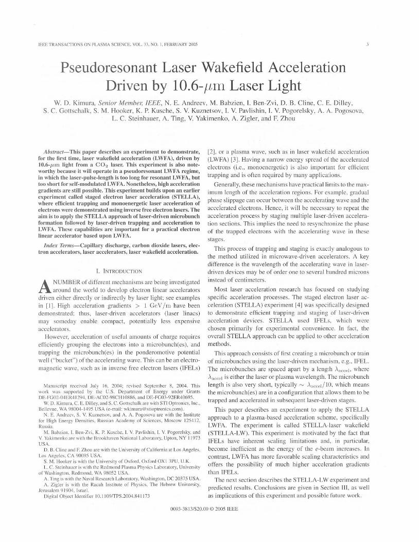
Fig. I. Basic scheme fOf resonam laser wal::efield acceleration (LWI'i\) (a) Prepare :.ppropri<lle pli,sllll! wilh p;lrabolic densi ty distribut ion for ch~nneling laser light. (b) Send laser pulse Ihrough pl;.&"':I. which crc;11CS
wal::elield bchirKI laser pulse. Properly phased witnc5s electron can then be accelerated by tile wakefield.
II. D ESCRIPTION OF STELLA-LW EXPERIMENT
A. Pselldoresonanr LltlfA
In a typical LWFA experimental arrangement. the e-beam and laser beam interact within a plasma as illustrated in Fig. I. This plasma mi ght be formed using a g:ls jet [5], a laser beam focused by an axicon in a gas l6J, or a capillary discharge [7J. If the plasma density distribution has the proper characterh;tics [sec Fig. I (a)], it can also channel the laser beam L8]. Without this channeling effect, a tightly foc used laser beam could nOI be maintained longer than a Rayleigh le ngth.
The laser beam excites a wakefield in the phlsma. wh ich can be made to travel close 10 the speed of light c. This wakefield consists of a plasma wave with alternating concentrations of negative and positive charge: see Fig. l(b). The e-beam electrons sense these charges. Depending on the electron's phase position in this wakefi eld. it can be accelerated or decelerated. Thus, the wakefield has many of the same basic characteri stics as the laser field in an IFEL. If electrons arc di stributed over all phases of the wakefield, the n their energy will be modulated just as in an IFEL buncher. If the elcctrons arc concentrated in a microbunch whose longitudinal and transverse size is small e nough. these electrons can be trapped and accelerated by the wakefield. Key differences are the wakefield is capable of much higher acce leration gradients than IFELs and there can be strong radial focusing forces on Ihe e-be:l1l1.
There arc two well-known modes of LWFA operati on. The first is resonant LWFA. where the laser pulse length TJ:. ,..... ).,1>/2(', where ).,1' is the plasma wavelength . TIle short laser pulse resonantly excites a wakefield in the plasma because its primary Fourier component matches the plasma frequency. The plasma wavelength is related to the plasma density n~ via
(3.3 x lOW) Ap (/t.ltl ) '" . Jnr (CIll 3)
(1 )
The second mode of operation is self-modulated LWFA (SMLWFA). in which the laser pulse length is intentionally much longer than Ap /2c. Thi s permi ts the laser electric field to feed energy inlo a wakefield via forward Raman scattering (FRS)
IF.F.F. TRANSACTIONS ON PI.ASMA SCIENCE. VOL. 33. NO.1. FEBIWARY 20M
andlor self-modulation instabilit y. Much higher gradients are possible usi ng SM -LWFA. However. it starts from noise and becomes a highly nonlinear process. which may interfere with control of the wakefield phase.
LWFA experiments to date have primaril y conccntrated on studying the basic mechanism and have typically been perfomled using O.8- 1-/tllllaser wavelengths. where terawau- lcvcl (TW-Ievel) lasers arc readily available. The STELLA- LW experiment will be one of tile first to investigate LWFA usi ng IO.6-ILUl laser wave length. This is made possible by recent upgrades to the Brookhavcn National Laboratory Accelerator Test Faci lity (ATF) CO2 laser. which is presentl y able to produce ncar-terawall peak powcr levels with IO-ps pulse length. Evelllu:rlly. the ATF CO2 laser should produce pulses as short as~2ps.
Wakefield generat ion at long laser wavelengths has certain inherent advantages 19]. One is that the normalized laser field parameter (£ is proportional 10 the laser wavelength AL (i .e .. a == e,EL /wuu:, where e is the electron charge, EL is the laser electric field, w is the laser frequency, and 111 is the electron mass). This means for the same laser beam focus area. 1O-IWl light will provide a factor of 10 increase in (I, compared to l-I{m laser light, and a 100 times increase in the ponderornotive potential. which scales as a2 . While it is true that I-lUll light can be focused to a small er area than 1O-11ll1 light to compen~ate
for thi s effect, the minimum ugable lascr beam size is limited by the minimum e-beam size that can be obtained . The e-beam size de]X!nds on other factors. such as the e-beam emittance and space charge spreading. From an experimental viewpoint. larger e-beam sizcs arc gencrally favored because thcse limita· lions are eased. Hence. LWFA at IO.6/~!Il has certain practical advantages.
Theoretical analysis of LWI-i\ driven by 1O.6-/UIi 13scr light has already been performed 1101- 1121. For the anticipated conditions of the ATF TW C02 laser (i.e. , "-' 2 ps pulse length. 5 J/pulsc), an electric field gradient of "-' I CV /m i ~ predicted. This is for n ". '" 1016 cm - J • which is higher than the usual den sity required to satisfy the resonant condition for a 2-ps laser pu lse. Even more noteworthy is this high gradient arises from a strong wakeficld that is created despite the fact the 2-ps laser pulse is too long for resonant LWFA and too short for SM-LWFA. Ii was found that interaction of the lascr light with the plasma causes pulsc stcepcning to occur at the trailing edge of the light pul se. This effectively initiates the wakefield generation as if the laser pulse length were much shorter. but the pul se terminates before FRS can playa significant role. Nevertheless, the wakefields produced can be comparable to those formed by SM-LWFA with a longer pulse.
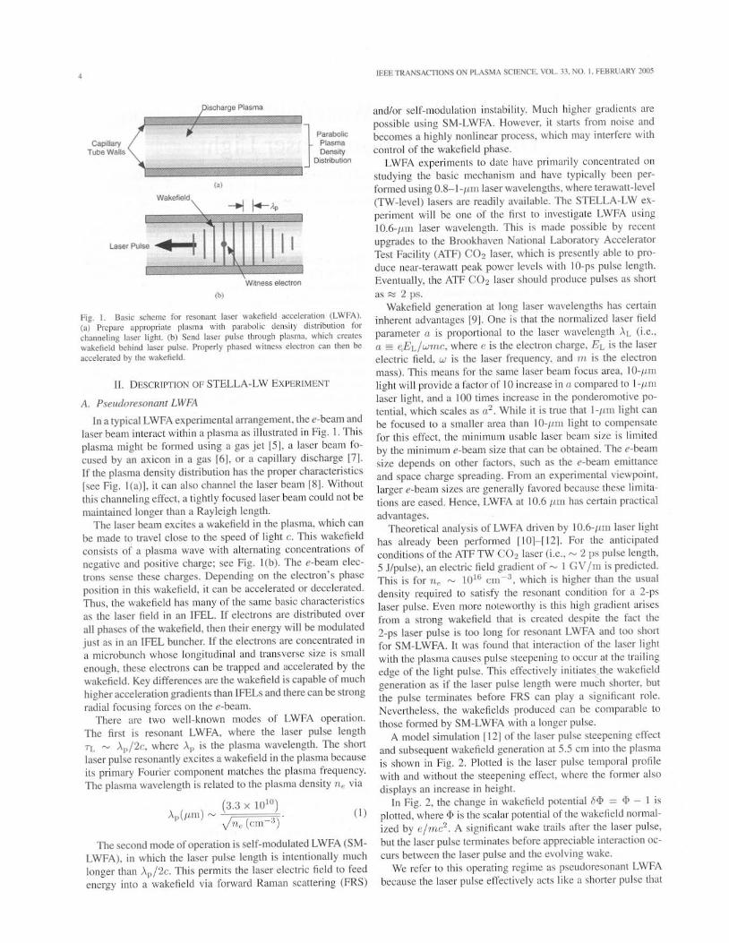
A model si mulation [12] of the 13ser pulse stcepening effect and subsequent wakefield generation at 5.5 cm into the plasma is shown in Fig. 2 . Plolted i ~ the laser pulsc temporal profile with and without the steepening effect. where the former also displays an increase in height.
In Fi g. 2, the change in wllkefield potential 6<1> :::: (I) - 1 is plotted. where (j) is the scalar potential of the wakefi e ld normal ized by e/mc2 . A significant wake trail s after the laser pulse, but the laser pu lse terminates before appreciable interaction occurs between the laser pulse and the e\'olving wake.
We refer to thi s operating regimc ag pseudorcsonant LWFA because the laser pulse effectively acts like it shorter pul se that
KIMURA el"I.: l'SEUDQRESQNAI'rr LASER WAKEFIELD AOCELER,HION
0 - 1.2 J'l ·c 1.0 " .e 0.8 ~ 0.6 .~
0.4 '" c 2 c 0.2
~ 0.0 Q)
'" '" --' -0.2
0
10
Laser intensity with pulse steepening
20
Laser intensity._-f'" without pulse stoopening
10 20
30
30
40 50 1.2
1.0
0.8
06
0.4
0.2
0.0
-0.2
40 50
;;:;; <5 " .9 e ~
Fig. 2. Laser pul<ot: intensity and change in wakefield poIelllial ,1<1> on axis (lines marked by cin::les) at propagation di.t;lncc:; 0;;: 5.S nil into the plasma 'ersus tile dimensionless COOfdinatc £: = l· .... (:; - ('1 ). ,,·here l ·po = ( 41H·~.\'olm )Ii1lc. e is eiL><:lron charge . .Yo is lhe unpcl1urbc<:! electron plasma densi1y. ," is the eleelron mas,. and I is time 1121. Dashed curve is the la~er il11cnsity without pulse ~teepcning . and thc solid curve is with pulsc steepening
would occur in resonant LWFA. This pulse-steepening phenomenon was also independently uncovered in [13[. published at the same time as [ 12J .
Because the laser pulse terminates before significant FRS growth occurs. aspects of SM-LWFA that are difficult to control may be mitigated. Thus. the wakc produced in the pscudoresonant regime may be more controllable. which would make it casier to stage the LWFA process.
8. Capillary Discharge
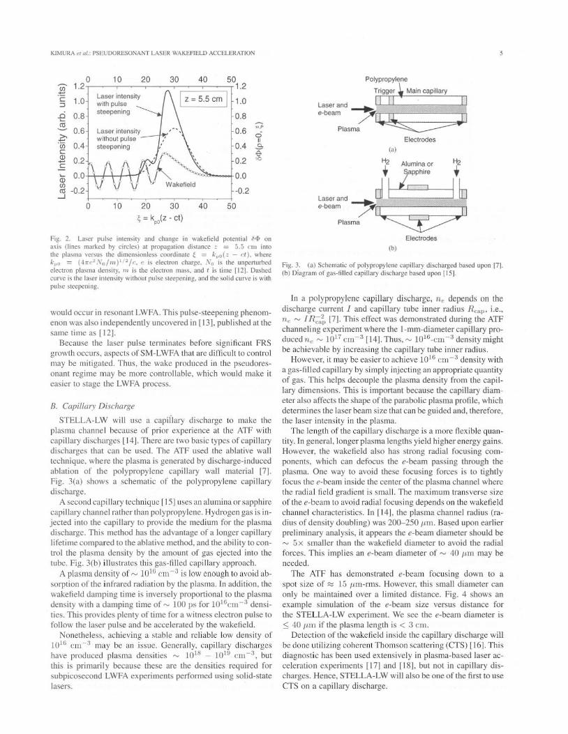
STELLA-LW will use a capiilary discharge to makc the plasma channel because of prior cxperience at the ATF with capillary discharges ll4 J. There arc two basic types of capillary dischargcs that can be used. The ATF used the ablative wall technique. where the plasma is generated by discharge-induced ablmion of the polypropylene capillary wall material [7]. Fig. 3(a) shows a schematic of the polypropylene capillary discharge.
A second capillary technique rl51 uses an alumina or sapphire capillary chan nel rathcr than polypropylene. Hydrogen gas is injected into the capillary 10 provide the medium for the plasma discharge . Thi s method has the advantage of a longer capillary lifetime compared to the ablative method, and the abi lity to control the plasma density by the amount of gas ejected into the tube. Fig. 3(b) illustrates this glls-filled capillary appronch.
A plasma den sity of ,.." lOW em - J is low enough to avoid absorption of the infrared radiation by the plasma. In addition. the wakefield damping time is inversely proponional to the plasma density with n damping time of...., 100 ps for 1016em - 3 densities. This provides plenty of time for a witness electron pulsc to follow the laser pu lse and be aceeler-lled by the wakefield.
Nonethel ess. achieving a stable and reliable low density of 10i6 ClU - J may be an issue. Generally, capillary discharges have produced plasma densities'"" 1018 - 1019 CII I - a , but this is primaril y because these arc the densities required for subpicosecond LWFA experiments performed using solid-state lasers.
5
Polypropylene
T,t'~i9~"~'~~M~'i~"~<a~.~.~I.~~~~~ Laserand ~
.-be~ 71~1 Ptasma ~
Electrodes (,)
'1 Alumina or '1 ' :::;' ,
L""'od _~1 16 e-beam /11 II
Plasma ~ Electrodes
(b)
Fig. 3. (a) Schematic of polypropylene capi llary discharged based upoo [71 (b) Dbgram of ga.-fi lled capillary di~charge ba>ed upon [1 51.
In a polypropylene capillary discharge, Up depends on the discharge currell! I and capillary tube inner radius R~"I" i.e. , n" '" I n;,,~ [7J. This effect was demonstrated during the ATF channeli ng experiment where the l-mm-diameter c:.lpillary produced n e ,.." [0 17 cm- 3 [14J. TI,US, '"" 1016~cm-3 density might be achievable by increasing the cllpi llary tube inner radi us.
However. it may be easier to achieve 1016 cl11 - 3 density with a gas-fi lied capillary by simply injecting an appropriate quantity of gas. This helps decouple the plasma density from the capillary dimensions. This is imponant because the capillary diameter also affects the shape of the paraoolie plasma profile. which determines the laser beam size that can be guided and, therefore. the laser intensity in the plasma.
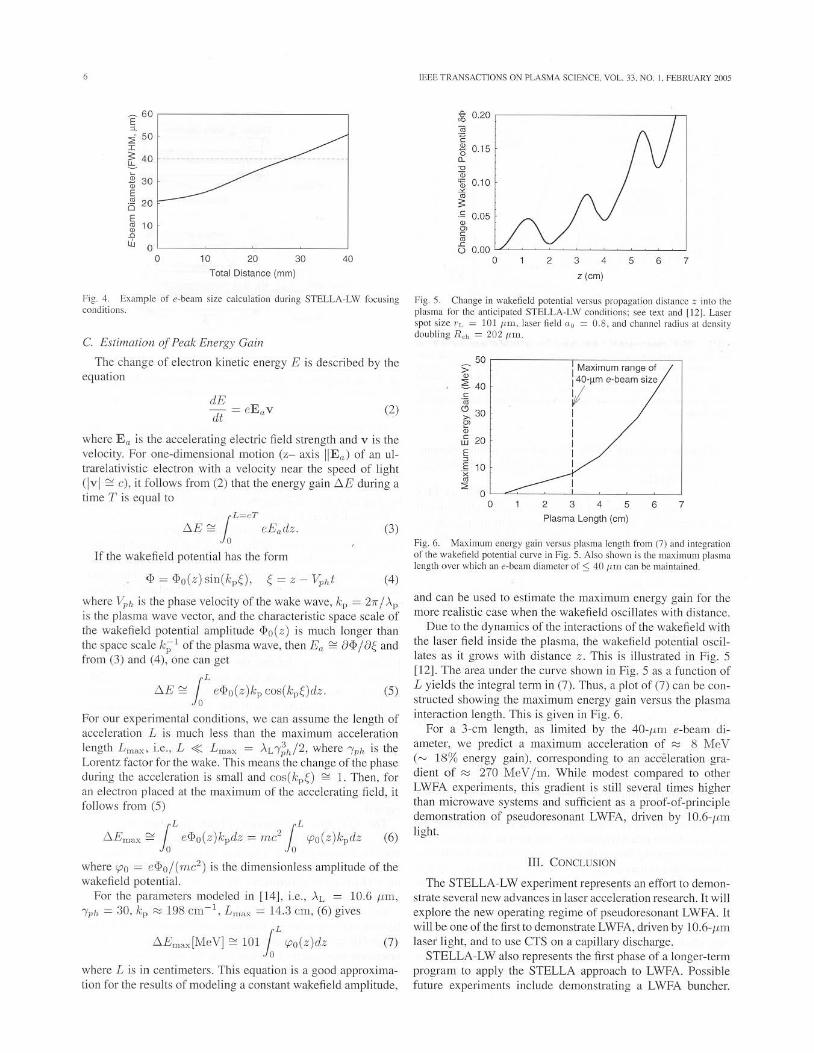
The length of the capillary discharge is a more Ilexible quantity. In general. longer plasma lengths yield higher energy gains. However. the wakefield also has strong mdial focusing components. which can defocus the e-beam passing through the plasma. One way to avoid these focusing forces is to tightly focus the e-beal1l inside the center of the plasma channel where the radial field grud ient is small. The maximum transverse size of the e-beam 10 avoid radial focusing depends on the wakefield channel characteristics. In f141. the plasma channel radius (radius of density doubling) was 200-250 l'lll. Based upon earlier preliminary analysis, it appears the e~beam diameter should be ""' 5x smaller than the wakefield diameter to avoid the radial forces. Thi s implies an e-bcam diameter of ,...., 40 Itnl may be needed.
The ATF has demonstrated e-beam focusing down to a spot size of:::::: 15 /tm-rms. However, this small diameter can only be maintained over a limited distance. Fig. 4 shows an example simulation of the e-beam size versus distance for the STELLA-LW experiment. We see the e-beam diameter is ~ 40 IlITl if the plasma length is < 3 CIll .
Detection of the wakefield inside the capillary discharge will be done utilizing coherent Thomson scattering (eTS) I J 61. This diagnostic has been used extensively in plasma-based laser acceleration experiments [17J and [18/. but not in capillary discharges. Hence. STELLA-LW will also be one of the first to use as on a capillary discharge.
6
~ 60 E , :i 50
" [ 40
* 30 E • 20
" E • 10 • • • 0 0 10 20 30 40
Total Distance (mm)
Fig_ 4 E~<lmplc of ,,-beam size calculation during STELLA-LW focusing conditions
C. £slimaliol1 of Peak Energy Gail!
The change of electron kinetic energy E is described by the equation
dE dt = eE"v (2)
where E" is the accelerating electric field strength and v is the velocity. For one-dimensional motion (z- axis IlE a) of an ultrarelativistic electron with a velocity near the speed of light (i v l ~ c). it follows from (2) that the energy gain t:::,.E during a time T is equal to
lL =CT
t::.E =:: eE"dz . . 0
(3)
[rthe wakefield potential has the form
<P = 'I) o(z)sill(kp~), ~ = z - Vpht (4)
where V ph is the phase velocity of the wake wave, kp = 2Jr / AI' is the plasma wave vector, and the characteristic space scale of the wakefield potential amplitude <po(z) is much longer than the space scale k]--;! of the plasma wave. then Ea ~ a~/ae and from (3) and (4), one can get
f:::.£ ~ lL c,j)o(z)kpcos(kpe)dz. (5)
For our experimental conditions, we can assume the length of acceleration L is much less than the maximum acceleration length Lmax . i.e .. L « L Illax = AL 1;/,/2, where Iph is the Lorentz factor for the wake. This means the change of the phase during the acceleration is small and cos(kpO <:::=: 1. Then. for an electron placed at the maximum of the accelerating held, it follows from (5)
rL rL f:::.Emax ~ io c<Po (z) kpdz::::; mc'2 in rpo(z)kpdz (6)
where rpo = c<Po/(nu;'2) is the dimensionless amplitude of the wakefield potential.
For the parameters modeled in [14 1. i.e., AL = 1O.6'WI, 'Yph = 30. kp ;::: 198 cm- I
. L",ax = 14.:1 CIll, (6) gives
f:::.E",ax [tv!eV ] <:::=: 101 lL l.Po(z)dz (7)
where [, is in centimeters. This equation is a good approximation for the results of modeling a constant wakefield amplitude,
IEEE TRANSACTIONS ON PLASMA SCIENCE. VOL. 33. NO. I. FEBRUARY 2005
j; 0 ,20 .. " ~ 0.15
" ~ ~ 0.10
• • , 0.05 • ~ 0 • " 0.00 u
0 2 3 4 5 6 7
z (em)
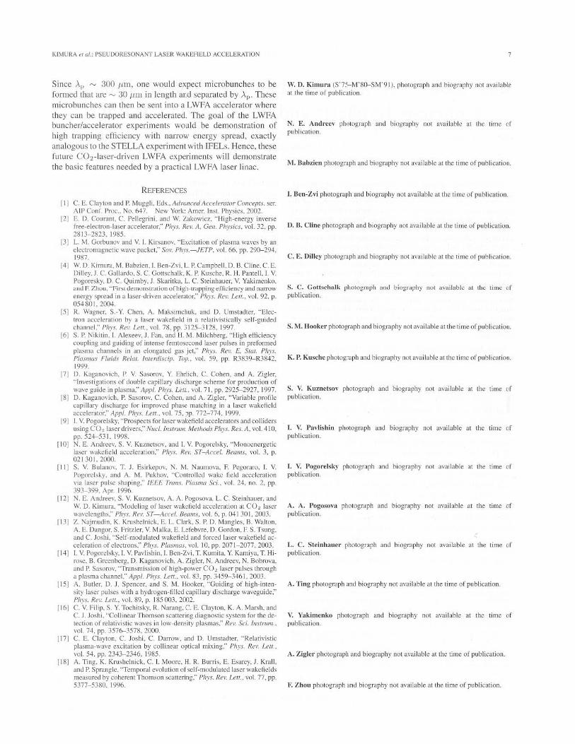
Fig, 5 Ch,mge in wakefield polenlial I'ersus propagalion dislancc z into Ihe plasma for the ant icip,ned STELLA-LW conditions: see tex t and 1121. Laser spot sizc "L = lOlllIll . laser fiel d "0 = 0.8. and channel radius lit density doub ling R ch = 202 1,m
50 '> I Maximum range, of • ~ 40
I 40-~m e-beam size
0 V 0
';, 30 I ~ I • I 0 20 w I E I 0 I , 10 , ro ,
0 0 2 3 4 5 6 7
Plasma Length (em)
Fig, 6 Maximum energy gain versus plasma length from (7) and integration of the w«kef'eld polemial curve in Fig. 5. Also shown is the maximum plasma length over whi~h an e·be'lm diameter of::; 4011111 can be main1ained.
and can be used 10 estimate the maximum energy gain for the more realistic case when the wakefield oscillates with distance.
Due to the dynamics of the imeraclions of the wakefield with the laser field inside the plasma, the wakefield potential oscil lates as it grows with distance z . Thi s is illustrated in Fig. 5 [l2j. The area under the curve shown in Fig. 5 as a function of L yields the integral term in (7) . Thus, a plot of (7) can be con structed showing the maximum energy gain versus the plasma interaction length . This is given in Fig. 6.
For a 3-cm length, as limited by the 40-lllll e-beam di amcter, we predict a maximum acceleration of;::: 8 NleV ("-' 18% energy gain), corresponding \0 an acceleration gradient of;::: 270 MeV /m. Whi le modest compared to other LWFA experiments, this gradient is sti ll several times higher than microwave systems and sufficiem as a proof-or-principle demonstration of pseudoresonant LWFA, driven by IO.6-flm light.
Ill. CONCLUSION
The STELLA LW experiment represents an effort to demonstratc several new advances in laser acceleration research. It wi ll explore the new operating regime or pseudoresonant LW FA. It will be one of the first to demonstrate LWFA, driven by IO.6-1I.1ll laser light, and to usc CTS on a capillary discharge.
STELLA-LW also represents the first phase of a longer-term program to apply the STELLA approach to LWFA. Possible future experiments include demonstrating a LWFA buncher.
KIMURA~' ~I., PSEUDORESONANT LASER WAKEFIELD ACCELERATION
Since Ap '" 300 /an, one would expect microbunches to be formed that are'" 30 ltm in length al;d separated by AI" These microbunches can Ihen be sent into a LWFA accelerator where they can be trapped and accelerated The goal of the LWi-'"'A buncher/accelerator experiments would be demonstration of high trapping efficiency with narrow energy spread, exactly analogous 10 Ihe STELLA experiment with IFELs. I-Icnce, these future CO2-laser-driven LWFA experiments will demonstrate the basic features needed by a practical LWFA laser linac.
REFERENCES
L I] C. E. Clayton and P. Muggli. Eds .. Ad,'('nced Acalemtor Cmu:e!'IS ser. AlP ConI. Proc .. No, 647 New York AmerlnSL Physics . 2002.
12 ] E. D. Cour~nL C. Pellegrini. and W. Zakowicz. "'High-energy inverse free-electron-laser acceleralOr:' Pill's. ReI'. A. GCfI. Physics. vol. 32. pp. 2813- 2823. 1985
13 ] L. M, Gorbunov and V. I. Ki rsanov. "Excitalion of plasma waves by an clcctronmgnClic wave packet:' 501'. Phy.,.-JF.TP. vol 66. pp. 29{l-294. 19117.
14 ] W D Kimura. M. Babzien.1. Ben-Zvi. L. p, Campt>cll. 0.13. Cline.C. E. Dilley.J, C. Gallardo. S , C. Gonschalk. K. P. Kusche. Kit , Pamell. j , V. Pogoresky. D, C. Quimby. J , Skaritb. L. C. Steinhauer. V. Yakimenko. ami F. Zh()u. "Fi"l dCIrl"""lrali"n orh iglHmpping effki~ncy ~nd narrow energy spre~d in a ]~ser-driven accele"llor:' Phys, Hel', I.'!II .. vol. 92. p. 054801. 2()Q.4..
15 ] K Wagner. S. -Y. Chen. A , Maksimchuk. and D. Um,tadter. "Electron acceleration by a laser wakefield in a relativistically self-guided channel:' Ph)",. ReI'. Len .. vol. 78. pp. 3125-3 ]28.1997
16] S P. Nikil;n. I. Ale~eev. J. Fan. ,md H. 1\1 , Mikht>crg. "High effic iency coupling .lnd guiding of intense femtos:cond laser pulses in preformed plasma channels in an elongated gas jet: ' Phys. ReI'. E. Stal. Ph),;. P{osmos Fluid.1 Relm, fnlen:lisdp. Top .. vol. 59. pp. R3839- R3S42. 1m
17J D. Kaganovieh . P. V Sasorov. Y Ehrlich. C. Cohen and A. Zigkr, "jnvest i g~tion s of double capil lary di><:harge scheme for producti on of wave guide in plasma:' lippi, PiJys. Lell.. vol. 71. pp, 2925- 2927. 1997.
18] D. Kaganovich.l'. Sasorov, C. Cohcn. and A. Zigler. "Variahle profi le capillary qiseharge for improved phase rn,llching in ,\ i;t;;n wakefield a,'eelerator:' API''- 1'11)'5. Lell .. \'01. 75. :lp, 772-774. 1999.
19 1 I. V. Pogorelsky. " Prospects for laser wakefield accelerators and colliders using CO2 laser drivers: ' N"d./llslmm, Melhods Phy.l. Res, A. vol. 4 10. pp. 524-531. 1998.
110] N. E. Andreev. S V Kuznetsov. and '- V Pogorelsky. "Monoenergetic' laser wakefield aceeler~il i on:' Phys. H(I'. ST-Arcet. Re(1l1ls. vol 3, p 021301,2000
Ill ] S, V. Bul.UlOV. 1'. J. Esirkepov. N. M. N.lUn10va. F. Pegoraro. V. Pogorelsky. and A. /1-'1 Pukhov. "Controlled wake field acceleration via laser pulse shaping: ' IEEE Tmlls Pi<,smo Sci .. vol. 24. no. 2. pp 393-399. Apr 1996
112 ] N. E. AndreeI'. S, V. Kuznetsov. A. A PogOSO\,.I . L. C. Steinhauer. and W. D. Kimura. "Modeling of laser wakefield accelerat ion at CO2 laser wavelengths:' Phy.l . Hn'. ST -Ac<:el. 8m1ll.l', 1'0L 6. p. D4] 301. 20(H
113 ] Z N~jmudin. K. Krushelnick. E LClark. S P D Mangles. B. W~l ton .
A, E. Dangor. S , Frillier. V. M,ilka. E. L~febvre. D, Gordon. F. S. Tsung. and C. Joshi. "Self-modulated wakefiel:l and forced laser wakefield ac · celeration of electrons: ' Phys. Plasmas. vol. I D. pp. 2071- 2077. 2003.
114] I. V Pogorelsky. I. V Pavlishin. I. Ben-Zvi. T Kumita. Y. Kamiya. T Hirose. B. Greenberg. D . Kaganovich . A. Zigler. N. AndreeI'. N. Bobrova. and P. S~soro\'. '"Transmission of high-power CO'l laser pul,es through a plasm.l channel." Appl. I'h),s, UII .. V{,I. 83. pp. 3459-346 1. 2003
1151 A. Butler. D , J. Spencer. and S. M. Hooker. ""Goiding of high-intensi ty lascr pulses with ~ hydrogen-filled capillary discharge waveguide:' Phys. ReI'. Dm .. \,oL 89. p. 185003. 2002
1161 C. v. Filip. S. Y. Tochitsky. R, Narang. C. E. Clayton. K, A. Marsh. and C. J. Joshi. "Collincar Thomson scattering diagnostic system for the dctection of relativ istic w~ves in l ow - den~ity JlI~smas:' Rev. Sci. !"-'Imm .. '01. 74, pp. 3576---3578. 2000
1171 c. E. Clayton. C. Joshi. C. Darrow. "nd O. Um,t Jdter. ""Relativislic plasma·wave excitation by collinear opticat mi ~ing:' I'h),s, Rev. Lell .. vol. 54. pp. 2343- 2346. 1985.
[ Ill] A. Ting. K. Krushclnick. C.l , Moore. H, R , Burris. E. Esarey.J , Krall. and P Spranglc. '"Temporal evolution of self-modulated laser wakefields measured by coherent Thomson >callering:' Phys. Hel'. Lell . vol. 77> pp 5377- 5380. 1996.
W. D. K imura (S·75-M·80-S1\1·91). photograph and biography not available at the tim~ of publ ic~lion.
N. E. Andr<:c, phutograph and biography not available at the time 01' publication
ill. Babzien photograph and biography not available allhe lime of publication.
t. Ben-Zvi photograph and biography not available at the lime of publication
D. B. Cline photograph and biography not ~\'ai ]~ble at the lime of publication
C. E. Dilley phOlograph and biography not avai lable at the time of publication
S. C. CoUseh"lk phOlograph und biogn,phy nol available at the time i'f publication.
S.1\I. Hooker photo£raph and biography not available at the time of public~tion.
K. 1'. Kusche photog-aph lind biography not .l\,.l ilable at the ti me of publication.
S. V. Ku ztwlsoy photograph and biography not available ~I Ihe time ()f publication.
I. V. P;wli shin photograph and biography not avai lable at the time {)f pllbl ic~li()n
t. V. Pogorelsky photograph and biography not available at the time {)f publication.
A. A . I'ogoso,'a phOlOg r~ph and bi ogr~phy not available at the time (of publi(.·"tion
L. C. Steinhauer photograph and biography not available at the time of publication
A. Ting photogr~ph and biogr~phy nOl av~ilable at Ihe lime of public'llion.
V. Yakimenko phulograp h and biography nol available at Ihe time of publication
A. Zigler photograph and biography not avai lable at the ti me of publication.
F. Zhou photograph ilnd biography nol avai b ble '1llhe time of publ ication.