iec 60950 3rd edition with comments. - pulspower.com · equipment is non-protected according to iec...
TRANSCRIPT


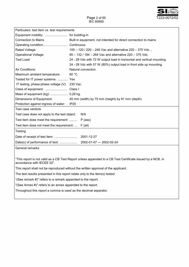
Page 2 of 85 T223-0072/02 IEC 60950 Particulars: test item vs. test requirements Equipment mobility: .......................... for building-in Connection to Mains Built in equipment, not intended for direct connection to mains Operating condition:........................... Continuous Rated Voltage: 100 � 120 / 220 � 240 Vac and alternative 220 � 375 Vdc. , Operational Voltage: 85 � 132 / 184 � 264 Vac and alternative 220 � 375 Vdc. Test Load: 24 - 28 Vdc with 72 W output load in horizontal and vertical mounting
24 - 28 Vdc with 57 W (80%) output load in front side up mounting. Air Conditions: Natural convection. Maximum ambient temperature: 60 °C Tested for IT power systems: ........... Yes IT testing, phase-phase voltage (V): 230 Vac. Class of equipment: .......................... Class I Mass of equipment (kg): .................... 0,26 kg. Dimensions of Equipment: 45 mm (width) by 75 mm (height) by 91 mm (depth) Protection against ingress of water: . IP20 Test case verdicts Test case does not apply to the test object: N/A
Test item does meet the requirement: ......... P (ass)
Test item does not meet the requirement: ... F (ail)
Testing
Date of receipt of test item: .......................... 2001-12-27
Date(s) of performance of test: .................... 2002-01-07 � 2002-02-24
General remarks
�This report is not valid as a CB Test Report unless appended to a CB Test Certificate issued by a NCB, in accordance with IECEE 02�.
This report shall not be reproduced without the written approval of the applicant.
The test results presented in this report relate only to the item(s) tested.
�(See remark #)" refers to a remark appended to the report.
"(See Annex #)" refers to an annex appended to the report.
Throughout this report a comma is used as the decimal separator.
Page 3 of 85 T223-0072/02 IEC 60950
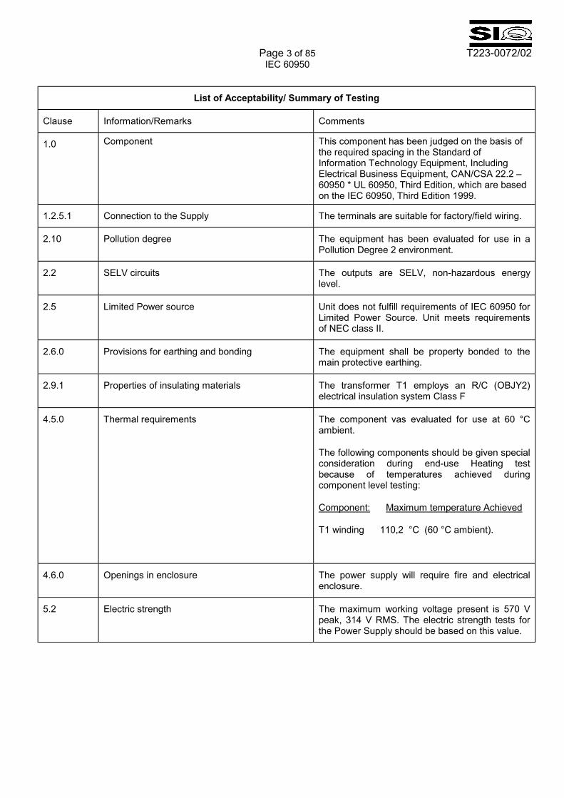
List of Acceptability/ Summary of Testing
Clause Information/Remarks Comments
1.0 Component This component has been judged on the basis of the required spacing in the Standard of Information Technology Equipment, Including Electrical Business Equipment, CAN/CSA 22.2 � 60950 * UL 60950, Third Edition, which are based on the IEC 60950, Third Edition 1999.
1.2.5.1 Connection to the Supply The terminals are suitable for factory/field wiring.
2.10 Pollution degree The equipment has been evaluated for use in a Pollution Degree 2 environment.
2.2 SELV circuits The outputs are SELV, non-hazardous energy level.
2.5 Limited Power source Unit does not fulfill requirements of IEC 60950 for Limited Power Source. Unit meets requirements of NEC class II.
2.6.0 Provisions for earthing and bonding The equipment shall be property bonded to the main protective earthing.
2.9.1 Properties of insulating materials The transformer T1 employs an R/C (OBJY2) electrical insulation system Class F
4.5.0 Thermal requirements The component vas evaluated for use at 60 °C ambient.
The following components should be given special consideration during end-use Heating test because of temperatures achieved during component level testing:
Component: Maximum temperature Achieved
T1 winding 110,2 °C (60 °C ambient).
4.6.0 Openings in enclosure The power supply will require fire and electrical enclosure.
5.2 Electric strength The maximum working voltage present is 570 V peak, 314 V RMS. The electric strength tests for the Power Supply should be based on this value.
Page 4 of 85 T223-0072/02 IEC 60950
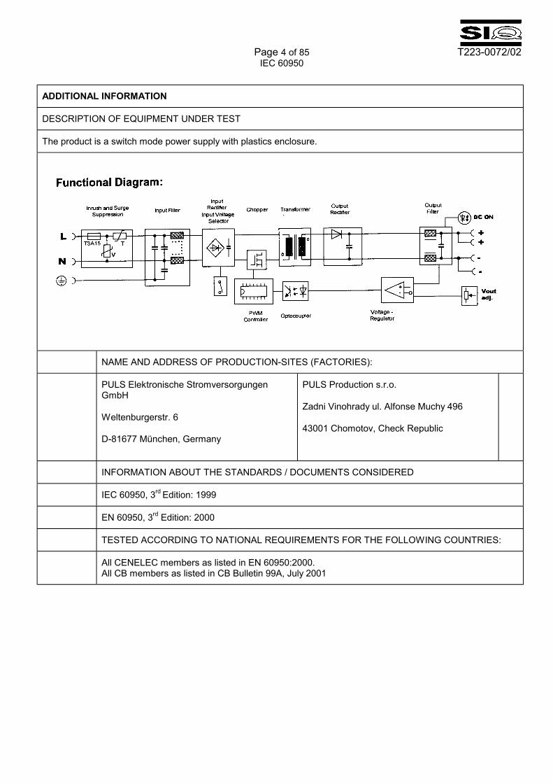
ADDITIONAL INFORMATION
DESCRIPTION OF EQUIPMENT UNDER TEST
The product is a switch mode power supply with plastics enclosure.
NAME AND ADDRESS OF PRODUCTION-SITES (FACTORIES):
PULS Elektronische Stromversorgungen GmbH
Weltenburgerstr. 6
D-81677 München, Germany
PULS Production s.r.o.
Zadni Vinohrady ul. Alfonse Muchy 496
43001 Chomotov, Check Republic
INFORMATION ABOUT THE STANDARDS / DOCUMENTS CONSIDERED
IEC 60950, 3rd Edition: 1999
EN 60950, 3rd Edition: 2000
TESTED ACCORDING TO NATIONAL REQUIREMENTS FOR THE FOLLOWING COUNTRIES:
All CENELEC members as listed in EN 60950:2000. All CB members as listed in CB Bulletin 99A, July 2001
Page 5 of 85 T223-0072/02 IEC 60950
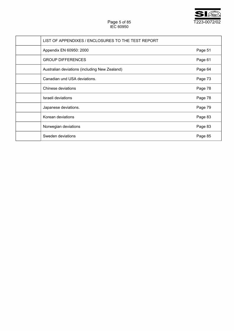
LIST OF APPENDIXES / ENCLOSURES TO THE TEST REPORT
Appendix EN 60950: 2000 Page 51
GROUP DIFFERENCES Page 61
Australian deviations (including New Zealand) Page 64
Canadian und USA deviations. Page 73
Chinese deviations Page 78
Israeli deviations Page 78
Japanese deviations. Page 79
Korean deviations Page 83
Norwegian deviations Page 83
Sweden deviations Page 85
Page 6 of 85 T223-0072/02
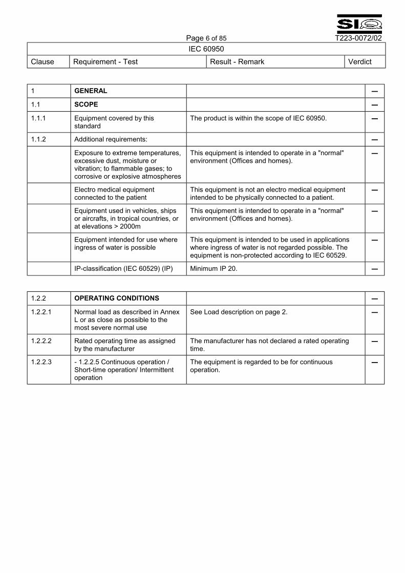
IEC 60950 Clause Requirement - Test Result - Remark Verdict 1 GENERAL �
1.1 SCOPE �
1.1.1 Equipment covered by this standard
The product is within the scope of IEC 60950. �
1.1.2 Additional requirements: �
Exposure to extreme temperatures, excessive dust, moisture or vibration; to flammable gases; to corrosive or explosive atmospheres
This equipment is intended to operate in a "normal" environment (Offices and homes).
�
Electro medical equipment connected to the patient
This equipment is not an electro medical equipment intended to be physically connected to a patient.
�
Equipment used in vehicles, ships or aircrafts, in tropical countries, or at elevations > 2000m
This equipment is intended to operate in a "normal" environment (Offices and homes).
�
Equipment intended for use where ingress of water is possible
This equipment is intended to be used in applications where ingress of water is not regarded possible. The equipment is non-protected according to IEC 60529.
�
IP-classification (IEC 60529) (IP) Minimum IP 20. � 1.2.2 OPERATING CONDITIONS �
1.2.2.1 Normal load as described in Annex L or as close as possible to the most severe normal use
See Load description on page 2. �
1.2.2.2 Rated operating time as assigned by the manufacturer
The manufacturer has not declared a rated operating time.
�
1.2.2.3 - 1.2.2.5 Continuous operation / Short-time operation/ Intermittent operation
The equipment is regarded to be for continuous operation.
�

Page 7 of 85 T223-0072/02
IEC 60950 Clause Requirement - Test Result - Remark Verdict
1.5 COMPONENTS P
1.5.1 General Ref. List of Critical Components. P
1.5.2 Evaluation and testing of components
Certified components are used in accordance with their ratings, certifications and they comply with applicable parts of this standard. Components not certified are used in accordance with their ratings and they comply with applicable parts of IEC 60950 and the relevant component standard. Components, for which no relevant IEC-standard exists, have been tested under the conditions occurring in the equipment, using applicable parts of IEC 60950.
P
Dimensions of mains plug for direct plug-in equipment
Not a direct plug-in equipment. N
Additional torque (Nm) Pull (N)
N
1.5.3 Thermal controls No thermal controls. N
1.5.4 Transformers Transformers used are suitable for their intended applications and comply with relevant parts of this standard and particularly Annex C, see Annex C � Transformers.
P
1.5.5 Interconnecting cables No interconnecting cables. N
1.5.6 Capacitors in primary circuits X1 or X2 and Y1 or Y2 capacitors according to IEC 60384-14:1993. P
1.5.7.1 - 1.5.7.3 Double or reinforced insulation bridged by components
No such components bridging double or reinforced insulation.
N
1.5.8 Components in equipment for IT power systems
The components were evaluated and passed the requirements.
P
1.5 LIST OF CRITICAL COMPONENTS P
See enclosed test results.
1.6 POWER INTERFACE P
1.6.1 A.C. power distribution systems TN and IT for 230 Vac �
1.6.2 Input current 1,6A / 0,8 A �
Test voltage (at each rated voltage or at each end of a rated voltage range)
100 � 240 Vac
220 � 375 Vdc
�
Measured current Refer to enclosed test results �
Deviation The input current measured is below 1,1 times of the rated current.
P
Page 8 of 85 T223-0072/02
IEC 60950 Clause Requirement - Test Result - Remark Verdict
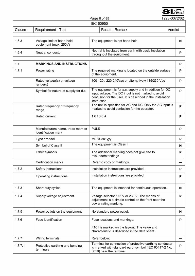
1.6.3 Voltage limit of hand-held equipment (max. 250V)
The equipment is not hand-held. N
1.6.4 Neutral conductor Neutral is insulated from earth with basic insulation throughout the equipment. P
1.7 MARKINGS AND INSTRUCTIONS P
1.7.1 Power rating The required marking is located on the outside surface of the equipment.
P
Rated voltage(s) or voltage range(s)
100-120 / 220-240Vac or alternatively 115/230 Vac P
Symbol for nature of supply for d.c. The equipment is for a.c. supply and in addition for DC input voltage. The DC input is not marked to avoid confusion for the user. It is described in the installation instruction.
P
Rated frequency or frequency range
The unit is specified for AC and DC. Only the AC input is marked to avoid confusion for the operator.
P
Rated current 1,6 / 0,8 A
P
Manufacturers name, trade mark or identification mark
PULS P
Type / model ML70.xxx-yyy P
Symbol of Class II The equipment is Class I. N
Other symbols The additional marking does not give rise to misunderstandings.
P
Certification marks Refer to copy of markings. �
1.7.2 Safety instructions Installation instructions are provided. P
Operating instructions
Installation instructions are provided. P
1.7.3 Short duty cycles The equipment is intended for continuous operation. N
1.7.4 Supply voltage adjustment Voltage selector 115 V or 230 V. The means of adjustment is a simple control on the front near the power rating marking.
P
1.7.5 Power outlets on the equipment No standard power outlet. N
1.7.6 Fuse identification Fuse locations and markings:
F101 is marked on the lay-out. The value and characteristic is described in the data sheet.
P
1.7.7 Wiring terminals Refer below: �
1.7.7.1 Protective earthing and bonding terminals
Terminal for connection of protective earthing conductor is marked with standard earth symbol (IEC 60417-2 No. 5019) near the terminal.
P
Page 9 of 85 T223-0072/02
IEC 60950 Clause Requirement - Test Result - Remark Verdict
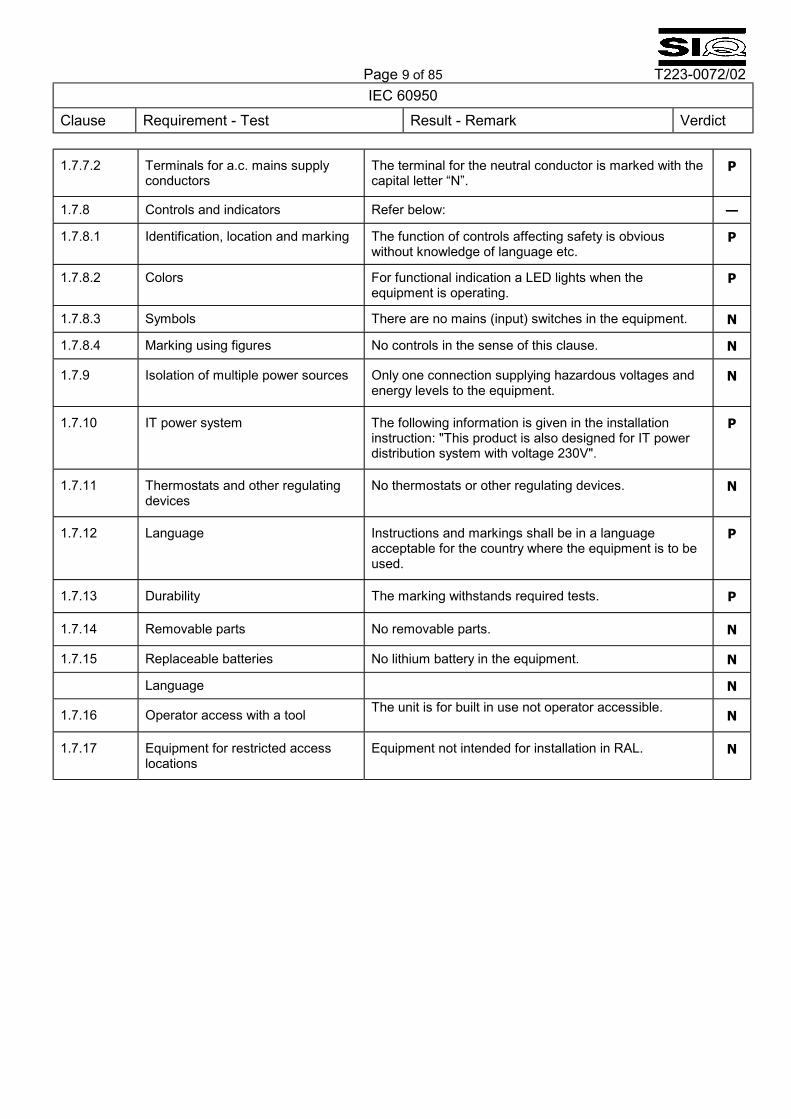
1.7.7.2 Terminals for a.c. mains supply conductors
The terminal for the neutral conductor is marked with the capital letter �N�.
P
1.7.8 Controls and indicators Refer below: �
1.7.8.1 Identification, location and marking The function of controls affecting safety is obvious without knowledge of language etc.
P
1.7.8.2 Colors For functional indication a LED lights when the equipment is operating.
P
1.7.8.3 Symbols There are no mains (input) switches in the equipment. N
1.7.8.4 Marking using figures No controls in the sense of this clause. N
1.7.9 Isolation of multiple power sources Only one connection supplying hazardous voltages and energy levels to the equipment.
N
1.7.10 IT power system The following information is given in the installation instruction: "This product is also designed for IT power distribution system with voltage 230V".
P
1.7.11 Thermostats and other regulating devices
No thermostats or other regulating devices. N
1.7.12 Language Instructions and markings shall be in a language acceptable for the country where the equipment is to be used.
P
1.7.13 Durability The marking withstands required tests. P
1.7.14 Removable parts No removable parts. N
1.7.15 Replaceable batteries No lithium battery in the equipment. N
Language N
1.7.16 Operator access with a tool The unit is for built in use not operator accessible. N
1.7.17 Equipment for restricted access locations
Equipment not intended for installation in RAL. N
Page 10 of 85 T223-0072/02
IEC 60950 Clause Requirement - Test Result - Remark Verdict
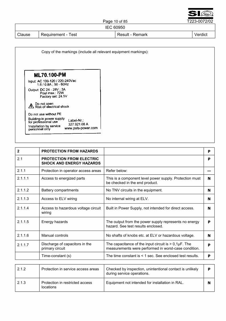
Copy of the markings (include all relevant equipment markings):
2 PROTECTION FROM HAZARDS P
2.1 PROTECTION FROM ELECTRIC SHOCK AND ENERGY HAZARDS
P
2.1.1 Protection in operator access areas Refer below: �
2.1.1.1 Access to energized parts This is a component level power supply. Protection must be checked in the end product.
N
2.1.1.2 Battery compartments No TNV circuits in the equipment. N
2.1.1.3 Access to ELV wiring No internal wiring at ELV. N
2.1.1.4 Access to hazardous voltage circuit wiring
Built in Power Supply, not intended for direct access. N
2.1.1.5 Energy hazards The output from the power supply represents no energy hazard. See test results enclosed.
P
2.1.1.6 Manual controls No shafts of knobs etc. at ELV or hazardous voltage. N
2.1.1.7 Discharge of capacitors in the primary circuit
The capacitance of the input circuit is > 0,1µF. The measurements were performed in worst-case condition.
P
Time-constant (s) The time constant is < 1 sec. See enclosed test results. P
2.1.2 Protection in service access areas Checked by inspection, unintentional contact is unlikely during service operations.
P
2.1.3 Protection in restricted access locations
Equipment not intended for installation in RAL. N

Page 11 of 85 T223-0072/02
IEC 60950 Clause Requirement - Test Result - Remark Verdict
2.2 SELV CIRCUITS P
2.2.1 General requirements SELV limits (at accessible parts) are not exceeded under normal condition and after a single fault.
P
2.2.2 Voltages under normal conditions Within SELV limits. (See enclosed test results) P
2.2.3 Voltage under fault conditions Single fault conditions: <60 Vdc P
2.2.3.1 - 2.2.3.3 Method used for separation
Method 1 P
2.2.4 Connection of SELV circuits to other circuits
SELV circuits are only connected to hazardous voltages in secondary circuits, but accessible parts do not exceed the limits of SELV in the event of a single failure of a component or shorting of functional insulation not complying with the requirements.
P
2.3 TNV CIRCUITS 2.3.1 � 2.3.5; No TNV circuits in the equipment. N 2.4 LIMITED CURRENT CIRCUITS 2.4.1 � 2.4.3; No limited current circuits. N 2.5 LIMITED POWER SOURCES Unit meets requirements of NEC class II. N 2.6 PROVISIONS FOR EARTHING
AND BONDING The built in equipment shall be properly bonded to the main protective earthing.
P
2.6.1 Protective earthing The unit is for built in. The enclosure is not intended for operator contact: The enclosure is made of plastic.
P
Warning label for service personnel. Warning label:
The following warning notice is written on the type label: �DO NOT USE WITHOUT PE�.
P
2.6.2 Functional earthing No functional earthing is provided. N
2.6.3 Protective earthing and protective bonding conductors
Refer below: �
2.6.3.1 Size of protective earthing conductors
Rated current of the circuit under test: 1,6 A. Terminal is rated for 0,5 � 2,5 mm2/ 20 � 12 AWG. P
2.6.3.2 Size of protective bonding conductors
See clause 2.6.3.3 P
2.6.3.3 Resistance of earthing conductors and their terminations
From the earth terminal to the chassis : (see below) P
Test current See enclosed test results. P
2.6.3.4 Color of insulation The built in Power Supply does not provide wiring (for earthing. N
2.6.4 Terminals Refer below: �
2.6.4.1 Protective earthing and bonding terminals
Rated current of equipment: 1,6 A. Cross sectional area: 0,5 � 2,5 mm2. / 20 � 12 AWG P
Page 12 of 85 T223-0072/02
IEC 60950 Clause Requirement - Test Result - Remark Verdict
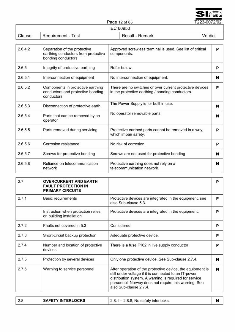
2.6.4.2 Separation of the protective earthing conductors from protective bonding conductors
Approved screwless terminal is used. See list of critical components.
P
2.6.5 Integrity of protective earthing Refer below: P
2.6.5.1 Interconnection of equipment No interconnection of equipment. N
2.6.5.2 Components in protective earthing conductors and protective bonding conductors
There are no switches or over current protective devices in the protective earthing / bonding conductors.
P
2.6.5.3 Disconnection of protective earth The Power Supply is for built in use. N
2.6.5.4 Parts that can be removed by an operator
No operator removable parts. N
2.6.5.5 Parts removed during servicing Protective earthed parts cannot be removed in a way, which impair safety.
P
2.6.5.6 Corrosion resistance No risk of corrosion. P
2.6.5.7 Screws for protective bonding Screws are not used for protective bonding N
2.6.5.8 Reliance on telecommunication network
Protective earthing does not rely on a telecommunication network.
N
2.7 OVERCURRENT AND EARTH
FAULT PROTECTION IN PRIMARY CIRCUITS
P
2.7.1 Basic requirements Protective devices are integrated in the equipment, see also Sub-clause 5.3.
P
Instruction when protection relies on building installation
Protective devices are integrated in the equipment. P
2.7.2 Faults not covered in 5.3 Considered. P
2.7.3 Short-circuit backup protection Adequate protective device. P
2.7.4 Number and location of protective devices
There is a fuse F102 in live supply conductor. P
2.7.5 Protection by several devices Only one protective device. See Sub-clause 2.7.4. N
2.7.6 Warning to service personnel After operation of the protective device, the equipment is still under voltage if it is connected to an IT-power distribution system. A warning is required for service personnel. Norway does not require this warning. See also Sub-clause 2.7.4.
N
2.8 SAFETY INTERLOCKS 2.8.1 � 2.8.8; No safety interlocks. N
Page 13 of 85 T223-0072/02
IEC 60950 Clause Requirement - Test Result - Remark Verdict
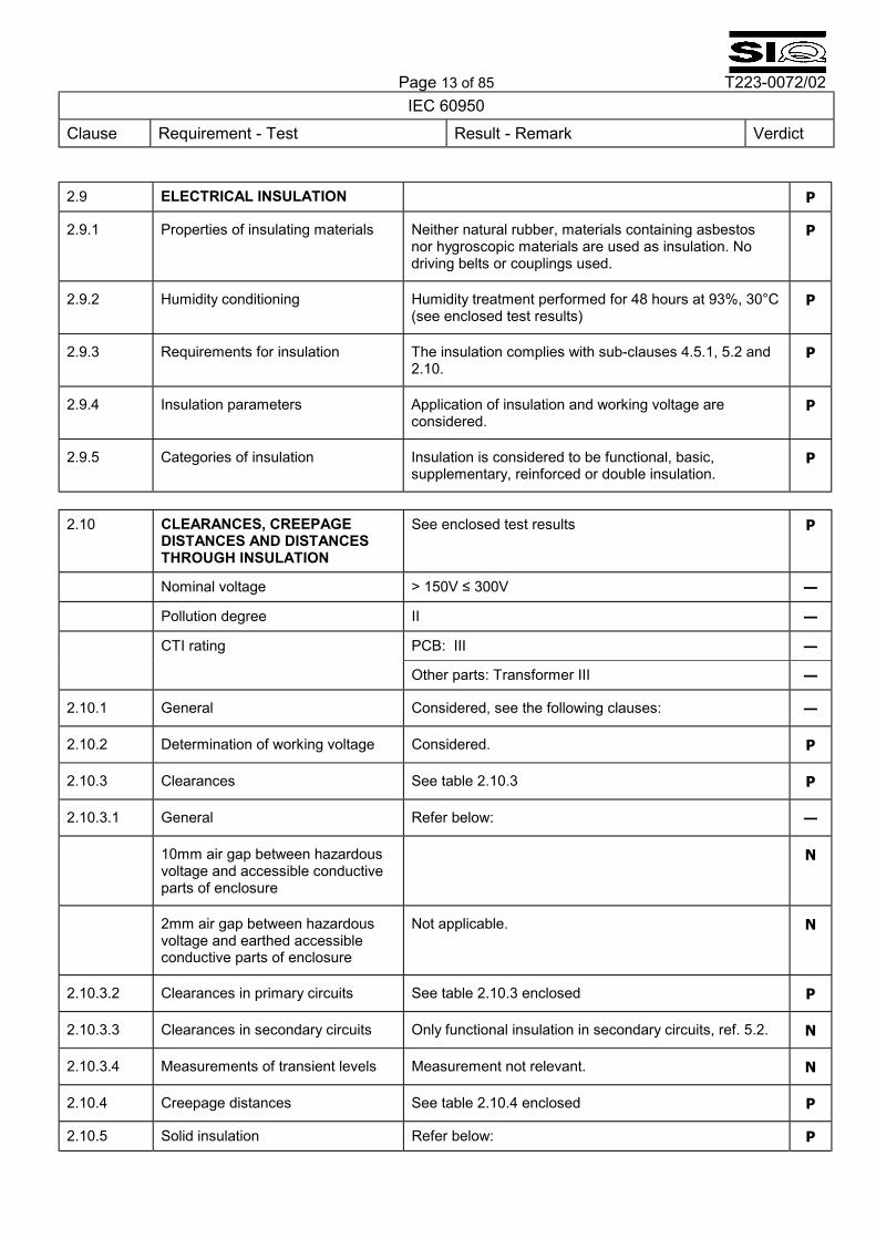
2.9 ELECTRICAL INSULATION P
2.9.1 Properties of insulating materials Neither natural rubber, materials containing asbestos nor hygroscopic materials are used as insulation. No driving belts or couplings used.
P
2.9.2 Humidity conditioning Humidity treatment performed for 48 hours at 93%, 30°C (see enclosed test results)
P
2.9.3 Requirements for insulation The insulation complies with sub-clauses 4.5.1, 5.2 and 2.10.
P
2.9.4 Insulation parameters Application of insulation and working voltage are considered.
P
2.9.5 Categories of insulation Insulation is considered to be functional, basic, supplementary, reinforced or double insulation.
P
2.10 CLEARANCES, CREEPAGE
DISTANCES AND DISTANCES THROUGH INSULATION
See enclosed test results P
Nominal voltage > 150V ≤ 300V �
Pollution degree II �
CTI rating PCB: III �
Other parts: Transformer III �
2.10.1 General Considered, see the following clauses: �
2.10.2 Determination of working voltage Considered. P
2.10.3 Clearances See table 2.10.3 P
2.10.3.1 General Refer below: �
10mm air gap between hazardous voltage and accessible conductive parts of enclosure
N
2mm air gap between hazardous voltage and earthed accessible conductive parts of enclosure
Not applicable. N
2.10.3.2 Clearances in primary circuits See table 2.10.3 enclosed P
2.10.3.3 Clearances in secondary circuits Only functional insulation in secondary circuits, ref. 5.2. N
2.10.3.4 Measurements of transient levels Measurement not relevant. N
2.10.4 Creepage distances See table 2.10.4 enclosed P
2.10.5 Solid insulation Refer below: P
Page 14 of 85 T223-0072/02
IEC 60950 Clause Requirement - Test Result - Remark Verdict
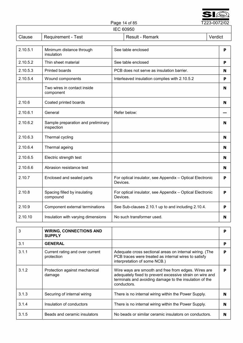
2.10.5.1 Minimum distance through insulation
See table enclosed P
2.10.5.2 Thin sheet material See table enclosed P
2.10.5.3 Printed boards PCB does not serve as insulation barrier. N
2.10.5.4 Wound components Interleaved insulation complies with 2.10.5.2 P
Two wires in contact inside component
N
2.10.6 Coated printed boards N
2.10.6.1 General Refer below: �
2.10.6.2 Sample preparation and preliminary inspection
N
2.10.6.3 Thermal cycling N
2.10.6.4 Thermal ageing N
2.10.6.5 Electric strength test N
2.10.6.6 Abrasion resistance test N
2.10.7 Enclosed and sealed parts For optical insulator, see Appendix � Optical Electronic Devices.
P
2.10.8 Spacing filled by insulating compound
For optical insulator, see Appendix � Optical Electronic Devices.
P
2.10.9 Component external terminations See Sub-clauses 2.10.1 up to and including 2.10.4. P
2.10.10 Insulation with varying dimensions No such transformer used. N
3 WIRING, CONNECTIONS AND
SUPPLY P
3.1 GENERAL P
3.1.1 Current rating and over current protection
Adequate cross sectional areas on internal wiring. (The PCB traces were treated as internal wires to satisfy interpretation of some NCB.)
P
3.1.2 Protection against mechanical damage
Wire ways are smooth and free from edges. Wires are adequately fixed to prevent excessive strain on wire and terminals and avoiding damage to the insulation of the conductors.
P
3.1.3 Securing of internal wiring There is no internal wiring within the Power Supply. N
3.1.4 Insulation of conductors There is no internal wiring within the Power Supply. N
3.1.5 Beads and ceramic insulators No beads or similar ceramic insulators on conductors. N
Page 15 of 85 T223-0072/02
IEC 60950 Clause Requirement - Test Result - Remark Verdict
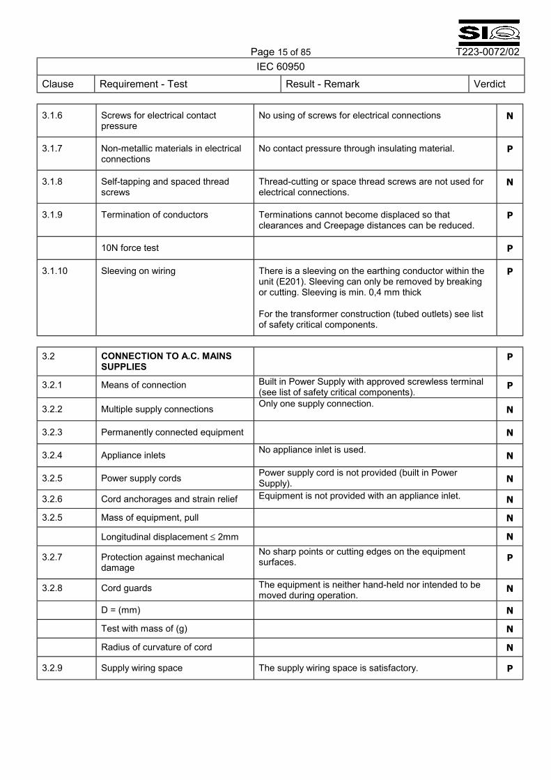
3.1.6 Screws for electrical contact pressure
No using of screws for electrical connections N
3.1.7 Non-metallic materials in electrical connections
No contact pressure through insulating material. P
3.1.8 Self-tapping and spaced thread screws
Thread-cutting or space thread screws are not used for electrical connections.
N
3.1.9 Termination of conductors Terminations cannot become displaced so that clearances and Creepage distances can be reduced.
P
10N force test P
3.1.10 Sleeving on wiring There is a sleeving on the earthing conductor within the unit (E201). Sleeving can only be removed by breaking or cutting. Sleeving is min. 0,4 mm thick
For the transformer construction (tubed outlets) see list of safety critical components.
P
3.2 CONNECTION TO A.C. MAINS
SUPPLIES P
3.2.1 Means of connection Built in Power Supply with approved screwless terminal (see list of safety critical components).
P
3.2.2 Multiple supply connections Only one supply connection. N
3.2.3 Permanently connected equipment N
3.2.4 Appliance inlets No appliance inlet is used. N
3.2.5 Power supply cords Power supply cord is not provided (built in Power Supply). N
3.2.6 Cord anchorages and strain relief Equipment is not provided with an appliance inlet. N
3.2.5 Mass of equipment, pull N
Longitudinal displacement ≤ 2mm N
3.2.7 Protection against mechanical damage
No sharp points or cutting edges on the equipment surfaces. P
3.2.8 Cord guards The equipment is neither hand-held nor intended to be moved during operation.
N
D = (mm) N
Test with mass of (g) N
Radius of curvature of cord N
3.2.9 Supply wiring space The supply wiring space is satisfactory. P
Page 16 of 85 T223-0072/02
IEC 60950 Clause Requirement - Test Result - Remark Verdict
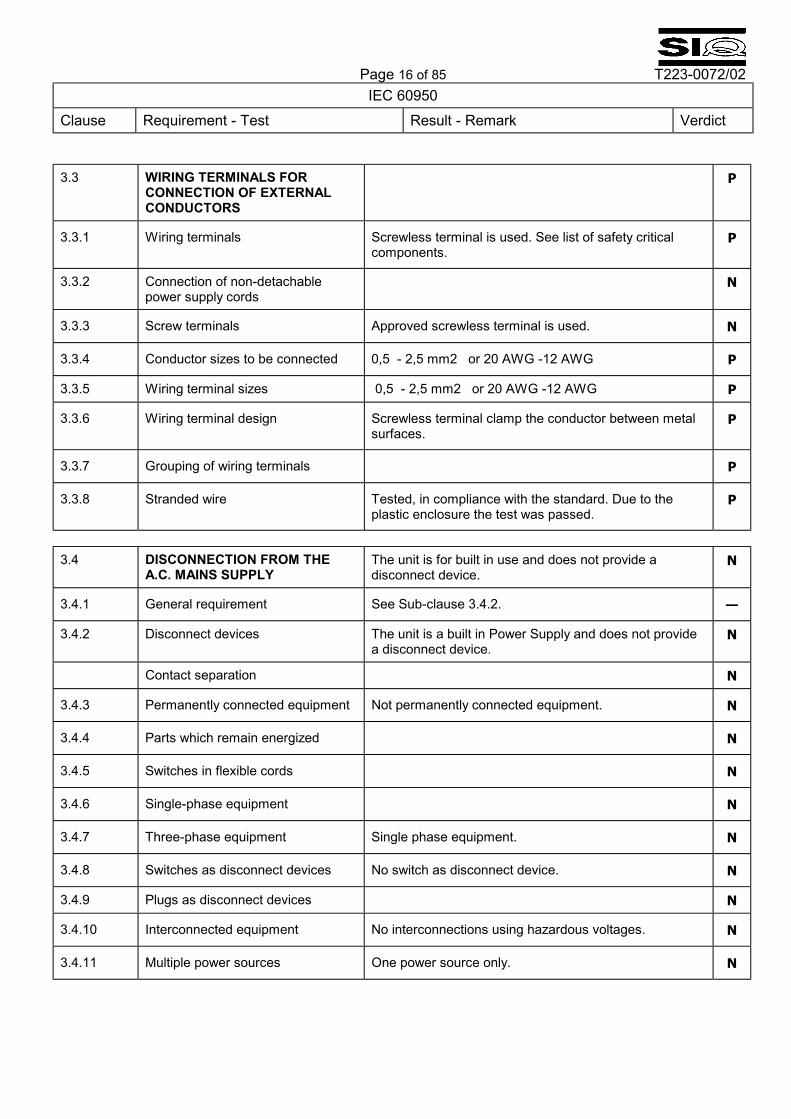
3.3 WIRING TERMINALS FOR
CONNECTION OF EXTERNAL CONDUCTORS
P
3.3.1 Wiring terminals Screwless terminal is used. See list of safety critical components.
P
3.3.2 Connection of non-detachable power supply cords
N
3.3.3 Screw terminals Approved screwless terminal is used. N
3.3.4 Conductor sizes to be connected 0,5 - 2,5 mm2 or 20 AWG -12 AWG P
3.3.5 Wiring terminal sizes 0,5 - 2,5 mm2 or 20 AWG -12 AWG P
3.3.6 Wiring terminal design Screwless terminal clamp the conductor between metal surfaces.
P
3.3.7 Grouping of wiring terminals P
3.3.8 Stranded wire Tested, in compliance with the standard. Due to the plastic enclosure the test was passed.
P
3.4 DISCONNECTION FROM THE
A.C. MAINS SUPPLY The unit is for built in use and does not provide a disconnect device.
N
3.4.1 General requirement See Sub-clause 3.4.2. �
3.4.2 Disconnect devices The unit is a built in Power Supply and does not provide a disconnect device.
N
Contact separation N
3.4.3 Permanently connected equipment Not permanently connected equipment. N
3.4.4 Parts which remain energized N
3.4.5 Switches in flexible cords N
3.4.6 Single-phase equipment N
3.4.7 Three-phase equipment Single phase equipment. N
3.4.8 Switches as disconnect devices No switch as disconnect device. N
3.4.9 Plugs as disconnect devices N
3.4.10 Interconnected equipment No interconnections using hazardous voltages. N
3.4.11 Multiple power sources One power source only. N
Page 17 of 85 T223-0072/02
IEC 60950 Clause Requirement - Test Result - Remark Verdict
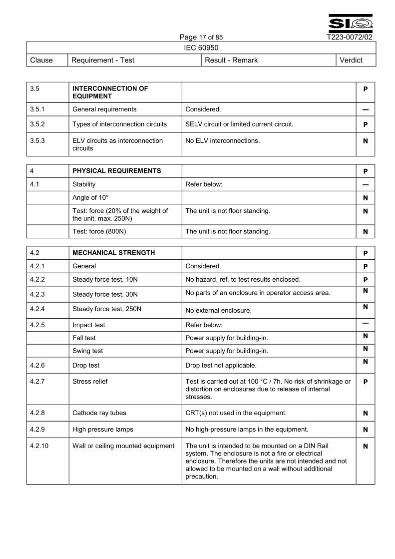
3.5 INTERCONNECTION OF
EQUIPMENT P
3.5.1 General requirements Considered. �
3.5.2 Types of interconnection circuits SELV circuit or limited current circuit. P
3.5.3 ELV circuits as interconnection circuits
No ELV interconnections. N
4 PHYSICAL REQUIREMENTS P
4.1 Stability Refer below: �
Angle of 10° N
Test: force (20% of the weight of the unit, max. 250N)
The unit is not floor standing. N
Test: force (800N) The unit is not floor standing. N 4.2 MECHANICAL STRENGTH P
4.2.1 General Considered. P
4.2.2 Steady force test, 10N No hazard, ref. to test results enclosed. P
4.2.3 Steady force test, 30N No parts of an enclosure in operator access area. N
4.2.4 Steady force test, 250N No external enclosure. N
4.2.5 Impact test Refer below: �
Fall test Power supply for building-in. N
Swing test Power supply for building-in. N
4.2.6 Drop test Drop test not applicable. N
4.2.7 Stress relief Test is carried out at 100 °C / 7h. No risk of shrinkage or distortion on enclosures due to release of internal stresses.
P
4.2.8 Cathode ray tubes CRT(s) not used in the equipment. N
4.2.9 High pressure lamps No high-pressure lamps in the equipment. N
4.2.10 Wall or ceiling mounted equipment The unit is intended to be mounted on a DIN Rail system. The enclosure is not a fire or electrical enclosure. Therefore the units are not intended and not allowed to be mounted on a wall without additional precaution.
N
Page 18 of 85 T223-0072/02
IEC 60950 Clause Requirement - Test Result - Remark Verdict
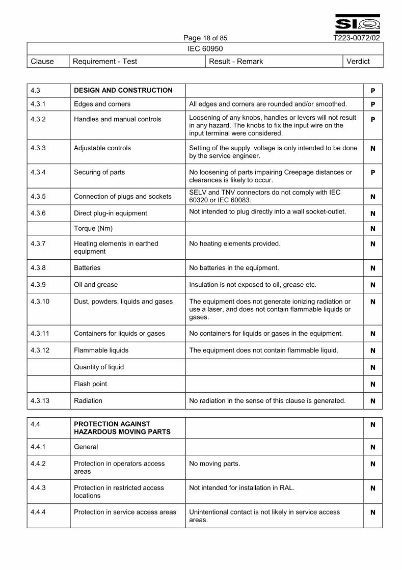
4.3 DESIGN AND CONSTRUCTION P
4.3.1 Edges and corners All edges and corners are rounded and/or smoothed. P
4.3.2 Handles and manual controls Loosening of any knobs, handles or levers will not result in any hazard. The knobs to fix the input wire on the input terminal were considered.
P
4.3.3 Adjustable controls Setting of the supply voltage is only intended to be done by the service engineer.
N
4.3.4 Securing of parts No loosening of parts impairing Creepage distances or clearances is likely to occur.
P
4.3.5 Connection of plugs and sockets SELV and TNV connectors do not comply with IEC 60320 or IEC 60083. N
4.3.6 Direct plug-in equipment Not intended to plug directly into a wall socket-outlet. N
Torque (Nm) N
4.3.7 Heating elements in earthed equipment
No heating elements provided. N
4.3.8 Batteries No batteries in the equipment. N
4.3.9 Oil and grease Insulation is not exposed to oil, grease etc. N
4.3.10 Dust, powders, liquids and gases The equipment does not generate ionizing radiation or use a laser, and does not contain flammable liquids or gases.
N
4.3.11 Containers for liquids or gases No containers for liquids or gases in the equipment. N
4.3.12 Flammable liquids The equipment does not contain flammable liquid. N
Quantity of liquid N
Flash point N
4.3.13 Radiation No radiation in the sense of this clause is generated. N
4.4 PROTECTION AGAINST
HAZARDOUS MOVING PARTS N
4.4.1 General N
4.4.2 Protection in operators access areas
No moving parts. N
4.4.3 Protection in restricted access locations
Not intended for installation in RAL. N
4.4.4 Protection in service access areas Unintentional contact is not likely in service access areas.
N
Page 19 of 85 T223-0072/02
IEC 60950 Clause Requirement - Test Result - Remark Verdict
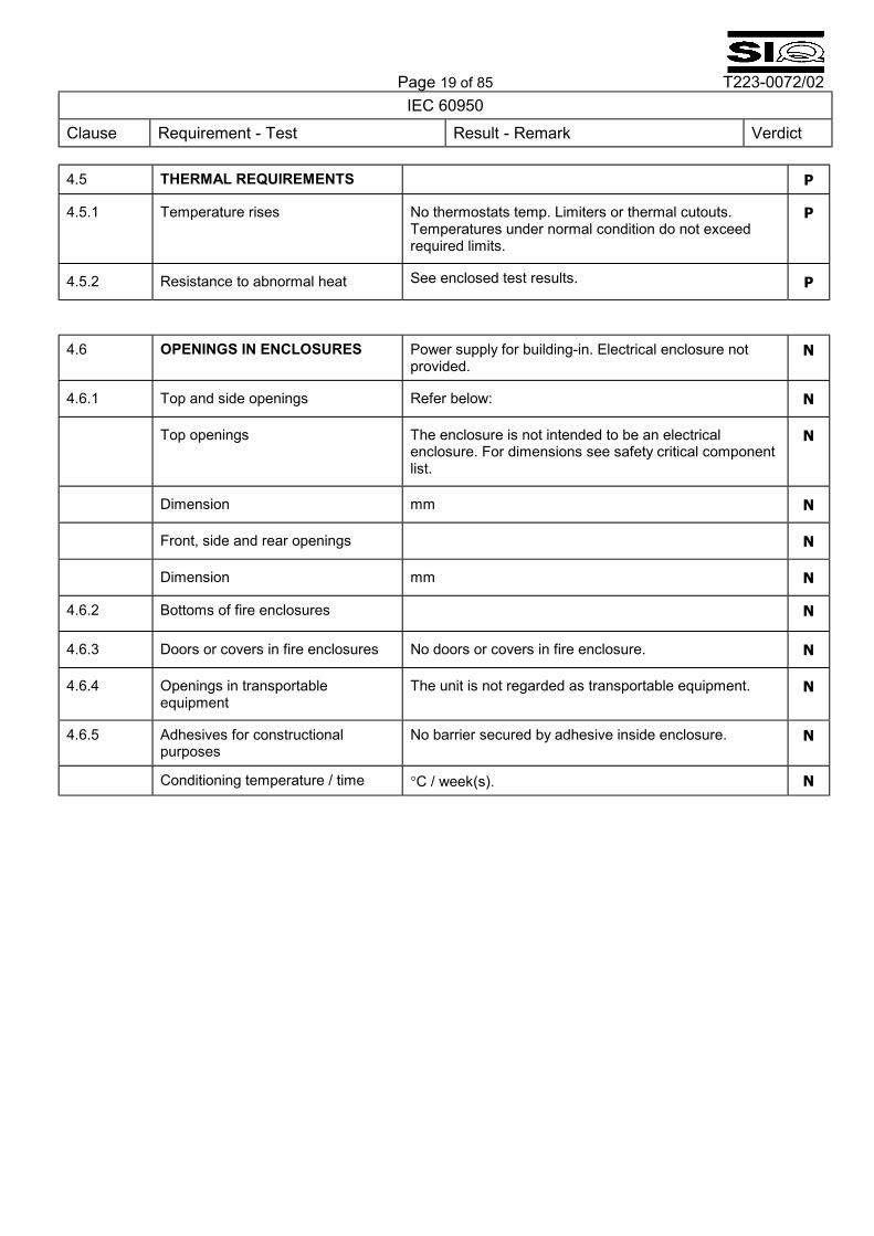
4.5 THERMAL REQUIREMENTS P
4.5.1 Temperature rises No thermostats temp. Limiters or thermal cutouts. Temperatures under normal condition do not exceed required limits.
P
4.5.2 Resistance to abnormal heat See enclosed test results. P
4.6 OPENINGS IN ENCLOSURES Power supply for building-in. Electrical enclosure not
provided. N
4.6.1 Top and side openings Refer below: N
Top openings The enclosure is not intended to be an electrical enclosure. For dimensions see safety critical component list.
N
Dimension mm N
Front, side and rear openings N
Dimension mm N
4.6.2 Bottoms of fire enclosures N
4.6.3 Doors or covers in fire enclosures No doors or covers in fire enclosure. N
4.6.4 Openings in transportable equipment
The unit is not regarded as transportable equipment. N
4.6.5 Adhesives for constructional purposes
No barrier secured by adhesive inside enclosure. N
Conditioning temperature / time °C / week(s). N
Page 20 of 85 T223-0072/02
IEC 60950 Clause Requirement - Test Result - Remark Verdict
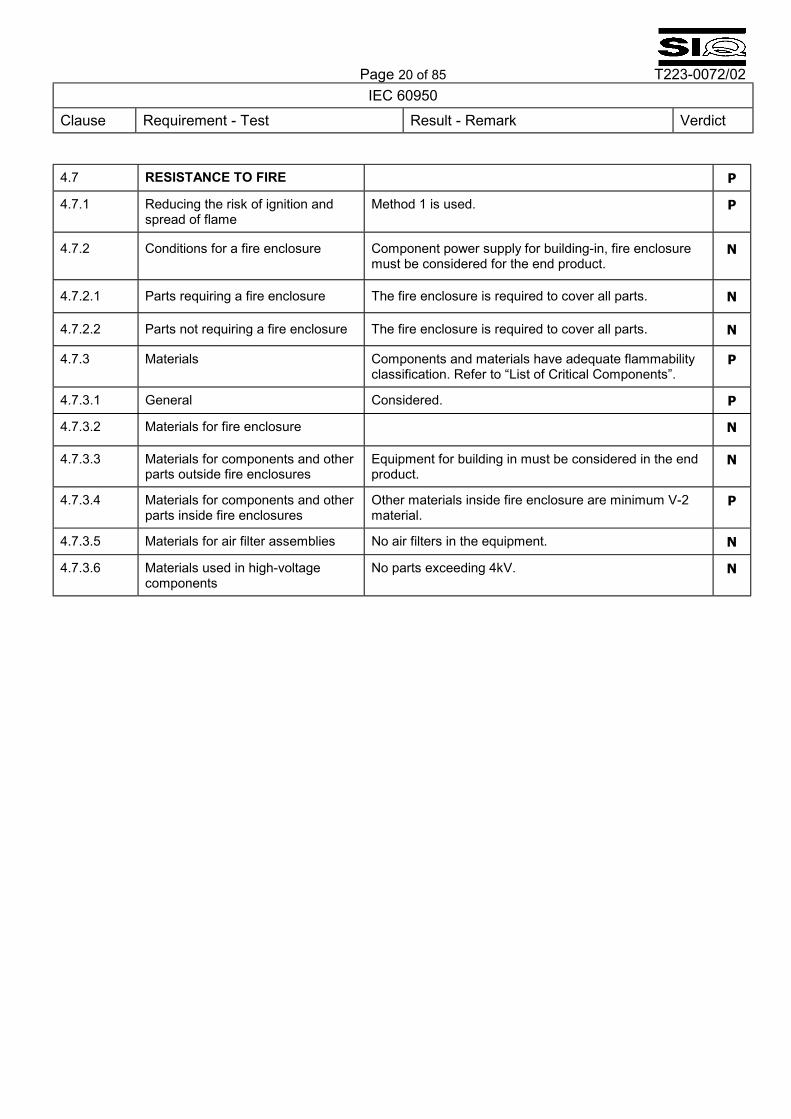
4.7 RESISTANCE TO FIRE P
4.7.1 Reducing the risk of ignition and spread of flame
Method 1 is used. P
4.7.2 Conditions for a fire enclosure Component power supply for building-in, fire enclosure must be considered for the end product.
N
4.7.2.1 Parts requiring a fire enclosure The fire enclosure is required to cover all parts. N
4.7.2.2 Parts not requiring a fire enclosure The fire enclosure is required to cover all parts. N
4.7.3 Materials Components and materials have adequate flammability classification. Refer to �List of Critical Components�.
P
4.7.3.1 General Considered. P
4.7.3.2 Materials for fire enclosure N
4.7.3.3 Materials for components and other parts outside fire enclosures
Equipment for building in must be considered in the end product.
N
4.7.3.4 Materials for components and other parts inside fire enclosures
Other materials inside fire enclosure are minimum V-2 material.
P
4.7.3.5 Materials for air filter assemblies No air filters in the equipment. N
4.7.3.6 Materials used in high-voltage components
No parts exceeding 4kV. N
Page 21 of 85 T223-0072/02
IEC 60950 Clause Requirement - Test Result - Remark Verdict
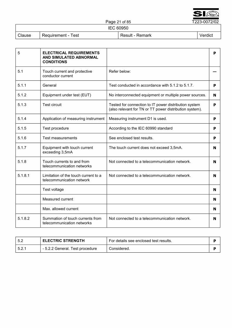
5 ELECTRICAL REQUIREMENTS AND SIMULATED ABNORMAL CONDITIONS
P
5.1 Touch current and protective conductor current
Refer below: �
5.1.1 General Test conducted in accordance with 5.1.2 to 5.1.7. P
5.1.2 Equipment under test (EUT) No interconnected equipment or multiple power sources. N
5.1.3 Test circuit Tested for connection to IT power distribution system (also relevant for TN or TT power distribution system).
P
5.1.4 Application of measuring instrument Measuring instrument D1 is used. P
5.1.5 Test procedure According to the IEC 60990 standard P
5.1.6 Test measurements See enclosed test results. P
5.1.7 Equipment with touch current exceeding 3,5mA
The touch current does not exceed 3,5mA. N
5.1.8 Touch currents to and from telecommunication networks
Not connected to a telecommunication network. N
5.1.8.1 Limitation of the touch current to a telecommunication network
Not connected to a telecommunication network. N
Test voltage N
Measured current N
Max. allowed current N
5.1.8.2 Summation of touch currents from telecommunication networks
Not connected to a telecommunication network. N
5.2 ELECTRIC STRENGTH For details see enclosed test results. P
5.2.1 - 5.2.2 General. Test procedure Considered. P
Page 22 of 85 T223-0072/02
IEC 60950 Clause Requirement - Test Result - Remark Verdict
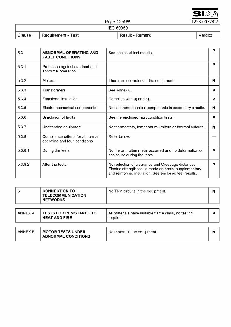
5.3 ABNORMAL OPERATING AND FAULT CONDITIONS
See enclosed test results. P
5.3.1 Protection against overload and abnormal operation
P
5.3.2 Motors There are no motors in the equipment. N
5.3.3 Transformers See Annex C. P
5.3.4 Functional insulation Complies with a) and c). P
5.3.5 Electromechanical components No electromechanical components in secondary circuits. N
5.3.6 Simulation of faults See the enclosed fault condition tests. P
5.3.7 Unattended equipment No thermostats, temperature limiters or thermal cutouts. N
5.3.8 Compliance criteria for abnormal operating and fault conditions
Refer below: �
5.3.8.1 During the tests No fire or molten metal occurred and no deformation of enclosure during the tests.
P
5.3.8.2 After the tests No reduction of clearance and Creepage distances. Electric strength test is made on basic, supplementary and reinforced insulation. See enclosed test results.
P
6 CONNECTION TO
TELECOMMUNICATION NETWORKS
No TNV circuits in the equipment. N
ANNEX A TESTS FOR RESISTANCE TO HEAT AND FIRE
All materials have suitable flame class, no testing required.
P
ANNEX B MOTOR TESTS UNDER ABNORMAL CONDITIONS
No motors in the equipment. N
This is an extract of the CB-Scheme report with the most important information. If a complete copy of the report is required, please contact your PULS sales representative.